Communication

Forming Rate Dependence of Novel Austenitising Bending Process for a High-Strength Quenched Micro-Alloyed Steel: Experiments and Simulation

1
School of Mechanical, Materials, Mechatronics and Biomedical Engineering, University of Wollongong, Wollongong, NSW 2522, Australia
2
Welding and Additive Manufacturing Centre, Cranfield University, Cranfield MK43 0AL, UK
3
College of Mechanical and Electrical Engineering, Central South University, Changsha 410083, China
4
School of Materials Science and Engineering, University of Science and Technology Beijing, Beijing 100083, China
*
Author to whom correspondence should be addressed.
Processes 2025, 13(2), 441; https://doi.org/10.3390/pr13020441
Submission received: 7 August 2023 / Revised: 20 September 2023 / Accepted: 5 February 2025 / Published: 6 February 2025
(This article belongs to the Special Issue Processing, Manufacturing and Properties of Metal and Alloys)

Abstract

:
This austenitising bending investigation was carried out in a vacuum environment with the forming rates of 1, 10, and 100 mm/min under a certain bending temperature of 900 °C by a thermomechanical simulator. The enhanced strength at the accelerated forming rate and on the compression/tension zones throughout the thickness of the bent plates was discussed in detail in terms of dislocation pile-up, smaller prior austenite grain size, dynamic recrystallisation, smaller martensite packet, and stress-neutral layer. Since the simulation results were validated to match the experimental trend, this investigation could be applied as a valuable reference to simulate the practical manufacturing process of railway fasteners.

1. Introduction

Room-temperature bending has been reported to be easily carried out on some metallic materials [1,2,3,4,5]. Nevertheless, there were few studies regarding hot bending investigation, especially under a complete austenitising state due to the limits of experimental conditions. Si–Cr micro-alloyed steel as new-generation steel applied in railway spring clips has been widely concerned due to its excellent performance resulting from dual-phase structure (bainite ferrite and retained austenite) [6,7]. To further match the faster train speed (up to 350 km/h), the generational update of rail clips becomes essential to ensure the railway operates more safely [8].
The preference for conducting bending experiments at room temperature is primarily due to their ease of implementation. Room-temperature bending studies have gained significant traction, with a focus on materials like high-strength steel [9], DP 590/780 steel [2,10], pipeline steel [1], and dual-phase steel [3,11]. In practical production, it may not suggest rail clips be fabricated at low temperatures because the bainite transformation would be greatly restrained [12], while high-temperature forming brings more advantages, such as better formability, decreasing force, and less spring-back [13]. Surprisingly, there has been limited attention given to high-temperature bending processes, particularly when the bending temperature exceeds the complete austenitising state. From the application perspective, limited investigation on the influence of the practical forming process of spring clips can be found due to complex bending angles.
To forward the intention of suiting for actual production, a custom-built die was designed to simulate various bending conditions. Since the bending rate affects the efficiency, cost, and performance of rail clips more directly, this investigation will comprehensively discuss the relationship between the forming rate and mechanical properties. The strength mechanism related to room-temperature and high-temperature microstructures particularly correlates to the practical conditions, which will be valuable references for the rail clip manufacturing process.

2. Materials and Methods

Testing plates were extracted from a rotary-forging Si–Cr steel rod (0.55C-1.4Si-0.65Mn-0.65Cr-0.11Ni-0.12Cu-0.012S-0.018P-Balanced Fe, in wt%) with the dimension of 60 × 10 × 2 mm. The forming process was carried out using a custom-built die in the vacuum environment on the Gleeble-3500 thermomechanical simulator (Dynamic Systems Inc., Poestenkill, NY, USA). Before the bending operation, all the plates were heated to 900 °C with a heating rate of 10 °C/s and then held for 1.5 min to keep a homogenised temperature during bending. The selection of testing temperature referred to our previously calculated phase diagram, which indicates that the austenitising transformation temperature is below 800 °C [7]. Three different bending rates (1, 10, and 100 mm/min) were selected until the bending distance reached 15 mm, which corresponded to the bending time of 900, 90, and 9s, respectively. To realise precise temperature control during the bending progress, the Gleeble system is equipped with sophisticated temperature control mechanisms. It uses various heating elements, such as resistance heating or induction heating, to raise the temperature of the sample. The heating elements are designed to provide precise and uniform heating across the sample. Moreover, thermocouples are temperature sensors that are in contact with the samples to continuously measure the temperature in real time. This information is sent to a controller, which adjusts the heating elements accordingly to maintain the desired temperature. Thereafter, water quenching was applied to keep the high-temperature microstructures. The electron Backscattered Diffraction (EBSD) technique was applied in a mapping area of 200 × 90 μm to observe microstructures with the 0.18 μm step size by JEOL JSM-7001F microscope (JEOL Ltd., Tokyo, Japan). The austenite reconstruction was carried out by the MTEX toolbox, enabling further crystal analysis [14].

3. Results and Discussion

Figure 1a exhibits the sample assembled by the mould and the simplified model in the simulation. To compare and validate the entire bending process, the finite element (FE) modelling was carried out in the current study, as well. In the FE modelling, the mechanical property of the experimental steel refers to our previous study [12,15,16]. This study determined the yield and tensile stresses to be 84.2 MPa and 138.6 MPa, respectively. The Young’s modulus was fixed at 210 GPa. Additionally, a Poisson’s ratio of 0.33 was chosen for this investigation. In the modelling phase, both the holder and clamp were characterised as discrete rigid bodies using the R3D4 element type. Conversely, the blank was represented as a deformable solid model with the C3D8R element type. Considering the lubrication conditions, a friction coefficient of 0.1 was applied to all contact areas. Initially, there were no constraints on the blank, while the holder and clamp were fully constrained in all directions. The punch was defined with a single degree of freedom along the bending direction. The mesh size for the blank model was set to 0.5 mm, and all other rigid bodies were defined with a size of 1.5 mm. The equivalent stress contour distribution displayed in Figure 1b indicates the stress magnitude had a decreasing gradient from surfaces to the central areas throughout the sample thickness in forming rates, while the maximum stress value increased with the decrease in bending time. Furthermore, the bending rate presented a slight influence on the stress concentration region. Simultaneously, the stress neutral layer (SNL) of each bent specimen obtained from transverse stress (S22) distribution also exhibited little deviation based on the ratio of SNL to plate thickness (see Figure 1c).
Since the loading force during the forming process is normally considered to be an important reference in practical production [17], its evolution under different bending rates was investigated and is illustrated in Figure 1d. The good agreement between the modelling and experiments indicates the dependability of this investigation. Apparently, the value of the loading force showed a downward trend with the decrease in bending rate. The higher bending rate would bring about a greater loading force because of the inadequate effects of dynamic recovery (DRV) and dynamic recrystallisation (DRX). At the early bending stage, work hardening (WH) was enhanced due to dominant dislocation, increasing loading force. Owing to the neutralisation of dynamic softening and WH, the force under all bending conditions displayed a softening trend after the peak point, indicating that the DRX became dominant at the later bending stage. Furthermore, according to the obtained micro-hardness results (Figure 1e), the mean hardness value increased with the increase in bending rate resulting from the comprehensive factors of DRV and DRX, exhibiting a similar developing trend to loading forces. Here, the obvious hardness gradient could be observed from each bent plate, as well. The smaller value could be obtained in the central area, which might be ascribed to the SNL mentioned above. Apart from that, the accumulated dislocation on the compression and tension zones would be another factor that was responsible for the increased hardness. In addition, the relatively smaller hardness value could be detected on the edges throughout the thickness of each specimen, and it becomes more pronounced as bending time goes on. This is because the water quenching was followed by vacuum unloading after the bending process. In the quenching process, oxidation and decarburisation would significantly influence the strength of materials [18].
Grain boundary (GB) maps at the mid and bot regions of the bent specimens are exhibited in Figure 2a,c,e,g,i,k. To reflect the GB, the misorientation angles between 20° and 45° were plotted in red, while the counterparts over 45° were labelled by cyan. In this manuscript, mid refers to the middle region, and bot refers to the surface region of the testing plate. Since the prior austenite (PA) GBs are proposed to have random misorientation boundaries [19], this division of misorientation angles was a discovery only suitable for this material. From the GB maps, it is notable that the grain orientation shows no correlation with the bending process. Moreover, the red lines are selected to indicate the DRX grain distribution. The cyan regions could be applied to suggest the non-recrystallised austenite and grown/compressed austenite matrix. Based on that, only partial DRX could be achieved in each bending sample. In addition, Kernel average misorientation (KAM) analysis and corresponding calculated geometrically necessary dislocations (GND) displayed in Figure 2b,d,f,h,j,l) clarifies that more DRV could be detected in the bot region in comparison to the value obtained from the central area regardless of the bending rate. The overall GND density value decreased as the bending rate accelerated, further clarifying the smaller hardness and loading force under this condition.
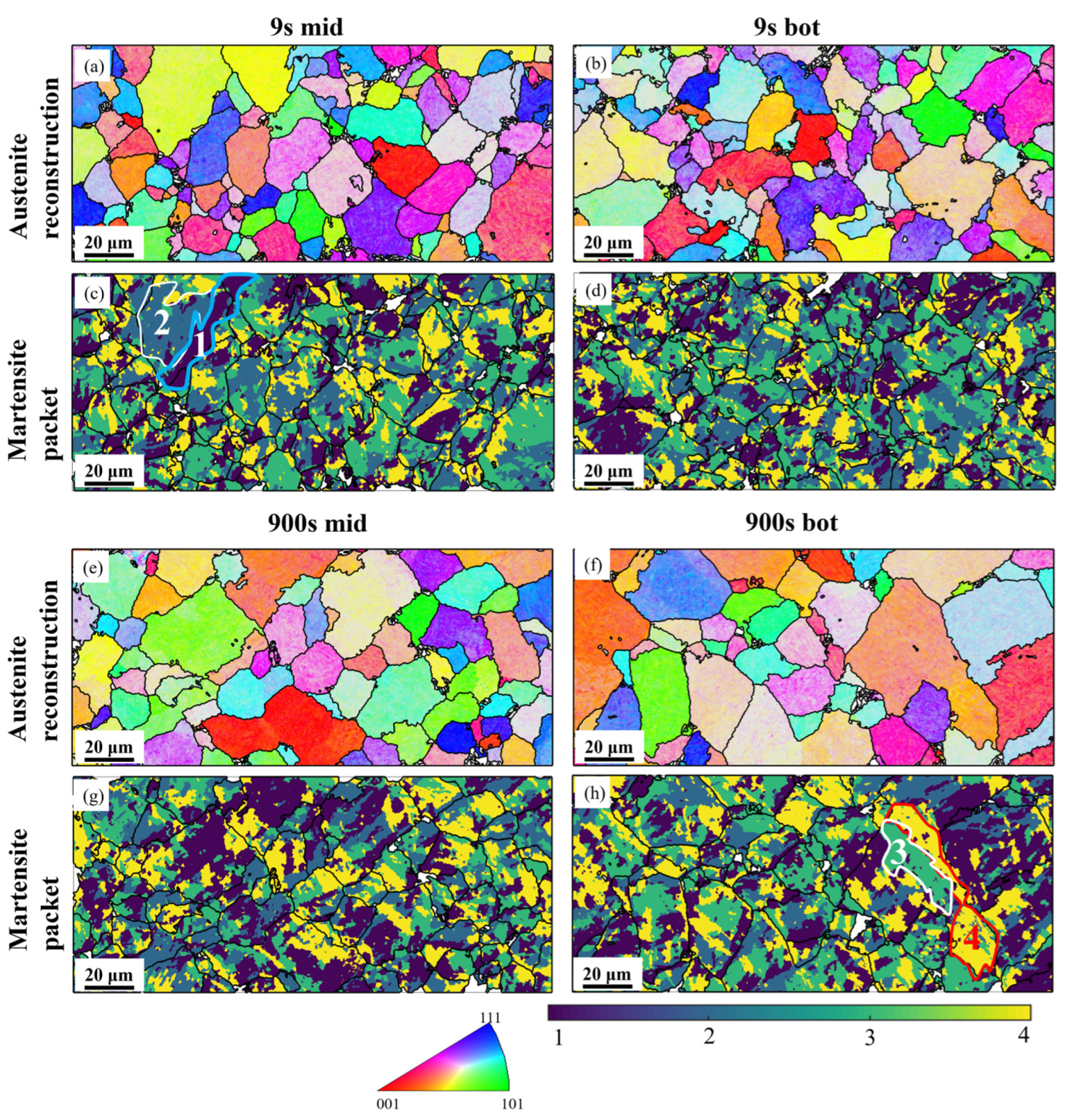
The crystallographic toolbox MTEX was used to reconstruct PA grains to illustrate the strength mechanism in correlation with the forming rate from another aspect. Note that the predicted PA grain coarsened at a low bending rate in comparison to that at a high bending rate (see Figure 3a,b,e,f). This is because the larger forming rate allows more PA grain nucleation sites to become active, resulting in a smaller PA grain size. Although the larger PA with a lower incidence of PA grain boundaries has higher hardenability, which would lead to a larger volume fraction of martensite in the final product phases and, thereby, a larger hardness value [20], the forming rate as the dominating factor greatly influenced the plate strength than PA grain size based on the obtained hardness value shown in Figure 1e. In addition, it is worth mentioning the significant influence of the martensite packet on the mechanical property. Based on the predicted results displayed in Figure 3c,d,g,h, an interesting finding is that the size of the martensite packet (circled in Figure 3c,h) is closely related to the PA size. The relatively larger PA at a lower bending rate would contain martensite packets with a larger packet size, which decreases the strength of steels [21]. The significant effect of martensite block and packet dimensions on both strength and toughness has been substantiated in various metallic materials, including low-carbon steels and Fe–C alloys [7]. Therefore, it is crucial to explore how the crystallographic and morphological attributes of martensite change in the experimental steel. This exploration is vital for understanding the variation in hardness at different bending temperatures. Studies [6,7] have demonstrated that both the martensite variant size and the size of the packet containing the variant exert a more pronounced influence on the mechanical properties of the material. Specifically, reducing the packet size has been found to enhance the strength of steels with a lath martensite (LM) structure. Consequently, alongside the previously mentioned factors such as SNL, DRV associated with dislocations, grain size in PA, and DRX, another dominant factor affecting strength is the size of the martensite packets.
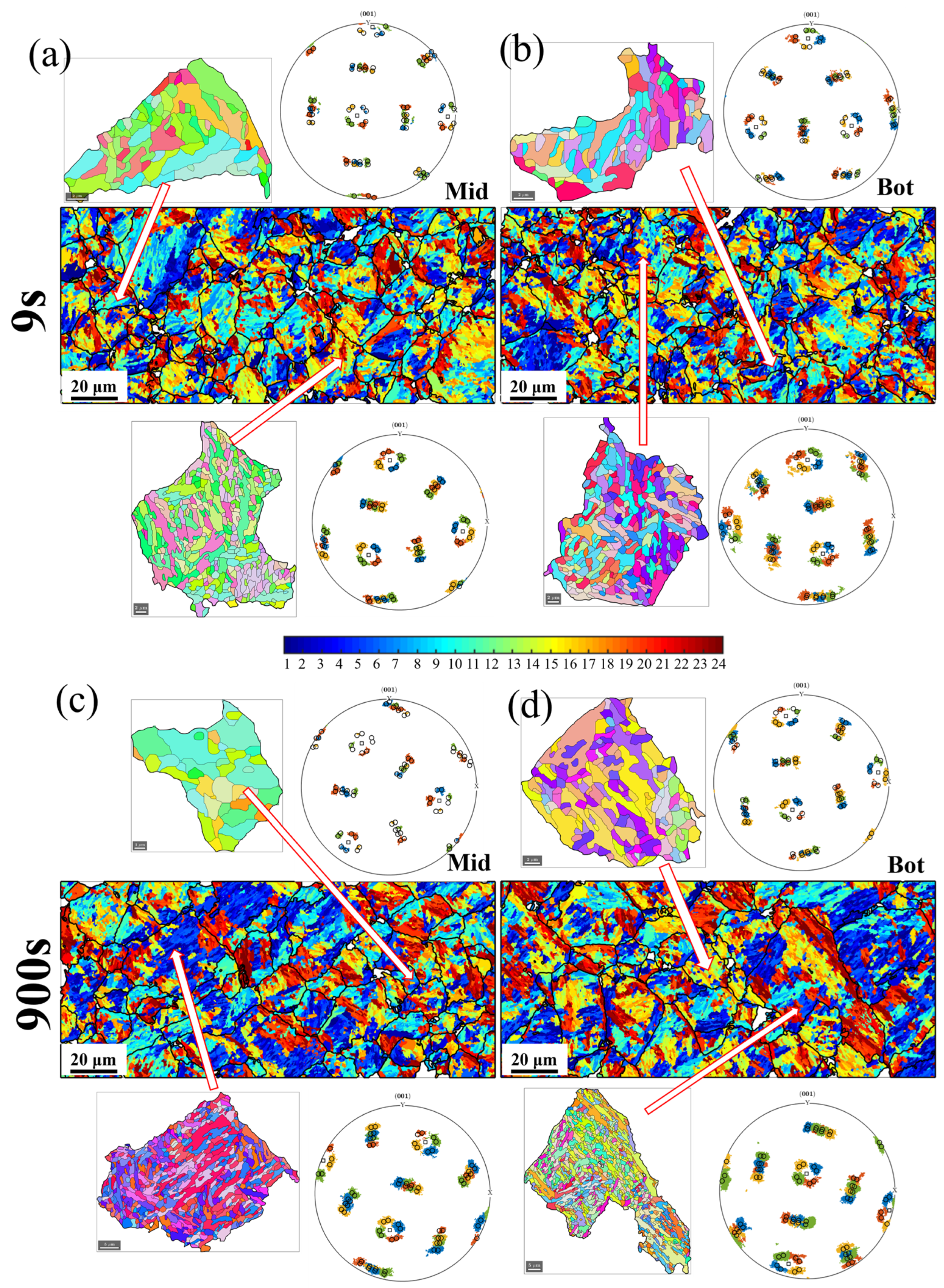
In addition, martensite structures are normally followed by the K–S rules, which have 24 variants and transform from a single PA [17]. In this study, the prediction of martensite variants under various bending conditions is exhibited in Figure 4a–d. Notably, the absent variants could be detected in a smaller PA grain, while the larger PA grain would have the capacity to allow for more nucleation of martensite variants. Typically, the absence of the variant was attributed to a natural occurrence resulting from limited transformation space, which is influenced by the size of the PA grains. Therefore, it can be speculated that variants are dependent on the PA grain no matter what kind of forming condition.

4. Conclusions

The forming rate, as the important indicator of spring clip in practical production, greatly influences the microstructure and mechanical performance. In this study, the work hardening degree was enhanced with the increase in bending rate due to the following reasons: more dislocation pile-ups; more DRX; and smaller martensite packet size. The hardness gradient was mainly caused by the accumulated dislocation on the compression/tension zones. The stress-neutral layer near the central area throughout the plate thickness was also responsible for the smaller hardness. The consistent results obtained from the experiments and simulation well simulated the practical manufacturing process for the spring clip, which will be a useful reference in the rail track of the railway system.

Author Contributions

Conceptualization, Y.L. and J.H.; methodology, J.W.; software, Z.L.; validation, D.P.; formal analysis, F.J.; investigation, F.L.; resources, Z.J.; data curation, Y.L.; writing—original draft preparation, Y.L.; writing—review and editing, Y.L. and Z.J.; supervision, Z.J.; project administration, Z.J. All authors have read and agreed to the published version of the manuscript.

Funding

This investigation was financially supported by the Australian Research Council (ARC) ITTC-Rail Centre.

Data Availability Statement

All data included in the current work are available upon request by contacting the corresponding author.

Acknowledgments

The authors appreciate Azdiar A. Gazder’s support in the austenite reconstruction.

Conflicts of Interest

The authors declare no conflict of interest.

References

  1. Mandal, A.; Syed, B.; Bhandari, K.K.; Bhattacharya, B.; Deb, A.; Singh, S.B.; Chakrabarti, D. Cold-bending of linepipe steel plate to pipe, detrimental or beneficial? Mater. Sci. Eng. A 2019, 746, 58–72. [Google Scholar] [CrossRef]
  2. Chung, K.-H.; Lee, W.; Kim, J.H.; Kim, C.; Park, S.H.; Kwon, D.; Chung, K. Characterization of mechanical properties by indentation tests and FE analysis—Validatiosn by application to a weld zone of DP590 steel. Int. J. Solids Struct. 2009, 46, 344–363. [Google Scholar] [CrossRef]
  3. Poulin, C.M.; Korkolis, Y.P.; Kinsey, B.L.; Knezevic, M. Over five-times improved elongation-to-fracture of dual-phase 1180 steel by continuous-bending-under-tension. Mater. Des. 2019, 161, 95–105. [Google Scholar] [CrossRef]
  4. Li, H.; Venezuela, J.; Zhou, Q.; Luzin, V.; Yan, M.; Shi, Z.; Knibbe, R.; Zhang, M.; Dong, F.; Dargusch, M.S.; et al. Hydrogen-induced delayed fracture of a 1180 MPa martensitic advanced high-strength steel under U-bend loading. Mater. Today Commun. 2021, 26, 101887. [Google Scholar] [CrossRef]
  5. Iftimiciuc, M.; Lache, S.; Vandepitte, D.; Velea, M.N. Bending performance of a sandwich beam with sheet metal pyramidal core. Mater. Today Commun. 2022, 31, 103490. [Google Scholar] [CrossRef]
  6. Lu, Y.; Xie, H.; Wang, J.; Jia, F.; Lin, F.; Zhou, C.; Xu, J.; Han, J.; Jiang, Z. Ex situ analysis of high-strength quenched and micro-alloyed steel during austenitising bending process: Numerical simulation and experimental investigation. Int. J. Adv. Manuf. Technol. 2022, 120, 8293–8309. [Google Scholar] [CrossRef]
  7. Lu, Y.; Xie, H.; Wang, J.; Jia, F.; Li, Z.; Kamali, H.; Xu, J.; Han, J.; Jiang, Z. Design of a novel austenitising bending process in forming characteristics of high-strength quenched and micro-alloyed steel: Experiment and simulation. Mater. Des. 2022, 215, 110458. [Google Scholar] [CrossRef]
  8. Yuan, Z.; Zhu, S.; Yuan, X.; Zhai, W. Vibration-based damage detection of rail fastener clip using convolutional neural network: Experiment and simulation. Eng. Fail. Anal. 2021, 119, 104906. [Google Scholar] [CrossRef]
  9. Khan, S.H.; Ahmed, M.S.; Ali, F.; Nusair, A.; Iqbal, M.A. Investigation of high strength steel bending. Eng. Fail. Anal. 2009, 16, 128–135. [Google Scholar] [CrossRef]
  10. Barrett, T.J.; Knezevic, M. Modeling material behavior during continuous bending under tension for inferring the post-necking strain hardening response of ductile sheet metals: Application to DP 780 steel. Int. J. Mech. Sci. 2020, 174, 105508. [Google Scholar] [CrossRef]
  11. Liu, Y.; Fan, D.; Bhat, S.P.; Srivastava, A. Ductile fracture of dual-phase steel sheets under bending. Int. J. Plast. 2020, 125, 80–96. [Google Scholar] [CrossRef]
  12. Lu, Y.; Xie, H.; Wang, J.; Li, Z.; Jia, F.; Wu, H.; Han, J.; Jiang, Z. Influence of hot compressive parameters on flow behaviour and microstructure evolution in a commercial medium carbon micro-alloyed spring steel. J. Manuf. Process. 2020, 58, 1171–1181. [Google Scholar] [CrossRef]
  13. Simonetto, E.; Ghiotti, A.; Bruschi, S. High accuracy direct hot bending of hollow profiles. Manuf. Lett. 2021, 27, 63–66. [Google Scholar] [CrossRef]
  14. Niessen, F.; Nyyssönen, T.; Gazder, A.A.; Hielscher, R. Parent grain reconstruction from partially or fully transformed microstructures in MTEX. J. Appl. Crystallogr. 2022, 55, 180–194. [Google Scholar] [CrossRef] [PubMed]
  15. Lu, Y.; Xie, H.; Wang, J.; Li, Z.; Lin, F.; Han, J.; Han, J.; Jiang, Z. Characteristic flow behaviour prediction and microstructure analysis of a commercial Si–Cr micro-alloyed spring steel under isothermal compression. Vacuum 2021, 186, 110066. [Google Scholar] [CrossRef]
  16. Lu, Y.; Xie, H.; Wang, J.; Jia, F.; Li, Z.; Lin, F.; Pan, D.; Han, J.; Jiang, Z. Simulation, microstructure and austenite reconstruction of a medium carbon micro-alloyed steel subjected to an austenitising bending process. Mater. Lett. 2021, 305, 130772. [Google Scholar] [CrossRef]
  17. Li, Z.; Zhao, J.; Jia, F.; Zhang, Q.; Liang, X.; Jiao, S.; Jiang, Z. Numerical and experimental investigation on the forming behaviour of stainless/carbon steel bimetal composite. Int. J. Adv. Manuf. Technol. 2019, 101, 1075–1083. [Google Scholar] [CrossRef]
  18. Zinkle, S.J.; Was, G.S. Materials challenges in nuclear energy. Acta Mater. 2013, 61, 735–758. [Google Scholar] [CrossRef]
  19. Lan, L.; Zhou, W.; Misra, R.D.K. Effect of hot deformation parameters on flow stress and microstructure in a low carbon microalloyed steel. Mater. Sci. Eng. A 2019, 756, 18–26. [Google Scholar] [CrossRef]
  20. Javaheri, V.; Kolli, S.; Grande, B.; Porter, D. Insight into the induction hardening behavior of a new 0.40% C microalloyed steel: Effects of initial microstructure and thermal cycles. Mater. Charact. 2019, 149, 165–183. [Google Scholar] [CrossRef]
  21. Kitahara, H.; Ueji, R.; Tsuji, N.; Minamino, Y. Crystallographic features of lath martensite in low-carbon steel. Acta Mater. 2006, 54, 1279–1288. [Google Scholar] [CrossRef]
Figure 1. (a) Diagrammatic drawing of the simplified model; (b) equivalent stress distribution; (c) transverse stress (S22) distribution; (d) the comparison of simulated loading force with experiments; and (e) hardness distribution under different bending conditions.
Processes 13 00441 g001
Figure 2. (a,c,e,g,i,k) GB maps under different bending rates in the mid and bot areas; (b,d,f,h,j,l) corresponding KAM maps and GND density distribution.
Processes 13 00441 g002
Figure 3. (a,b,e,f) Parent austenite grain reconstruction of different bent samples at mid and bot areas; (c,d,g,h) corresponding distribution of martensite packet.
Processes 13 00441 g003
Figure 4. Martensite variants of samples bent at 100 mm/min of (a) mid and (b) bot areas and 1 mm/min of (c) mid and (d) bot areas; the individual grain and corresponding pole figures are provided.
Processes 13 00441 g004
Disclaimer/Publisher’s Note: The statements, opinions and data contained in all publications are solely those of the individual author(s) and contributor(s) and not of MDPI and/or the editor(s). MDPI and/or the editor(s) disclaim responsibility for any injury to people or property resulting from any ideas, methods, instructions or products referred to in the content.