Abstract
In response to the issues of low energy recovery efficiency, single- and low-capacity energy storage methods, and insufficiently diverse control strategies in hydrostatic transmission systems, this paper analyzes hydrostatic systems from the perspectives of hydraulic principles and control strategies. Hydrostatic transmission systems are divided into three types: pump-controlled hydraulic systems, secondary regulation hydraulic systems, and adaptive regulation systems. The design concepts and working principles of hydraulic systems are discussed, and the control strategies for hydrostatic transmission systems are categorized into torque control, fuzzy control, and optimal control strategies. Operating conditions are analyzed, and the advantages and disadvantages of traditional control strategies are compared. The results show that utilizing techniques such as adaptive regulation to reduce the loss of energy in the transfer process and in the transformation of secondary components, as well as combining a variety of methods for integrated control, can effectively improve the efficiency of these systems. The development direction of hydrostatic transmission systems is also discussed, including further development into oil–hydraulic hybrid systems, utilization of artificial intelligence technology and network technology, optimized design concepts, and the intelligence of hydrostatic transmission systems.
1. Introduction
In recent years, the concept of green design has gradually gained importance with the decrease in natural fuel resources and the increase in environmental problems. Hydraulic systems play an important role in different applications such as heavy industrial equipment, earth-moving equipment, off-road vehicles, and new energy vehicles [1]. At present, regarding transmission devices that can basically meet the various tasks and functional requirements of the vehicle and traveling machinery transmission devices with an internal combustion engine as the power source, there are mainly four kinds of purely mechanical, hydraulic, electric, and hydraulic technologies and their fit forms. Purely mechanical transmission has the advantage of high efficiency in steady-state transmission and low manufacturing cost. It still occupies the dominant position in the fields of general passenger and freight cars with a relatively small speed regulation range, agricultural machinery with strict requirements on fuel economy, and agricultural tractors with constant working speed such as ploughing [2]. The four types of transmission are shown in Figure 1.
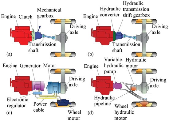
Figure 1.
Four types of transmission for traveling machines: (a) purely mechanical transmissions; (b) hydrodynamic drive; (c) electric transmissions; (d) hydraulic transmissions.
Purely mechanical transmission is simple in structure, intuitive in function, and suitable for low-speed and constant-speed mechanical transmission, but it is difficult to realize remote control and automatic control. The hydrodynamic drive is developed from purely mechanical transmission, and it can change the torque when the load changes [3,4], but the steady state efficiency is low. Electric transmission has good regulating performance, which can make the engine run stably under favorable working conditions. Moreover, in electric transmission, each unit can be adjusted independently or comprehensively, resulting in good adaptability to multi-power systems and multi-user systems, but it is limited by the component materials at present [5]. The layout of hydraulic transmission is flexible and convenient, and the components are connected by pipes, which is less constrained by mechanical structure. Moreover, hydraulic transmission has good universality and loose matching conditions with electronic control systems and various types of prime movers, so it is widely used in walking machinery [6,7]. Hydrostatic drive is one of the branches of hydraulic transmission technology. The characterization of the four drives is shown in Table 1.
The hydraulic transmission system of construction machinery can be divided into an open system and [8] a closed system according to the hydraulic circuit. An open circuit means that the hydraulic pump sucks oil from the tank, drives the actuator (e.g., hydraulic cylinder and hydraulic motor) through the hydraulic valve, and after that, the oil returns to the tank. The tank is connected to the atmosphere through an air filter, which is used to equalize the volume change of the fluid in the piping system and the actuator. Overall, the system is connected to the atmosphere and is open. Since the oil from the system work is returned to the oil tank, the oil tank can dissipate heat and precipitate impurities [9]. However, because the oil is often in contact with the air, the air can easily penetrate the system, resulting in the need to set up a backpressure valve on the road, which will cause additional energy loss, meaning that the temperature of the oil rises [10,11]. In a closed transmission system, the suction oil of the hydraulic pump is connected to the return oil of the actuator so that the oil out of the hydraulic pump goes directly to the actuator and the return oil of the actuator goes directly to the inlet of the hydraulic pump, and the oil is closed in the system [12]. The variable speed and direction change of the working mechanism is realized by adjusting the variable mechanism of the pump or motor, which avoids the hydraulic shock and energy loss that occurs during the direction change of the open system. Two hydraulic circuits are shown in Figure 2.

Figure 2.
Two types of hydraulic circuits: (a) open circuit and (b) closed loop.

Table 1.
Characterization of four types of transmissions [3,4,5,6,7,13,14,15,16,17,18,19,20].
Table 1.
Characterization of four types of transmissions [3,4,5,6,7,13,14,15,16,17,18,19,20].
| Transmission Method | Advantages | Disadvantages |
|---|---|---|
| Purely mechanical transmissions | Simpler and more mature structure; higher steady-state transmission efficiency | Complex transmission system; difficult to realize remote and automatic control |
| Hydrodynamic drive | Higher power density; adapts to frequent changes in operating conditions | Less versatile; lower steady-state efficiency |
| Electric transmissions | Flexible layout; good regulation performance | Limited by materials and operating temperatures |
| Hydraulic transmissions | Flexible and easy layout; good versatility | Complex structure of the main hydraulic components; not suitable for long-distance stable driving |
Walking machines have frequent start–stop and reciprocating motions during operation. Deceleration, shifting, and braking at high loads require a lot of energy and some of that energy is lost, meaning that it is not fully utilized. At the same time, the complex arrangement of components will affect the heat dissipation of the system, which will reduce the working efficiency and the use time of components. Therefore, a lightweight design with hydraulic power plays a crucial role in reducing the gross vehicle weight and ground contact pressure. At the same time, the use of hydrostatic power recovery technology to recover kinetic and potential energy during operation is also a trend of energy-saving hydraulics, but the utilization rate of energy recovery is still relatively low; the hydraulic system has a single energy storage method and low capacity; and the control strategy is not diversified enough to adapt to the new energy-saving hydraulic technology.
This paper reviews some of the research results of domestic and foreign scholars in recent years on hydrostatic transmission systems and control strategies, summarizes the advantages and shortcomings of their respective experiences, and then analyzes the direction of the development of hydrostatic transmission systems in walking machinery.
2. Hydrostatic Transmission System
At present, in the construction machinery market, most medium-sized and large loaders use hydro-mechanical transmission systems, but due to their low transmission efficiency, poor matching, and other issues, they only meet the basic working requirements of loaders but do not meet the working requirements of loaders under extreme working conditions [13,14,15,16]. Therefore, in order to solve the above problems, scholars at home and abroad put forward hydrostatic transmission technology, which greatly optimized the overall structure of loaders. At the same time, the application of hydrostatic technology improves the working efficiency of the transmission system, thus satisfying the stable operation of the loader under several extreme working conditions and improving the usability of the loader [17,18,19,20]. On this basis, domestic and foreign scholars have proposed several new hydraulic systems applied to hydrostatic transmission.
2.1. Hydrostatic Transmission Pump-Controlled Hydraulic System
In 1954, the British Agricultural Engineering Research Institute put forward the pump-controlled hydraulic system for the first time, and they also applied the hydrostatic transmission device to traditional agricultural tractors. This tractor is the first vehicle driven by hydrostatic transmission technology in the world. Its hydraulic system adopts a variable pump and two hydraulic motors. There is no drive axle in the traditional sense, but the power is directly transmitted from the engine to the driving wheels through the hydrostatic system. This flexible layout and performance improvement have greatly promoted the development of hydrostatic transmission system technology. At present, there is still a lot of large-scale machinery using valve-controlled hydraulic systems; these systems suffer from energy loss, complex structure, noise and vibration, and other shortcomings [21].
2.1.1. Single-Pump, Single-Motor Systems
Due to their relatively simple structure and low cost, a single-pump control asymmetric hydraulic cylinder is the research hotspot of pump control systems [22].
Vinay Partap Singh, Ajit Kumar Pandey, and Kabir Dasgupta [23] analyzed the steady-state performance of a hydrostatic drive system consisting of a closed-loop controlled variable pump and a variable motor, which provides a reference for future experiments in selecting the control parameters of the pumps for better drive efficiency.
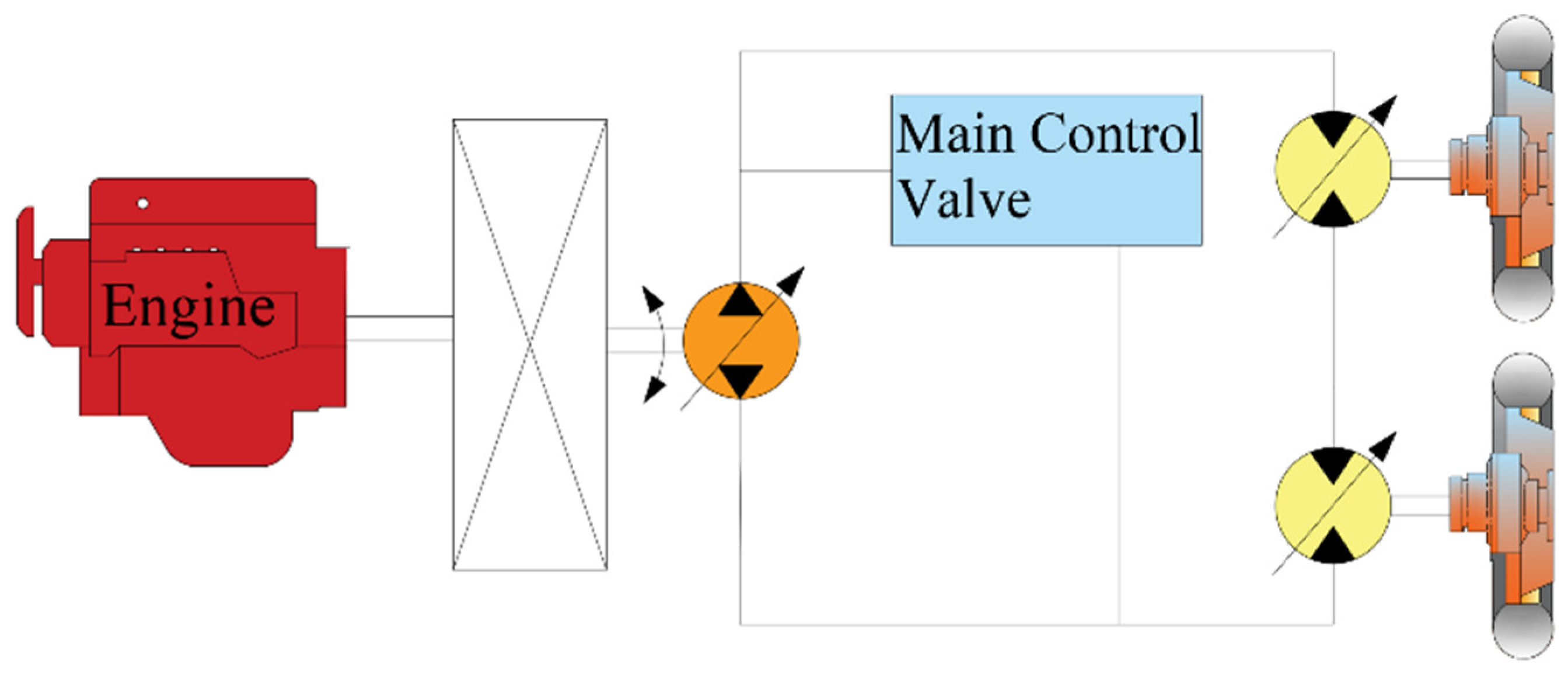
Wenwen Yang of Southwest Jiaotong University [24,25] made full use of the characteristics of hydrostatic transmission and adopted an electric motor as the power source of the system, which can improve the efficiency of the system and at the same time improve the load-bearing capacity of the hydrostatic system. Wenlong Huang of Henan University of Science and Technology [26] proposed a hydrostatic drive system for a grain combine harvester, which is composed of a single variable pump and a single variable motor, and the variable motor adopts a high-speed scheme, and the hydraulic motor in the low-speed scheme needs to bear the external radial and axial loads, and the cost is high. In the high-speed program, most of the external load is borne by the gearbox and the wheel side reducer, the hydraulic motor only needs to bear the radial load, the operation is more reliable, the service life is long, and its structure is shown in Figure 3. The system greatly alleviated the problem of system heating and increased the service life and reliability of the hydraulic system through a rational program, but the shortcoming is that the efficiency of the system cannot be maintained at the highest level.

Figure 3.
Hydrostatic drive system for a single-pump, single-motor grain combine harvester.
2.1.2. Single-Pump, Two-Motor Systems
Jinle Zhang, Feihong Mao, and Jing Guo [27] designed a hydrostatic drive system for a tracked vehicle using a dual variable pump and a dual variable motor, a structure characterized by the fact that both the pump and the motor can be independently controlled by electrohydraulic servo valves. The unilateral hydrostatic drive system for the tracked vehicle is shown in Figure 4. In the context of vehicle driving, the variable pump within the system is responsible for transforming mechanical energy from the engine into hydraulic energy, which is then utilized to propel the vehicle. When the vehicle decelerates or traverses an incline, the variable motor is pulled by the load, which transitions to pump mode, and energy is redirected back into the system. This energy can be recovered through an accumulator.
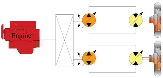
Figure 4.
Hydrostatic transmission system of the crawler truck.
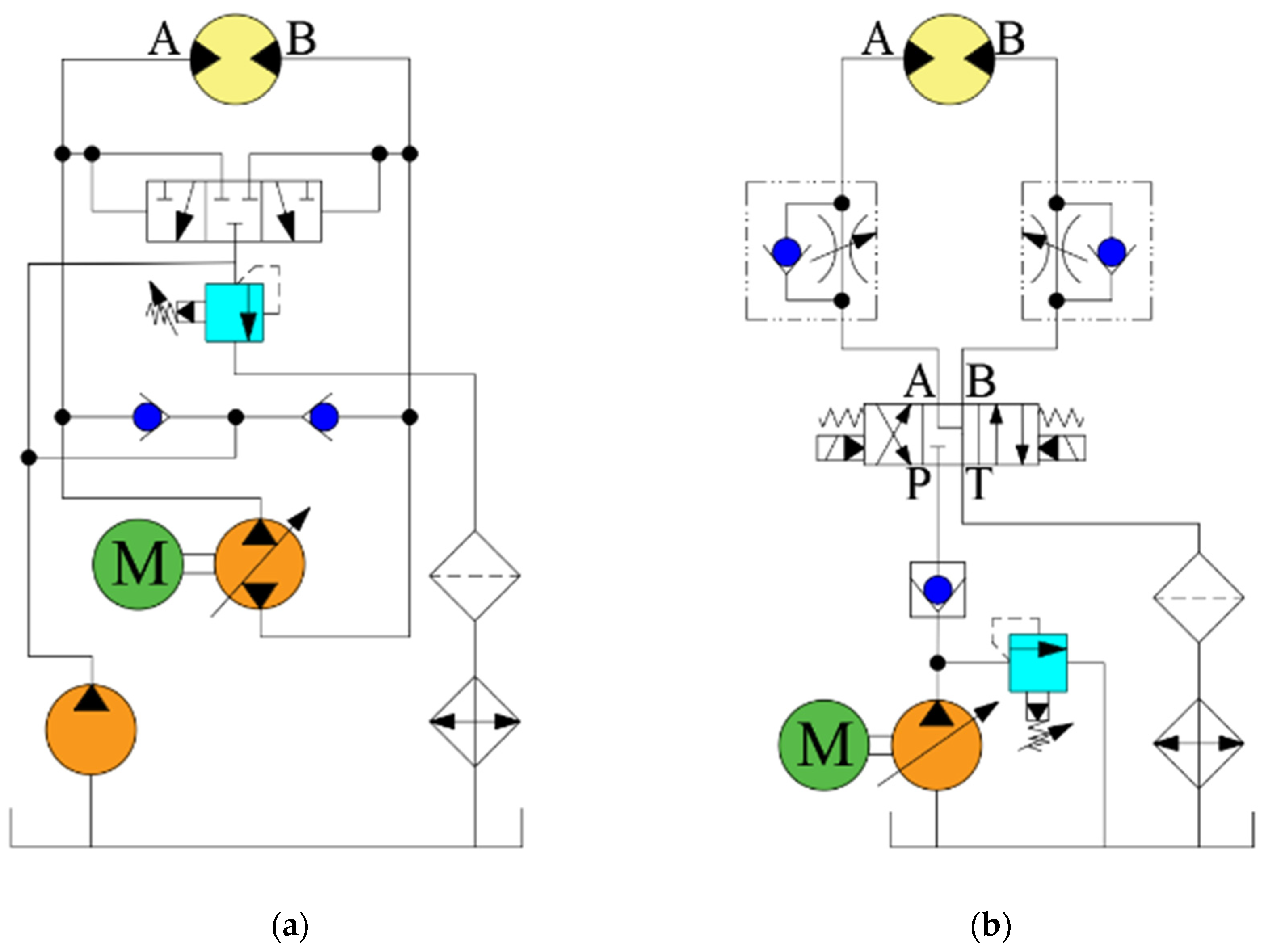
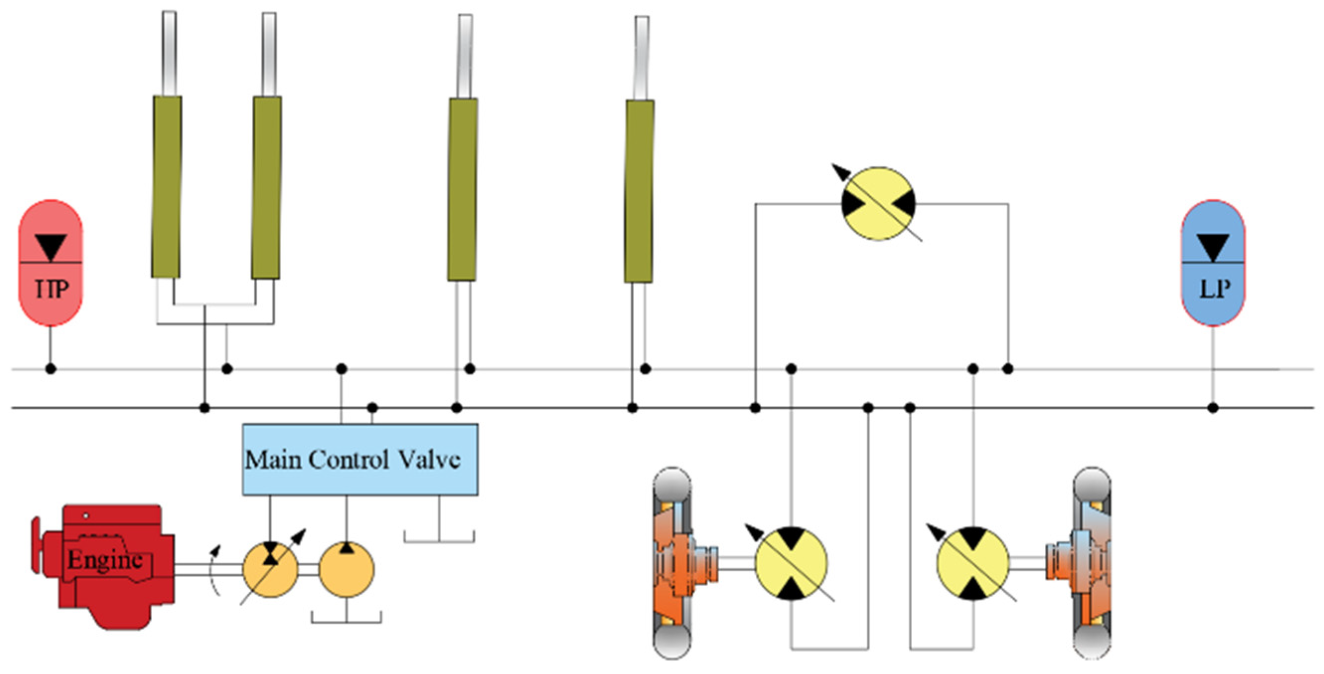
Songlin Wang [28] studied the hydrostatic transmission system of a loader with a single pump and double motors; the hydrostatic transmission system is shown in Figure 5. The system adopts two motors with different displacements. When the driving resistance is very large, the big motor and the small motor work at the same time to increase the displacement in order to provide traction; when the driving resistance is small, the loader needs a higher speed at this time, and the clutch between the output shaft of the large motor and the input shaft of the gearbox will be automatically disconnected so that the small motor can work alone at a lower displacement to provide higher speeds. Because both motors can operate at higher speeds and larger displacements throughout the process, the efficiency of the system can be maintained at a high level, thus making better use of the engine’s output power. It has been verified through tests that it can fully utilize the characteristics of the large motor with high torque and low RPM and the small motor with low torque and high RPM, and it also has a certain improvement effect on the service life of the components. The system takes into full consideration the optimal use of the actuator, which allows the engine to deliver optimal power in real time, but does not take into account the system energy recovery.

Figure 5.
Single-pump, double-motor traveling hydrostatic transmission system.
Shuzong Zhang [29] of Fujian University of Technology proposed a single and double-pump-controlled hybrid distributed excavator hydraulic system, which consists of a single-pump-controlled hydraulic system and a double-pump parallel pump-controlled hydraulic system, and its structure is shown in Figure 6. The single-pump-controlled hydraulic system is suitable for two-quadrant conditions, while the parallel pump-controlled system is suitable for four-quadrant conditions, and the combination of the two pump-controlled systems effectively realizes the flow compensation of the asymmetric hydraulic cylinders. Through the experimental study on the laboratory excavator, the parallel pump control system has good speed control performance with almost no speed fluctuation when the load force changes suddenly.

Figure 6.
Single–double pump control hybrid distributed excavator hydraulic system.
Pump-controlled hydraulic systems can be used to change the pump displacement or speed by using variable pumps, so that the pump outlet flow rate adapts to the needs of the load and adapts to a variety of complex working conditions, thus improving the efficiency of the system [30]. The combination of variable pumps and variable motors can make the construction vehicle maintain the most efficient driving efficiency in different speed ranges. With this solution, there are no redundant energy-consuming components between the energy source and the actuator, and both can be connected to the same energy storage element to recover energy. At the same time, the pump/motor can control the direction of the fluid by connecting it directly to the engine, thus reducing the use of directional control valves and achieving the effect of simplifying the structure of the hydraulic system. However, the limited displacement or speed of the pump is still slightly insufficient for variable loads and multiple loads.
2.2. Secondary Regulation System for Hydrostatic Transmission
In recent years, scholars at home and abroad have focused their research on the secondary regulation system [31] of hydrostatic transmission. In the 1980s and 1990s, the German RWTH Aachen University, the German University of the Bundeswehr Munich, and other research units [32] studied secondary regulation technology in depth and put forward the system structure and control methods applied to the secondary regulation technology, laying the foundation for the development of the secondary regulation system. In 1997, the Dutch companies INNAS and Noax [33] put forward a new type of hydraulic transformer: not only is the dynamic response fast, but it can also change the transformer ratio without throttling loss, and its efficiency can be more than 80%, which makes it a commonly used secondary element in secondary regulation systems. The secondary regulation system is a pressure coupling system based on the constant pressure network, the secondary element is directly connected to the constant pressure oil source without any other components, there is no mutual influence between the loads, and there is no throttling loss, which improves the flexibility and efficiency of the hydraulic system [34]. Therefore, the secondary regulation system is very suitable for construction machinery with large load changes and multi-load conditions.
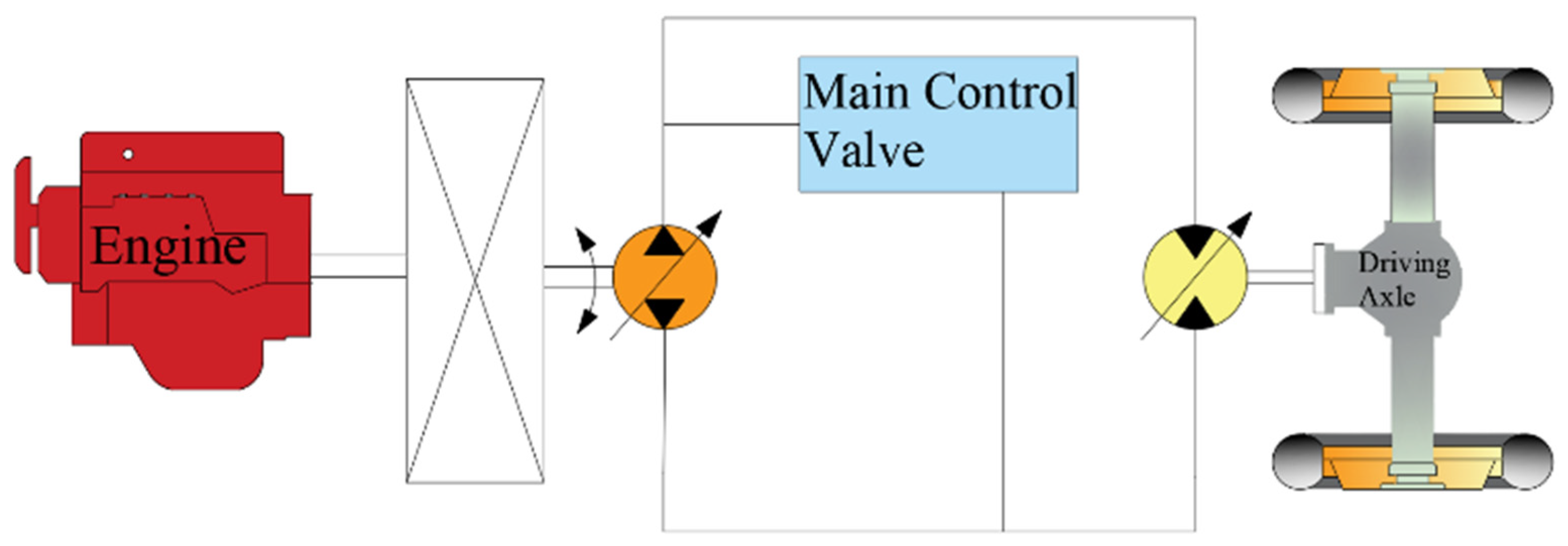
Hui Sun [35,36] conducted a comprehensive and in-depth study on the key technologies of quadratically regulated hydrostatic drive vehicles by applying quadratically regulated hydrostatic drive technology in the vehicle transmission system to realize energy recovery and reuse. Qingsong Lu [37] applied secondary regulation hydrostatic drive technology to a hydraulic lift device, whose hydraulic system is shown in Figure 7. When the lift is in deceleration braking, the hydraulic pump/motor works in the hydraulic pump condition, recovering the kinetic energy of the lift braking, and the pump will break the energy stored in the accumulator. When the lift is in the descending condition, the pressure is changed by the hydraulic transformer, and the hydraulic energy is stored in the accumulator. When the lift is in the ascending condition, the hydraulic pump/motor works in the motor condition, and the motor will drive the lift up through the control system; meanwhile, the recovered hydraulic pressure can provide auxiliary power for the vehicle, which can keep the engine working in the best economic zone, thus realizing energy recovery and utilization, which improves the fuel economy of the engine and reduces the throttling energy loss compared with the traditional valve control system to achieve higher efficiency and energy saving effects. Yang Liu [38] et al. conducted simulation experiments on a similar constant pressure network hydraulic system. The simulation showed that the kinetic energy added to the slewing system by the recovered hydraulic energy amounted to 0.895 kJ, which is 15.83% of the kinetic energy of the entire slewing device, which realizes the recovery and reuse of energy.
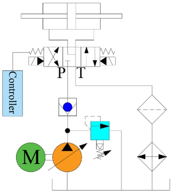
Figure 7.
Secondary regulation hydrostatic drive system.
Kim Heybroeka of Volvo Construction Equipment and Mika Sahlman of Norrhydro OY [39] proposed a new hydraulic tandem hybrid system based on a hydraulic accumulator, a secondary control motor, and a multi-chamber cylinder, whose system schematic is shown in Figure 8. The system employs a digital hydraulic pressure sensor for a double-acting multi-chamber cylinder to realize a stepwise variable displacement linear brake by skipping the step of converting the pressure. The system uses the CPR as the backbone of the system and all rotary actuators in the machine (slewing and track actuators) are based on secondary control motors. Four-quadrant operation is achieved using eccentric variable displacement hydraulic motors. The CPR serves as the foundation of the system, with all rotary drives within the machine (slewing and track drives) based on secondary control motors. Four-quadrant operation is achieved using eccentric variable displacement hydraulic motors. A valve manifold, mounted directly on the four-chamber cylinder, contains the necessary connections between its chambers and the CPR. On each connection, proportional valves are used to control the flow in and out of each cylinder chamber, potentially reducing energy losses by up to 60% compared to conventional load-sensing systems.
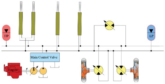
Figure 8.
New hydraulic tandem hybrid system.
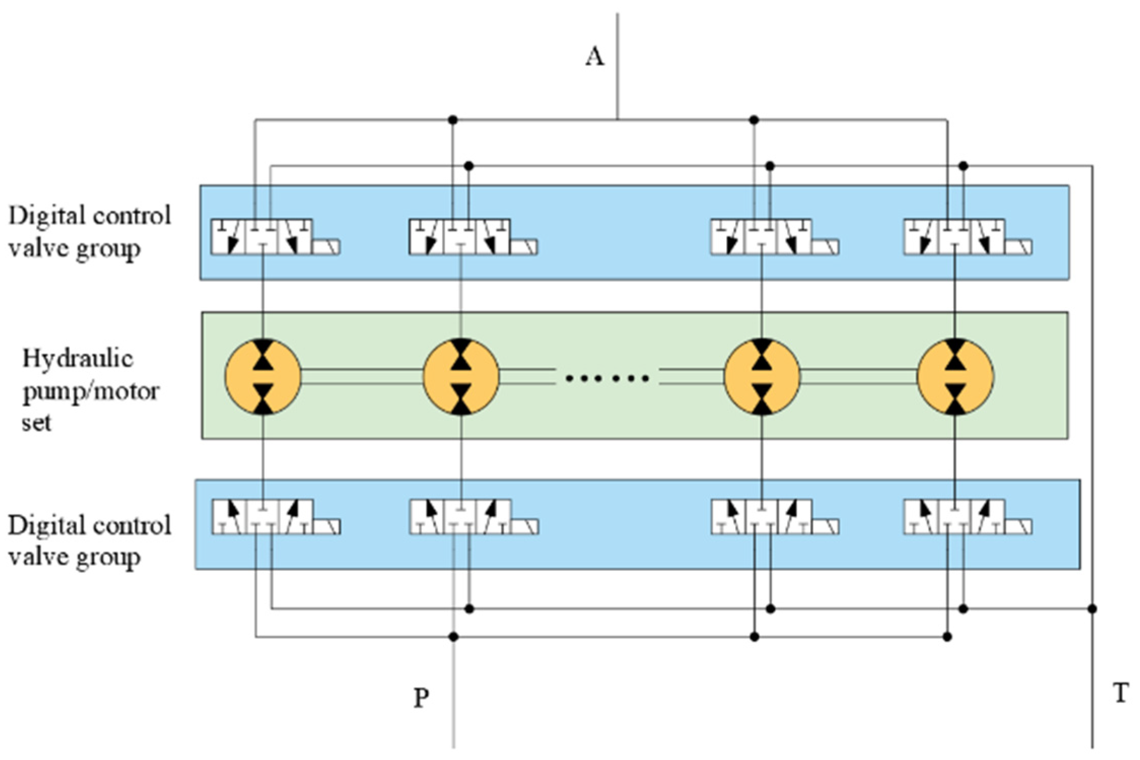
Yang Zhao of Yanshan University [40] applied digital technology and hydraulic technology together in a hydraulic transformer, designed a combined digital hydraulic transformer, and designed the transmission system for it, and its working principle diagram is shown in Figure 9. The middle frame line is a combination of several flow units, the top frame line is the outlet control valve group, and the bottom frame line is the inlet control valve group to control the flow direction of the fluid in each pump/motor unit and to complete the pump/motor unit in the different conditions of the conversion. The combined digital hydraulic transformer is composed of a pump/motor, relying on the transmission box gear drive pump/motor together to rotate. The pump/motor working condition is controlled by switching the switching state of the directional valve in the digital control valve group, so as to realize the pressure regulation of the digital hydraulic transformer.
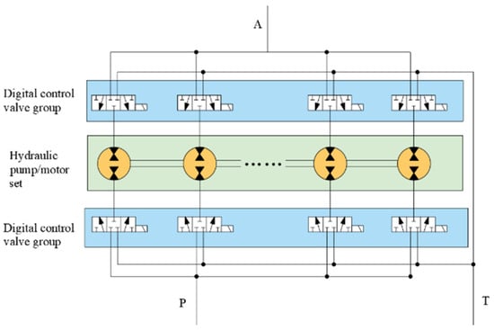
Figure 9.
Operating principle diagram of the combined digital hydraulic transformer.
Innas’ Peter Achten [41] and others proposed a new hydraulic transformer and designed a drive system for it. This hydraulic transformer introduces a CPR system and a secondary control method, which significantly reduces the energy losses associated with the hydraulic system and improves the pressure regulation range of the hydraulic transformer and the dynamic characteristics of the system.
The hydraulic transformer-based secondary regulation system divides the hydraulic system into two common high- and low-pressure pipelines. In the constant pressure network secondary regulation hydrostatic transmission, the secondary element directly obtains energy from the constant pressure network source without any energy loss in the middle of the process, and it can connect several respective independent loads at the same time to realize the recycling and reuse of the system’s kinetic energy and the potential energy of the heavy load. Adaptation to the load is accomplished by changing the transformer ratio of the hydraulic transformer, thus avoiding throttling losses [42], and energy storage is accomplished through positive load conditions. There is no interaction between system loads, and it has good controllability. And the system has high energy recovery efficiency, so it has broad development prospects. The key to further development lies in the improvement of the performance of secondary components and energy recovery components, including reliability, voltage regulation range, load adaptability, and transmission efficiency.
2.3. Adaptive Regulation System for Hydrostatic Transmission
In 2012, a professor from Tongji University Yongming Bian [43,44] proposed a fluid-controlled hydrostatic transmission system in which the variable pump displacement is controlled by a DA valve, and the variable motor is automatically controlled by HA high pressure. This system is adaptive, and with the change in vehicle load, the DA-HA control can realize the automatic adjustment of the displacement. Adaptive control of a bi-variable hydrostatic transmission system was investigated by Yan Wang, who proposed a control method to increase the response speed of the system and the efficiency of the system [45].
According to Prof. Matti Linjama of Tampere University of Technology, digital fluid power refers to hydraulic or pneumatic systems with discrete-valued components with active control system outputs [46]. According to Huayong Yang of Zhejiang University, hydraulic components with flow discretization or control signal discretization characteristics are called digital hydraulic components, and hydraulic systems with digital hydraulic component characteristics are called digital hydraulic systems [47,48]. Digital hydraulic technology can be divided into two branches: digital hydraulic technology based on parallel systems and digital hydraulic technology based on high-speed switching valves. The core of digital hydraulics based on high-speed switching valves is the high-speed switching valves, which control the output by means of pulse width modulation. Digital hydraulic technology based on parallel systems realizes discrete output through logic combination, does not rely on high-speed switching valves, has lower requirements for hydraulic components, cheaper construction costs, and has the advantages of large output flow and good reliability [49,50].
Matti Linjama of Tampere University [51] proposed a digital hydraulic excavator system by applying digital hydraulic valves to the work unit hydraulic system of a 20 t wheeled excavator. The authors performed D-IMV conversion of the moving arm, boom, bucket, and slewing actuators in a 21-ton Volvo EW210C wheeled excavator using a conventional hydrostatic system, and other actuators, such as the traveling function and auxiliary moving arm, were separated from the D-IMV system using proportional valves. And the excavator is equipped with an online monitoring module so that the flow rate at the pump outlet, the pressure in the actuator, supply line, return line, and the position of the actuator as well as the fuel consumption are monitored online. The pump unit is the same as the original machine with the addition of an electronic pressure relief valve to control the load-sensing pressure signal into the pump pressure controller. The original valve assembly was removed and the hydraulic joystick was replaced with an electronic one. The safety valves on the cylinders remained intact, but the control valves were replaced with electronic 3/2 proportional valves, reducing the energy loss of the converted D-IMV system by up to 10%, reducing input energy by 188 kJ, and increasing energy efficiency by 36%. However, in some modes, the system still requires an accumulator or another actuator to generate the flow required by the return line and to consume the flow generated by the supply line. Since the energy stored in the accumulator is related to the maximum and minimum pressures, a larger-volume accumulator is required to keep the system supplied with energy, thus increasing the size of the hydraulic system.
In order to solve this problem, Prabhat Ranjan [52] et al. proposed a hydraulic hybrid system with a pressurized accumulator with a PFCV. This problem was solved by the hydro-pneumatic accumulator, which has the same charge/discharge capacity as the actuator capacity. Therefore, no entropy is generated during the transfer of pressurized fluid to the low-pressure reservoir through the PRV. Compared to the conventional system, the energy consumption of the proposed system is reduced by 277 kJ without increasing the volume of the hydraulic system, and the energy efficiency is improved by 10%.
Yanshan University’s Tao Liu [53] proposed a pulse–width modulated digital hydraulic transformer based on high-speed switching valves and verified it using modeling simulation. Jilin University Chunshuang Li [54,55] analyzed the generation principle of the variable pressure shock of digital pumps, proposed an improvement method, applied the parallel digital pump to the steering hydraulic system of the wheel loader, and verified its feasibility through simulation and experiments. Zhejiang University Qingfeng Wang [56] et al. proposed a multi-pump multi-actuator hydraulic system, which was verified to have good stability as well as energy-saving effects through simulation. Yanshan University’s Dongting Jiang [57] et al. proposed a digital valve system with composite control of a switching manifold and a high-speed switching valve to realize an approximately continuously varying flow output.
Digital hydraulics is able to make up for the shortcomings of traditional hydraulic technology by reducing the number of components used for energy conversion between the energy source and the actuator, thus reducing energy loss, improving the efficiency of the system, and playing a greater role in smart factories and smart manufacturing. These characteristics have positioned parallel digital hydraulic technology as a prominent research area within the broader field of digital hydraulic technology. However, the lack of accurate and suitable control algorithms for parallel systems represents a significant challenge that has hindered the advancement of this technology [50], so it puts forward high requirements for the control system.
3. Control Strategies
The control strategy of the hydrostatic transmission system (HST) mainly solves the problem of energy loss and energy management. On the one hand, the energy transfer efficiency of the variable pump motor in HST is very high and the speed range is wide; on the other hand, the variable pump motor system is a highly coupled, nonlinear system, and pump motor decoupling control is very difficult. Through the appropriate segmented control mode, using segmented control to regulate the pump and the motor, respectively, it is possible to improve the control accuracy and response speed and reduce the system overflow so that the energy is transmitted more efficiently. The simple control strategy does not utilize the full potential of the hydrostatic drive system. At present, the traditional electro-hydraulic servo control strategy is being perfected, but with the traditional PID control combined with the application of a variety of control strategies, control technology is still in need of further development.
3.1. Torque Control Strategy
In mobile machinery, hydraulic transmission can provide smooth driving characteristics and a relatively good driving experience, while hydrostatic transmission can decouple the engine speed from the speed and torque to keep the engine in the theoretically optimal efficiency range, so torque control can reduce the excess torque from the engine for mobile machinery using the hydrostatic transmission system to achieve a comfortable driving experience [58]. Currently, engine torque control can be categorized into primary and secondary control [59].
3.1.1. Secondary Control
Secondary control was first proposed by KORDAK R [60] in 1981, and to this day, many scholars have added their own understanding of it [61,62], but the idea is basically the same: secondary control means that the pressure is set to the desired level, and the torque is controlled by the angle of rotation of the motor. A series of researchers have implemented secondary control in their applications, as evidenced by the literature. Among them, Salih Tetik and Michael Brand [63] proposed a method for the hydrostatic control of mobile machinery based on secondary control, where the architecture replaces the accumulator with a variable pressure so that the required pressure can be adjusted according to the system efficiency or actuating pressure, and the integration of the system is achieved using fewer components. It can also be applied to slewing control in traveling machinery to achieve energy recovery during the deceleration phase and in track drives to improve transmission performance. The secondary control architecture for driving and actuating hydraulics is shown in Figure 10.
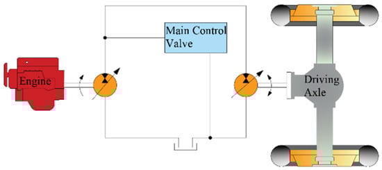
Figure 10.
Secondary control architecture for driving and actuating hydraulics.
In most cases, the simple secondary control uses a motor drive to control the direction of travel and the torque output from the hydraulic motor. The direction change of the traveling machinery can only be achieved by the change in the rotation angle of the hydraulic motor when the rotation angle is large enough to provide the torque required for direction change and reaches zero. At this point in time, a control valve is added so as to achieve smooth direction change of the vehicle. Secondary control is used in a large number of reciprocating traveling machines, but for specific reversing conditions, secondary control is not well matched to the characteristics of reciprocating motion.
3.1.2. Primary Control
Primary torque control was proposed by Steffen Mutschler, Norman Brix, and Yusheng Xiang [64] in 2008. Compared to secondary control, the same is the decoupling of the hydrostatic transmission control and torque control drive strategies, the difference is that the primary control controls the pressure by adjusting the rotation angle of the pump. Primary control provides a new solution for vehicle control, where researchers can apply old driveline parts to the new driveline without re-customization. At the same time, the adjustment of the hydrostatic system and the control strategy of the electrics is no longer dependent on the specific conditions of a traveling machine but on the macro-adjustment at the vehicle level.
The hydrostatic transmission system based on torque control relieves driving discomfort and improves the smoothness of the traveling machine motion to some extent. Because of the need to keep the engine in the theoretical optimal efficiency range, that is, only the optimization of engine efficiency is considered, less consideration to the optimization of the efficiency of the entire system. For safety reasons, the engine cannot shut down, so the overall energy conversion efficiency of the system reduces the overall transmission efficiency, and the optimal fuel economy cannot be achieved.
3.2. Fuzzy Control Strategy
Hydrostatic drive systems are highly nonlinear and susceptible to model changes [65], and the changing dynamic characteristics of hydrostatic drive speed control systems in turn require the controller to be constantly adaptive. Adaptivity can be achieved by changing the gain of the PI controller through fuzzy logic [66]. S. Tikkanen and K. Huhtala et al. of Tampere University of Technology proposed two controllers based on fuzzy logic control in 1995, and there is a prototype of the fuzzy control strategy applied to hydrostatic transmission systems.
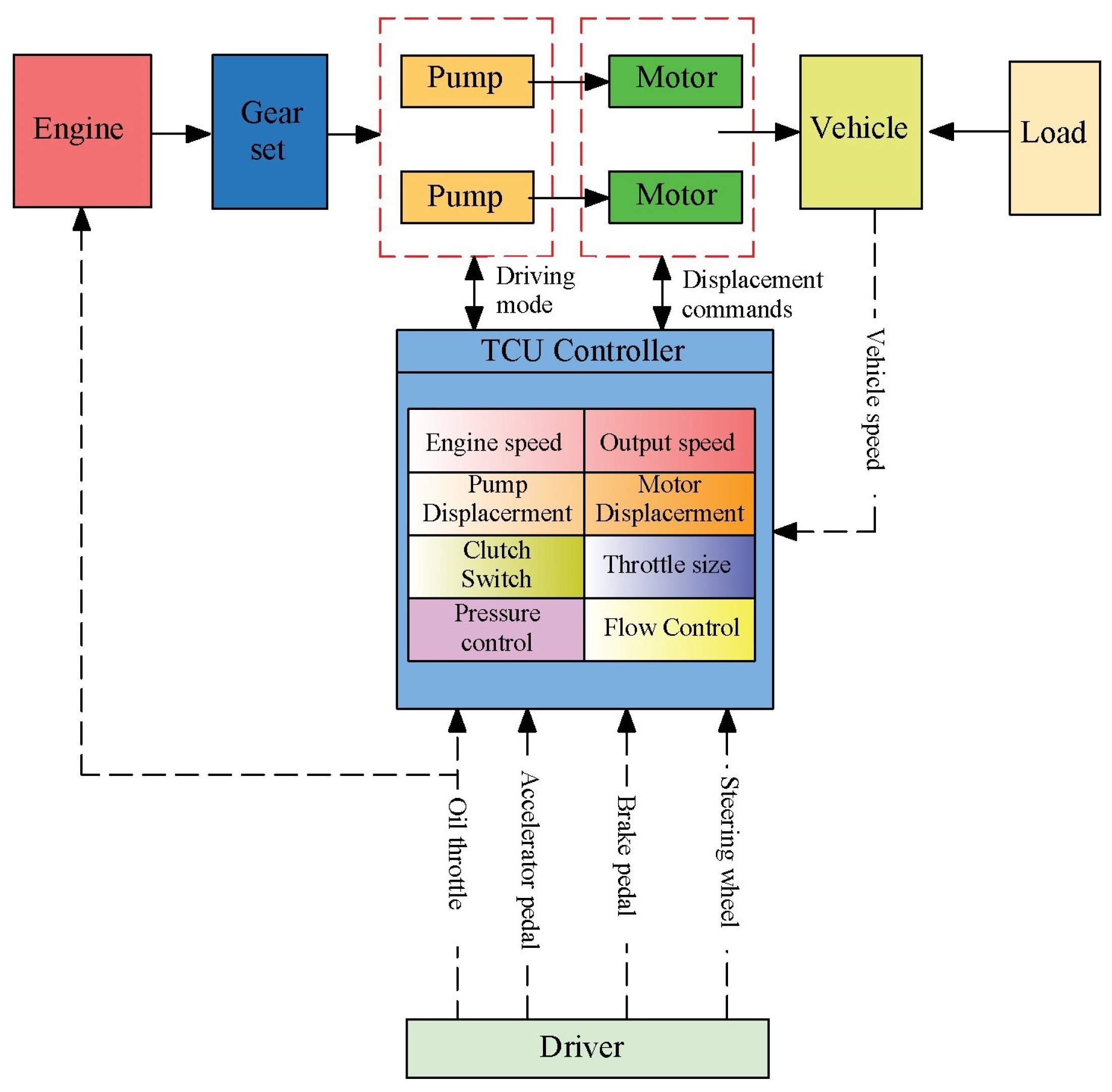
Jinle Zhang, Feihong Mao, and Jing Guo [27] proposed a fuzzy control based straight line driving strategy to meet the demand of tracked vehicles for the straight-line driving performance of hydrostatic transmission and, at the same time, it can ensure the stability of the vehicle’s forward driving; the control strategy is shown in Figure 11. The controller is responsible for interpreting the driver’s intention at each moment, as well as interpreting the operations of the accelerator pedal, brake pedal, steering wheel, and driving mode. Additionally, it provides target speeds for both motors. Conversely, the load resistance equivalent to the output torque on both sides of the motors exhibits a considerable degree of variability and a certain degree of randomness. Consequently, it is possible that one or both sides of the system may be unable to attain the desired speed. In such an event, it is essential that the controllers on both sides of the hydrostatic drive system are operated in a coordinated manner in order to realize the driver’s intention. The accelerator pedal is defined as the target vehicle speed, which is linearly correlated with the angular displacement of the accelerator pedal. This type of control requires interpreting control commands from multiple parts, and real-time control of the vehicle to maintain stability requires not only the controller’s algorithms but also a wealth of engineering experience to work with it, while existing control strategies have not yet taken into account changes in road gradient and other changes.

Figure 11.
Speed control strategy.
Hasan H. Ali, Ahmed W. Mustafa, and Fawaz F. Al-Bakri [67] designed a fuzzy PID control-based hydraulic cylinder speed control hydrostatic transmission system, and based on the PID controller, a hybrid sensitivity loop shaping H∞ (infinity) controller was also designed to improve the system’s immunity to disturbances while improving the system’s input tracking performance. Junlin Luo and Wei Wu [68] proposed a volumetric efficiency correction factor based on fuzzy control as well as speed ratio closed-loop feedback control to correct the theoretical displacement of the pump motor, thus proposing a pump motor displacement control strategy to achieve the maximum acceleration capability of the vehicle. Zelong Li [69] proposed a fuzzy PID control method according to the load change of the loader rocker arm linkage complex, which can adjust the control parameters in real time to ensure the accuracy of the cylinder piston positioning process, and the energy consumption of the variable-speed load-sensitive system with the application of this control strategy is 10.12% energy saving compared with the traditional pump control system. Mengxiang Wang [70] proposed a fuzzy feed-forward–feedback control strategy based on fuzzy control, which takes the normalized steering wheel angle and its rate of change input from the driver model as the fuzzy feed-forward control input to compensate for the hydraulic system displacement ratio and takes the deviation of the actual steering radius from the target steering radius and its rate of change as the fuzzy feedback control input to correct the hydraulic system displacement ratio. The deviation of the actual steering radius from the target steering radius and its change rate are used as the fuzzy feedback control input to correct the hydraulic system displacement ratio, so as to achieve compensation correction for the speed of both sides of the track. By realizing the test, the dynamic response time of steering for the small-radius steering condition was shortened by 0.12 s, and the turning efficiency was improved by 15.38%, while the dynamic response time of steering for the large-radius steering condition was shortened by 0.07 s, and the turning efficiency was improved by 17.07%, and the stability of the steering trajectory was also improved.
Xin Wang, Zhongyu Wang [71], and others proposed a multivariate control strategy based on fuzzy sliding mode control. Their simulation results showed that the proposed control strategy is well matched with the system and can actively adapt to disturbances. The field test results demonstrate that the scheme is capable of facilitating seamless automatic gear shifting of the wheel loader while effectively regulating the system pressure, flow, and power. In comparison with the conventional torque converter loader transmission system, its transmission efficiency has been shown to be enhanced by 30%, and in comparison to the traditional hydrostatic transmission system, the efficiency was enhanced by 8%.
The dynamic characteristics of hydrostatic transmission systems are often nonlinear [72], and for nonlinear time-varying and mathematical models that are difficult to calculate accurately, the fuzzy control strategy has good regulation performance and can achieve a good control effect. Generally, the energy storage state of the energy storage element, the demand torque, the rotational speed, and other parameters are used as the input signals of the control system, and the fuzzy controller queries the relevant rules in the rule base based on expert experience according to the input signals, in order to calculate the output torque and rotational speed of each power source, so as to allocate the energy. The advantage of the fuzzy control strategy is the ability to deal with the control rules that cannot be expressed by precise parameters, which can not only optimize the engine operating point but also optimize the energy storage element, power element, and transmission element, etc., to achieve compromise between each part, so as to optimize the fuel economy and emissions of the entire engine [73]. However, the determination of fuzzy rules necessitates a substantial degree of engineering expertise, rendering the intuitive identification of optimal rules a challenging endeavor. In the context of control, the domain and control law of each variable are fixed and unable to undergo automatic adjustments in response to varying operational conditions. This significantly constrains the dynamic characteristics of the system. The current research trajectory involves the integration of fuzzy control strategies with optimization algorithms, such as neural networks and genetic algorithms, to develop a composite control strategy with enhanced optimization capabilities.
3.3. Optimization Control Strategy
Optimization-based control strategies are suitable for systems that experience difficulty in obtaining accurate mathematical models [74], and they are especially well adapted for systems such as construction machinery with complex structures, variable working conditions, and difficulty in finding the optimal operating point to satisfy the performance requirements of the entire machine according to the establishment of control methods with fixed thresholds. At present, more adaptive, predictive, and particle swarm optimization control strategies are used, while predictive and dynamic planning control strategies are mostly used in construction machinery such as transportation machinery in earth-moving machinery.
Jilin University’s Wenchao Li [75] proposed a parallel digital pump/motor hydrostatic transmission system utilizing adaptive control; the proposed control system uses an acceleration mode control strategy for the acceleration problem in the digital hydraulic pump/motor hydrostatic transmission system, an external load adaptive control strategy based on the segmented control of the digital pump/motor, an external load adaptive control strategy based on the cost function and bi-variable control for external load adaptive, and a switching timing control strategy for the negative impact of the upshift motor speed. For the external load adaptive control strategy, the switching timing control strategy is proposed for the negative impact of upshift motor speed. Zhikai Yao of Nanjing University of Science and Technology [76] proposed an asymptotic tracking control strategy for hydraulic systems based on an adaptive perturbation observer, which combines online learning adaptive control with a perturbation observer to obtain better tracking performance of the hydraulic system. The advantage of this control algorithm is that it is capable of simultaneously addressing parameter uncertainties and time-varying perturbations, thereby achieving global asymptotic stabilization when the system is subjected to mismatch or matching perturbations. However, in practical applications, full-state feedback cannot be obtained due to cost and other factors.
The University of Rostock’s Dang Ngoc Danh [77] and others put forward a model predictive control strategy with multiple control inputs, which realizes the real-time tracking control of desired angular velocity or desired hydraulic torque. Simulation and experimental results show that the realized nonlinear control structure has high accuracy and good performance, which can effectively counteract the model uncertainty and external disturbances. Southwest University of China’s Liping Yao [78] and others proposed a model predictive control strategy applicable to hydrostatic transmission (HST) control systems. In order to be able to make an energy allocation decision for the next moment, it is necessary to predict the information of future conditions, then optimize the economy of this predicted section of conditions, and finally determine the control command for the next moment [79]. Using simulation and bench experiments, it was found that by utilizing this strategy, the HST can quickly reach the desired speed at different step speeds with a small amount of overshoot and enter the steady state with a small speed fluctuation. It can stabilize the output speed of the HST during sudden load changes, suppress the speed fluctuations due to load changes, and enhance the robustness of the system. Most of the existing predictive control strategies are proposed for hybrid transportation machines, and their shortcomings are that the overall efficiency will be much lower if the actual working conditions deviate greatly from the predicted conditions. At the same time, the existing control strategies do not take into account the changes in the mass of the transportation machine and the slope of the road.
Yong You of Chongqing University [80] et al. optimized a new hydro-mechanical power return transmission device for wheel loaders and used particle swarm optimization algorithms to control it, which can effectively enhance system efficiency while ensuring optimal power performance. Through the simulation of the system, a comparison of the data revealed that in traditional transportation machinery, the transmission efficiency of the system was enhanced by 2.06%, which has the effect of reducing fuel consumption while maintaining the desired power performance. M. Bhola [81] and others developed a multi-degree-of-freedom energy management controller using machine learning algorithms for the energy management of closed-circuit hydrostatic drives in front-end loader (FEL) machines. The goal of the energy management controller is to keep the prime mover, pump, and hydraulic motor in their effective regions regardless of the change in load speed at the drive end. A comparative study of two- and three-degrees-of-freedom-controlled drivelines experimentally showed that the engine fuel consumption of the three-degrees-of-freedom-controlled driveline was reduced by 34% compared to the two-degrees-of-freedom-controlled driveline, and the overall driveline efficiency was relatively improved by 20–30%. The tracking performance of the HST system can be further improved by utilizing machine learning techniques [82], and the learning control has high robustness, accuracy, and simplicity of control design.
Optimization-based control strategies are hydrostatic transmission control strategies developed by applying optimization methods and optimal control theory. Most of the current optimization control strategies applied to hydrostatic transmission systems belong to the global optimization control strategy, which starts from the fuel economy of the entire aircraft and takes the state obtained by the system as a variable constraint mathematical model, and a good power distribution control strategy can be obtained by the algorithm. At present, this optimization algorithm cannot be directly used in actual working conditions, because for the airborne system, the performance and hardware constraints as well as the various complex scenarios of the actual working conditions require high computational costs, which may limit the use of this strategy, and it can only be temporarily used in standard working conditions to evaluate the existing real-time control strategy and combine to form a practical real-time optimization strategy.
4. Discussion
From the above analysis, it can be seen that the focus of hydrostatic transmission system design is still to reduce the loss of energy within the hydraulic system. There are two common methods to reduce energy loss: reducing the loss of energy in the transfer process of the system and reducing the loss of energy in the conversion process of secondary components.
Currently, the hydrostatic transmission used in construction machinery mostly uses valve control systems to regulate pressure and flow, resulting in greater energy losses. As a way to reduce energy transfer losses, one can use a pump control system instead of a valve control system, use of pump motor system to control the pressure and flow of the system, simplify the energy transfer path, or use a secondary regulation system, adaptive regulation system, or digital hydraulics and other technologies to reduce the number of components between the actuator and the source of energy to make up for the shortcomings of the traditional hydraulic technology.
Hydrostatic drive systems utilize the conversion between the internal energy of the liquid (pressure potential energy) and the mechanical energy, and most of them still use accumulators and batteries together as energy storage elements, with the hydraulic system providing the peak power and the electric system providing a part of the installed engine power [81], resulting in a consequent loss of a large amount of energy brought about by the conversion of the energy between the two systems (the hydraulic system and the electric system). They can therefore be considered to optimize the performance of the accumulator to obtain a higher power density and a fast enough response time for charging and discharging energy or to find alternative energy storage elements.
The optimization of the control strategy is also one of the important means to improve the fuel economy of hydrostatic transmission systems. After years of development, hydrostatic transmission systems have formed a series of more perfect control strategies, which can be specifically divided into traditional control strategies and modern control strategies: one is the rule-based traditional control strategy [82] and the other is the optimization-based modern control strategy [83].
The traditional rule-based control strategy is mainly based on the proportional-integral-derivative (PID) control theory, and the core idea is to make the system output track the desired input by adjusting the three parameters of the controller: proportional, integral, and differential. In hydrostatic transmission systems, the desired output is usually a constant speed or torque, while the actual output of the system will be affected by a variety of factors, such as load changes, system disturbances, etc. The role of the PID controller is to make the system output as close as possible to the desired value by constantly adjusting the control signal. Although good control results have been achieved in hydrostatic transmission systems, there are some limitations at the same time. For example, the PID control strategy requires an accurate system model and parameters; otherwise, the control effect will be affected.
Modern control strategies based on optimization provide more options and possibilities for the control of hydrostatic transmission systems. Modern control theory is a control method developed on the basis of classical control theory. It utilizes advanced mathematical tools, such as linear algebra back, the state space method, optimal control, etc., to deal with the nonlinear, time-varying, and multivariate problems of the system. A common modern control strategy is fuzzy control. This control strategy does not require an exact mathematical model and is suitable for nonlinear, time-varying, and uncertain systems. In hydrostatic transmission systems, fuzzy control can be effective in controlling them due to their complex internal mechanisms. The core of fuzzy control is fuzzy logic, which fuzzifies the inputs and outputs and then derives the control signals through fuzzy reasoning. This control strategy has strong robustness and can be adapted to a variety of different working conditions. Another modern control strategy is adaptive control. Adaptive control is a control method that can automatically adjust the controller parameters to adapt to system dynamic changes and external disturbances. In a hydrostatic transmission system, the parameters of the system change due to changes in load and changes in operating conditions. The adaptive controller is able to adjust the parameters in real time to maintain the stability and performance of the system. This control strategy is highly adaptive and can cope with various complex working environments.
However, these theories do not exist in isolation but cross and integrate with each other. In practical control applications, the appropriate theories and algorithms are often selected according to specific circumstances or combined with a variety of methods for integrated control. The fuzzy reasoning and fuzzy rules are combined in fuzzy control theory with the classical PID controller area. Fuzzy logic is used to adjust the PID parameters according to the system state, so as to realize the adaptive control of the system. The neural network and optimal control theory are combined and the neural network is used to learn the dynamic behavior of the system and optimize it as an objective function, so as to realize the optimal control of the system. The state space model and model predictive control methods in modern control theory are combined with adaptive control in intelligent control theory. Through online identification and model prediction, the controller parameters are adjusted in real time to adapt the control system to system changes and external disturbances. Combining reinforcement learning and modern control theory, a reinforcement learning algorithm is used to learn the optimal control strategy adopted by the system in different states. Through the interaction with the environment and the design of the reward function, the control system can learn and optimize the control strategy autonomously. In the following table, Table 2, the optimization and development direction of hydrostatic transmission systems and control strategies are shown.
Table 2.
Optimization and development of hydrostatic transmission systems and control strategies.
5. Conclusions
It can be seen that compared with the hydro-mechanical transmission system, there is still a lot of room for the development of control strategies in the field of hydrostatic transmission systems. In addition to the use of a hydrodynamic transmission system vehicle control strategy, the oil–hydraulic hybrid construction machinery control strategy can also be used as a reference. Due to the wide variety of transmission methods of construction machinery, it should still be based on a specific system from the targeted development of control strategies suitable for hydrostatic transmission systems. At the same time, the hydrostatic transmission system control objectives should not be limited to reducing fuel consumption and emissions but should also consider the optimization of the system, such as system vibration control and noise suppression.
The development direction of hydrostatic transmission system engineering machinery mainly includes the following aspects: (1) utilizing the mature technology of absorbing, storing, and regenerating braking energy, it is further developed into an oil–liquid hybrid power system with good energy-saving effects; (2) the use of artificial intelligence technology to realize the hydrostatic transmission system’s adaptive control and fault diagnosis; (3) the use of network technology to realize the remote monitoring and maintenance of the hydrostatic transmission system; (4) adopting green design concepts to improve the energy utilization efficiency of hydrostatic transmission systems and reduce environmental pollution; and (5) intelligentization of the hydrostatic transmission system.
Author Contributions
Conceptualization, R.L. and Q.F.; methodology, J.Z.; software, Q.F.; investigation, Q.F.; resources, R.L.; data curation, J.Z.; writing—original draft preparation, Q.F.; writing—review and editing, R.L.; visualization, T.F.; supervision, T.F.; project administration, R.L.; funding acquisition, R.L. All authors have read and agreed to the published version of the manuscript.
Funding
This research was funded by the Key R&D plan of Shandong Province, grant number 2022CXGC020702; the Research and Development of Key Technology of Intelligent Steering System for Large Tractors, grant number SKLIAPE2023017; and the Key R&D plan of Shandong Province, grant number 2021CXGC010813.
Data Availability Statement
Not applicable.
Acknowledgments
We would like to thank our tutor, Ruichuan Li, for all of his support and guidance. Qingkai Fan would like to thank their colleagues for their care and help in their daily work.
Conflicts of Interest
Juxin Zhang is employed by the State Key Laboratory of Intelligent Agricultural Power Equipment, Tongxian Fan is employed by the Zoucheng Yishan High School, and the remaining authors declare that the research was conducted in the absence of any commercial or financial relationships that could be construed as a potential conflict of interest.
References
- Mahato, A.C.; Ghoshal, S.K. An Overview of Energy Savings Approaches on Hydraulic Drive Systems. Int. J. Fluid Power 2020, 21, 81–118. [Google Scholar] [CrossRef]
- Wang, Y. Hydraulic combination transmissions technology in mobile machinery. Hydraul. Pneum. Seals 2004, 1, 18–23. [Google Scholar]
- Xiong, S.; Wilfong, G.; Lumkes, J., Jr. Components Sizing and Performance Analysis of Hydro-Mechanical Power Split Transmission Applied to a Wheel Loader. Energies 2019, 12, 1613. [Google Scholar] [CrossRef]
- Li, Z.H.; Zhu, Q.M.; Mo, X.C. Development and Trend of Loader Transmission Technology. Hydraul. Pneum. Seals 2021, 41, 7–9+17. [Google Scholar]
- Jha, A.K.; Gupta, A.K.; Singh, S.; Singh, S.K. A Review on Hybrid Electric Vehicles and Power Sources. In Proceedings of the 2022 2nd International Conference on Emerging Frontiers in Electrical and Electronic Technologies (ICEFEET), Patna, India, 24–25 June 2022. [Google Scholar]
- Schmidt, L.; Hansen, K.V. Electro-Hydraulic Variable-Speed Drive Networks—Idea, Perspectives, and Energy Saving Potentials. Energies 2022, 15, 1228. [Google Scholar] [CrossRef]
- Jiang, Z.H.; Xia, C.G. Study on Characteristic of Hydrostatic Transmission System of Tractor. J. Agric. Mech. Res. 2021, 43, 249–254. [Google Scholar]
- Guo, T.; Wu, B.; Lin, T.; Chen, H.; Chen, Q. Closed-Circuit Pump-Controlled Electro-Hydraulic Steering System for Pure Electric Wheel Loader. Appl. Sci. 2022, 12, 5740. [Google Scholar] [CrossRef]
- Hong, P. PERMCO Open Loop Hydraulic Vibration System for Vibratory Road Roller. Hydraul. Pneum. Seals 2022, 42, 84–87. [Google Scholar]
- Zhang, Y.T.; Wang, Q.F.; Xiao, Q. Simulation and Experimental Research on Energy Regeneration with Hydraulic Motor for Hybrid Drive Excavator. J. Mech. Eng. 2007, 8, 218–223+228. [Google Scholar] [CrossRef]
- Yan, L.J.; Sun, H.; Liu, W.; Jiang, J.H.; Zhao, Y.; Han, J.W. Hydraulic hybrid technology of moving construction machinery. J. Jilin Univ. (Eng. Technol. Ed.) 2014, 44, 364–368. [Google Scholar]
- Ding, R.Q.; Yin, H.Z.; Cheng, M.; Li, G.; Xu, B. The design and analysis of a hydro-pneumatic energy storage closed-circuit pump control system with a four-chamber cylinder. J. Energy Storage 2024, 79, 110076. [Google Scholar] [CrossRef]
- Zuo, D.L. Study on Hydrostatic Transmission Control System. Master’s Thesis, Nanjing Agricultural University, Nanjing, China, June 2009. [Google Scholar]
- Jiang, H. Research on Drive System of Hydrostatic Transmission Vehicle. Master’s Thesis, Beijing Institute of Technology, Beijing, China, January 2016. [Google Scholar]
- Zhao, J. Research and application of hydrostatic transmission device for agricultural machinery. J. Agric. Mech. Res. 2000, 12, 99–101. [Google Scholar]
- Wang, H.; Yang, S.; Lu, T. Mechanical transmission system of loader based on hydraulic hybrid technology. Therm. Sci. 2021, 25, 4233–4240. [Google Scholar] [CrossRef]
- Sheng, Y.; Escobar-Naranjo, D.; Stelson, K.A. Feasibility of Hydrostatic Transmission in Community Wind Turbines. Actuators 2023, 12, 426. [Google Scholar] [CrossRef]
- Ma, J.; Sun, S.Z.; Rui, H.T. Review on China’s Road Construction Machinery Research Progress: 2018. China J. Highw. Transp. 2018, 31, 1–164. [Google Scholar]
- Yang, S.J.; Chu, J.J.; Peng, Z.X.; Li, X.L.; Shi, Z.X.; Zhang, Z.L. Online identification method for wheel loader working conditions with hydro-mechanical continuously variable transmission. Trans. Chin. Soc. Agric. Eng. 2022, 38, 1–11. [Google Scholar] [CrossRef]
- Ho, T.H.; Ahn, K.K. Modeling and simulation of hydrostatic transmission system with energy regeneration using hydraulic accumulator. J. Mech. Sci. Technol. 2010, 24, 1163–1175. [Google Scholar] [CrossRef]
- Ma, Y.B.; Zhao, B.; Hao, Y.X. Characteristics Analysis of Asymmetric Pump-controlled Single-rod Hydraulic Cylinder System. Chin. Hydraul. Pneum. 2020, 8, 167–175. [Google Scholar]
- Ge, L.; Zhang, X.G.; Quan, L.; Wang, C.B.; Wu, L.S. Experiment Study on the Characteristics of Speed-variable Asymmetric Pump Driven Excavator Arm. J. Mech. Eng. 2017, 53, 210–216. [Google Scholar] [CrossRef]
- Pandey, A.K.; Dasgupta, K.; Kumar, N. Steady-state performance investigation of closed-circuit hydrostatic drive using variable displacement pump and variable displacement motor. Kuwait J. Sci 2019, 46, 76–83. [Google Scholar]
- Yang, W.W. Research on Walking Speed Control and System Flow Matching of Electric Hydrostatic Transmission Forklift. Master’s Thesis, Southwest Jiaotong University, Chengdu, China, 2020. [Google Scholar]
- Yang, W.W.; Ke, J.; Yang, Z.J.; Wang, Y.X.; Li, L.Z. Design and Simulation of Hydrostatic Transmission System in Electric Forklift. Mach. Tool Hydraul. 2020, 48, 71–75. [Google Scholar]
- Huang, W.L. Research on Hydrostatic Drive System of Grain Combine Harvester. Master’s Thesis, Henan University of Science and Technology, Luoyang, China, 2022. [Google Scholar]
- Zhang, J.; Mao, F.; Guo, J. Research on straight driving strategy of tracked vehicle equipped with hydrostatic transmission. In Proceedings of the 2017 2nd International Conference on Robotics and Automation Engineering (ICRAE), Shanghai, China, 29–31 December 2017. [Google Scholar]
- Wang, S.L.; Liu, Q.; Ma, W.X.; Liu, C.B.; Li, J. Simulation Analysis and Experimental Study on Characteristics for Loader Traveling Hydrostatic Transmission System. Hydraul. Pneum. Seals 2019, 39, 34–39+43. [Google Scholar]
- Zhang, S.Z.; Liu, Y.; Zheng, X.P.; Zhang, X.F. Performance Analysis of Single and Double Pump-controlled Distributed Hydraulic System for Excavator. Chin. Hydraul. Pneum. 2024, 48, 117–123. [Google Scholar]
- Manring, N.D.; Fales, R.C. Hydraulic Control Systems, 2nd ed.; Wiley Online Library: Hoboken, NJ, USA, 2019; pp. 293–343. [Google Scholar]
- Fussner, D.; Wendel, G.; Wray, C. Analysis of a Hybrid Multi-Mode Hydro-mechanical Transmission. SAE Tech. Pap. 2007, 1, 1455. [Google Scholar]
- Chuma, O.N.A. Energy recovery and management in pressure coupled hydraulic hybrid bus using new hydraulic transformer and clean diesel combustion engine. In Proceedings of the Seventh International Conference on Fluid Power Transmission and Control, Hangzhou, China, 7–10 April 2009. [Google Scholar]
- Werndin, R.; Achten, P.; Sannelius, M.; Palmberg, J. Efficiency performance and control aspects of a Hydraulic Transformer. In Proceedings of the Sixth Scandinavian International Conference on Fluid Power, Tampere, Finland, 26–28 May 1999. [Google Scholar]
- Moreno, M.A.; Carrion, P.A.; Planells, P.; Ortega, J.F. Measurement and improvement of the energy efficiency at pumping stations. Biosyst. Eng. 2007, 98, 479–486. [Google Scholar] [CrossRef]
- Wang, X.; Jiang, J.H. Regenerative braking control strategy for wheel drive hydraulic hybrid vehicle. J. Jilin Univ. (Eng. Technol. Ed.) 2008, 6, 248–252. [Google Scholar]
- Sun, H.; Jiang, J.H.; Wang, X. Parameters Matching and Control Method of Hydraulic Hybrid Vehicles with Secondary Regulation Technology. Chin. J. Mech. Eng. 2009, 22, 57–63. [Google Scholar] [CrossRef]
- Lu, Q.S. Energy-Saving Analysis of Secondary Regulation Technology Applied to Hydraulic Lifting Device. Master’s Thesis, University of South China, Hengyang, China, 2018. [Google Scholar]
- Liu, Y.; Li, L.; Lu, Q.S. Accumulator Recovery System of Hydraulic Excavator Based on AMESim. Mech. Res. Appl. 2018, 31, 26–28+33. [Google Scholar]
- Heybroek, K.; Sahlman, M. A hydraulic hybrid excavator based on multi-chamber cylinders and secondary control—Design and experimental validation. Int. J. Fluid Power 2018, 19, 91–105. [Google Scholar] [CrossRef]
- Zhao, Y. Research on Combine Digital Hydraulic Transformer. Master’s Thesis, Yanshan University, Qinhuangdao, China, 2019. [Google Scholar]
- Peter, A.; Jeroen, P.; Sef, A.; Jasper, A.; Robin, M. The Design of The FCT80 Hydraulic Transformer. In Proceedings of the 18th Scandinavian International Conference on Fluid Power, Tampere, Finland, 30 May–1 June 2023. [Google Scholar]
- Wang, Z.; Liu, X.; Qiu, Z.; Jiao, Z. Research on the flow characteristics of the secondary regulation aircraft weapon bay door drive system with accumulator. In Proceedings of the CSAA/IET International Conference on Aircraft Utility Systems (AUS 2022), Nanchang, China, 17–20 August 2022. [Google Scholar]
- Bian, Y.M.; Ning, X.X.; Zhao, F.W.; Li, S.B. Applying DA-HA close-loop control system for construction machinery. Chin. J. Constr. Mach. 2012, 10, 58–63. [Google Scholar]
- Bian, Y.M.; Xie, C. Simulation and Research of Electro-hydraulic Proportional Flow Control Valve in Hydraulic Lifting Systems Based on Amesim. Mechatronics 2009, 15, 56–59. [Google Scholar]
- Wang, Y. Variable structure control for variable pump controlling variable motor. J. Beijing Univ. Aeronaut. Astronaut. 2010, 36, 1453–1456. [Google Scholar]
- Linjama, M. Digital fluid power—State of the art. In Proceedings of the Twelfth Scandinavian International Conference on Fluid Power, Tampere, Finland, 18–20 May 2011. [Google Scholar]
- Yang, H.Y.; Wang, S.; Zhang, B.; Hong, H.C.; Zhong, L. Development and prospect of digital hydraulic valve and valve control system. J. Jilin Univ. (Eng. Technol. Ed.) 2016, 46, 1494–1505. [Google Scholar]
- Zhong, L. Research on Key Technologies of Programmable Valve. Ph.D. Thesis, Zhejiang University, Hangzhou, China, 2019. [Google Scholar]
- Sciatti, F.; Tamburrano, P.; Distaso, E.; Amirante, R. Digital hydraulic valves: Advancements in research. Heliyon 2024, 10, e27264. [Google Scholar] [CrossRef] [PubMed]
- Zhang, Q.; Kong, X.; Yu, B.; Ba, K.; Jin, Z.; Kang, Y. Review and Development Trend of Digital Hydraulic Technology. Appl. Sci. 2020, 10, 579. [Google Scholar] [CrossRef]
- Linjama, M.; Huova, M.; Tammisto, J.; Heikkilä, M.; Tikkanen, S.; Kajaste, J.; Paloniitty, M.; Pietola, M. Hydraulic hybrid working machines project—Lessons learned. In Proceedings of the 16th Scandinavian International Conference on Fluid Power (SICFP 2019), Tampere, Finland, 22–24 May 2019. [Google Scholar]
- Ranjan, P.; Wrat, G.; Bhola, M.; Mishra, S.K.; Das, J. A novel approach for the energy recovery and position control of a hybrid hydraulic excavator. ISA Trans. 2020, 99, 387–402. [Google Scholar] [CrossRef]
- Liu, T.; Han, Y.; Li, H.; Zhao, D.X. Design and Simulation of PWM Hydraulic Transformer. Mech. Sci. Technol. Aerosp. Eng. 2022, 41, 1753–1758. [Google Scholar]
- Li, C.S. Research on Control Characteristics and Application of Digital Pump Based on Discrete Variable Technology. Ph.D. Thesis, Jilin University, Jilin, China, 2022. [Google Scholar]
- Li, C.; Wang, X.; Qi, H.B.; Liu, X.Y.; Liu, X.H. Pressure performance improvement by dual-mode control in digital pump/motor. J. Cent. South Univ. 2020, 27, 2628–2642. [Google Scholar] [CrossRef]
- Bao, R.; Wang, Q.; Wang, T. Modeling and control strategy of a multi-pump multi-actuator hydraulic system with on/off valve matrix. IEEE Access 2020, 21, 156–166. [Google Scholar]
- Jiang, D.T. Research on Digital Valves Group Controlled by PWM and PCM. Master’s Thesis, Yanshan University, Qinhuangdao, China, 2020. [Google Scholar]
- Xiang, Y.S.; Mutschler, S.; Brix, N.; Brach, C.; Geimer, M. Optimization of hydrostatic-mechanical transmission control strategy by means of torque control. In Proceedings of the 12th International Fluid Power Conference, Dresden, Germany, 9–11 March 2020. [Google Scholar]
- Murrenhoff, H. Servohydraulik—Geregelte Hydraulische Antriebe; Shaker Verlag GmbH: Aachen, Germany, 2008. [Google Scholar]
- Kordak, R. Neuartige Antriebskonzeption mit sekundärgeregelten hydrostatischen Maschinen. Oelhydraulik Pneum. 1981, 25, 387–392. [Google Scholar]
- Bauer, G.; Niebergall, M. Ölhydraulik: Grundlagen, Bauelemente, Anwendungen; Springer Vieweg Wiesbaden: Wiesbaden, Germany, 2016; pp. 221–229. [Google Scholar]
- Backé, W. Verlustarme hydrostatische Antriebe. Grundlagen und Anwendungen. VDI Berichte-Ver. Dtsch. Ingenieure 1994, 1132, 147–166. [Google Scholar]
- Tetik, S.; Bran, M. Secondary Control Based Hydraulic Architectures for Mobile Applications. In Proceedings of the 13th International Fluid Power Conference, Aachen, Germany, 13–15 June 2022. [Google Scholar]
- Mutschler, S.; Brix, N.; Xiang, Y. Torque Control for Mobile Machines. In Proceedings of the 11th International Fluid Power Conference, Aachen, Germany, 19–21 March 2018. [Google Scholar]
- Njabeleke, I.A.; Pannett, R.F.; Chawdhry, P.K.; Burrows, C.R. Self-organising fuzzy logic control of a hydrostatic transmission. In Proceedings of the UKACC International Conference on CONTROL’98 (IEE Conf. Publ. No.455), Swansea, UK, 6 August 1998. [Google Scholar]
- Tikkanen, S.; Huhtala, K.; Vilenius, M. Fuzzy controllers in hydrostatic transmission. In Proceedings of the IEE Colloquium on Innovative Actuators for Mechatronic Systems, London, UK, 18 October 1995. [Google Scholar]
- Ali, H.H.; Mustafa, A.W.; Al-Bakri, F.F. A new control design and robustness analysis of a variable speed hydrostatic transmission used to control the velocity of a hydraulic cylinder. Int. J. Dynam. Control 2021, 9, 1078–1091. [Google Scholar] [CrossRef]
- Luo, J.L.; Wu, W.; Zou, T.G.; Yuan, S.H.; Wei, C.H. Study on Dynamic Characteristics of Hydrostatic Driven Vehicle Acceleration Process. J. Mech. Eng. 2023, 59, 254–262. [Google Scholar]
- Li, Z.L. Research on Characteristics of Hydraulic System of Construction Machinery Controlled Independently by Fuzzy PID at Inlet and Outlet. Master’s Thesis, Taiyuan University of Technology, Taiyuan, China, 2022. [Google Scholar]
- Wang, M.X.; Cao, F.Y.; Zhu, X.J.; Xu, L.Y. Research on hydro-mechanical differential steering control strategy of tracked vehicle. Mod. Manuf. Eng. 2023, 1, 50–56. [Google Scholar]
- Wang, X.; Wang, Z.; Xie, L.; Wang, S.; Wang, Z.; Ma, W. Research on the New Hydrostatic Transmission System of Wheel Loaders Based on Fuzzy Sliding Mode Control. Energies 2024, 17, 565. [Google Scholar] [CrossRef]
- Niu, Z.J.; Lu, Q.; Cui, Y.J.; Sun, Z.J. Fuzzy Control Strategy for Course Correction of Omnidirectional Mobile Robot. Int. J. Control Autom. Syst. 2019, 17, 2354–2364. [Google Scholar]
- Won, J.S.; Langari, R. Fuzzy torque distribution control for a parallel hybrid vehicle. Expert Syst. 2002, 19, 4–10. [Google Scholar] [CrossRef]
- Salmasi, F.R. Control Strategies for Hybrid Electric Vehicles: Evolution, Classification, Comparison, and Future Trends. IEEE Trans. Veh. Technol. 2007, 56, 2393–2404. [Google Scholar] [CrossRef]
- Li, W.C. Research on the Power Characteristics of Digital Hydrostatic Transmission System and Its Control Strategy. Master’s Thesis, Jilin University, Jilin, China, 2023. [Google Scholar]
- Yao, Z.K.; Liang, X.L.; Zhao, Q.T.; Yao, J.Y. Adaptive disturbance observer-based control of hydraulic systems with asymptotic stability. Appl. Math. Model. 2022, 105, 226–242. [Google Scholar] [CrossRef]
- Danh, D.N.; Aschemann, H. Real-Time Implementation of Model Predictive Multivariable Tracking Control for Hydrostatic Transmissions. In Proceedings of the 2020 24th International Conference on System Theory, Control and Computing (ICSTCC), Sinaia, Romania, 8–10 June 2020. [Google Scholar]
- Yao, L.P.; Chen, Y.; Dai, Z.C.; Zhang, J.H.; Li, M.S.; Xie, S.Y. Research on Speed Control of Hydrostatic Transmission Based on Model Predictive Control. J. Southwest Univ. (Nat. Sci. Ed.) 2024, 46, 188–199. [Google Scholar]
- Xu, N.; Sui, Y.; Yue, F.L.; Liu, Q.; Kong, Y. A Comprehensive Review of Energy Management Research Focusing on A Comprehensive Review of Energy Management Research Focusing on Trip Information, Vehicle Powertrain and lntelligent Control. Chin. J. Automot. Eng. 2023, 13, 444–455. [Google Scholar]
- You, Y.; Sun, D.Y.; Qin, D.T.; Wu, B.Z.; Feng, J.H. A new continuously variable transmission system parameters matching and optimization based on wheel loader. Mech. Mach. Theory 2020, 150, 103876. [Google Scholar] [CrossRef]
- Bhola, M.; Kumar, A.; Kumar, N. Energy-efficient control of hydrostatic transmission of a front-end loader machine using machine learning algorithm and its sensitivity analysis. J. Automob. Eng. 2023, 237, 3031–3053. [Google Scholar] [CrossRef]
- Dang, N.D. Advanced Control Designs for Output Tracking of Hydrostatic Transmissions. Master’s Thesis, Universitaet Rostock, Rostock, Germany, 2021. [Google Scholar]
- Sprengel, M.; Ivantysynova, M. Investigation and Energetic Analysis of a Novel Hydraulic Hybrid Architecture for On-Road Vehicles. In Proceedings of the 13th Scandinavian International Conference on Fluid Power, Linköping, Sweden, 3–5 June 2013. [Google Scholar]


Disclaimer/Publisher’s Note: The statements, opinions and data contained in all publications are solely those of the individual author(s) and contributor(s) and not of MDPI and/or the editor(s). MDPI and/or the editor(s) disclaim responsibility for any injury to people or property resulting from any ideas, methods, instructions or products referred to in the content. |
© 2025 by the authors. Licensee MDPI, Basel, Switzerland. This article is an open access article distributed under the terms and conditions of the Creative Commons Attribution (CC BY) license (https://creativecommons.org/licenses/by/4.0/).