Abstract
EtherCAT, known for its exceptional real-time performance and synchronization capabilities, is widely used in industrial multi-axis control systems. In these systems, the synchronization status of slave axes plays a critical role in determining the precision of the end-effector. While the distributed clock synchronization technology in EtherCAT achieves effective overall synchronization for the master–slave system, notable synchronization errors persist between non-reference slaves and the reference slave. To address this issue, this paper proposes an improved EtherCAT master–slave synchronization method based on the Double Exponential Smoothing (DES) algorithm. The proposed method begins by measuring the transmission delay between the master and the reference slave. Using this delay, the exponential moving average technique is applied to periodically adjust and compensate for synchronization errors between the master and the reference slave. Subsequently, the DES algorithm is employed to periodically calculate the clock drift of non-reference slave clocks relative to the reference clock, enabling corresponding compensation for the slave clocks. To validate the feasibility of the proposed method, an EtherCAT master–slave experimental platform was established using the Xenomai real-time operating system, and synchronization performance was evaluated. Experimental results show that the proposed method controls synchronization errors within ±90 ns in a six-slave experimental setup. Compared with synchronization error ranges achieved using only exponential moving average (EMA) for clock drift compensation, the proposed method reduces the synchronization error by approximately 16.36%, thereby validating its effectiveness.
1. Introduction
With the increasing demand for synchronization performance in industrial control, the limitations of traditional fieldbus systems are becoming more evident [1]. Consequently, research efforts have shifted towards industrial Ethernet [2], which provides notable advantages, including openness and a simplified architecture [3]. Among real-time industrial Ethernet technologies, EtherCAT stands out as a prominent representative, gaining significant recognition and attention for its flexible topology [4], exceptional real-time performance [5,6], and high-precision synchronization capabilities [7]. Its distinctive distributed clock synchronization technology allows the entire master–slave system to achieve synchronization accuracy at the nanosecond level [8,9]. In industrial multi-axis control systems, synchronized control of each motor plays a critical role in determining control precision [10,11]. Therefore, investigating the synchronization mechanisms between EtherCAT master and slave system holds considerable practical importance.
To further enhance the synchronization accuracy of EtherCAT, numerous researchers have proposed improvements to its Distributed Clock (DC) mechanism and optimized conventional synchronization methods. For instance, Rong Feng et al. addressed the transmission delay between the master and the reference slave during the clock synchronization process. By compensating for this delay, they optimized the traditional synchronization approach and significantly improved clock synchronization accuracy [12]. However, when addressing clock drift, their method remained reliant on adjusting the clock rate. Sung-Mun Park et al. introduced the Exponential Moving Average (EMA) technique to filter clock drift and compensate for synchronization errors while minimizing memory usage [13]. Their improvements to the DC distributed clock mechanism enhanced synchronization performance. Nonetheless, relying solely on the EMA method to compensate for clock drift still results in significant synchronization errors in systems with multiple slaves. Sun Jihao from Huazhong University of Science and Technology proposed a fractional-order proportional-integral (FOPI) control-based drift compensation method to reduce synchronization errors among slaves [14]. However, this approach did not consider the transmission delay between the master and the reference slave, potentially resulting in an underestimation of the calculated delay. In contrast, Hyoung-Woo Kim et al. addressed this issue by measuring the transmission delay between the master and the reference slave. They compensated for the delay by averaging 1000 measurements, thereby improving the accuracy of delay estimation. They also employed the EMA method to compensate for clock drift; however, the synchronization error remained relatively large [15]. Ganz Davide et al. integrated the Precision Time Protocol (PTP) into EtherCAT frames, leveraging this protocol to reduce synchronization errors among slaves [16]. Bong Jun Choi et al. proposed a distributed asynchronous clock synchronization protocol that enables global clock synchronization among mobile nodes in the network, even under asynchronous conditions, long latency, or intermittent connections [17]. Reinhard Exel et al. proposed a solution based on line switching and high-precision timestamps to address the issue of asymmetric transmission delays. However, the algorithm is relatively complex and requires hardware support [18]. The existing research methods have two major shortcomings. First, studies [12,13,14,15,16,17] inadequately address the significant increasing trend of clock drift observed in slaves when clock drift compensation is not applied [14]. Second, these studies [13,14,16,17] fail to consider the transmission delay between the master and the reference slave, leaving a critical factor unexamined.
To address the aforementioned issues, this paper introduces an improved DES clock compensation method that incorporates clock drift trend terms and transmission delay compensation strategies, significantly enhancing synchronization accuracy among EtherCAT slaves. The main contributions of this paper are summarized as follows:
- (1)
- An improved DES clock compensation method is proposed, integrating a clock drift trend term to effectively reduce synchronization errors. In addition, the master–slave transmission delay compensation strategy mitigates the adverse effects of transmission delays on synchronization performance. The synergy of these techniques substantially enhances synchronization among EtherCAT slaves.
- (2)
- An EtherCAT master–slave system was constructed to experimentally validate the effectiveness and superiority of the proposed method. Compared with using only the exponential moving average (EMA) for clock drift compensation, the proposed method reduced the synchronization error range by approximately 16.36%.
2. EtherCAT DC Distributed Clock Synchronization Mechanism
The IEEE 1588 Precision Time Protocol (PTP) achieves sub-microsecond clock synchronization in a distributed network by utilizing a master–slave hierarchy and hardware-based timestamping to precisely measure and compensate for packet delay. In accordance with the IEEE1588 standard, EtherCAT uses a distributed clock synchronization mechanism that allows all masters and slaves to have the same system time in order to control the execution of the synchronization tasks of the individual slaves. EtherCAT utilizes a Distributed Clocks (DC) synchronization mechanism, which allows slaves within the network to share a unified system time, thereby ensuring precise synchronization among the individual slave clocks [19]. Nevertheless, variations in clock sources can occur due to differences in the crystal oscillators used in each slave, discrepancies in power-up times, and environmental factors such as temperature [20,21].
To synchronize clock times among the slaves, the EtherCAT master designates the first connected slave with a DC clock as the reference slave [22], whereas all other connected slaves are categorized as non-reference slaves [23]. Non-reference slaves use the reference slave’s time as the reference_time to achieve synchronization [24]. The time of the remaining slaves with DC clocks is referred to as the local_time. The offset between the local clock time and the reference clock is called the clock offset. After clock offset compensation, the local clock time is referred to as the system_time of the slave [25]. Assume that reference_time is greater than local_time, then
As shown in Figure 1, the clock error among slave clocks arises primarily from three factors: transmission delay, initial clock offset, and clock drift [26]. During the initialization of the DC distributed clock, the master sends a data frame. Upon receiving the frame, each slave records the time at which it was received at each of its ports [27]. Assume that when the data frame arrives at the reference clock slave, the reference time is , and when it arrives at slave i, the local clock time of slave i is . The transmission delay from the reference clock slave to slave i is [28]. The following relationship can be established:
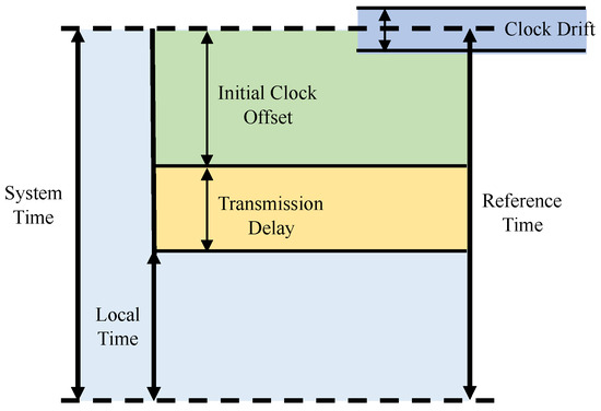
Figure 1.
Clock Error of Reference and Non-Reference Slaves.
When the data frame returns after passing through all the slaves, the local clock time at slave i upon arrival is , and the time when it reaches the reference clock slave is . The transmission delay from slave i to the reference clock slave can be obtained by the following equation:
During system operation, factors such as the use of different crystal oscillators in the reference clock and other slave clocks cause drift in their timing cycles, leading to asynchronous clock operation. This phenomenon, known as clock drift, results in the misalignment of the slave clocks [29].
When the EtherCAT master calculates clock drift, it sends ARMW or FRMW command data frames to each slave [30]. The slaves return their system time and transmission delay to the master [31]. The master can obtain the clock drift either by reading the slave registers or by using the clock drift formula. The formula for calculating the clock drift is as follows:
The existing clock rate adjustment method (ACR) regulates the speed of the slave’s local clock by adjusting the ESC (EtherCAT Slave Controller) based on the sign of , determining whether it is positive or negative [32,33]. When = 0, the local time increases by 10 units every 10 ns. When is positive, it indicates that the local clock speed is greater than the reference clock speed and needs to be decreased, causing the local time to increase by 9 units every 10 ns. When is negative, it indicates that the local clock speed is slower than the reference clock speed and needs to be increased, so the local time increases by 11 units every 10 ns [34].
This method has two main shortcomings. First, it does not consider the transmission delay between the master and the reference slave. Instead, this delay is attributed to the clock offset among the master and the non-reference slaves, leading to an overestimation of the clock offset for these slaves [12]. Consequently, the calculated clock drift is also overestimated. Second, clock drift compensation is only performed based on the sign (positive or negative) of the clock drift [15]. Even with real-time compensation data frames sent to the slaves, significant clock drift still persists. It is essential to compensate for the transmission delay between the master and the reference slave, as well as to consider both the magnitude and sign of the clock drift to maximize the effectiveness of the compensation, thereby reducing the clock drift for each slave.
3. Improved EtherCAT Synchronization Method
3.1. Clock Drift Compensation
To achieve more precise compensation for clock drift errors, the exponential smoothing forecasting method can be applied to estimate the clock drift among slaves. Based on this estimation, the clock offset can be adjusted, effectively reducing clock drift errors.
It should be noted that the main robustness of the proposed method to these phenomena of temperature variation or oscillator aging stems from its core design as a closed-loop, model-independent compensator. Because the algorithm continuously estimates and corrects for instantaneous clock drift (the derivative of the phase error) in real time, it inherently compensates for the net effect of any underlying cause of coherence drift, whether it be temperature change or oscillator aging.
3.1.1. Exponential Smoothing Forecasting
The exponential smoothing method is a time series forecasting method developed from the moving average method. Based on the number of smoothing iterations, the exponential smoothing method can be categorized into Exponential Moving Average (EMA), Double Exponential Smoothing (DES), and Triple Exponential Smoothing (TES). The Exponential Moving Average is suitable for forecasting data without significant trends or seasonal patterns. The Double Exponential Smoothing incorporates a trend component into the EMA, making it ideal for data with pronounced trend changes [14]. The Triple Exponential Smoothing (TES) extends the Exponential Moving Average (EMA) by incorporating both trend and seasonal components, making it well-suited for data with pronounced trends and seasonal variations.
In the absence of an EtherCAT slave synchronization mechanism, synchronization errors will gradually increase without compensation, exhibiting a clear upward trend [35], and no seasonal variations. Therefore, DES is chosen from the exponential smoothing methods.
3.1.2. Improved Clock Drift Compensation Method
The following are the steps for calculating the compensated clock drift:
Initialization:
level: , trend: . Here, is the clock drift value calculated during the first iteration using the clock drift formula, and is the value calculated during the second iteration.
Forecasting, level update:
Trend update:
Compensated clock drift:
where is the level at the k-th iteration, is the trend at the k-th iteration, is the clock drift compensation for slave i at the k-th iteration, and and are the attenuation factors, with values ranging from 0 to 1.
After obtaining the compensated clock drift, subtract it from the clock offset to obtain the new clock offset . Finally, write the to the slave register for compensation.
3.2. Transmission Delay
When calculating the transmission delay between slaves, the ESC chip in EtherCAT slave devices adheres to the “0-3-1-2” port sequence for network transmission [36], as illustrated in Figure 2. Furthermore, the chip records only the timestamp corresponding to the reception of a data frame at each port. Therefore, determining the transmission delay of a slave involves utilizing the port latch times and the specified port sequence.
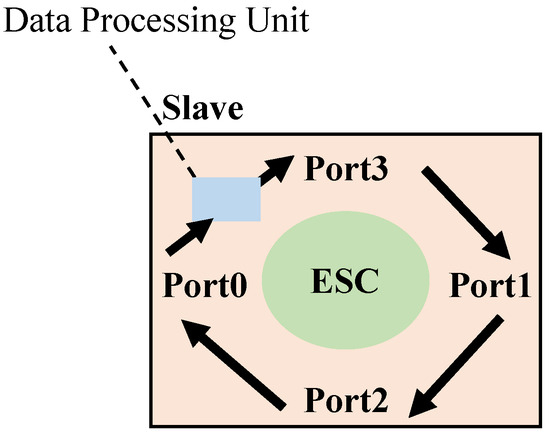
Figure 2.
EtherCAT Slave Chip Port Transmission Sequence.
In the clock synchronization initialization phase, the master sends a data frame and records the number of slaves, the port of each slave that first receives the data frame, and the active ports of the slaves. Based on the number of connected slaves and the port transmission sequence of the slave chips, the master determines the parent slave and the parent port for each slave.
The transmission delay in the EtherCAT master–slave system primarily comprises the delay between the master station and the reference slave station, as well as the delay between non-reference slaves and the reference slave station.
3.2.1. Transmission Delay Between the Master and the Reference Slave
As shown in Figure 3, the transmission delay between the master and the reference slave is calculated by first recording the time when the master sends and receives the data frame, as well as the times when the reference slave receives the data frame at ports 0 and 1. The transmission delay between the master and the reference slave is calculated using Equation (9) as follows [12]:
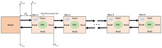
Figure 3.
Master–slave Linear Topology Structure.
In the formula, represents the time when the master sends the data frame, represents the time when the master receives the returned data frame, represents the time when the data frame arrives at port 0 of the reference slave, and represents the time when the data frame arrives at port 1 of the reference slave.
Due to the jitter of the master clock, the transmission delays were uncertain and varied. Since the transmission delay exhibited no significant trend or seasonal variation, this study employed the EMA to calculate the compensated transmission delay between the master and the reference slave. The results were then written into the reference slave’s register for compensation. The calculation formula is as follows:
In the formula, represents the compensated transmission delay between the master and the reference slave at the k-th compensation. is the smoothing factor, which ranges from 0 to 1. is the uncompensated transmission delay between the master and the reference slave, and is the transmission delay obtained from the previous compensation.
3.2.2. The Transmission Delay of Non-Reference Slaves
After calculating the transmission delay between the master and the reference slave, it is necessary to further compute the transmission delays between the reference slave and the other non-reference slaves. This involves calculating the time for a data frame to travel from the parent of slave i to the parent port of slave i.
represents the time required for a data frame to travel from the parent of slave i to the parent port of slave i. is the time at which the parent port of slave i receives the data frame, and is the time at which the previous active port of receives the data frame.
If the number of slaves connected to slave i is greater than 1, the transmission time for the subsequent slaves of slave i must be calculated:
represents the transmission time for the subsequent slaves of slave i, is the time at which the first port of slave i receives the data frame, and is the time at which the previous active port of receives the data frame.
The formula used to calculate the transmission delay of slave i is
In the formula, represents the transmission delay of slave i, and represents the transmission delay of the parent slave of slave i.
3.3. Initial Clock Offset
To achieve time synchronization between the master and the slaves, the time of the master clock is typically used as the reference to calibrate the initial clock time of each slave when calculating their initial clock offsets. After the master clock calibrates the clock of the reference slave, the local clock of the reference slave is then used as the reference clock.
3.3.1. Clock Offset Between the Master and the Reference Slave
Due to the clock offset between the master and the reference clock, as well as the transmission delay (with the master clock experiencing jitter, the compensated transmission delay is used), the following equation holds:
Thus, the offset of the reference clock relative to the master clock can be calculated as follows:
3.3.2. Clock Offset of the Non-Reference Slave
When the data frame reaches the data processing unit of slave i, the local clock time of the slave, denoted as , is recorded. The transmission delay from the reference clock slave to slave i is denoted as . The clock offset between the slave and the reference clock can be calculated using the following formula:
3.4. Implementation of Master–Slave Clock Synchronization
In EtherCAT master–slave clock synchronization, synchronization primarily relies on the master’s manipulation of the registers in the slave’s control chip, the ESC. The flow of the master–slave synchronization method is shown in Figure 4.
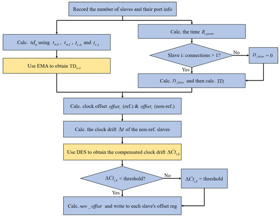
Figure 4.
Master–slave Synchronization Method Flowchart.
First, the master sends a data frame to obtain the number of slaves and port information, followed by determining the topology of the slaves. Using the port information, the master identifies the parent slave and the parent port for each slave. Next, the master records the time of sending and receiving data frames, along with the time when reference slave ports 0 and 1 receive the data frames. The transmission delay between the master and the reference slave is then calculated. This initial transmission delay is recorded in the reference slave’s register. When the EMA is applied for the first time, . Subsequently, the transmission delay of the slave is calculated based on the time for the data frame to leave the parent of the non-reference slave i and return to the parent port, the transmission time of the subsequent slaves, and the transmission delay of the parent slave. Then, the DES algorithm is applied to calculate the compensated clock drift , verify whether it falls below the threshold value (to prevent potential over-compensation), and derive the final compensation value. Finally, the new clock offset is computed by subtracting the compensation value from the clock offset . This new offset is then written to the slave to perform clock error compensation. The compensation function flowchart is shown in Figure 5. This function periodically uses the EMA and DES to compensate for the transmission delay and clock drift between the master and the reference slave, based on the configured cycle. This helps to reduce clock synchronization errors among the slaves and improve synchronization performance.
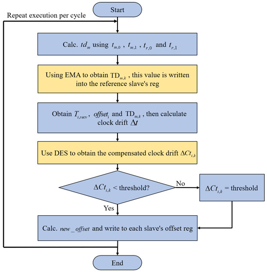
Figure 5.
Compensation Function Flowchart.
4. Synchronization Test
In terms of software, a dual-kernel setup using Linux 4.9.69 and Xenomai 3.0.11 is employed to ensure real-time performance [37]. The open-source master SOME is used as the EtherCAT master [38]. In terms of hardware, the system is based on the Siasun SR4C industrial robot platform. Each Panasonic MINAS A6N servo drive used in this experiment integrates an EtherCAT Slave Controller (ESC) module compliant with the EtherCAT standard. Therefore, these drives function as standard EtherCAT slave devices at the hardware level. Compared with using independent ESC chipset-based boards, employing industrial servo drives provides a more practical validation scenario, as it better reflects real-world applications in multi-axis robotic systems. The controller uses the TL437x-EasyEVM ARM board [39] from Tronlong as the master controller, featuring an AM4379 ARM Cortex-A9 processor. The slaves consist of six Panasonic MINAS A6N series servo drives. The PC communicates with the master controller via a serial port to issue commands and acquire data.
The optimized EtherCAT master–slave synchronization method was applied to modify the open-source master SOME. The test platform, as shown in Figure 6, is a linear topology with one master and six slaves, configured for the EtherCAT master–slave synchronization test.
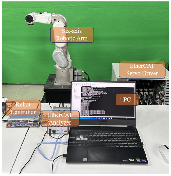
Figure 6.
Experimental Platform.
4.1. Testing Method
The SOME master implements the EtherCAT distributed clock synchronization mechanism, periodically sending synchronization error compensation data frames. During operation, the master sends an FPRD command to read the clock synchronization error from the last slave’s register.
To ensure the accuracy of the experiment, a cold reset is performed before each test to eliminate any influence from previous experiments on the current one.
To visually observe the control effect of synchronization errors after the system stabilizes, synchronization error data is collected every 1 ms. The system waits for the master to enter the operational state, and then 8000 samples are taken after the synchronization error has stabilized. The 8000 sample points are plotted into a histogram using MATLAB R2022b, with a fitted normal distribution curve superimposed. Additionally, the root mean square (RMS) and mean value curves are plotted against the number of samples. The master cycle is set to 1 ms for all experiments.
EtherCAT ensures real-time performance in industrial control through a strict time-deterministic mechanism. Operating on a fixed communication cycle (e.g., 1 ms), its core performance metrics, cycle time and communication jitter, directly dictate the system’s response speed and stability. Utilizing the Distributed Clock mechanism enables nanosecond-level synchronization between master and slave devices, guaranteeing precise timing for message transmission. The real-time communication performance of the master station can be effectively evaluated by measuring the data transmission delay.
To validate the effectiveness of the proposed method, comparative experiments were conducted under identical hardware conditions using the open-source SOME master. Four synchronization methods were tested: clock rate adjustment (ACR), EMA, the proposed DES method, and the improved method. These experiments were conducted in environments with two slaves and six slaves, respectively.
The clock rate adjustment method (ACR) controls the slave’s clock rate by determining the sign of the clock drift. When this method is used to control synchronization error, the resulting clock synchronization error histograms are shown in Figure 7a and Figure 8a.
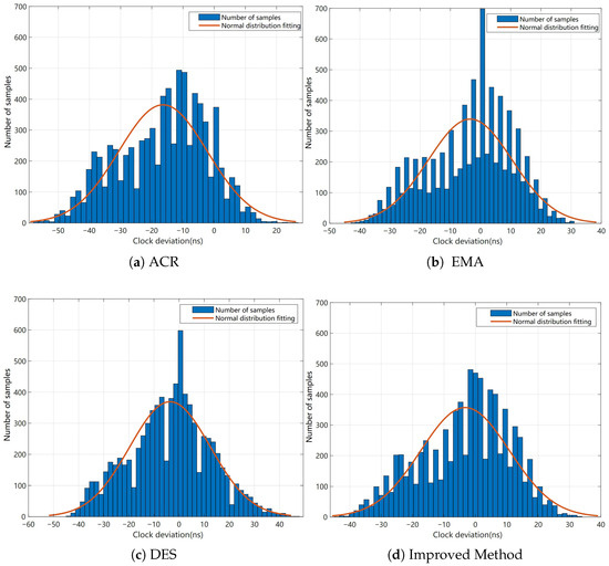
Figure 7.
The synchronization error histogram of each method (2 slaves).
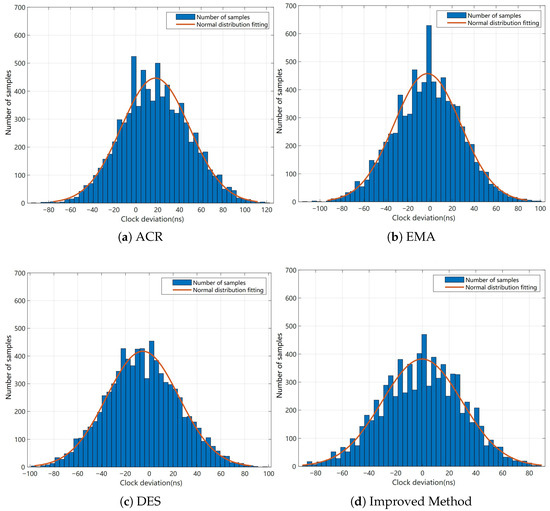
Figure 8.
The synchronization error histogram of each method (6 slaves).
The method described in Reference [13], which uses only the EMA to compensate for the clock drift of each slave, was implemented. The smoothing factor . The synchronization error histograms obtained using this method are shown in Figure 7b and Figure 8b.
The DES described in Section 3.1 was used to compensate for the clock drift of each slave. During this process, the decay factors and were set to 0.9 and 0.5, respectively, while the threshold is set to 5000 ns. The synchronization error histograms obtained using the DES are shown in Figure 7c and Figure 8c.
Additionally, the proposed improved method combines the EMA to compensate for the transmission delay between the master and the reference slave with the DES to compensate for the clock drift of each slave. In this improved method, the smoothing factor for the EMA is set to , while the decay factors for the DES, and , are set to 0.9 and 0.5, respectively. The synchronization error histograms obtained using the improved method are shown in Figure 7d and Figure 8d.
Figure 9 and Figure 10 show the comparison of the Mean and RMS curves for each method in the 2-slave and 6-slave experimental groups, respectively. The root mean square (RMS) is a key indicator for measuring data dispersion. A smaller RMS value indicates lower data dispersion [40,41].
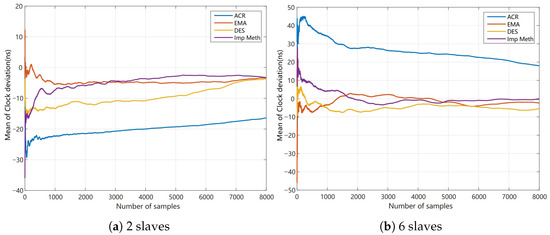
Figure 9.
Comparison of mean curves for each method.
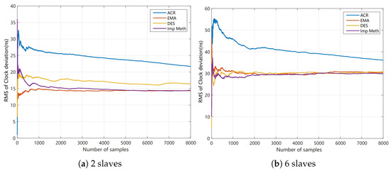
Figure 10.
Comparison of RMS curves for each method.
The synchronization error statistical results for the two-slave and six-slave experimental groups are shown in Table 1 and Table 2.

Table 1.
Synchronization error for 2 slaves.
Table 2.
Synchronization error for 6 slaves.
4.2. Results Analysis
By combining Table 1 with the synchronization error histograms for the two-slave methods, it is evident that the clock rate adjustment method (ACR) in the two-slave experimental group exhibits the largest absolute average synchronization error, while the improved method demonstrates the smallest such error. However, by observing the comparison of the mean value curves for each method in Figure 9a, it can be seen that as the number of sampling points increases, the mean values of the improved method and EMA exhibit greater stability, clearly outperforming the other methods. The comparison of the RMS curves in Figure 10a further confirms this observation. The improved method and EMA have smaller RMS values. In the two-slave group, the RMS value of EMA consistently remains the smallest, indicating that this method exhibits the lowest synchronization error dispersion. Therefore, under the experimental conditions with two slaves, both the improved method and EMA demonstrate advantages in terms of mean value stability and synchronization error dispersion.
Based on Table 2 and the synchronization error histograms for each method in the six-slave group, it is evident that the improved method in the six-slave group exhibits the smallest absolute average synchronization error and the narrowest synchronization error range. The EMA method ranks second in terms of absolute average synchronization error. At the same time, the synchronization error range of DES is relatively small compared to the other methods, except for the improved method. Further analysis of the mean and RMS curves in Figure 9b and Figure 10b reveals that, as the sample size increases, DES exhibits lower synchronization error dispersion. Moreover, the RMS curve of the improved method, which includes transmission delay compensation, remains more stable than the other methods, indicating that the improved method has better robustness. Therefore, in the six-slave experimental scenario, DES also exhibits relatively low synchronization error dispersion. The improved method demonstrates certain advantages in synchronization error control. In addition, preliminary results indicate that the proposed method maintains robust synchronization performance as the number of slaves increases, consistently achieving stable timing accuracy in expanded network configurations. Although the current experiments involve six slaves, the proposed synchronization framework is inherently scalable. When extended to large-scale systems with over 100 synchronized motor drives, the approach can maintain precise timing through distributed delay compensation and DES-based clock drift correction. Each slave can perform local synchronization using DES while remaining globally aligned with the master, ensuring stable performance under higher network loads.
5. Conclusions
This paper conducts an in-depth study and analysis of the distributed clock synchronization principle and synchronization mechanism of the EtherCAT master–slave system, focusing on the shortcomings in synchronization accuracy. Building upon the EMA clock drift compensation method and the master–slave transmission delay compensation method, this paper proposes an improved EtherCAT master–slave synchronization optimization method based on DES. In the initial stage of synchronization, the transmission delay between the master and the reference slave is calculated and written into the register for compensation. During the synchronization process, each non-reference slave experiences clock drift, which is compensated for using the DES. Additionally, due to significant clock jitter at the EtherCAT master during operation, this paper also employs the EMA method to compensate for the transmission delay between the master and the reference slave. Experimental results show that the proposed improved method achieves high synchronization performance in a six-slave experimental scenario. Synchronization errors were controlled within a range of ±90 ns, with the average synchronization error stabilizing around zero. Compared to using only the EMA for clock drift compensation, the proposed method reduced the synchronization error range by approximately 16.36%, significantly improving synchronization accuracy among EtherCAT slaves.
In future work, we plan to significantly enhance the robustness and practical applicability of our delay estimation and compensation framework. Firstly, we will extend our investigation to model and compensate for the combined effects of dynamic network load, data packet loss, and delay jitter, which are critical factors in real-world industrial networks. This will involve conducting comprehensive uncertainty and sensitivity analyses to rigorously quantify the impact of these stochastic factors on synchronization performance. Secondly, to firmly establish the statistical significance of any performance improvements resulting from these advanced models, we will employ rigorous statistical testing methodologies [42,43], including Analysis of Variance (ANOVA) and t-tests, on data from extensive repeated experiments. These steps will provide a more robust validation of our method and strengthen its foundation for industrial deployment. Furthermore, we plan to validate the proposed algorithm in large-scale EtherCAT networks comprising more than 100 synchronized slave nodes to comprehensively evaluate its scalability and robustness under high communication loads. Future research will also focus on integrating adaptive parameter tuning and distributed delay estimation mechanisms to further enhance real-time performance and synchronization stability in complex industrial environments.
Author Contributions
Conceptualization, B.W. and H.W.; Methodology, K.Z. and X.C.; Validation, M.G.; Formal analysis, Y.J.; Writing—original draft, H.W. All authors have read and agreed to the published version of the manuscript.
Funding
This work was funded in part by the Key Research and Development Program of Zhejiang Province, China, No. 2023C03186.
Data Availability Statement
Data are available on request due to restrictions on privacy.
Conflicts of Interest
The authors declare no conflicts of interest.
References
- Diaz, H.; Poór, P. Enhancing Industrial Automation: A Practical Study on Communication Protocols and EdMES Software Integration. IEEE Rev. Iberoam. Tecnol. Aprendiz. 2024, 19, 361–370. [Google Scholar] [CrossRef]
- Delgado, R.; Cho, S.Y.; Choi, B.W. PyIgH: A unified architecture of IgH EtherCAT Master based on Python considering hard real-time constraints. Microprocess. Microsyst. 2024, 109, 105085. [Google Scholar] [CrossRef]
- Orfanus, D.; Indergaard, R.; Prytz, G.; Wien, T. EtherCAT-based platform for distributed control in high-performance industrial applications. In Proceedings of the 2013 IEEE 18th Conference on Emerging Technologies & Factory Automation (ETFA), Cagliari, Italy, 10–13 September 2013; IEEE: Piscataway, NJ, USA, 2013; pp. 1–8. [Google Scholar]
- Mughal, D.M.; Kim, Y.H.; Jeon, B.; Lee, S.; Chung, M.Y. Acyclic Traffic Management in EtherCAT Networks: Novel Adaptive Grouping and Telegram Assignment Mechanism. IEEE Access 2024, 12, 176406–176417. [Google Scholar] [CrossRef]
- Giovinazzo, F.; Perri, A.; Staiano, M.; Grella, F.; Sartore, M.; Adami, M.; Galletti, R.; Cannata, G. Design, Implementation and Testing of an EtherCAT-based Network for Multi-modal Distributed Sensing Architectures. In Proceedings of the 2024 IEEE 20th International Conference on Automation Science and Engineering (CASE), Bari, Italy, 28 August–1 September 2024; pp. 830–837. [Google Scholar]
- Yoo, T.; Choi, B.W. Real-Time Performance Benchmarking of RISC-V Architecture: Implementation and Verification on an EtherCAT-Based Robotic Control System. Electronics 2024, 13, 733. [Google Scholar] [CrossRef]
- Cereia, M.; Bertolotti, I.C.; Scanzio, S. Performance of a real-time EtherCAT master under Linux. IEEE Trans. Ind. Inf. 2011, 7, 679–687. [Google Scholar] [CrossRef]
- Nguyen, H.; Nguyen, T.P.; Ngo, H.Q.T. Using EtherCAT technology to launch online automated guided vehicle manipulation with unity-based platform for smart warehouse management. IET Control Theory Appl. 2024, 18, 229–243. [Google Scholar] [CrossRef]
- Paprocki, M.; Erwiński, K. Synchronization of electrical drives via EtherCAT fieldbus communication modules. Energies 2022, 15, 604. [Google Scholar] [CrossRef]
- Ahn, J.; Park, S.; Sim, J.; Park, J. Dual-channel EtherCAT control system for 33-DOF humanoid robot TOCABI. IEEE Access 2023, 11, 44278–44286. [Google Scholar] [CrossRef]
- Zhang, J.; Xia, M.; Li, H.; Li, S.; Shi, J. The Design and Real-Time Optimization of an EtherCAT Master for Multi-Axis Motion Control. Electronics 2024, 13, 3101. [Google Scholar] [CrossRef]
- Feng, R.; Yasuo, S. Research and optimization of EtherCAT distributed clock synchronization algorithm. Instrum. Tech. Sens. 2022, 10, 113–118. (In Chinese) [Google Scholar]
- Park, S.M.; Kim, H.; Kim, H.W.; Cho, C.N.; Choi, J.Y. Synchronization improvement of distributed clocks in EtherCAT networks. IEEE Commun. Lett. 2017, 21, 1277–1280. [Google Scholar] [CrossRef]
- Sun, J.; Chen, P.; Luo, Y. A Fractional Order Control and Correction Strategy for EtherCAT Communication Clock Drift. In Proceedings of the 17th International Design Engineering Technical Conferences and Computers and Information in Engineering Conference, Virtual, 17–19 August 2021; American Society of Mechanical Engineers: New York, NY, USA, 2021; Volume 85437, p. V007T07A023. [Google Scholar]
- Park, S.M.; Kim, H.W.; Kim, H.J.; Choi, J.Y. Accuracy improvement of master–slave synchronization in EtherCAT networks. IEEE Access 2020, 8, 58620–58628. [Google Scholar] [CrossRef]
- Ganz, D.; Leschke, S.; Doran, H.D. Improving EtherCAT master-slave synchronization precision using PTCP embedded in EtherCAT frames: A proof-of-concept. In Proceedings of the 2015 IEEE World Conference on Factory Communication Systems (WFCS), Palma de Mallorca, Spain, 27–29 May 2015; IEEE: Piscataway, NJ, USA, 2015; pp. 1–7. [Google Scholar]
- Choi, B.J.; Liang, H.; Shen, X.; Zhuang, W. DCS: Distributed asynchronous clock synchronization in delay tolerant networks. IEEE Trans. Parallel Distrib. Syst. 2011, 23, 491–504. [Google Scholar] [CrossRef]
- Exel, R.; Bigler, T.; Sauter, T. Asymmetry mitigation in IEEE 802.3 Ethernet for high-accuracy clock synchronization. IEEE Trans. Instrum. Meas. 2013, 63, 729–736. [Google Scholar] [CrossRef]
- Ghandour, M.; Jleilaty, S.; Ait Oufroukh, N.; Olaru, S.; Alfayad, S. Real-Time EtherCAT-Based Control Architecture for Electro-Hydraulic Humanoid. Mathematics 2024, 12, 1405. [Google Scholar] [CrossRef]
- Cui, J.; Du, Z.; Chen, N.; Liu, Q.; Xu, H.; Liu, Y.; An, H.; Li, H. Real-time multiaxis motion control based on EtherCAT protocol. In Proceedings of the Fifth International Conference on Computer Vision and Data Mining (ICCVDM 2024), Changchun, China, 19–21 July 2024; SPIE: Bellingham, WA, USA, 2024; Volume 13272, pp. 561–566. [Google Scholar]
- Cena, G.; Bertolotti, I.C.; Scanzio, S.; Valenzano, A.; Zunino, C. Evaluation of EtherCAT distributed clock performance. IEEE Trans. Ind. Inf. 2011, 8, 20–29. [Google Scholar] [CrossRef]
- Ghandour, M.; Ait-Oufroukh, N.; Alfayad, S. Control Architecture for Humanoid with Real-Time Electro-Hydraulic Actuator. In Proceedings of the 2024 International Conference on Networking, Sensing and Control (ICNSC), Hangzhou, China, 18–20 October 2024; IEEE: Piscataway, NJ, USA, 2024; pp. 1–6. [Google Scholar]
- Yoo, T.; Choi, B.W. Interactive Path Editing and Simulation System for Motion Planning and Control of a Collaborative Robot. Electronics 2024, 13, 2857. [Google Scholar] [CrossRef]
- Meng, X.; Wang, Y.; Yin, X.; Fu, H.; Sun, S.; Sun, Y. Investigation of Force-Controlled Polishing of Complex Curved PMMA Parts on a Machining Center. Machines 2024, 12, 259. [Google Scholar] [CrossRef]
- Park, S.M.; Kwon, Y.; Choi, J.Y. Time synchronization between EtherCAT network and external processor. IEEE Commun. Lett. 2020, 25, 103–107. [Google Scholar] [CrossRef]
- Stój, J. Cost-effective hot-standby redundancy with synchronization using EtherCAT and real-time ethernet protocols. IEEE Trans. Autom. Sci. Eng. 2020, 18, 2035–2047. [Google Scholar] [CrossRef]
- Smołka, I.; Stój, J. Utilization of SDN technology for flexible EtherCAT networks applications. Sensors 2022, 22, 1944. [Google Scholar] [CrossRef]
- Libo, C.; Taiyong, W.; Songhui, J.; Chong, T.; Ying, T. Innovation of EtherCAT adaptive synchronization control in embedded CNC. Int. J. Commun. Syst. 2023, 36, e5462. [Google Scholar] [CrossRef]
- Chen, X.; Li, D.; Wan, J.; Zhou, N. A clock synchronization method for EtherCAT master. Microprocess. Microsyst. 2016, 46, 211–218. [Google Scholar] [CrossRef]
- Ma, Z.; Li, Z.; Tian, Y.; Tong, W. EtherCAT protocol field segmentation and correlation analysis. In Proceedings of the Third International Conference on Computer Communication and Network Security (CCNS 2022), Hohhot, China, 15–17 July 2022; SPIE: Bellingham, WA, USA, 2022; Volume 12453, pp. 288–293. [Google Scholar]
- Fey, J.H.; Hinrichsen, F.; Mallwitz, R. Real-Time control of a Modular Multilevel Converter via MATLAB/Simulink and EtherCAT fieldbus. In Proceedings of the 2022 IEEE 13th International Symposium on Power Electronics for Distributed Generation Systems (PEDG), Kiel, Germany, 26–29 June 2022; pp. 1–5. [Google Scholar]
- Wang, H.; Wang, C.; Xu, W. Low-cache high-deterministic mesochronous dual-clock FIFO buffer. IEICE Electron. Express 2024, 21, 20240555. [Google Scholar] [CrossRef]
- Xu, J.; Fang, L.; Zhao, Q.; Wan, Y.; Gao, Y.; Wang, H. Clock Drift Compensation for Master-Slave Clock Synchronization in EtherCAT Networks. IEICE Trans. Fundam. Electron. Commun. Comput. Sci. 2024, E108–A, 566–570. [Google Scholar]
- Liu, J.; Yang, L.; Xu, D.; Wu, X. A high precision clock synchronization algorithm for the EtherCAT. In Proceedings of the 2017 12th IEEE Conference on Industrial Electronics and Applications (ICIEA), Siem Reap, Cambodia, 18–20 June 2017; IEEE: Piscataway, NJ, USA, 2017; pp. 1369–1374. [Google Scholar]
- Nazim, A.; Afthanorhan, A. A comparison between single exponential smoothing (SES), double exponential smoothing (DES), holt’s (brown) and adaptive response rate exponential smoothing (ARRES) techniques in forecasting Malaysia population. Glob. J. Math. Anal. 2014, 2, 276–280. [Google Scholar]
- Xing, H.; Jia, H.; Yanqianga, L. Motion control system using sercos over ethercat. Procedia Eng. 2011, 24, 749–753. [Google Scholar] [CrossRef][Green Version]
- Moon, Y.S.; Ko, N.Y.; Lee, K.S.; Bae, Y.C.; Park, J.K. Real-time EtherCAT master implementation on Xenomai for a robot system. Int. J. Fuzzy Log. Intell. Syst. 2009, 9, 244–248. [Google Scholar] [CrossRef][Green Version]
- Ruo Roch, M.; Martina, M. A Low Cost Open Platform for Development and Performance Evaluation of IoT and IIoT Systems. In Proceedings of the International Conference on Applications in Electronics Pervading Industry, Environment and Society (ApplePies 2023), Genoa, Italy, 27–29 September 2023; Spring: Cham, Switzerland, 2023; pp. 155–161. [Google Scholar][Green Version]
- Bui, T.T.; Ngo, H.Q.T. Emerging the real-time performance for the single axis slave controller in the decentralised network. IET Collab. Intell. Manuf. 2023, 5, e12086. [Google Scholar] [CrossRef]
- Zhang, B.; Sennrich, R. Root mean square layer normalization. Adv. Neural Inf. Process. Syst. 2019, 32, 12360–12371. [Google Scholar]
- Hespanha, J.P. Root-mean-square gains of switched linear systems. IEEE Trans. Autom. Control 2003, 48, 2040–2045. [Google Scholar] [CrossRef]
- Basar, G.; Der, O.; Guvenc, M.A. AI-powered hybrid metaheuristic optimization for predicting surface roughness and kerf width in CO2 laser cutting of 3D-printed PLA-CF composites. J. Thermoplast. Compos. Mater. 2025, 38, 08927057251344183. [Google Scholar] [CrossRef]
- Ürgün, S.; Yiğit, H.; Fidan, S.; Sınmazçelik, T. Optimization of laser cutting parameters for PMMA using metaheuristic algorithms. Arab. J. Sci. Eng. 2024, 49, 12333–12355. [Google Scholar] [CrossRef]
Disclaimer/Publisher’s Note: The statements, opinions and data contained in all publications are solely those of the individual author(s) and contributor(s) and not of MDPI and/or the editor(s). MDPI and/or the editor(s) disclaim responsibility for any injury to people or property resulting from any ideas, methods, instructions or products referred to in the content. |
© 2025 by the authors. Licensee MDPI, Basel, Switzerland. This article is an open access article distributed under the terms and conditions of the Creative Commons Attribution (CC BY) license (https://creativecommons.org/licenses/by/4.0/).