Intelligent ANN-Based Controller for Decentralized Power Grids’ Load Frequency Control
Abstract
1. Introduction
1.1. General Background
1.2. Literature Review
1.3. Motivation and Research Gap
1.4. Contributions
- The proposed method enhances frequency stability under the intermittent and stochastic behavior of Renewable Energy Sources (RESs), such as wind and solar, which lack inherent inertia.
- By incorporating the Inertia Emulation Technique (IET) within the HVDC tie-line framework, the study offers a practical pathway to synthetic inertia integration, a crucial requirement in low-inertia renewable power systems.
- The intelligent ANN structure enables adaptive self-tuning of controller parameters, reducing reliance on manual retuning and improving autonomy and resilience in large-scale smart grids.
- The multi-area, multi-source configuration (thermal–hydro–gas–RES integrated IEEE-39 bus system) demonstrates the controller’s ability to maintain dynamic stability and power-sharing coordination in decentralized, deregulated energy markets.
1.5. Limitations and Possible Extensions of the Proposed Method
1.6. Paper Organization
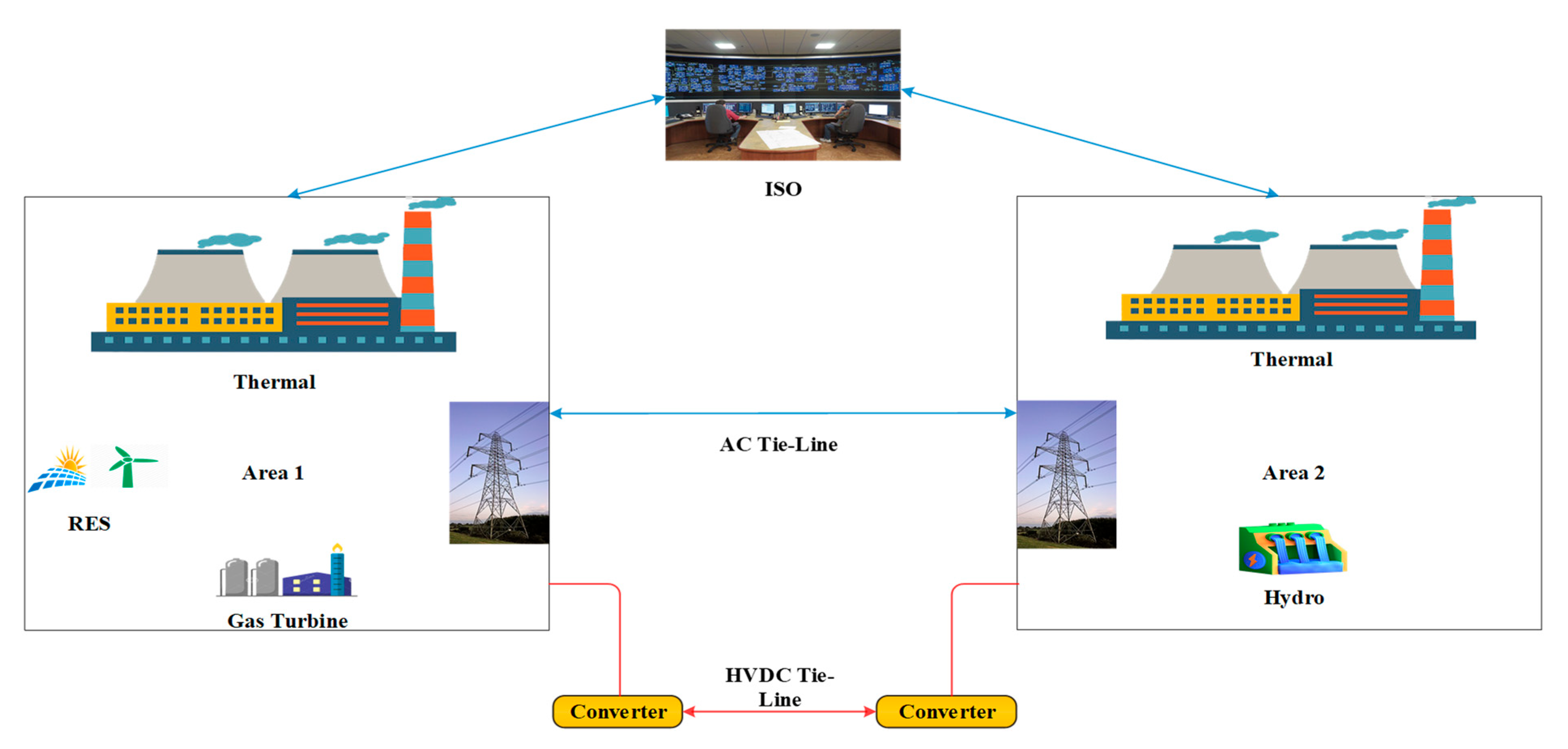
2. Examined System
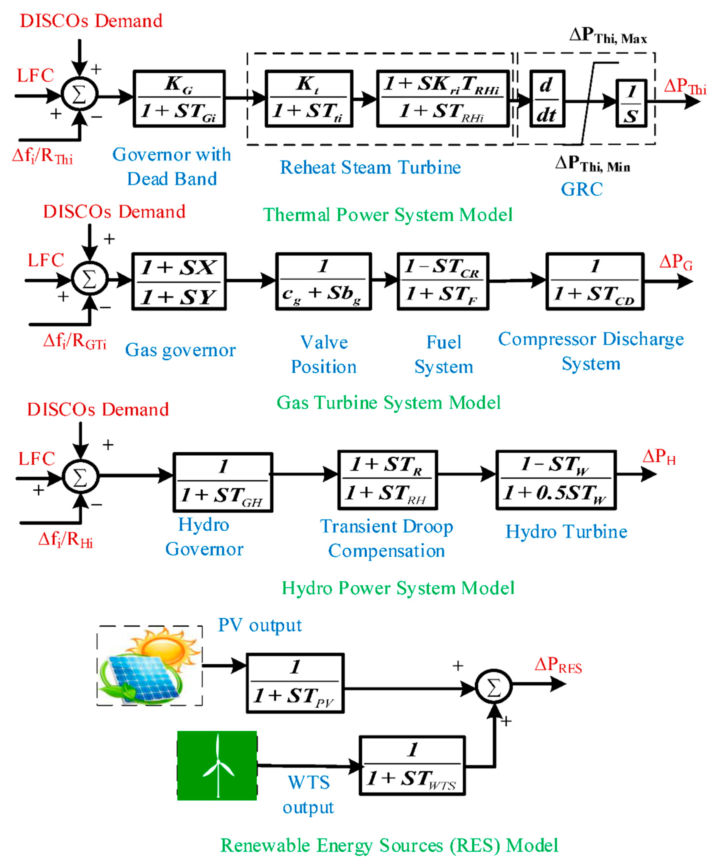
2.1. Experimental System Modeling
2.2. Performance Index as Well as Objective Function
3. IET-Based AC-HVDC Tie-Line Modeling
3.1. Model Investigation of the AC-HVDC Tie-Line Utilizing IET
3.2. Compute the Associated Tie-Line Synchronization Coefficients
3.3. Using HVDC Tie-Lines with the IET
4. Deregulation for Proposed LFC
5. Techniques for Controller and Optimization Proposed
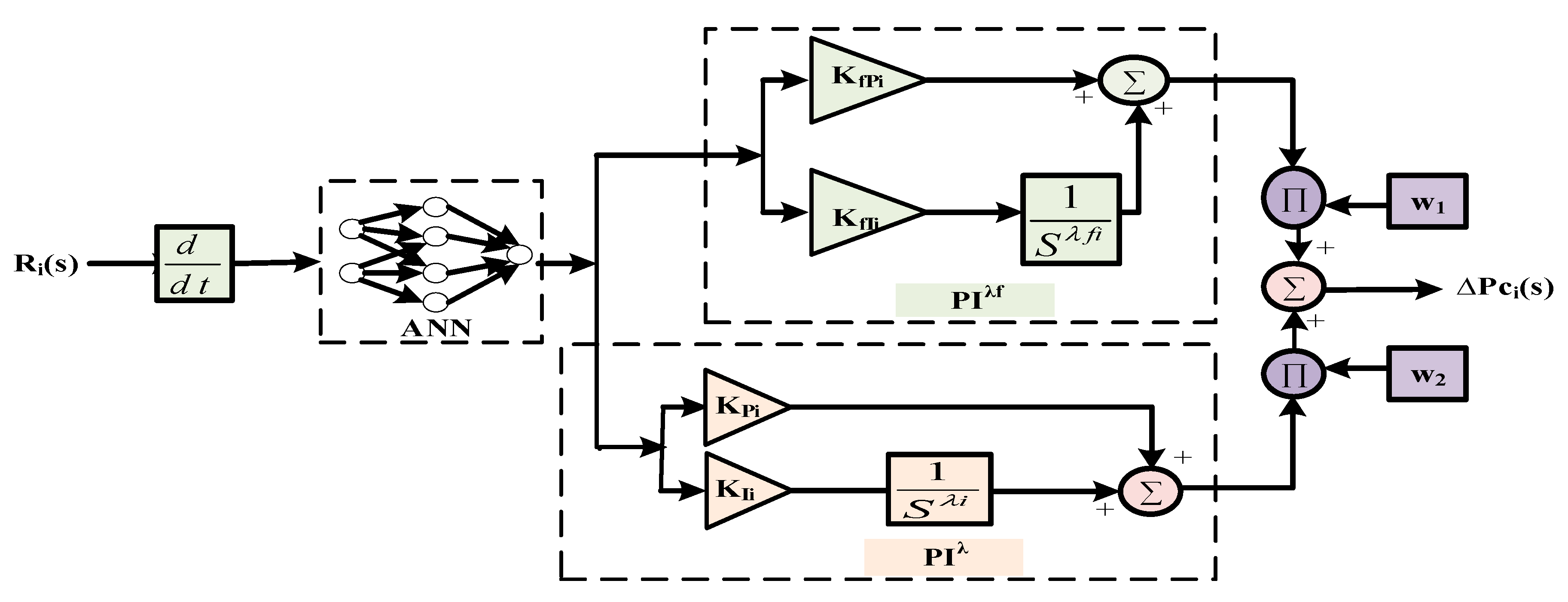
5.1. The (PIλ + PIλf) Controller Based on ANN
5.2. Backpropagation Algorithm
- ⮚
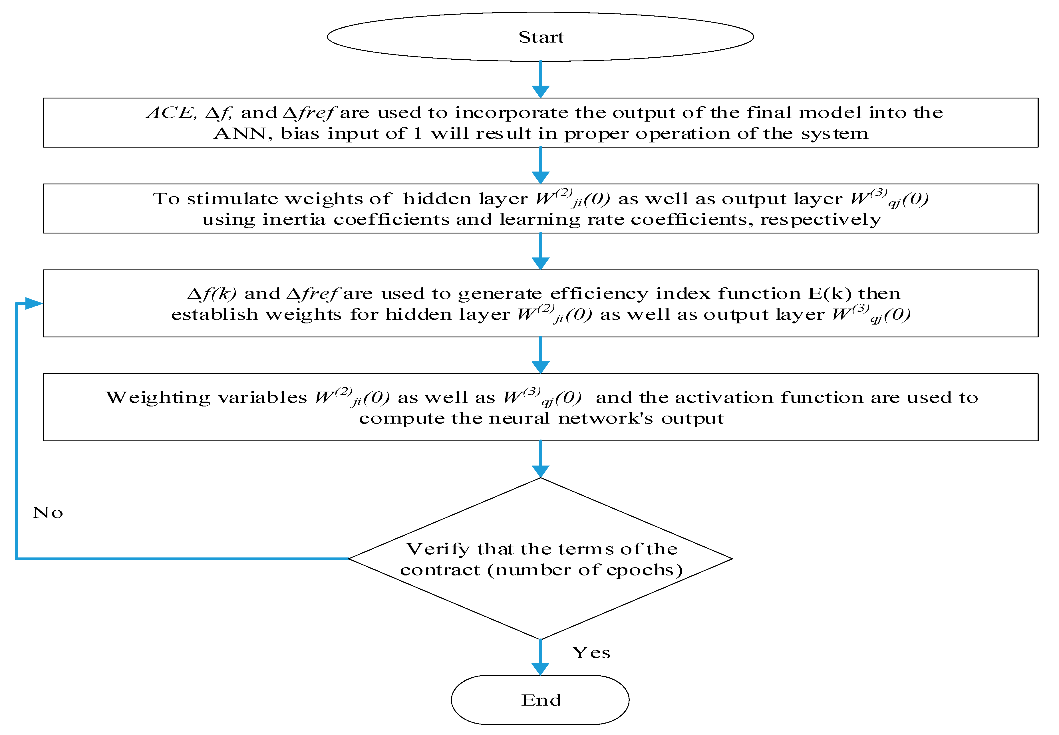
- Step 1: ACE, ∆f, as well as ∆fref are used to incorporate the output of the final model into the ANN (Figure 2). A bias input of 1 will result in the proper operation of the system. It is necessary to initialize the weights of the output layer (W(3)qj(0)) as well as the hidden layer (W(2)ji(0)) using inertia coefficients and learning rate coefficients, respectively.
- ⮚
- Step 2: ∆f(k) and ∆fref are used to generate the efficiency index function E(k). To take into consideration the system’s ∆f, the authors set ∆fref to zero when creating this scenario.
- ⮚
- Step 3: The authors establish the weights for the hidden layer (W(3)qj(0)) as well as the output layer (W(2)ji(0)).
- ⮚
- Step 4: The most recent weighting variables (W(2)ji(k), W(3)qj(k)) and the activation function are used to compute the neural network’s output. With the parameters of a (PIλ + PIλf) controller, the ANN yields the most efficient result.
- ⮚
- Step 5: Whether the contract’s conditions (the number of epochs) have been met is confirmed. If this condition is not satisfied, k = k + 1 will be used in step 2.
5.3. The Suggested Adaptive (PIλ + PIλf) Controller
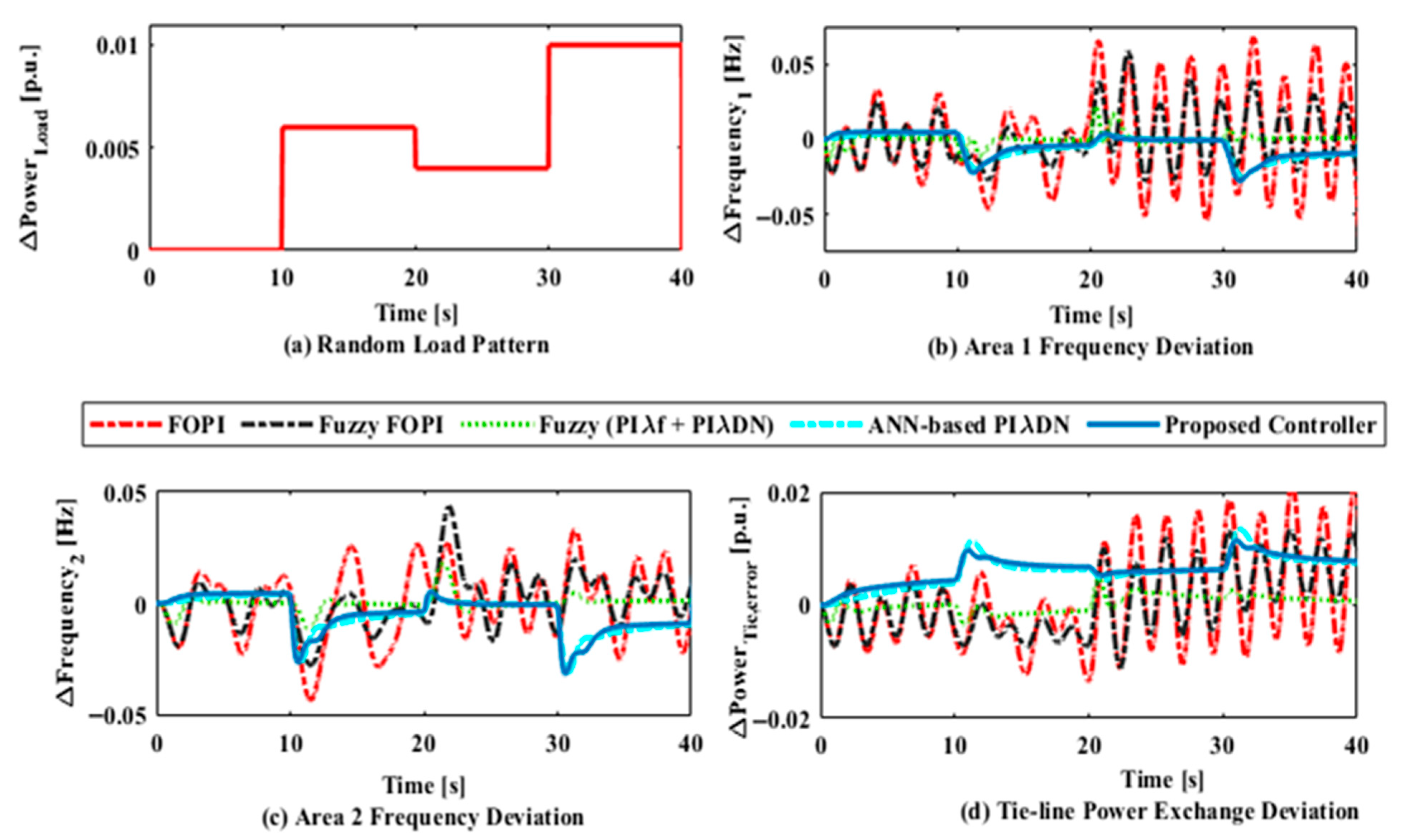
- The controller has been tested under various deregulated scenarios—Poolco-Based (PBT), Bilateral-Based (BBT), and Contract Violation-based (CVT)—each introducing unpredictable load changes and renewable energy fluctuations.
- The system consistently maintained frequency stability, minimal overshoot, and fast settling time, indicating strong resilience to parameter uncertainties and load variations that mimic real-world behavior.
- In practice, Renewable Energy Sources (RESs) like solar and wind exhibit intermittent and unpredictable outputs. The study incorporated this uncertainty (fluctuating between 0.005 p.u. and 0.003 p.u.), and the controller adapted effectively using the ANN’s self-learning and adaptive gain-tuning ability, ensuring frequency restoration even under dynamic renewable penetration levels.
- Unlike conventional PI or PID controllers, which require manual retuning for new operating points, the ANN-based controller automatically updates control parameters through continuous learning. This makes it durable in evolving grid conditions, such as varying generation mixes, grid topology changes, or demand surges.
5.4. Optimization Technique
6. Results and Discussion
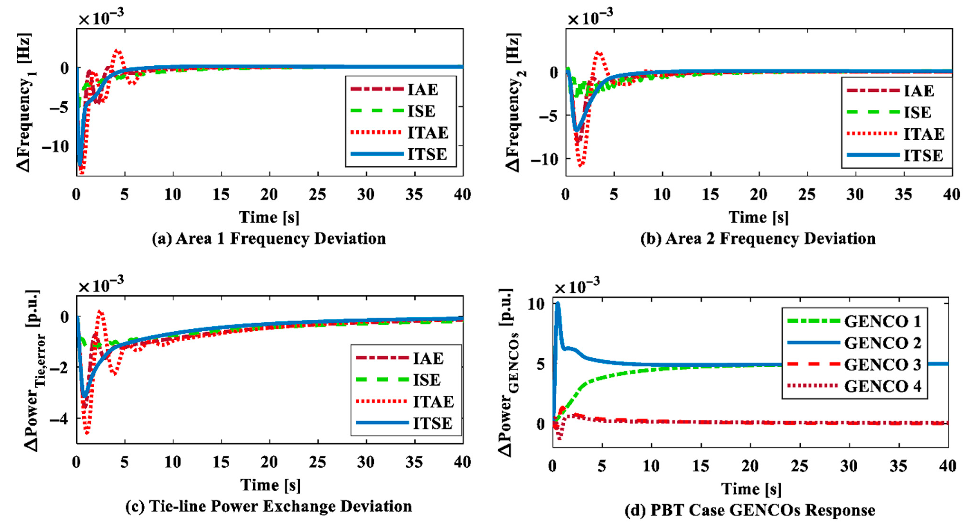
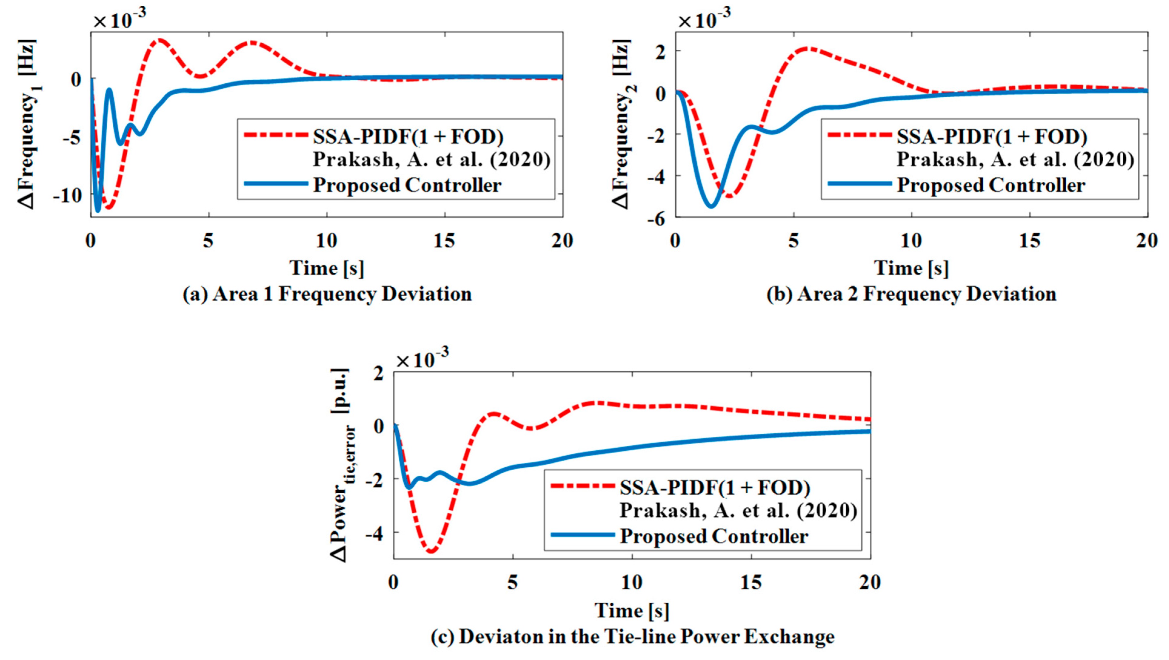
6.1. Case Study 1: Justification for the Suggested Controller
| Controllers | ∆f1 | ∆f2 | ∆P12 | OF | |||||||
|---|---|---|---|---|---|---|---|---|---|---|---|
| OS | US(−ve) | TS | OS | US(-ve) | TS | OS | US(−ve) | TS | |||
| FOPI | 0.057 | 0.055 | 99.5 | 0.028 | 0.0284 | 99.59 | 0.013 | 0.01281 | 99.97 | 4.51 | |
| Fuzzy FOPI | 0.026 | 0.028 | 99.7 | 0.009 | 0.0201 | 99.98 | 0.005 | 0.00882 | 99.92 | 1.13 | |
| Fuzzy (PIλ + PIλDN) | 0.005 | 0.015 | 6.08 | 0.003 | 0.0096 | 6.360 | 0.000 | 0.00319 | 6.801 | 9.52 × 10⁻⁵ | |
| ANN-based PIλDN | 0.001 | 0.012 | 18.1 | 0.025 | 0.0068 | 11.20 | 0.000 | 0.00322 | 97.02 | 6.47 × 10⁻² | |
| Proposed controller | IAE | 0.001 | 0.013 | 16.1 | 0.001 | 0.0088 | 18.01 | 0.000 | 0.00375 | 38.94 | 7.18 × 10⁻² |
| ISE | 0.001 | 0.007 | 22.2 | 0.000 | 0.0034 | 19.01 | 0.000 | 0.00145 | 37.90 | 6.22 × 10⁻² | |
| ITAE | 0.039 | 0.015 | 12.1 | 0.040 | 0.011 | 17.02 | 0.039 | 0.04825 | 41.31 | 0.781 | |
| ITSE | 0.000 | 0.012 | 9.01 | 0.000 | 0.0065 | 13.82 | 0.000 | 0.00196 | 32.75 | 7.02 × 10⁻² | |
| Gains | WAO | VPL | QORSA | |||||||||
|---|---|---|---|---|---|---|---|---|---|---|---|---|
| IAE | ISE | ITAE | ITSE | |||||||||
| Area 1 | Area 2 | Area 1 | Area 2 | Area 1 | Area 2 | Area 1 | Area 2 | Area 1 | Area 2 | Area 1 | Area 2 | |
| KPi | 0.38 | 0.58 | 0.75 | 0.801 | 0.542 | 0.451 | 1.464 | 0.48 | 0.502 | 0.661 | 0.321 | 0.381 |
| KIi | 0.73 | 0.86 | 0.73 | 0.802 | 0.085 | 0.687 | 0.038 | 0.62 | 0.025 | 0.090 | 0.110 | 0.043 |
| KfPi | 0.95 | 0.93 | 0.85 | 0.896 | 0.221 | 0.914 | 0.143 | 0.08 | 0.143 | 0.066 | 0.131 | 0.032 |
| KfIi | 0.65 | 0.97 | 0.63 | 0.912 | 0.038 | 0.296 | 0.221 | 0.05 | 0.181 | 0.014 | 0.161 | 0.011 |
| λi | 0.96 | 0.76 | 0.60 | 0.100 | 1.374 | 1.235 | 1.572 | 1.81 | 1.351 | 1.791 | 0.131 | 0.241 |
| λfi | 0.97 | 0.78 | 0.62 | 0.102 | 1.381 | 1.240 | 1.580 | 1.82 | 1.359 | 1.799 | 1.132 | 0.249 |
| w1 | 0.48 | 0.53 | 0.45 | 0.083 | 0.418 | 0.597 | 0.981 | 0.85 | 0.441 | 0.141 | 0.131 | 0.181 |
| w2 | 0.32 | 0.37 | 0.22 | 0.347 | 0.641 | 0.848 | 1.464 | 0.63 | 0.286 | 0.450 | 0.341 | 0.075 |
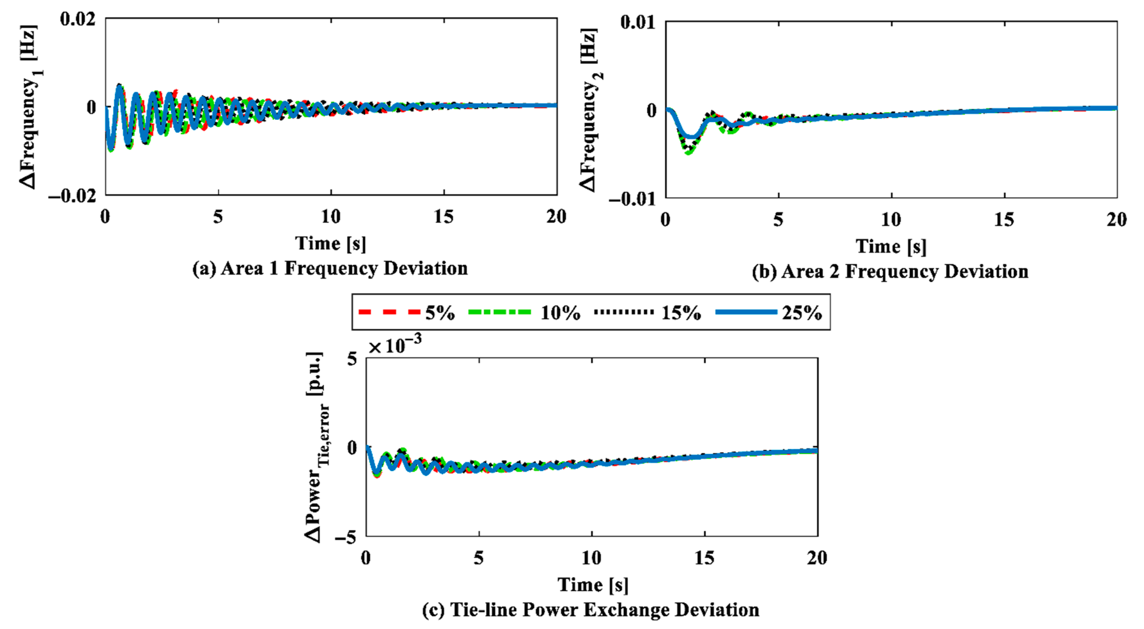
6.2. Case Study 2: Impact of an IET-Based HVDC Tie-Line on Frequency Regulation (BBT), Along with Sensitivity Analysis and Stability Analysis
| Change% in Parameter | +25% of Nominal | −25% of Nominal | |||||
|---|---|---|---|---|---|---|---|
| Parameter | Ts | U.S (−Ve) | O.S. | Ts | U.S (−Ve) | O.S. | |
| TG1 | ∆f1 | 15.2234 | 0.02112 | 0.0000 | 14.2941 | 0.02112 | 0.0000 |
| ∆f2 | 15.1562 | 0.02820 | 0.0000 | 14.7182 | 0.02881 | 0.0000 | |
| ∆Ptie,error | 18.6829 | 0.00000 | 0.0282 | 18.6829 | 0.00000 | 0.0281 | |
| TG2 | ∆f1 | 15.3190 | 0.02104 | 0.0000 | 14.1192 | 0.02103 | 0.0000 |
| ∆f2 | 15.4185 | 0.02892 | 0.0000 | 14.3409 | 0.02889 | 0.0000 | |
| ∆Ptie,error | 18.8957 | 0.00000 | 0.0282 | 18.8912 | 0.00000 | 0.0282 | |
| Tt | ∆f1 | 15.9120 | 0.02103 | 0.0000 | 14.4571 | 0.02103 | 0.0000 |
| ∆f2 | 15.6206 | 0.02785 | 0.0000 | 14.3690 | 0.02869 | 0.0000 | |
| ∆Ptie,error | 18.7647 | 0.00000 | 0.0282 | 18.8734 | 0.00000 | 0.0281 | |
| TRH | ∆f1 | 15.5729 | 0.01957 | 0.0000 | 14.6724 | 0.01942 | 0.0000 |
| ∆f2 | 15.3482 | 0.02830 | 0.0000 | 14.3782 | 0.02829 | 0.0000 | |
| ∆Ptie,error | 18.6492 | 0.00000 | 0.0282 | 18.6825 | 0.00000 | 0.0283 | |
| KPS1 | ∆f1 | 15.6437 | 0.02118 | 0.0000 | 14.8252 | 0.02118 | 0.0000 |
| ∆f2 | 15.2881 | 0.02941 | 0.0000 | 14.9432 | 0.02899 | 0.0000 | |
| ∆Ptie,error | 18.7690 | 0.00000 | 0.0283 | 18.4622 | 0.00000 | 0.0282 | |
| TPS1 | ∆f1 | 15.5720 | 0.02135 | 0.0000 | 14.7823 | 0.02092 | 0.0000 |
| ∆f2 | 15.6843 | 0.02884 | 0.0000 | 14.4689 | 0.02889 | 0.0000 | |
| ∆Ptie,error | 18.9170 | 0.00000 | 0.0283 | 18.9762 | 0.00000 | 0.0282 | |
| KPS2 | ∆f1 | 15.4857 | 0.02179 | 0.0000 | 14.8755 | 0.02182 | 0.0000 |
| ∆f2 | 15.3049 | 0.02966 | 0.0000 | 14.5373 | 0.02987 | 0.0000 | |
| ∆Ptie,error | 18.9786 | 0.00000 | 0.0295 | 18.3284 | 0.00000 | 0.0295 | |
| TPS2 | ∆f1 | 15.6958 | 0.02104 | 0.0000 | 14.9822 | 0.02034 | 0.0000 |
| ∆f2 | 15.8552 | 0.02848 | 0.0000 | 14.2039 | 0.02849 | 0.0000 | |
| ∆Ptie,error | 18.2384 | 0.00000 | 0.0283 | 18.3748 | 0.00000 | 0.0280 | |
| TGH | ∆f1 | 15.2874 | 0.02995 | 0.0000 | 14.8729 | 0.02098 | 0.0000 |
| ∆f2 | 15.3276 | 0.02819 | 0.0000 | 14.1278 | 0.02801 | 0.0000 | |
| ∆Ptie,error | 18.4764 | 0.00000 | 0.0284 | 18.3984 | 0.00000 | 0.0281 | |
| TR | ∆f1 | 15.3746 | 0.02134 | 0.0000 | 14.3948 | 0.02036 | 0.0000 |
| ∆f2 | 15.3981 | 0.02949 | 0.0000 | 14.2837 | 0.02911 | 0.0000 | |
| ∆Ptie,error | 18.7384 | 0.00000 | 0.0286 | 18.4748 | 0.00000 | 0.0281 | |
| cg | ∆f1 | 15.0372 | 0.02148 | 0.0000 | 14.6562 | 0.02177 | 0.0000 |
| ∆f2 | 15.1348 | 0.02832 | 0.0000 | 14.1457 | 0.02826 | 0.0000 | |
| ∆Ptie,error | 18.3394 | 0.00000 | 0.0287 | 18.2376 | 0.00000 | 0.0282 | |
| bg | ∆f1 | 15.3287 | 0.02112 | 0.0000 | 14.0924 | 0.02046 | 0.0000 |
| ∆f2 | 15.3893 | 0.02889 | 0.0000 | 14.1396 | 0.02889 | 0.0000 | |
| ∆Ptie,error | 18.9227 | 0.00000 | 0.0284 | 18.1318 | 0.00000 | 0.0282 | |
| X | ∆f1 | 15.3920 | 0.01962 | 0.0000 | 14.4829 | 0.02057 | 0.0000 |
| ∆f2 | 15.3891 | 0.02892 | 0.0000 | 14.1813 | 0.02861 | 0.0000 | |
| ∆Ptie,error | 18.4734 | 0.00000 | 0.0283 | 18.1570 | 0.00000 | 0.0281 | |
| Y | ∆f1 | 15.4024 | 0.02189 | 0.0000 | 14.5385 | 0.02052 | 0.0000 |
| ∆f2 | 15.3076 | 0.02824 | 0.0000 | 14.2489 | 0.02835 | 0.0000 | |
| ∆Ptie,error | 18.4280 | 0.00000 | 0.0285 | 18.4829 | 0.00000 | 0.0284 | |
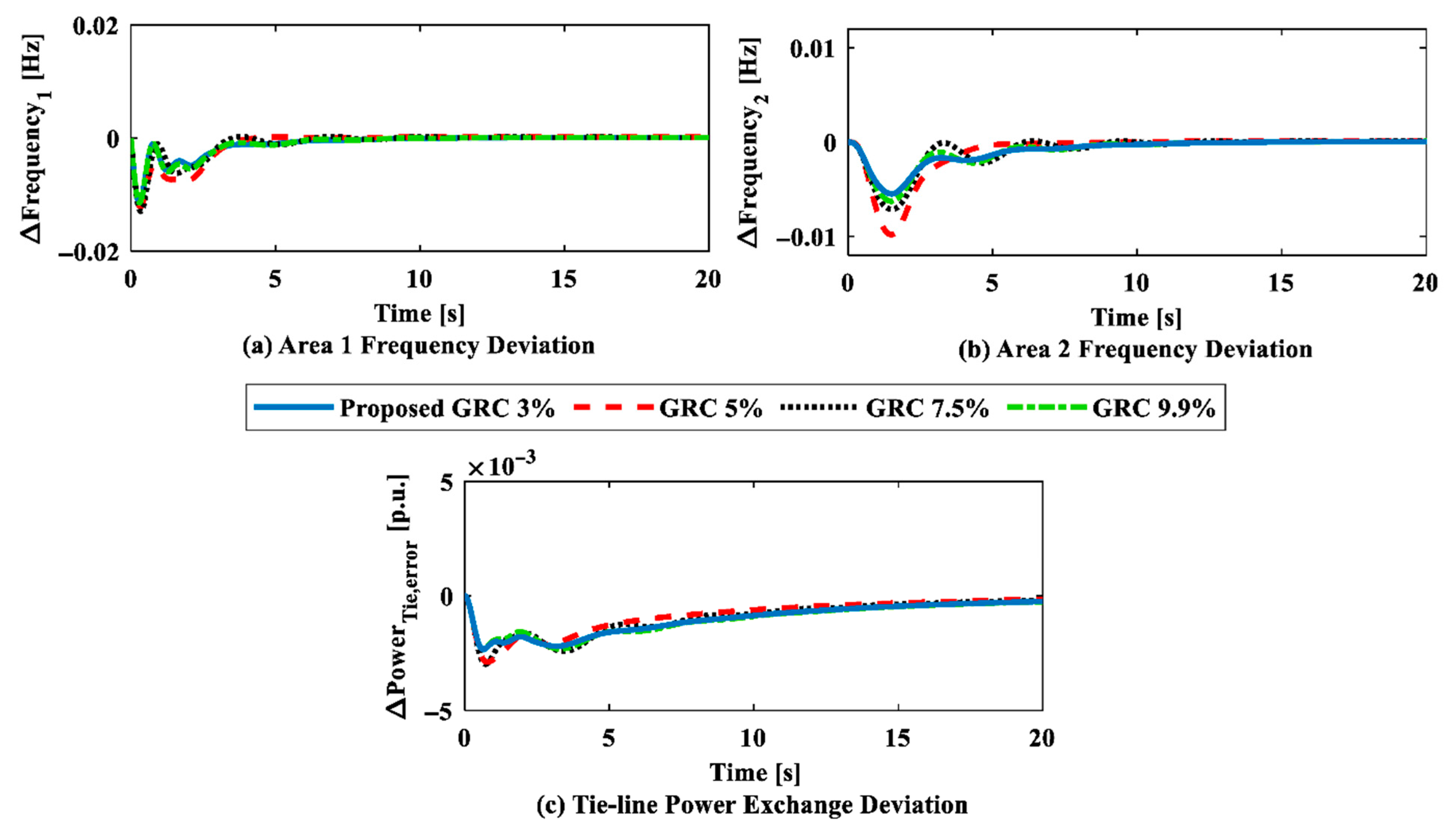
| Control Parameters | Proposed GRC 3% | GRC 5% | GRC 7.5% | GRC 9.9% | ||||
|---|---|---|---|---|---|---|---|---|
| Area 1 | Area 2 | Area 1 | Area 2 | Area 1 | Area 2 | Area 1 | Area 2 | |
| KPi | 0.1307 | 0.0081 | 0.9063 | 0.2015 | 0.0508 | 0.2402 | 0.0941 | 0.4213 |
| KIi | 0.0261 | 0.0111 | 0.2047 | 0.3515 | 0.1860 | 0.3020 | 0.0464 | 0.3337 |
| KfPi | 0.0824 | 0.0179 | 0.2108 | 0.3741 | 0.3290 | 0.0186 | 0.1975 | 0.0820 |
| KfIi | 0.0205 | 0.0014 | 0.0222 | 0.3895 | 0.0132 | 0.0086 | 0.0486 | 0.0030 |
| λi | 0.2914 | 0.0150 | 0.1209 | 0.1764 | 0.0594 | 0.2041 | 0.0252 | 0.2907 |
| λfi | 0.0370 | 0.2901 | 0.1217 | 0.1904 | 0.1430 | 0.1299 | 0.1382 | 0.4655 |
| w1 | 0.1958 | 0.0022 | 0.3113 | 0.2506 | 0.1852 | 0.2540 | 0.4900 | 0.0985 |
| w2 | 0.3147 | 0.2920 | 0.1282 | 0.6165 | 0.0612 | 0.0899 | 0.2860 | 0.1207 |
6.3. Case Study 3: Contract Violation
6.4. Case Study 4: Survey of Relevant Literature
7. Conclusions
- By adopting an IET-based HVDC tie-line, undershoot is reduced by 49.52% and 59.04%, respectively, according to the results.
- With an IET-based HVDC tie-line, overshoot is reduced by 100% in Areas 1 and 2 (frequency in Area 2, i.e., ∆f2, as well as frequency in Area 1, i.e., ∆f1).
- However, the results show that the IET-based HVDC tie-line performs admirably in preserving the power system’s nominal values.
- Lastly, a modified three-area IEEE-39 bus system is used to test the compatibility of the suggested controller, which has been tweaked by QORSA. In the IEEE-39 bus test system, the controller demonstrates effectiveness in handling real-time load variations.
Author Contributions
Funding
Data Availability Statement
Conflicts of Interest
Abbreviations and Symbols
| LFC | Load Frequency Control | λ | Order of an Integrator |
| ANN | Artificial Neural Network | λf | Integrator’s Noninteger Order |
| HVDC | High Voltage Direct Current | ∆PDi | Change in the Load Demand |
| IET | Inertia Emulation Technique | TR & TRH | Transient Droop |
| QORSA | Quasi-Opposition-learning-based Reptile Search Algorithm | KPsi | Power System Gain |
| PI | Proportional–Integral | Tti | Thermal Turbine Constant |
| AGC | Automatic Generation Control | TGi | Thermal Governor Time Constant |
| ISE | Integral Squared Error | Kri | Thermal Reheat Gain Constant |
| IAE | Integral Absolute Error | cg | Parameter of Valve Position |
| ITSE | Integral Time-weighted Squared Error | bg | Constant of the Valve Actuator |
| ITAE | Integral Time-weighted Absolute Error | Tf | Gas Delay of the Gas Turbine System |
| VPL | Volleyball Premier League | X and Y | Lead and Lag Constant of the Gas Turbine Systems’ Governor Model |
| WOA | Whale Optimization Algorithm | TCD | Discharge Delay of the Gas Turbine System |
| DB | Dead Band | TGH | Hydro Governor Time Constant |
| RES | Renewable Energy Source | TW | Water Discharge Parameter |
| ACE | Area Control Error | TPV | Time Constant of PV |
| GRC | Generation Rate Constraint | TWTS | Time Constant of WTS |
| GENCO | Generation Company | RTHi | Reference Signal of the Thermal Power Plant |
| DISCO | Distribution Company | RGTi | Reference Signal of the Gas Power Plant |
| DPM | DISCO Participation Matrix | RHi | Reference Signal of a Hydro Power Plant |
| KP | Proportional Constant | ∆fi | Change in Frequency of the ith Area |
| KI | Integral Constant | ∆PThi | Change in the Power of the Thermal Power Plant |
| cpf | Contract Participation Factor | ∆PRES | Change in the Power of the RES Power Plant |
| ij | Area Number | ∆PH | Change in the Power of the Hydro Power Plant |
Appendix A
References
- Kundur, P.; Balu, N.J.; Lauby, M.G. Power System Stability and Control; McGraw-Hill: New York, NY, USA, 1994; Volume 7. [Google Scholar]
- Kumar, P.; Kothari, D.P. Recent philosophies of automatic generation control strategies in power systems. IEEE Trans. Power Syst. 2005, 20, 346–357. [Google Scholar] [CrossRef]
- Peddakapu, K.; Mohamed, M.R.; Srinivasarao, P.; Veerendra, A.S.; Kishore, D.J.K.; Leung, P.K. Review on automatic generation control strategies for stabilising the frequency deviations in multi-area power system. Int. J. Ambient Energy 2021, 43, 5571–5594. [Google Scholar] [CrossRef]
- Ramesh, M.; Yadav, A.K.; Pathak, P.K. An extensive review on load frequency control of solar-wind based hybrid renewable energy systems. Energy Sources Part A Recovery Util. Environ. Eff. 2021, 47, 8378–8402. [Google Scholar] [CrossRef]
- Pappachen, A.; Fathima, A.P. Critical research areas on load frequency control issues in a deregulated power system: A state-of-the-art-of-review. Renew. Sustain. Energy Rev. 2017, 72, 163–177. [Google Scholar] [CrossRef]
- Aryan, P.; Raja, G.L. Design and Analysis of Novel QOEO Optimized Parallel Fuzzy FOPI-PIDN Controller for Restructured AGC with HVDC and PEV. Iran. J. Sci. Technol. Trans. Electr. Eng. 2022, 46, 565–587. [Google Scholar] [CrossRef]
- Khamies, M.; Magdy, G.; Hussein, M.E.; Banakhr, F.A.; Kamel, S. An Efficient Control Strategy for Enhancing Frequency Stability of Multi-Area Power System Considering High Wind Energy Penetration. IEEE Access 2020, 8, 140062–140078. [Google Scholar] [CrossRef]
- Vidyarthi, P.K.; Kumar, A. A modified tilt controller for AGC in hybrid power system integrating forecasting of renewable energy sources. Optim. Control Appl. Meth 2023, 45, 185–207. [Google Scholar] [CrossRef]
- Guha, D.; Roy, P.; Banerjee, S. Quasi-oppositional backtracking search algorithm to solve load frequency control problem of interconnected power system. Iran. J. Sci. Technol. Trans. Electr. Eng. 2020, 44, 781–804. [Google Scholar] [CrossRef]
- Khamies, M.; Magdy, G.; Ebeed, M.; Kamel, S. A robust PID controller based on linear quadratic gaussian approach for improving frequency stability of power systems considering renewables. ISA Trans. 2021, 117, 118–138. [Google Scholar] [CrossRef]
- Ahmed, M.; Magdy, G.; Khamies, M.; Kamel, S. Modified TID controller for load frequency control of a two-area interconnected diverse-unit power system. Electr. Power Energy Syst. 2022, 135, 107528. [Google Scholar] [CrossRef]
- Arya, Y. A novel CFFOPI-FOPID controller for AGC performance enhancement of single and multi-area electric power systems. ISA Trans. 2020, 100, 126–135. [Google Scholar] [CrossRef] [PubMed]
- Singh, K.; Amir, M.; Arya, Y. Optimal dynamic frequency regulation of renewable energy based hybrid power system utilizing a novel TDF-TIDF controller. Energy Sources Part A Recovery Util. Environ. Eff. 2022, 44, 10733–10754. [Google Scholar] [CrossRef]
- Sekyere, Y.O.M.; Effah, F.B.; Okyere, P.Y. Optimally tuned cascaded FOPI-FOPIDN with improved PSO for load frequency control in interconnected power systems with RES. J. Electr. Syst. Inf. Technol. 2024, 11, 25. [Google Scholar] [CrossRef]
- Patel, N.C.; Sahu, B.K. Design and implementation of a novel FO-hPID-FPID controller for AGC of multiarea interconnected nonlinear thermal power system. Int. Trans. Electr. Energy Syst. 2021, 31, e13078. [Google Scholar] [CrossRef]
- Aryan, P.; Raja, G.L.; Mehta, U.; Chelliah, T.R.; Muduli, U.R. A Resilient Tri-Parametric Fractional Frequency Control for Cybersecurity Threats Amid Latency. IEEE Trans. Ind. Appl. 2025, 61, 5597–5611. [Google Scholar] [CrossRef]
- Chen, L.; Salem, M.; Ben Hamad, K.; Prabaharan, N.; Ueda, S.; Senjyu, T. Design of a Two-Level Controller for Load Frequency Control in the Presence of Wind Farms and Battery Energy Storage System Based on VIC. IEEE Access 2025, 13, 148254–148268. [Google Scholar] [CrossRef]
- Jin, L.; He, Y.; Zhang, C.-K.; Shangguan, X.-C.; Jiang, L.; Wu, M. Robust Delay-Dependent Load Frequency Control of Wind Power System Based on a Novel Reconstructed Model. IEEE Trans. Cybern. 2022, 52, 8. [Google Scholar] [CrossRef]
- Ojha, S.K.; Maddela, C.O. A FOPIDN-(1+PIDN) controller design and optimization for load frequency control system integrated with renewables and electric vehicles. Electr. Eng. 2025, 107, 7617–7643. [Google Scholar] [CrossRef]
- Jawahar, A.; Ramakrishnan, K. Impact of Time Delay Margin on the Stability of Load Frequency Systems with Electric Vehicle Aggregator. Jordan J. Electr. Eng. 2022, 8, 151–164. [Google Scholar] [CrossRef]
- Demilade, D.; Peter, D.; Oluseyi, O. Optimal Under-Frequency Load Curtailment via Continuous Load Control in a Single Area Power System Using Fuzzy Logic, PIDFuzzy and Neuro Fuzzy (ANFIS) Controllers. Jordan J. Electr. Eng. 2018, 4, 208–223. [Google Scholar]
- Anand, A.; Aryan, P.; Kumari, N.; Raja, G.L. Type-2 fuzzy-based branched controller tuned using arithmetic optimizer for load frequency control. Energy Sources Part A Recovery Util. Environ. Eff. 2022, 44, 4575–4596. [Google Scholar] [CrossRef]
- Singh, R.K.; Verma, V. ANN-tuned PIDN controller for LFC with modified HVDC tie-line in deregulated Environment. Int. J. Inf. Technol. 2023, 15, 4193–4210. [Google Scholar] [CrossRef]
- Singh, R.K.; Verma, V. An Intelligence-Based Controller for Improved Frequency Regulation in Deregulated Power Environment. Jordan J. Electr. Eng. (JJEE) 2024, 10, 3. [Google Scholar] [CrossRef]
- Zhang, H.H.; Gong, L.F.; Liu, X.Z.; Xu, Y.X.; Cheng, G.S.; Liu, Y.; Shi, G.M.; Zheng, C.; Han, Y.J. Design of low-SAR and high on-body efficiency tri-band smartwatch antenna utilizing the theory of characteristic modes of composite PEC-lossy dielectric structures. IEEE Trans. Antennas Propag. 2022, 71, 1913–1918. [Google Scholar] [CrossRef]
- Singh, R.; Kumar, R.; Raj, U.; Shankar, R. Robust Load Frequency Control in Cyber-Vulnerable Smart Grids with Renewable Integration. Energies 2025, 18, 2899. [Google Scholar] [CrossRef]
- Kumar, V.; Sharma, S.; Kumar, V.; Dev, A. Optimal voltage and frequency control strategy for renewable-dominated deregulated power network. Sci. Rep. 2025, 15, 398. [Google Scholar] [CrossRef]
- Debnath, M.K.; Agrawal, R.; Tripathy, S.R.; Choudhury, S. Artificial neural network tuned PID controller for LFC investigation including distributed generation. Int. J. Numer. Model. El. 2020, 33, e2740. [Google Scholar] [CrossRef]
- Abualigah, L.; Abd, M.; Sumari, P.; Woo, Z. Reptile Search Algorithm (RSA): A nature-inspired meta-heuristic optimizer. Expert. Syst. Appl. 2022, 191, 116158. [Google Scholar] [CrossRef]
- Prakash, A.; Kumar, K.; Parida, S.K. PIDF (1 + FOD) controller for load frequency control with SSSC and AC–DC tie-line in deregulated environment. IET Gener. Transm. Distrib. 2020, 14, 2751–2762. [Google Scholar] [CrossRef]
- Gheisarnejad, M.; Khooban, M.H. Design an optimal fuzzy fractional proportional integral derivative controller with derivative filter for load frequency control in power systems. Trans. Inst. Measur. Control 2019, 41, 2563–2581. [Google Scholar] [CrossRef]
- Shangguan, X.-C.; He, Y.; Zhang, C.-K.; Jin, L.; Yao, W.; Jiang, L.; Wu, M. Control Performance Standards-Oriented Event-Triggered Load Frequency Control for Power Systems Under Limited Communication Bandwidth. IEEE Trans. Control Syst. Technol. 2022, 30, 860–868. [Google Scholar] [CrossRef]









| Authors | Algorithm | Controller | Deregulation | Nonlinearity | Energy Storage Systems | Generating Units |
|---|---|---|---|---|---|---|
| Arya Y. [12] | ICA | Fuzzy FOPI-FOPDN | No | None | None | Three-area thermal |
| Sekyere Y.O.M. et al. [14] | PSO | FOPI-FOPIDN | No | GDB, GRC | None | Thermal, PV, wind |
| Patel and Sahu [15] | hPSO-MSC algorithm | FO-hPID-Fuzzy PID | No | GRC | None | Three-area thermal |
| Singh R.K. and Verma V. [24] | QOVPL algorithm | ANN-based (PIλf + PIλDN) | Yes | GDB, GRC, BD | IET | Thermal, hydro, gas, RES |
| Singh R. et al. [26] | QOVPL algorithm | Fuzzy-LADRC | No | GRC | EV | RES |
| Proposed Work | QORSA | ANN-based (PIλ + PIλf) | Yes | GRC | IET | Thermal, hydro, gas, RES, IEEE-39 bus system |
| Parameter | Role in ANN Training | Effect on System Performance |
|---|---|---|
| Number of layers (3) | Defines the model’s ability to map nonlinear relationships | More layers → higher learning capacity, but risk of overfitting |
| Learning rate (η) | Controls weight update magnitude | Too low: slow learning; too high: instability |
| Backpropagation | Optimization algorithm | Reduces frequency error and settling time |
| Hidden neurons | Determine feature extraction capability | More neurons improve accuracy but increase computational cost |
| Control Parameters | FOPI | Fuzzy FOPI | Fuzzy (PIλ + PIλDN) | ANN-Based PIλDN | Proposed Controller | |||||
|---|---|---|---|---|---|---|---|---|---|---|
| A1 | A2 | A1 | A2 | A1 | A2 | A1 | A2 | A1 | A2 | |
| KPi | 0.0234 | 0.1847 | 0.1284 | 0.5526 | 1.2568 | 0.5394 | 0.3972 | 0.0749 | 0.1307 | 0.0081 |
| KIi | 0.1237 | 0.5842 | 0.2493 | 0.1102 | 1.4335 | 0.4831 | 0.1864 | 0.1435 | 0.0261 | 0.0111 |
| KDi | - | - | - | - | 1.9104 | 0.9105 | 0.0815 | 0.0047 | - | - |
| KfPi | - | - | - | - | 1.6359 | 1.1047 | - | - | 0.0824 | 0.0179 |
| KfIi | - | - | - | - | 0.8917 | 1.0048 | - | - | 0.0205 | 0.0014 |
| Ni | - | - | - | - | 61.438 | 62.382 | 17.218 | 27.283 | - | - |
| λi | 0.48901 | - | - | - | 1.1891 | 1.1824 | 1.4182 | 1.8327 | 0.2914 | 0.0150 |
| λfi | - | 0.5934 | 1.5226 | 1.4452 | 0.4605 | 1.5627 | - | - | 0.0370 | 0.2901 |
| K1i | - | - | 0.0971 | 0.1724 | 0.8790 | 1.7628 | - | - | - | - |
| K2i | - | - | 0.3875 | 0.0271 | 0.6864 | 0.5435 | - | - | - | - |
| w1 | - | - | - | - | 1.9852 | 0.5789 | 0.0896 | 0.1408 | 0.1958 | 0.0022 |
| w2 | - | - | - | - | 0.8649 | 1.4072 | 0.0182 | 0.1989 | 0.3147 | 0.2920 |
| Control Parameters | Scenario 1 | Scenario 2 | Scenario 3 | Scenario 4 | ||||
|---|---|---|---|---|---|---|---|---|
| Area 1 | Area 2 | Area 1 | Area 2 | Area 1 | Area 2 | Area 1 | Area 2 | |
| KPi | 0.1152 | 0.2441 | 0.2764 | 0.0195 | 0.0690 | 0.2235 | 0.4268 | 0.3817 |
| KIi | 0.0417 | 0.6758 | 0.0052 | 0.1642 | 0.0961 | 0.8452 | 0.0259 | 0.5947 |
| KfPi | 0.8839 | 0.8944 | 0.8179 | 0.8454 | 0.8298 | 0.8123 | 0.8179 | 0.8219 |
| KfIi | 0.7487 | 0.7682 | 0.7431 | 0.7528 | 0.7437 | 0.7546 | 0.8245 | 0.8346 |
| λi | 1.6547 | 1.7891 | 0.9748 | 0.8724 | 1.1219 | 1.4217 | 0.7965 | 0.6645 |
| λfi | 1.6782 | 1.7936 | 0.9812 | 0.8819 | 1.1429 | 1.4481 | 0.8150 | 0.6814 |
| w1 | 0.1854 | 0.2437 | 0.0912 | 0.2939 | 0.4932 | 0.3464 | 0.7916 | 0.8431 |
| w2 | 0.5641 | 0.7145 | 0.1675 | 0.5627 | 0.1452 | 0.1459 | 0.5949 | 0.3319 |
| Performance | Scenario 1 | Scenario 2 | Improvement (%) | Scenario 3 | Scenario 4 | Improvement (%) | |
|---|---|---|---|---|---|---|---|
| OS | ∆f1 | 0.00424 | 0.00000 | 100 | 0.000298 | 0.000261 | 12.41 |
| ∆f2 | 0.00126 | 0.00000 | 100 | 0.000140 | 0.000120 | 14.28 | |
| US (−ve) | ∆f1 | 0.04917 | 0.02014 | 59.04 | 0.019615 | 0.01172 | 40.24 |
| ∆f2 | 0.044281 | 0.02235 | 49.52 | 0.099116 | 0.046018 | 53.40 | |
| Ts | ∆f1 | 9.1633 | 7.4912 | 18.24 | 22.62 | 21.38 | 5.48 |
| ∆f2 | 10.2546 | 8.8520 | 13.67 | 23.68 | 21.33 | 9.92 | |
| OF | 0.02031 | 0.0084 | 58.64 | 0.0033 | 0.0026 | 21.21 | |
| Performance Terms | Reference [30] | Proposed Controller | Improvement (%) | |
|---|---|---|---|---|
| OS | ∆f1 | 0.003266 | 0.0000000 | 100 |
| ∆f2 | 0.002076 | 0.0000000 | 100 | |
| ∆P12 | 0.000821 | 0.0000000 | 100 | |
| US (−Ve) | ∆f1 | 0.011600 | 0.0114429 | 1.35 |
| ∆f2 | 0.004970 | 0.00548245 | −10.31 | |
| ∆P12 | 0.004721 | 0.00233316 | 50.57 | |
| Ts | ∆f1 | 9.0973 | 7.02252 | 22.80 |
| ∆f2 | 16.8061 | 8.51215 | 49.35 | |
| ∆P12 | 19.2226 | 9.43779 | 50.90 | |
| OF | 0.0002435 | 0.0001542 | 36.67 | |
Disclaimer/Publisher’s Note: The statements, opinions and data contained in all publications are solely those of the individual author(s) and contributor(s) and not of MDPI and/or the editor(s). MDPI and/or the editor(s) disclaim responsibility for any injury to people or property resulting from any ideas, methods, instructions or products referred to in the content. |
© 2025 by the authors. Licensee MDPI, Basel, Switzerland. This article is an open access article distributed under the terms and conditions of the Creative Commons Attribution (CC BY) license (https://creativecommons.org/licenses/by/4.0/).
Share and Cite
Singh, R.; Kumar, R.; Shankar, R.; Singh, R.K. Intelligent ANN-Based Controller for Decentralized Power Grids’ Load Frequency Control. Processes 2025, 13, 3562. https://doi.org/10.3390/pr13113562
Singh R, Kumar R, Shankar R, Singh RK. Intelligent ANN-Based Controller for Decentralized Power Grids’ Load Frequency Control. Processes. 2025; 13(11):3562. https://doi.org/10.3390/pr13113562
Chicago/Turabian StyleSingh, Rambaboo, Ramesh Kumar, Ravi Shankar, and Rakesh Kumar Singh. 2025. "Intelligent ANN-Based Controller for Decentralized Power Grids’ Load Frequency Control" Processes 13, no. 11: 3562. https://doi.org/10.3390/pr13113562
APA StyleSingh, R., Kumar, R., Shankar, R., & Singh, R. K. (2025). Intelligent ANN-Based Controller for Decentralized Power Grids’ Load Frequency Control. Processes, 13(11), 3562. https://doi.org/10.3390/pr13113562


