Article

Effect of Primary Fracture Orientation on CO2 Fracturing in Coal Seam Stress Relief

1
Shendong Coal Group of National Energy Group, Yulin 719315, China
2
School of Resources and Environment, Henan Polytechnic University, Jiaozuo 454000, China
*
Author to whom correspondence should be addressed.
Processes 2025, 13(11), 3523; https://doi.org/10.3390/pr13113523
Submission received: 17 August 2025 / Revised: 23 September 2025 / Accepted: 27 October 2025 / Published: 3 November 2025

Abstract

CO2 fracturing (CO2-Frac) is a novel technology for coal mine gas control, which is distinct from CO2 Enhanced Coalbed Methane, and has been applied to alleviate in situ stress concentration and to eliminate coal and gas outbursts in coal mines. However, the reasons for the greatly varying effects of CO2-Frac application among different regions remains largely unknown, and the influence of geological structures, particularly pre-existing fracture orientations, remains poorly understood. The equipment system of phase fracturing and permeability improvement of low-permeability coalbed methane and the gas phase fracturing and permeability improvement technology are studied and analyzed, and the engineering application is carried out in the head face of Xinyuan Coal Mine. This study conducted three CO2-Frac experiments in the Xinyuan coal mine in which borehole orientations were varied, with the primary fracture strike of coal seam #3 in the Shanxi Formation ranging from N3°E to N15°E. The characteristics of reservoir stress redistribution after CO2-Frac and its mechanism controlled by the orientation of primary fractures were explored based on the analysis of microseismic focal mechanisms. The results showed that (1) Both the fracturing section and the buffer section determined the stress relief effect of CO2-Frac. While the different experiments showed largely similar stress relief effects of the fracturing section, the effects of the buffer section greatly differed. (2) The microseismic events generated by the CO2-Frac in the borehole with an N–S orientation showed a more concentrated spatial distribution, with higher proportions of tensile and dip-slip events. (3) The range of the stress relief in the buffer section of the borehole with an N–S orientation exceeded those of the other sections. Further geological analysis revealed that higher stress relief was achieved in both boreholes with a N–S orientation and a smaller angle between the borehole direction and the primary fracture orientation (angle BF). An improved numerical calculation model that integrated fracture mechanics and gas reservoir engineering was used in this study; the result showed that an improved CO2-Frac effect was achieved under a BF angle of 0–21°, in good agreement with the field experiment results. The results of this study can help improve the effectiveness of CO2-Frac and reduce the occurrence of coal and gas outbursts.

1. Introduction

CO2 fracturing (CO2-Frac) is a novel method for mitigating coal mine gas outburst disasters, which is distinct from CO2 Enhanced Coalbed Methane (CO2-ECBM), acid-washing, and water flooding. CO2-Frac applies high-pressure CO2 gas on the coal seam to form fractures and to re-stretch the primary cleat in a specific station [1]. The main applications of CO2-Frac in regulating coal mine gas relate to increasing the permeability of the coal reservoir and the efficiency of gas extraction, relieving the stress on the coal seam, and reducing or eliminating the risk of coal and gas outbursts [2]. While CO2-ECBM generally uses low pressure CO2 injection into coal seams, utilizing the competitive adsorption mechanism between CO2 and CH4 to displace methane production [3,4], and acid-washing and water flooding are both methods for improving oil recovery in petroleum extraction [5,6]. Although CO2-Frac has been widely applied in China, the effectiveness of this method varies among different regions. Therefore, there is an important need to develop a method for effectively evaluating the effect of CO2-Frac and to identify approaches for optimizing its effect.
The mechanism under which CO2-Frac induces damage to the coal seam can be divided into two stages: (1) the stress wave resulting from the CO2 jet damages the coal; (2) the high pressure of the CO2 gas re-opens the primary cleat. The primary cleat in the coal does not regulate the new fracture system formed by the stress wave since the pressure of the CO2 jet is generally 80–200 MPa, which far exceeds the compressive strength of the coal [7,8]. However, the subsequent process results in a rapid decrease in borehole pressure, with its effect on the re-opening of the cleat closely related to in situ stress, fracture density, and fracture orientation [9,10]. Since it is not possible to change in situ stress and the density of the cleat, adjusting the drilling direction according to the extension direction of the primary cleat has become an effective method of optimizing the effect of CO2-Frac [11]. Unfortunately, there remains little published research on optimizing the effect of CO2-Frac, particularly on the optimal angle interval between the fracture orientation and borehole direction. The large quantity of gas blown into the fracture after CO2-Frac increases the pore pressure and reduces effective stress, thereby providing mechanical conditions conducive to the extension of tensile fractures [12]. A tensile fracture generally indicates a zone undergoing relaxation stress [13], which is beneficial to eliminating the risk of coal and gas outbursts [14,15]. Therefore, the ratio of tensile fractures to the distribution of stress in the affected zone is a key index for evaluating the effect of CO2-Frac. Given the effectiveness of the microseismic method for evaluating reservoir fractures and in situ stress, this method has become increasingly important within the development of unconventional oil and gas [16,17]. An analysis of the focal mechanism can allow the inversion of the mechanical properties and stress drop of each fracture [18,19,20], which is important for evaluating the reduction in stress around the fracture [21]. Microseismic monitoring has been widely proven as a feasible and reliable method for evaluating the effect of CO2-Frac [22,23], and the research results have been publicly reported in terms of crack growth, stress state description, and evolution [24,25].
The aim of the present study was to identify the mechanisms under which the effect of CO2-Frac application varies among different conditions by conducting field experiments in the Xinyuan coal mine, northern Qinshui Basin, China. The results of the present study can guide the optimization of CO2-Frac in coal and gas outburst control, and the methods used in the present study can also be applied to studies relating to gas fracturing, including power ultrasounds, controllable shock waves, and explosive blasting.

2. Experiments and Results

2.1. Geologic Setting

This study was conducted in the Xinyuan coal mine, Yangquan City, Shanxi Province, China (Figure 1a). The study area falls along the northern edge of the Qinshui Basin, bounded by the Taihang Mountain uplift to the east and the Fenhe graben to the west, respectively (Figure 1b) [26]. The present study focused on the coal seam in the lower part of the Permian Shanxi Formation at a burial depth of 500–650 m and with an average thickness of 2.80 m (Figure 1c). The coal in the study area is classified as anthracite with a firmness coefficient of about 0.5. The roof and floor of the mine are composed of carbonaceous mudstone with a mechanical strength far exceeding that of the coal seam. A group of conjugate cleats has developed in the coal seam. The strike orientation of the face cleat is NE3–15° (Figure 1d), which dips to the west at an angle generally exceeding 60° [27]. The strong deformation has contributed to a relatively small extension distance of the cleat in the coal seam. The cleat is mostly closed, without a clear opening.

2.2. CO2 Fracturing

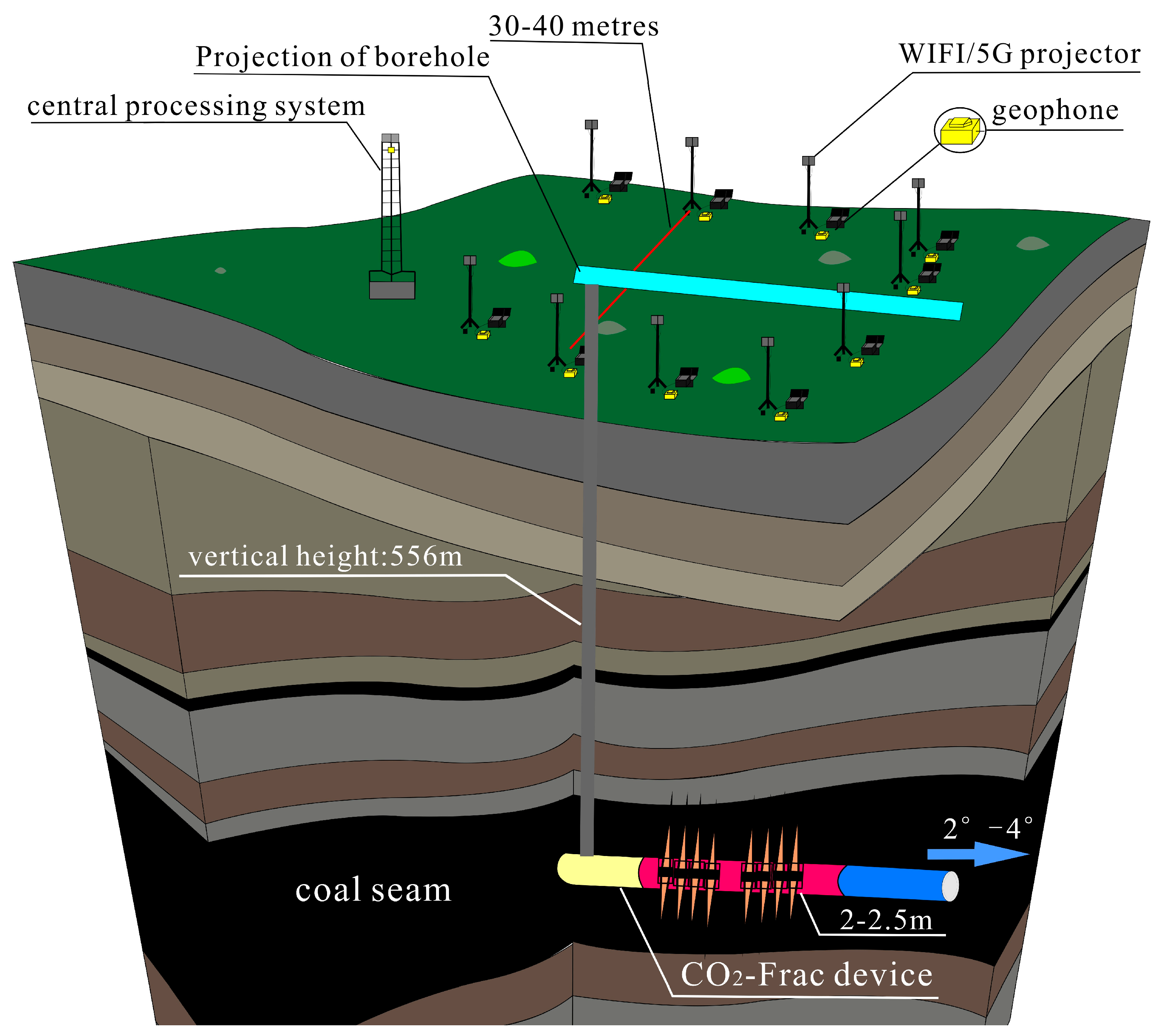
CO2-Frac is a gas blasting technology applied for directional multi-fracturing of low-permeability reservoirs and has played an important role in gas control of coal mines in recent years [1]. Figure 2 shows a schematic diagram of the CO2-Frac system. The explosion resulting from the application of CO2-Frac produces a stress wave and high-pressure expanding gas. This in turn generates a pulverized zone and a fracture zone, which increases the permeability of the coal seam and forms a stress relief zone. The connectivity of the new cracks and primary fractures within the stress relief zone acts to homogenize and release in situ stress and gas pressure, thereby greatly increasing the permeability of the coal seam.
The present study conducted three groups of parallel tests (Figure 1e): group A with a borehole depth of 75 m, direction of N0°, and 20 filled actuators; group B and group C with borehole directions of E0° and N0°, and filled actuators of 33 and 27, respectively, and both with a borehole depth of 100 m. A fracturing pressure of 120 MPa was applied to all three groups, and the mass of liquid carbon dioxide used by a single actuator was ~2.2 kg (Figure 2).

2.3. Microseismic Monitoring

Microseismic monitoring is a geophysical technique involving the observation and analysis of microseismic events and is used to monitor the influence of production activities [28]. Highly sensitive microseismic monitoring stations were established at different locations around the fracturing zone. The stations continuously recorded the microseismic data generated by the coal seam fracturing or fracture extension. The orientation, scale, mechanical properties, and stress drop of fractures were determined after deep processing and inversion.
Surface microseismic monitoring generally involves both permanent and temporary monitoring. Permanent monitoring is typically conducted over the long term to assess the risk to the safety of high-stress coal mining and underground gas storage. In contrast, temporary monitoring can persist over a few hours to several days, with the collected data used to manage temporary production activities. Between these two categories of monitoring, temporary monitoring is more widely used and is more mature. Consequently, the present study applied temporary microseismic monitoring to investigate the effect of CO2-Frac by calculating the radius of influence of CO2-Frac, inverting the resulting fracture development and stress relief, and providing reliable parameters for safe tunneling of the roadway and efficient gas extraction.
The present study established a temporary monitoring system consisting of 12 stations operated under the three-component acquisition mode. A global positioning system (GPS) was set at the front of each station to ensure a sampling rate of 1000 reads per second. The present study applied geophone sampling bits and effective bits of 32 and 22, respectively, with this system able to record a minimum earthquake magnitude of up to −3.
The present study adopted a rectangular arrangement of monitoring stations, with the long axis parallel to the drilling direction. As shown in Figure 3, in the extension direction of the testing borehole, the stations covered 1.2–1.5 times its length; and in the radial direction, the stations covered 30–40 m on both sides.

3. Methods

Microseismic monitoring associated with stress changes in and around the reservoir can be used to probe the reservoir dynamics in response to external and internal perturbations. A microseismic event analysis can be used to locate the fracturing and determine the orientation, height, length, complexity, and temporal growth of the induced fracture by using the recovered focal mechanism [29,30].
The focal mechanism of an earthquake describes the deformation in the source region that generates the seismic waves. In the case of a fault-related event, it refers to the orientation of the fault plane that slips with the slip vector, also known as a fault-plane solution. The focal mechanism is derived from a solution of the moment tensor for the earthquake, which is estimated by an analysis of observed seismic waveforms [19]. Based on the microseismic focal mechanism, a series of source parameters including stress drop, seismic moment, and magnitude can be analyzed. To achieve the main aim of quantifying the effect of primary fracture orientation on stress relief, we employed microseismic monitoring. The spatial distribution of events delineates the fracture network, while the calculated stress drop serves as a direct metric for quantifying the intensity of stress relief in different experimental groups.

3.1. Stress Drop

Microseismic events are driven by stress in the crust of the Earth. These microseismic events can result in changes to the stress field as they release and redistribute stresses accumulated during the inter-seismic period [24]. Changes in microseismic-induced stress can be observed through the inversion of the focal mechanisms of sets of microseismic events to obtain the stress orientation, with the stress drop acting as the correlation parameter [31,32,33,34,35].
Stress drop σ during an inter-seismic period is quasi-static and directly related to microseismic events, the focal medium, and in situ stress. The Brune model has been generally used to characterize the stress drop of microseismic events, typically expressed as [36]:
Δ σ = 7 16 · M 0 R 3 ,
where M 0 is the seismic moment (N·m) and R is the scale of the fracture (m).
Although the Brune model assumes a circular fault plane, it provides a robust first-order approximation for estimating stress drops associated with the complex fracture network generated by CO2 fracturing, as commonly applied in microseismic analysis [37,38]. The calculated stress-drop values are thus used for comparative analysis between experiments rather than as absolute measures.

3.2. Description of the Distribution of Stress Drop

Fracturing-related stress drop is reflected in stress disturbance around fractures, with its distribution regulated by the scale, properties, and focal mechanics of fractures. The calculated stress field induced by artificial fractures is important for describing the fracturing effect. Many previous studies have shown that stress drop has an ellipse-shaped range of influence with the fracture plane acting as its major axis and the ratio of the major axis to the minor axis of 1.3–1.6 [39,40,41,42,43].
Based on the above theory, the present study plotted cloud maps of stress drop for the three conducted experiments. The present study used the locations of the microseismic events, fracture scale, strike direction, and stress drop generated by the CO2-Frac to describe the stress drop. The discretization network model and interpolation method were used to map the distribution of stress drop, with an average ellipse axis ratio of 1.4.

4. Results and Discussions

The present study conducted three groups of microseismic monitoring tests. As shown in Figure 4, the experiments provided clear waveforms in which the traveling time of the seismic activity could be accurately distinguished.

4.1. Spatiotemporal Distribution of Microseismic Events

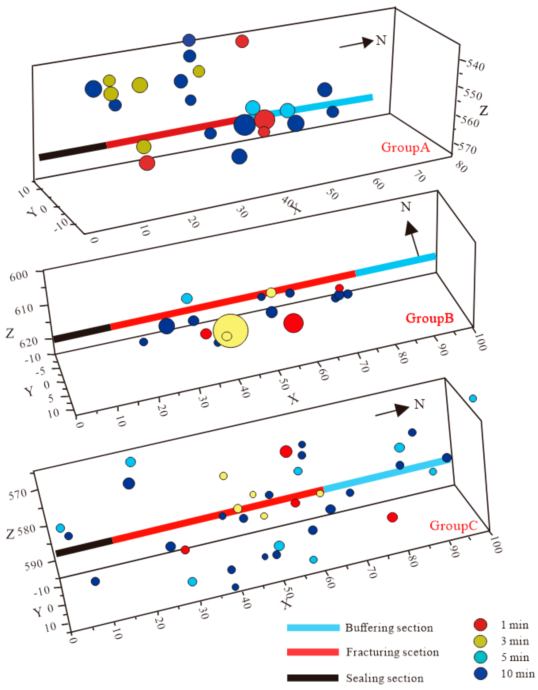
The sonic logs of the adjacent well were used to construct a detailed velocity model with 12 layers. A database of event locations was then prepared for fracture imaging. Figure 5 shows the distributions of the microseismic events at 1 min, 3 min, 5 min, and 10 min after the CO2-Frac in each group.
The microseismic events in group A were generally distributed along the N–S direction with a length of ~80 m and a sweep area in the E–W direction of ~17 m; those in group B showed a mostly concentrated distributed along the N–S direction with a length of ~60 m and an affected area in the E–W direction of ~18 m; those in group C were distributed along the N–S direction, as in group A, with an affected length and width of 110 m and 15 m, respectively. The microseismic events were uniformly distributed in strips.
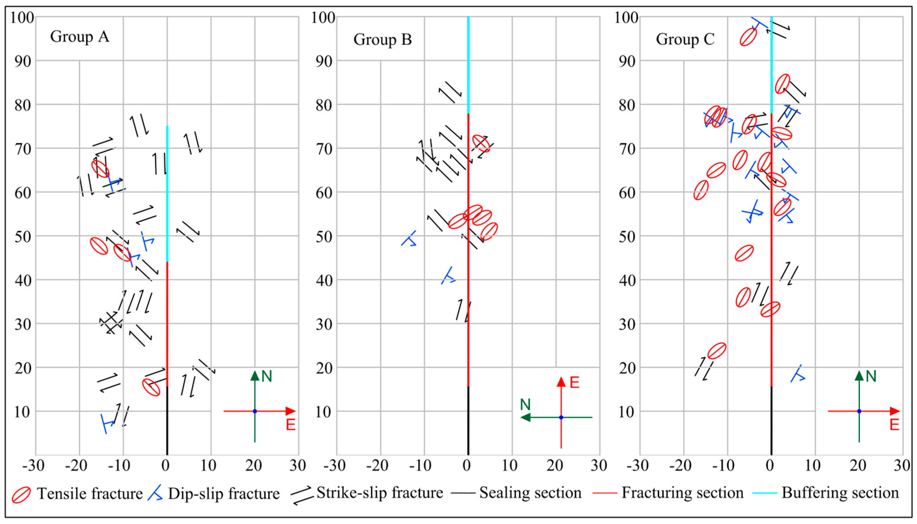
The seismic source parameters, including the fracture scale, source property, seismic moment, and stress drop, provide important information for characterizing the attributes and effects of fractures. The 77 groups of effective microseismic events obtained in the three experiments were successively extracted. These events consisted of 25, 20, and 32 groups of tensile, dip–slip, and strike–slip fractures, respectively. The scale and corresponding stress drop of the fractures ranged between 10.81 and 48.63 m and 0.24 and 1469.57 kPa, respectively. Table 1 and Figure 6 show a statistical summary of parameters and the distribution of fractures, respectively.

4.2. Shape of the Stress Relief Zone Formed by CO2-Frac

The CO2-Frac created a complex fracture network in the coal seam [44]. This network consisted of three different types of fractures: radial fractures, reopened fractures, and invisible micro-fractures. The fracture network formed by the fractures, characterized by variable properties and scales, coupled with the range of disturbance of in situ stress in the reservoir, constituted the stress relief zone.
The shape of the stress relief zone was generally ellipsoid with a volume of [25],
V = 4 π a b c / 3 ,
where a and b are the radii of the ellipsoid, representing the maximum scales of the stress disturbance in the horizontal and vertical directions in the coal reservoir, respectively, and the latter generally equivalent to the thickness of the coal seam; c represents the radius of the pole of the ellipsoid, which represents the range of the stress disturbance in the axial direction of the borehole.
The radius of the stress relief zone ( a ) in the horizontal direction was determined by the fracture scale generated by the CO2-Frac. The fracture scale can be calculated as the scale of the microseismic source.
In the Brune model, the disk radius r represents the size of the source [45]:
r = t 2 t 1 3 π · 4 2 V p
where r is the source size (m), t 1 is the take-off moment of the arrival signal, t 2 is the peak moment of the arrival signal and t 2 t 1 is the half period of microseismic event arrival signal (s), and V p is the P-wave velocity (m/s).
The P-wave velocity ( V p ) was determined by the structure of the formation in the study area, and the half period of the initial motion of the microseismic wave ( t 2 t 1 ) was related to the source frequency of the CO2-Frac. The frequency had negative and positive relationships with the half period and fracture scale, respectively.
The polar radius of the stress relief zone was calculated as:
c = c 1 + c 2 ,
where c 1 is the fracturing section of the borehole, representing the radial fracture section generated by the CO2-Frac shock wave, and c 2 is the pressure buffer section in front of the fracturing section; i.e., the reopened fracture section formed by the high-pressure gas in the buffer section in front of the borehole.
A single borehole used 10–40 actuators in which adjacent tubes were connected by a specialized wireline. Each actuator conducted one blast that produced a single set of fractures in the coal. Therefore, 20 actuators produced 20 blasts and produced 20 sets of radial fractures in the coal. The length of each actuator was 2–2.5 m. The number of actuators used in one operation was proportional to the length of borehole section being fractured. Therefore, c 1 was mainly determined by the number of actuators used in a single borehole.
The fracturing effect was optimized by reserving a 20–50 m pressure buffer section in front of the fracturing borehole. The mechanism contributing to primary fractures in the coal reservoir differed from that producing radial fractures in the fracturing section, with the former reopened by the high-pressure gas produced by the CO2-Frac in the buffer section. The re-opening of the fractures generally produced slight dislocation on the fracture surfaces, thereby releasing stress. This release of stress in the buffer section ( c 2 ) directly determined the polar radius of the ellipsoid ( c ), thereby affecting the shape of the stress relief zone.
Within extremely heterogeneous coal seams, the direction of extension of the fractures induced by CO2-Frac and its angle of intersection with the primary fractures in the coal seam have considerable influences on the fracturing effect. In general, the direction of the borehole is perpendicular to the coal wall, and the direction of the CO2-Frac is conveniently determined by the drilling direction of the borehole.
In contrast, the results of the experiments conducted in present study showed that a small angle between the drilling direction and the direction of the primary fracture produced a longer stress disturbance in the buffer section (Figure 7).
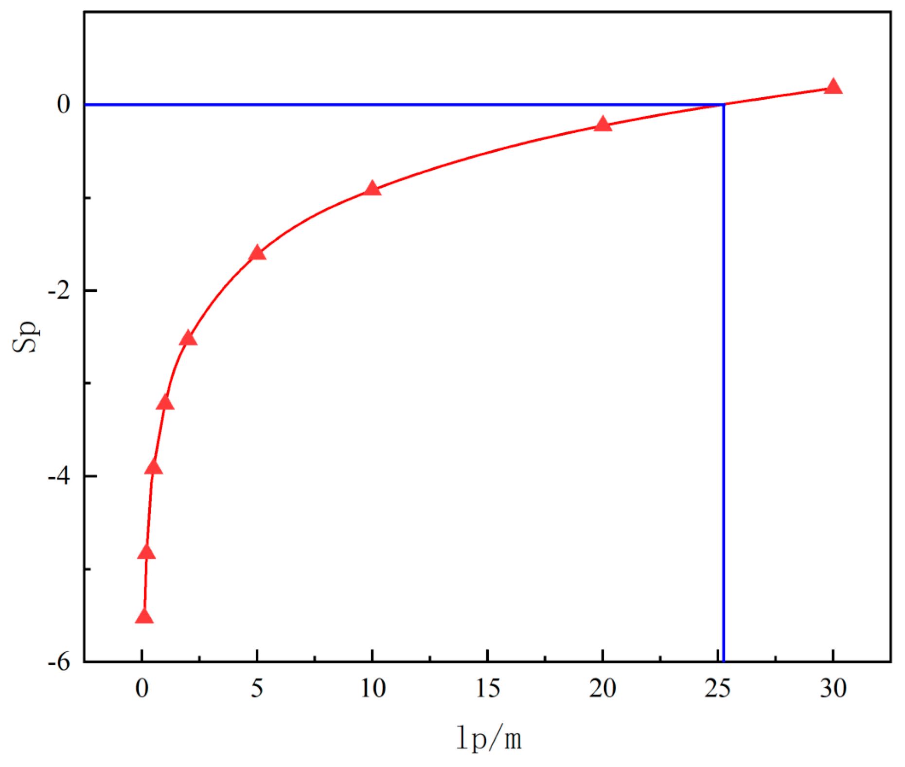
CO2-Frac fracturing is analogous to intensive perforation operations, and its improvement in the formation skin factor can be referred to as the impact of perforation operations on the skin factor [46]. proposed that the total skin factor of perforation S p f can be decomposed into the combined skin factor S p and the skin factor of perforation compaction damage S c . And the perforation geometry skin factor S p is divided into radial flow seepage skin factor S h , vertical skin factor S v , and wellbore skin factor S w b .
S p = S h + S v + S w b S h = ln ( r w / r w e ) r w e = α ( r w / l p )
In the formula, r w is the wellbore radius, m; r w e is the effective wellbore radius, m; and l p is the penetration depth of the borehole, m. Due to the large number of fractures formed by CO2-Frac and their transverse intersections, α is generally taken as 10–30.
The wellbore skin factor is S w b = C 1 e x p ( C 2 r w d ) ; among which r w d is the dimensionless wellbore radius, r w d = r w r w + l p . For CO2-Frac, C1 is generally taken as 0.001–0.1, and C2 is generally taken as 2–5.
Due to the relatively small thickness of the coal seam in the CO2-Frac operation area, the variation in the vertical skin factor S v can be ignored. And then the reservoir skin factor at different positions from the wellbore after CO2-Frac fracturing was calculated.
From Table 2 and Figure 8, it can be seen that within a range of 20 m, the skin factor is negative, and the permeability is greatly improved. The settlement results of the skin factor and the stress-drop distribution cloud map have a high degree of agreement, which confirms the transformation effect of CO2-Frac from another perspective.

4.3. Effect of the Orientation of Primary Fractures on Stress Relief and Its Rationality

Irwin divides simple cracks into three types [47]. Crack-type I, also known as tensile crack, is formed by a stress perpendicular to the crack surface; and crack-types II and III are formed under the action of shear stress, where crack-type II is the shear crack in plane, and crack-type III is the shear crack out of plane or anti-plane. All of the complex cracks can be composed of these simple cracks, which are called composite cracks. There are many mathematical methods to analyze the stress field and displacement field at the crack tip. Here, we use the complex variable function method to analyze the distribution of stress around CO2-Frac cracks.
The I-type represents the case where the displacement of the crack surface is perpendicular to the crack surface under the tensile stress perpendicular to the crack surface, so it is also called the open type. The II-type and III-type cracks represent the case where the crack surfaces slip past each other under the action of shear stress, which is called shear-type cracks. The II-type crack is called in-plane shear crack; type-III crack is called an out-of-plane shear crack or anti-plane crack. More complex cracks can be composed of these simple cracks, which are called composite cracks. There are many mathematical methods to analyze the stress field and displacement field at the crack tip. Here we use the complex variable function method.
The reopened fractures formed by the high-pressure gas were of typical composite crack-types I I I according to fracture mechanics, with the stress component in the polar coordinates of the crack front expressed as [48],
σ θ θ = 1 2 2 π r c o s θ 2 K I 1 + c o s θ 3 K I I s i n θ + o r 1 2 .
where K I is the stress intensity factor of crack-type Ι , K I I is the stress intensity factor of crack-type I I , r is the distance between point (x, y) and (0,0), θ is the angle between the crack and the maximum horizontal principal stress, and σ θ θ is the stress component.
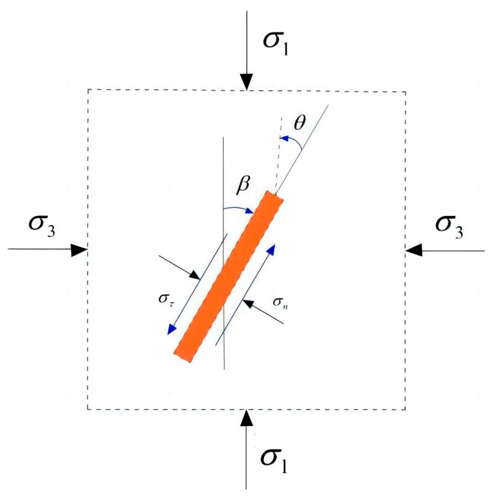
As shown in Figure 9, the maximum circumferential tensile stress criterion stipulates that a crack following the corresponding direction of θ should obey
σ θ θ θ = 0 , 2 σ θ θ θ 2 < 0 .
Under non-zero K I and K I I , Equations (1) and (2) can be simultaneously used to obtain the expression of θ :
θ = 2 a r c t a n 1 1 + 8 ( K I I / K I ) 2 4 ( K I I / K I )
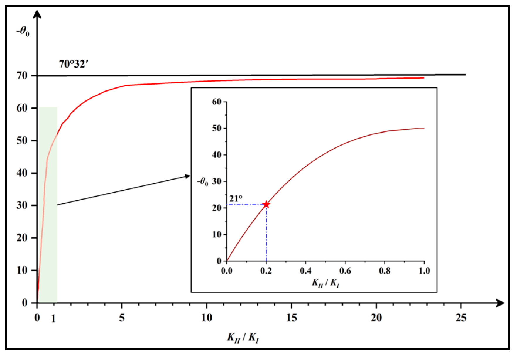
Under in situ stress, K I I K I > 0 , from which we can calculate θ < 70 ° 32 . Figure 10 shows the function curve of θ .
For the crack shown in Figure 10, under far-field stress, the expression of the stress intensity factor is:
f K = K I I K I = σ τ π a σ n π a = M c o s β + s i n β M s i n β c o s β + P 0 M .
where M = σ 1 σ 3 is the coefficient of the lateral pressure in the formation, σ 1 and σ 3 are the maximum and minimum stresses in the horizontal direction, respectively, P 0 is the pore pressure after gas fracturing, and β is the included angle between the crack strike and the maximum stress in the horizontal direction, which is equal to σ in Figure 9.
The extreme value of K I I K I can be obtained based on the analytical solution of f K = 0 . The present study calculated the trend in variation of K I I K I under different lateral pressure coefficients and pore pressures using the trial solution method (Figure 11a,b).
In the coal mining area, the coefficient of the lateral pressure and pore pressure after CO2-Frac were generally 1–2.5 and 20–100 MPa, respectively. As represented by the yellow area in Figure 10, under these conditions, the range of the change in K I I K I was 0–0.2. θ was calculated to be 0–21° by substituting the range of variation of K I I K I into Equation (8) [49,50,51,52,53,54].
The field experiments show that the smaller the angle between the direction of the fracturing borehole and the maximum horizontal principal stress, the better the pressure relief effect. The results of theoretical calculations further validate and quantify this conclusion, suggesting that the pressure relief effect of CO2-Frac is optimal when the angle range is 0–21°.
The results of the present study can provide theoretical guidance for the optimization of CO2-Frac [55]. Optimized stress release was achieved by adopting a direction of the fracturing borehole parallel to the cleat to form increasingly tensile fractures through the application of a large quantity of CO2 gas.

5. Conclusions

In this study, microseismic monitoring was conducted for three CO2-Frac boreholes in Xinyuan coalmine, China. The results provide a differential distribution of stress drop in the testing borehole, which can increase the understanding of the effect of primary fracture orientation on CO2-Frac. Based on the results of this study, the following conclusions can be drawn.
(1) Stress drop and the range of the buffer section varied greatly, with the degree of stress release an important index influencing the effect of CO2-Frac.
(2) The fractures in the buffer section extended from the fracturing section, with their length affected by the angle between the orientation of the borehole and the direction of the primary fracture. Furthermore, the effect of stress release in the buffer section decreased as the angle increased.
(3) Fracture mechanics modeling confirms that the optimal stress relief is achieved when the angle BF is within 0–21°, which aligns well with the field observations. It should be noted that this optimal range is derived from the specific conditions of this study and may vary with in situ stress regimes and coal properties.

Author Contributions

Methodology, P.L., D.Z. and L.T.; Resources, P.L., W.H. and L.T.; Data curation, P.L., Z.W. and W.H.; Writing—original draft, P.L., D.Z., Z.W. and L.T.; Writing—review & editing, L.T. All authors have read and agreed to the published version of the manuscript.

Funding

This research received no external funding.

Data Availability Statement

The original contributions presented in this study are included in the article. Further inquiries can be directed to the corresponding author(s).

Conflicts of Interest

The authors declare that they have no known competing financial interests or personal relation-ships that could have appeared to influence the work reported in this paper.

References

  1. Cao, Y.; Zhang, J.; Zhai, H.; Fu, G.; Tian, L.; Liu, S. CO2 gas fracturing: A novel reservoir stimulation technology in low permeability gassy coal seams. Fuel 2017, 203, 197–207. [Google Scholar] [CrossRef]
  2. Liu, X.; Nie, B.; Guo, K.; Zhang, C.; Wang, Z.; Wang, L. Permeability enhancement and porosity change of coal by liquid carbon dioxide phase change fracturing. Eng. Geol. 2021, 287, 106106. [Google Scholar] [CrossRef]
  3. Hou, L.; Zhang, S.; Elsworth, D. Review of fundamental studies of CO2 fracturing: Fracture propagation, propping and permeating. J. Pet. Sci. Eng. 2021, 205, 108823. [Google Scholar] [CrossRef]
  4. Li, Y.; Wang, Y.; Bi, C. Assessment of in-situ CO2 Sequestration Potential and Enhanced Coalbed Methane (ECBM) Production of Continental Coal-bearing Basins in China. Acta Geol. Sin.-Engl. Ed. 2024, 98, 1602–1614. [Google Scholar] [CrossRef]
  5. Ugwele, F.O.; Chime, T.O. Comparative Study of The Different Methods of Purifying Used Mobil Oil Using Different Acids as Washing Agents. Int. J. Nov. Res. Eng. Sci. 2019, 6, 1–6. [Google Scholar]
  6. Hughes, R.V.; Pfister, R.J. Advantages of brines in secondary recovery of petroleum by water-flooding. Trans. AIME 1947, 170, 187–201. [Google Scholar] [CrossRef]
  7. Tai, L.; Li, C.; Hu, Y.; Yu, X.; Xu, Z.; Zhang, X.; Chai, S.; Zhang, P.; Lu, S. Experimental study on the significance of pressure relief effect and crack extension law under uniaxial compression of rock-like materials containing drill holes. Sci. Rep. 2024, 14, 1104. [Google Scholar] [CrossRef]
  8. Zhang, Y.; Chen, Y.; Zhang, S.; Feng, G.; Wang, Y.; Li, S.; Wang, Q.; Wang, B.; Zhao, L. Study on the Influence of Drilling Parameters on the Mechanical Properties and Pressure Relief Effect of Coal Rock. Processes 2025, 13, 993. [Google Scholar] [CrossRef]
  9. Liu, H.; Hao, W. Application research of liquid CO2 fracturing in coal seam penetration. Earth Environ. Sci. 2020, 526, 12095. [Google Scholar] [CrossRef]
  10. Shang, Z.; Wang, H.; Li, B.; Cheng, Y.; Zhang, X.; Zhao, F.; Zhang, X.; Hao, C.; Wang, Z. Fracture processes in coal measures strata under liquid CO2 phase transition blasting. Eng. Fract. Mech. 2020, 254, 107902. [Google Scholar] [CrossRef]
  11. Sampath, K.H.S.M.; Perera, M.S.A.; Elsworth, D.; Ranjith, P.G.; Matthai, S.K.; Rathnaweera, T.; Zhang, G. Effect of coal maturity on co2-based hydraulic fracturing process in coal seam gas reservoirs. Fuel 2019, 236, 179–189. [Google Scholar] [CrossRef]
  12. Jiang, Y.; Qin, C.; Kang, Z. Experimental study of supercritical CO2 fracturing on initiation pressure and fracture propagation in shale under different triaxial stress conditions. J. Nat. Gas Sci. Eng. 2018, 55, 382–394. [Google Scholar] [CrossRef]
  13. Zhou, W.; Shi, G.; Wang, J.; Liu, J.; Xu, N.; Liu, P. The influence of bedding planes on tensile fracture propagation in shale and tight sandstone. Rock Mech. Rock Eng. 2022, 55, 1111–1124. [Google Scholar] [CrossRef]
  14. Kursunoglu, N.; Onder, M. Application of structural equation modeling to evaluate coal and gas outbursts. Tunn. Undergr. Space Technol. 2019, 88, 63–72. [Google Scholar] [CrossRef]
  15. Li, W.; Ren, T.; Busch, A.; Hartog, S.A.M.D.; Cheng, Y.; Qiao, W.; Li, B. Architecture, stress state and permeability of a fault zone in Jiulishan coal mine, China: Implication for coal and gas outbursts. Int. J. Coal Geol. 2018, 198, 1–13. [Google Scholar] [CrossRef]
  16. Li, L.; Tan, J.; Tan, Y.; Pan, X.; Zhao, Z. Microseismic analysis to aid gas reservoir characterization. Sustain. Geosci. Nat. Gas Subsurf. Syst. 2022, 2, 219–242. [Google Scholar]
  17. Tan, Y.; Wang, J.; Rijken, P.; Zhang, Z.; Fang, Z.; Wu, R.; Ning, I.L.C.; Liu, X. Mechanism of microseismic generation during hydraulic fracturing. In Proceedings of the Unconventional Resources Technology Conference (URTeC), Houston, TX, USA, 26–28 July 2021; pp. 1146–1161. [Google Scholar] [CrossRef]
  18. Li, L.; Tan, J.; Wood, D.A.; Zhao, Z.; Becker, D.; Lyu, Q.; Shu, B.; Cheng, H. A review of the current status of induced seismicity monitoring for hydraulic fracturing in unconventional tight oil and gas reservoirs. Fuel 2019, 242, 195–210. [Google Scholar] [CrossRef]
  19. Tian, L.; Cao, Y.; Liu, S.; Shi, B.; Elsworth, D. Coalbed methane reservoir fracture evaluation through the novel passive microseismic survey and its implications on permeable and gas production. J. Nat. Gas Sci. Eng. 2020, 76, 103181. [Google Scholar] [CrossRef]
  20. Tian, L.; Li, Z.; Cao, Y.; Liu, S.; Song, Y. In situ stress distribution and variation monitored by microseismic tracking on a fractured horizontal well: A case study from the Qinshui Basin. Acs Omega 2022, 7, 14363–14370. [Google Scholar] [CrossRef] [PubMed]
  21. Besedina, A.N.; Kishkina, S.B.; Kocharyan, G.G. Source parameters of microseismic swarm events induced by the explosion at the Korobkovskoe Iron Ore deposit. Izv. Phys. Solid Earth 2021, 57, 348–365. [Google Scholar] [CrossRef]
  22. Duncan, P.M. Is there a future for passive seismic? First Break 2005, 23, 111–115. [Google Scholar] [CrossRef]
  23. Wojtecki, U.; Konicek, P.; Mendecki, M.J.; Goda, I.; Zuberek, W.M. Geophysical evaluation of effectiveness of blasting for roof caving during longwall mining of coal seam. Pure Appl. Geophys. 2020, 177, 905–917. [Google Scholar] [CrossRef]
  24. Urbancic, T.I.; Trifu, C.I. Microseismic identification of stress transfer as related to rockburst occurrences. In Series on Rock and Soil Mechanics; Trans Tech Publications: Clausthal-Zellerfeld, Germany, 1998; pp. 357–369. [Google Scholar]
  25. Cao, Y.; Tian, L.; Fan, Y.; Liu, J.; Zhang, S. Study on cracking ring form of carbon dioxide gas phase fracturing in low permeability coal seam. Coal Sci. Technol. 2018, 46, 46–51. [Google Scholar]
  26. Cao, T.; Yang, Z.; Qin, Y.; Li, C. Characteristics of modern geo-stress and removability of no.15 coal reservoir, Yangquan mining area, China. Nat. Resour. Res. 2021, 30, 2211–2223. [Google Scholar] [CrossRef]
  27. Lyu, S.; Wang, S.; Chen, X.; Wang, S.; Wang, T.; Shi, X.; Dong, Q.; Li, J. Natural fractures in soft coal seams and their effect on hydraulic fracture propagation: A field study. J. Pet. Sci. Eng. 2020, 192, 107255. [Google Scholar] [CrossRef]
  28. Al-Attar, H.H.; Barkhad, F.A. A review of unconventional natural gas resources. J. Nat. Sci. Sustain. Technology. 2019, 12, 263–288. [Google Scholar]
  29. Maxwell, S. Microseismic: Growth born from success. Lead. Edge 2010, 29, 338–343. [Google Scholar] [CrossRef]
  30. Maxwell, S.C.; Urbancic, T.I. The role of passive microseismic monitoring in the instrumented oil field. Lead. Edge 2001, 20, 636–640. [Google Scholar] [CrossRef]
  31. Baltay, A.; Ide, S.; Prieto, G.; Beroza, G. Variability in earthquake stress drop and apparent stress. Geophys. Res. Lett. 2011, 38, L06303. [Google Scholar] [CrossRef]
  32. Cotton, F.; Archuleta, R.; Causse, M. What is sigma of the stress drop? Seism. Res. Lett. 2013, 84, 42–48. [Google Scholar] [CrossRef]
  33. Huang, Y.; Beroza, G.C.; Ellsworth, W.L. Stress drop estimates of potentially induced earthquakes in the guy-greenbrier sequence. J. Geophys. Res. Solid Earth 2016, 121, 6597–6607. [Google Scholar] [CrossRef]
  34. Lengliné, O.; Lamourette, L.; Vivin, L.; Cuenot, N.; Schmittbuhl, J. Fluid-induced earthquakes with variable stress drop. J. Geophys. Res. Solid Earth 2014, 119, 8900–8913. [Google Scholar] [CrossRef]
  35. Noda, H.; Lapusta, N.; Kanamori, H. Comparison of average stress drop measures for ruptures with heterogeneous stress change and implications for earthquake physics. Geophys. J. Int. 2013, 193, 1691–1712. [Google Scholar] [CrossRef]
  36. Klinger, A.G.; Werner, M.J. Stress drops of hydraulic fracturing induced microseismicity in the horn river basin: Challenges at high frequencies recorded by borehole geophones. Geophys. J. Int. 2022, 228, 2018–2037. [Google Scholar] [CrossRef]
  37. Li, H.; Chang, X. A review of the microseismic focal mechanism research. Sci. China Earth Sci. 2021, 64, 351–363. [Google Scholar] [CrossRef]
  38. Li, Z.; Chang, X.; Yao, Z.; Wang, Y. Fracture monitoring and reservoir evaluation by micro-seismic method. Chin. J. Geophys. 2019, 62, 707–719. (In Chinese) [Google Scholar]
  39. Shao, S.; Chen, K.; Ding, W.; Yang, G.; Tang, J. Stress field analytic model and stress perturbation analysis around hydraulic cracks. China Pet. Mach. 2018, 46, 108–114. [Google Scholar] [CrossRef]
  40. Sneddon, I.N. The distribution of stress in the neighborhood of a crack in an elastic solid. Proc. R. Soc. A Math. Phys. Eng. Sci. 1946, 1009, 229–260. [Google Scholar] [CrossRef]
  41. Su, S.; Stephansson, O. Effect of a fault on in situ stresses studied by the distinct element method. Int. J. Rock Mech. Min. 1999, 36, 1051–1056. [Google Scholar] [CrossRef]
  42. Su, S.; Zhu, H.; Wang, S.; Stephansson, O. Effect of physical and mechanical properties of rocks on stress field in the vicinity of fractures. Chin. Int. J. Rock Mech. Min. 2003, 22, 370–377. [Google Scholar] [CrossRef]
  43. Zhou, J.; Chen, M.; Jin, Y.; Zhang, G. Analysis of fracture propagation behavior and fracture geometry using a tri-axial fracturing system in naturally fractured reservoirs. Int. J. Rock Mech. Min. Sci. 2008, 45, 1143–1152. [Google Scholar] [CrossRef]
  44. Jia, J.; Wang, D.; Li, B.; Tian, X. Study of the influencing factors of the liquid CO2 phase change fracturing effect in coal seams. PLoS ONE 2021, 16, 254996. [Google Scholar] [CrossRef] [PubMed]
  45. Brune, J.N. Tectonic stress and the spectra of seismic shear waves from earthquakes. J. Geophys. Res. 1970, 75, 4997–5009. [Google Scholar] [CrossRef]
  46. Zeng, W.; Mi, Q. Skin coefficient decomposition calculation of horizontal well after perforation. Drill. Fluid Complet. Fluid 2005, 22, 105–106. [Google Scholar]
  47. Irwin, G.R. Analysis of stresses and strains near end of a crack traversing a plate. J. Appl. Mech. 1956, 24, 361–364. [Google Scholar] [CrossRef]
  48. Li, S.Y.; He, T.; Yin, X. Introduction of Rock Fracture Mechanics; University of Science and Technology of China Press: Hefei, China, 2010. [Google Scholar]
  49. Hu, Q.; Liu, L.; Li, Q.; Wu, Y.; Wu, X. Experimental investigation on crack competitive extension during hydraulic fracturing in coal measures strata. Fuel 2020, 265, 117003. [Google Scholar] [CrossRef]
  50. Liang, X.; Hou, P.; Xue, Y.; Gao, Y.; Gao, F.; Liu, J.; Dang, F. Role of fractal effect in predicting crack initiation angle and its application in hydraulic fracturing. Rock Mech. Rock Eng. 2022, 55, 5491–5512. [Google Scholar] [CrossRef]
  51. Liu, Q.; Zhao, Y.; Tang, L.; Liao, J.; Wang, X.; Tan, T.; Chang, L.; Luo, S.; Wang, M. Mechanical characteristics of single cracked limestone in compression-shear fracture under hydro-mechanical coupling. Theor. Appl. Fract. Mech. 2022, 119, 103371. [Google Scholar] [CrossRef]
  52. Pan, J.; Li, D.; Cai, S.; Luo, X. A pure complex variable enrichment method for modeling progressive fracture of orthotropic functionally gradient materials. Eng. Fract. Mech. 2023, 277, 108984. [Google Scholar] [CrossRef]
  53. Zhao, Y.; Zhang, L.; Wang, W.; Pu, C.; Wan, W.; Tang, J. Cracking and stress–strain behavior of rock-like material containing two flaws under uniaxial compression. Rock Mech. Rock Eng. 2016, 49, 2665–2687. [Google Scholar] [CrossRef]
  54. Zhao, X.; Huang, B.; Xu, J. Experimental investigation on the characteristics of fractures initiation and propagation for gas fracturing by using air as fracturing fluid under true triaxial stresses. Fuel 2019, 236, 1496–1504. [Google Scholar] [CrossRef]
  55. Tan, Y.; Fang, Z.; Liu, X.; Fradelizio, G.; John, E. The impact of in-situ shear stress on microseismic temporal-magnitude patterns. In Proceedings of the 56th US Rock Mechanics/Geomechanics Symposium, Santa Fe, NM, USA, 26–29 June 2022. [Google Scholar] [CrossRef]
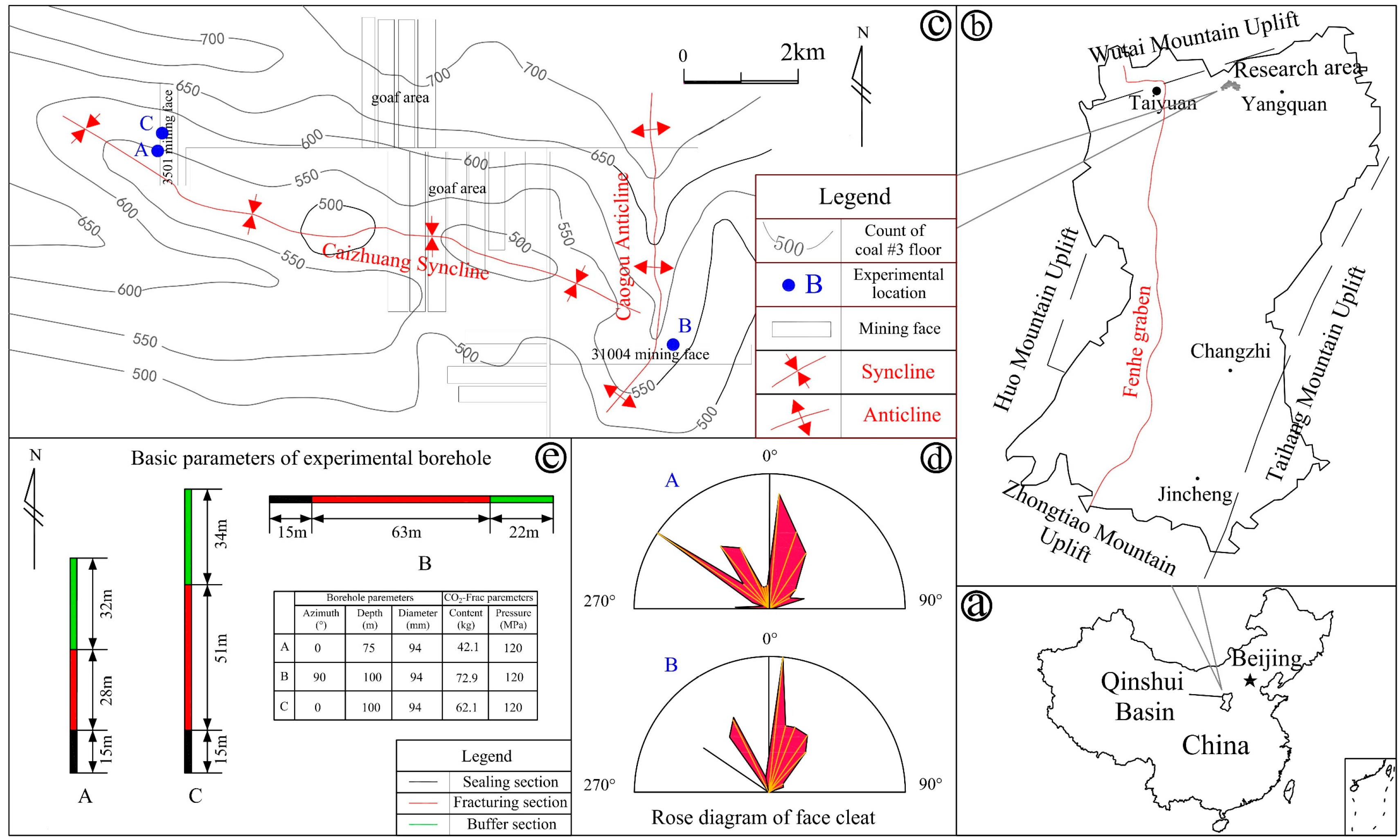
Figure 1. Schematic diagram of the basic parameters of the experimental area. (a) Location of the study area; (b) Location of the test site; (c) Contours of the No. 3 coal seam floor near the study area; (d) Rose diagram of face cleat; (e) Basic parameters of experimental borehole.
Processes 13 03523 g001
Figure 2. Schematic diagram of the CO2-Frac device.
Processes 13 03523 g002
Figure 3. Schematic diagram of the layout of the microseismic monitoring ground stations implemented in the present study.
Processes 13 03523 g003
Figure 4. Seismic waveforms produced by CO2-Frac.
Processes 13 03523 g004
Figure 5. Distributions of microseismic events from 1 to 10 min after CO2-Frac.
Processes 13 03523 g005
Figure 6. Distribution of different types of microseismic sources.
Processes 13 03523 g006
Figure 7. Stress-drop cloud maps for the three experiments conducted in the present study for (a) Group A, (b) Group B, and (c), Group C.
Processes 13 03523 g007
Figure 8. Map of crack location and skin coefficient relationship.
Processes 13 03523 g008
Figure 9. Stress components in polar coordinates of the fracture front.
Processes 13 03523 g009
Figure 10. The relationship between the fracture angle ( θ ) and ratio ( K I I / K I ) (Adapted from [48]).
Processes 13 03523 g010
Figure 11. The trends in variation under different (a) lateral pressure coefficients and, (b) pore pressures.
Processes 13 03523 g011
Table 1. A statistical summary of the source properties of microseismic events.
Test SerialSeismic DotsFocal MechanismFracture Scale (m)Stress Drop (kPa)
TensileDip–SlipStrike–Slip
Group A23441516.21–34.220.24–569.81
Group B1652910.81–48.631.53–1469.57
Group C381614810.81–18.0124.62–992.72
Table 2. Comparison of crack location and skin coefficient relationship.
l p α r w r w e r w d C 1 C 2 S h S w b S p
0.1250.06150.3750.00053−5.52150.0015−5.5199
0.2250.067.50.2307690.00053−4.82830.0010−4.8273
0.5250.0630.1071430.00053−3.91200.0007−3.9113
1250.061.50.0566040.00053−3.21890.0006−3.2183
2250.060.750.0291260.00053−2.52570.0005−2.5252
5250.060.30.0118580.00053−1.60940.0005−1.6089
10250.060.10.0059640.00053−0.91630.0005−0.9158
20250.060.0750.0029910.00053−0.22310.0005−0.2226
30250.060.050.0019960.000530.18230.00050.1828
Disclaimer/Publisher’s Note: The statements, opinions and data contained in all publications are solely those of the individual author(s) and contributor(s) and not of MDPI and/or the editor(s). MDPI and/or the editor(s) disclaim responsibility for any injury to people or property resulting from any ideas, methods, instructions or products referred to in the content.