Article

Selective Recovery of Rare Earth Elements from Electric Motors in End-of-Life Vehicles via Copper Slag for Sustainability

1
Industrial Science Technology Research Center, Pukyong National University, Busan 48513, Republic of Korea
2
Darkhan School of Technology, Mongolian University of Science and Technology, Darkhan City 45051, Mongolia
3
Department of Metallurgical Engineering, School of Engineering, Pukyong National University, Busan 48513, Republic of Korea
4
Electrification PE Materials Development Team, Hyundai Motor Co., Hwaseong 18280, Republic of Korea
*
Author to whom correspondence should be addressed.
Processes 2025, 13(11), 3502; https://doi.org/10.3390/pr13113502
Submission received: 14 October 2025 / Revised: 28 October 2025 / Accepted: 30 October 2025 / Published: 31 October 2025

Abstract

Discarded NdFeB permanent magnets will become a significant source of rare earth elements (REEs) in the future. Electric vehicle (EV) motors utilize 2–5 kg of NdFeB magnets, and researchers are prioritizing the development of suitable extraction technologies. The objective of our research is to separate metal materials (Al, Cu, Fe and FEEs) from EV motors, based on their melting temperatures. REE magnets that pose the greatest challenge are melted together with the electrical steel of the motor, and the potential for extracting REEs in a selective manner from the molten steel was examined based on their significant oxidation potential using FeO–SiO2 compounds, which act as an oxidizing slag-forming agent, to test the extraction method. Fayalite (2FeO·SiO2) is the most easily created and ideal eutectic compound for carrying oxygen (FeO) and forming slag ( S i O 4 4 ), typically generated during copper smelting. In this experiment, copper slag was used and the results were compared to a smelting test, which had previously used a synthesized fayalite flux as a model. The smelting test, utilizing synthesized fayalite flux, yielded a 91% Nd recovery rate. The Nd recovery rate in the smelting test with copper slag hit a high of 64.81%, influenced by the smelting’s holding time. The steel contained 0.08% Nd. Iron was recovered from the copper slag at a rate of 73%. During the smelting test, it was observed that the reaction between Nd2O3 and the Al2O3 crucible resulted in the formation of a layer on the surface of the crucible, diffusion into the crucible itself, and a subsequent reduction in the efficiency of Nd recovery.

1. Introduction

Rare earth elements are categorized into two groups, namely light REEs and heavy REEs; however, given their substantial and growing demand in contemporary applications, Nd, Y, Eu, Tb, and Dy are also classified as critical REEs, highlighting their crucial role in modern technologies [1,2,3]. Nature contains REEs in diverse geological formations and minerals; the most prevalent and economically useful sources include bastnäsite, monazite, loparite, and lateritic ion-adsorption clays. China’s Bayan Obo deposit, rich in light REEs like Nd and Ce, provides over 80% of the global supply, with carbonate deposits being a major source [4,5,6]. From 2019 to 2024, the REE market saw consistent growth, rising from USD 4 billion to USD 12.44 billion, and IMARC Group predicts a market value of USD 37.06 billion by 2032 [7,8]. REE production rose from roughly 240,000 metric tons in 2020 to 390,000 in 2024. Global REE sales in 2024 were dominated by China (almost 70%), with contributions also coming from the USA, Myanmar, Australia, Thailand, and other countries [9,10]. REEs play a critical role in applications such as permanent magnets, NiMH batteries, auto catalysts, diesel engines, fluid cracking catalysts, phosphors, glass, polishing powders, and other advanced technologies. Electric vehicle (EV) motors and wind turbines use NdFeB magnets, contributing to 30–35% and 15–20% of total REE consumption, respectively, in 2024, totaling over 50% [11,12,13]. NdFeB magnets, which are strong permanent magnet materials, contain 29–32% Nd, 64–66% Fe, and 1–2% B, along with small quantities of REEs like Dy, Nb, Ga, and Tb to enhance their properties [14,15,16]. NdFeB magnets, which are vital for EV motors’ high efficiency and power density, are key components in permanent magnet synchronous motors (PMSMs), demanding 2–5 kg per EV [17,18]. Direct-drive generators in onshore and offshore wind turbines use approximately 600 kg of NdFeB magnets per megawatt of capacity [19,20]. Furthermore, the widespread applications of NdFeB magnets span diverse sectors, encompassing consumer electronics (including speakers, microphones, hard disk drives (HDDs), and vibration motors), industrial motors, and automation technologies vital to Industry 4.0 (such as servo motors and robotics), the medical field (specifically MRI scanners), aerospace and defense applications (using actuators, sensors, and guidance systems), and a multitude of other advanced technological domains.
As statistics show, AI-powered EV systems are key to the 4.0 Industrial Revolution’s progress and are projected to substantially influence the field [21,22]. Citing sources, IHS Markit reported that global EV sales in 2024 exceeded 17 million units, with key players including BYD, NIO, Volkswagen, and BMW significantly boosting market share [23,24,25]. Bloomberg NEF’s projections, building upon prior data, suggest that EVs will represent a substantial 50% of worldwide vehicle sales by 2035 [26]. Green energy and EV growth will fuel continuous expansion of NdFeB magnet use in the coming decades, according to the aforementioned research. This has caused worry over the sourcing and supply of REEs. Although end-of-life products represent a substantial potential source of REEs, studies (Danouche et al. [27] and Cherkezova et al. [28]) show that recycling rates are currently only about 1%. A large amount of NdFeB magnet scrap from EVs and wind turbines is expected over the next ten years, creating a significant REE recovery opportunity. Our research focused on EV motors, building upon our previous work [29] which showed the potential for a single-furnace pyrometallurgical process capable of isolating copper, aluminum, and iron materials, while simultaneously integrating REEs into the slag, which is a separation made possible by the varying melting points of these metals. The development and introduction of robotic machines for the disassembly and component sorting of end-of-life EV motors are attributable to inventors such as Zushi et al. [30], Tiwari et al. [31], Chang et al. [32], and Mitrouchev et al. [33]. However, the varied designs and sizes of motors, coupled with low mass production output and high costs, pose challenges for these robots. A study by Katsunori et al. [34], similar to our research, introduced the smelting of NdFeB magnets with motor rotors to separate REEs using the RexOy–Na2B4O7 slag system. Moreover, the studies by Saito et al. [35] (Nd2O3–B2O3 slag) and Yang et al. [36] (CaO–SiO2–Al2O3 slag) both successfully separated REEs from NdFeB magnets, showing REE dissolution in the slag. As the crucial raw material for the next steps in hydrometallurgical processing, the slag, which includes the compound RexOy, is used. As shown in Scheme 1, metal materials (Al, Cu, and Fe) from EV motors are sequentially melted and separated at their individual melting points (~700 °C, ~1100 °C, and ~1600 °C). During smelting, the NdFeB magnet elements and the motor’s electrical steel combine; the REEs dissolve in the molten iron, and their strong oxidation potential differences cause them to separate as oxides from the liquid metal. In this smelting, copper slag acts as an oxidant, in form of the fayalite (2FeO·SiO4) structure where FeO functions as an oxygen carrier, while SiO2 acts as a slag former; simultaneously, SiO2 plays a dual role by creating 2RexO·SiOy silicate with RexOy (REE oxides), thus incorporating it into the slag structure. Furthermore, this strongly supports the ongoing discussions surrounding sustainable material policies, demonstrating a significant leap forward in advanced recycling technology. Our previous work [29] achieved a 91% REE separation rate, employing selective extraction with a slag system using a synthetic fayalite flux. This study presents a comparison of real copper slag obtained from the Ls MnM copper smelting plant in Korea and the results of experiments that used synthetic fayalite flux. The purpose of this research is to examine the feasibility of extracting REEs using copper slag in steel production, which is a process that smelts with NdFeB magnets, in addition to the optimization of copper slag usage. The study also included an examination of the time needed for the complete dissolution of the NdFeB magnet in liquid steel, while also looking into how the oxygen carrier additive Fe2O3 affected the process of REE extraction. Additionally, the potential economic benefits of separating iron and copper from the copper slag were highlighted.

2. Materials and Methods

2.1. Experimental Materials

Utilizing a scaled-down simulation methodology in a laboratory environment, experiments were performed on the smelting of EV motor steel in combination with NdFeB magnets. The chemical compositions of the simulation material (rotor steel) and carbonization material (cast iron flakes) are listed in Table 1. The stator and rotor, the core components of this material, are made from electrical steel, which is a material chosen for its superior magnetic properties and minimal energy loss, as demonstrated in the studies cited in references [37,38]. The composition of electrical steel (silicon steel) consists of roughly 3% Si, with C less than 0.05%, Mn at 0.45%, approximately 0.05% Al, and S and P levels each less than 0.03%. The composition of these cast iron flakes includes significant amounts of C at about 3.5%, and 2.6% of Si, while P and S are present in lesser amounts, at 0.34% and 0.13%, respectively. For this experiment, we directly removed and used an NdFeB magnet from the rotor. The composition of an NdFeB magnet includes a main blend of Nd at approximately 30%, Fe at approximately 66%, and B at approximately 2%, with minor additions of REEs such as Dy, Nb, Ga, and Tb.
Copper slag from Ls-MnM Co., Ltd.’s copper smelting plant in Onsan–eup, Republic of Korea was used as an oxidizer and slag-forming flux. Used directly in the experiment, the glassy black, amorphous, fine-grained copper slag required no additional crushing or grinding. The chemical composition of the slag flux is shown in Table 2. Analysis revealed that Fe2O3 and SiO2 constituted the primary oxides, with percentages of 55.45 and 41.49, respectively. The copper slag differed from the synthetized fayalite flux in previous experiments [29], containing 4.81% of Al2O3, 1.93% of MgO, and 1.85% of CaO. Furthermore, analysis revealed the presence of 1.41% of CuO and 1.16% of ZnO in the copper slag.
Figure 1 shows the XRD (X-ray diffractometer) analysis of synthetic copper slag flux. Analysis revealed fayalite (Fe2SiO4-01-071-1672 DB card number), primarily composed of FeO and SiO2. In our previous simulation experiments, the synthesized fayalite flux consisted of a structure that closely mirrored the fayalite structure found within the copper slag.

2.2. Experimental Apparatus and Procedure

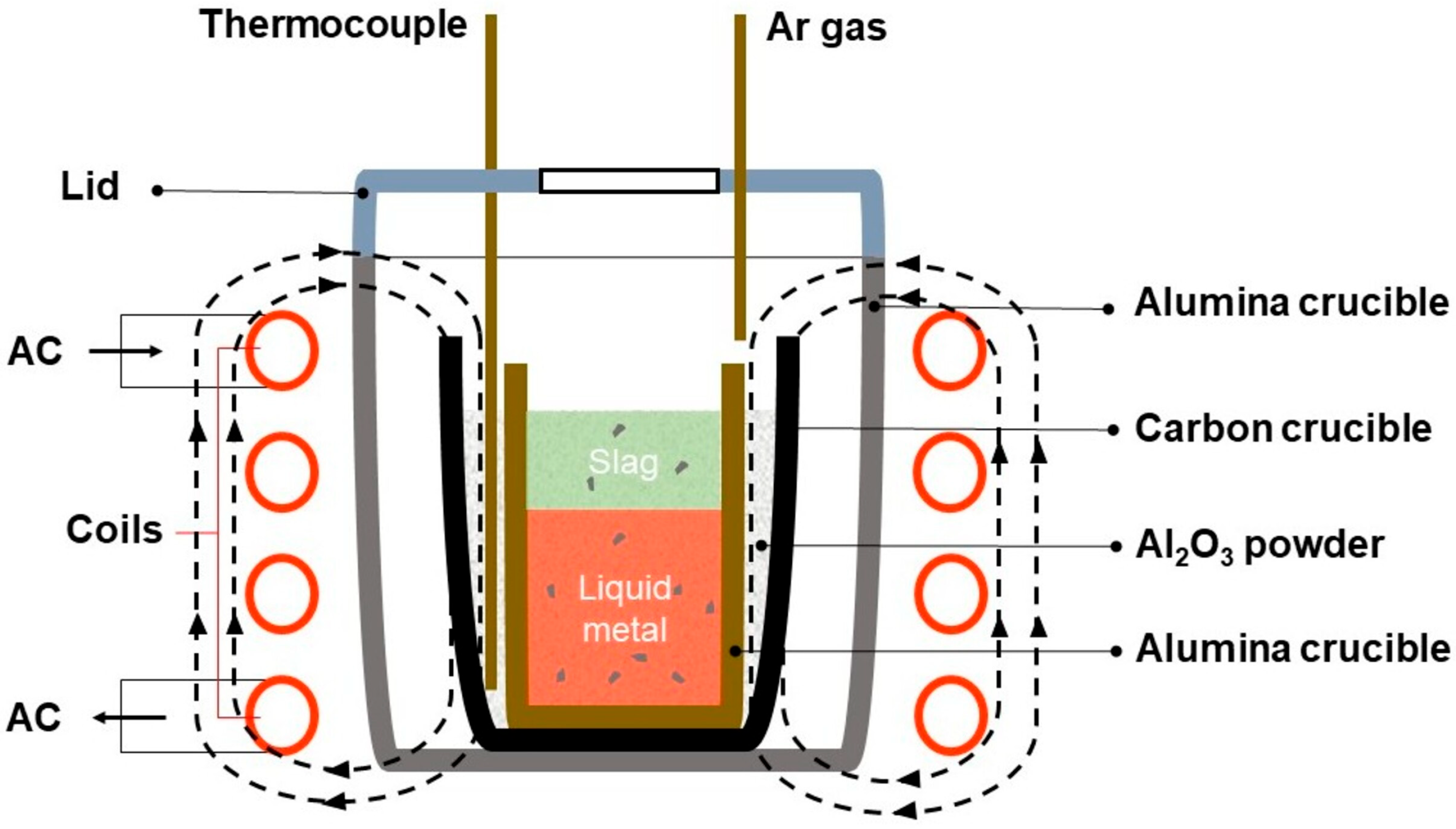
The experiment was conducted using a 30 kHz high-frequency induction furnace for the purpose of the experiment. A cooler, a controller, and a heater were all components of the furnace. The organization and composition of the experimental setup used in this investigation are thoroughly illustrated in a schematic diagram, which is shown in Figure 2. The samples were held within alumina crucibles that were placed inside graphite crucibles, which were used as heaters. A thermometer was positioned between graphite and alumina crucibles, with Al2O3 powder surrounding it, serving as insulation. With programmed settings, the experimental induction furnace was operated using the NP200 model thermo-controller made by Hanyoung Nux Co., Ltd., in Incheon city, Republic of Korea. By maintaining the furnace temperature above 1550 °C during adjustments, this method compromises the precision of the temperature of the liquid metal. With a channeled lid in place, argon and other materials were securely sealed inside the furnace. With a flow rate of 300 cc/min, argon gas was used to protect the crucible as it underwent both heating and cooling. After the material was completely melted, the process included a hold that lasted for 10, 20, and 30 min. After adding the oxidizer and flux agents one after another, with 10 min between each addition, the experiment came to an end. The furnace was steadily heated to 1550 °C at 20 °C/min. The sample, which was placed inside the furnace, cooled down until it reached room temperature.

2.3. Analytical Methods

2.3.1. Chemical and Morphological Analysis

An advanced analytical technique was employed to determine Fe–C alloy’s composition, and this technique involved the use of a highly precise spark-optical emission spectrometer (OES) instrument, namely a Bruker brand advanced model Q4 TASMAN–170 Series 2, manufactured by Bruker Co., Ltd., in Ettlingen city, Germany. To prepare for OES analysis, the sample’s surface was polished with 600-grit sandpaper, ethanol-rinsed, and air-dried. The sample was symmetrically placed for accurate analysis. This study averaged three examinations. The chemical composition of the flux and slag was determined through the use of a Shimadzu XRF–1800 model X-ray fluorescence spectrometer, which is a device manufactured by the Shimadzu Co., Ltd., in Kyoto city Japan which provided highly accurate data through its advanced capabilities in X-ray fluorescence spectrometry. The sample was placed in a platinum crucible inside the XRF machine. In determining the mineral composition of the flux and slag, the X-ray diffractometer, specifically the model X’Pert–MPD PANalytical, which utilizes a high-intensity 3 kW Cu-Kα X-ray tube, played a crucial role. The XRD scan ranged 10–80° (10 min, 0.02° step size). This study’s analysis employed the EM-30AX, a scanning electron microscope, and an Energy Disperse X-ray Spectrometer (SEM–EDS) produced by COXEM Co., Ltd., in Daejeon city, Republic of Korea, which allowed for a detailed and complete assessment of both the morphology of the inclusions present in the metal sample and the spatial distribution of the constituent elements within these inclusions. To prepare for SEM–EDS analysis, the metal specimens were polished, a step during which Halison PAC’s DPL–1 lubricant fluid was employed, effectively preventing the oxidation of the specimens as the polishing was carried out. Utilizing the Agilent 5800 ICP–OES model, an inductively coupled plasma optical emission spectrometer (ICP–OES) from Agilent Technologies Inc. in Santa Clara, CA, USA, a comprehensive analysis was carried out to accurately measure neodymium concentration.

2.3.2. Thermodynamic Simulation

For this particular study, the thermodynamic modeling process was carried out with the utilization of the specialized software package known as Factsage 8.2. Material balances and equilibrium smelting conditions were calculated using FactSage’s Equilib module (with Ftoxid and FSstel database), providing a complete process overview. Within the simulation, materials were saved as outputs from one stream and then used as inputs for the next processes to conduct computations. A 100 g input specifically guided the preparations; the melting simulation used equilibrium conditions of 1550 °C and 1 atm. Through thermodynamic analysis, the oxidation of elements present during the smelting process was assessed using the Gibbs free energy change, where fayalite flux was used as a tool to evaluate this change.

2.3.3. Element Recovery Calculation

The effectiveness of metal extraction from NdFeB magnets and slag via smelting hinged on recovery degree. The neodymium mass in the magnet before smelting was compared to the neodymium mass in the slag after smelting via calculation. Equation (1) presents the metal recovery (η) percentage.
η = w t . % M e t a l M s l a g w t . % M e t a l M m a g n e t / f l u x × 100 %
where Mslag is the slag weight, g, Mmagnet/flux is the magnet and copper slag flux weight, g.

3. Results

3.1. Calculation and Equilibrium Simulation of Steel and Magnet Smelting

Lowering the melting point of steel by increasing its carbon content could reduce smelting costs. For optimal carbonization, smelt steel with a matching carbon source. In this smelting experiment, cast iron flakes were used as the carbonizing agent for the motor’s electrical steel. Table 3 shows the calculated carbonization results for the rotor’s electrical steel with 10 wt.%, 20 wt.%, and 30 wt.% cast iron additions. A 30 wt.% addition of cast iron (14.34 kg per 34.8 kg of motor steel) results in a 1.05% carbon content. While elements such as silicon (at 2.89%) and manganese (at 0.49%) have minimal effects on the overall composition, a notable increase is observed in phosphorus content, which reaches 0.12%. A carbon content of 1.05% in steel yields a melting temperature of approximately 1460 °C, as determined from the Fe–C phase diagram and the equation Tm ≈ 1539 – 75 × (%C) [29].
Because an Fe–C alloy containing roughly 1% C shows a significantly lower melting temperature of about 1460 °C, there is a promising potential for reducing the overall energy consumption needed in the smelting process. The smelting process required a 100 °C increase in the melting temperature; consequently, all experiments and thermodynamic calculations were performed at an elevated temperature of 1550 °C. The smelting materials for the equilibrium smelting calculation are shown in Table 4. Weight percentages (wt.%) were converted to create the material input simulation: 34.8 kg steel, 14.34 kg cast iron, and 2.1 kg magnetic material were added per motor. Input calculations for the equilibrium smelting materials initially used the NdFeB magnet’s weight as a basis.
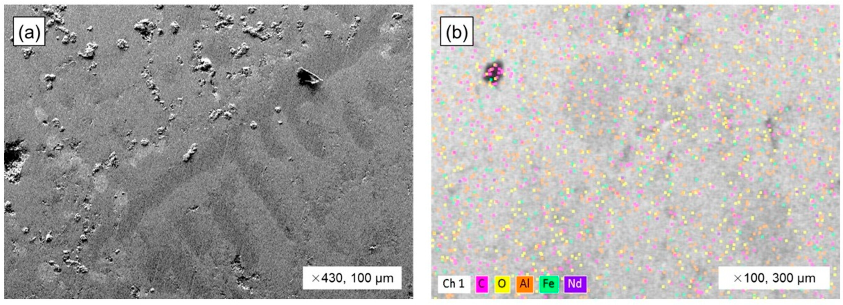
Equilibrium melting of the NdFeB magnet was conducted at 1550 °C in an argon atmosphere. A magnet sample, placed in an alumina (Al2O3) crucible, underwent equilibrium melting inside a vertical Kanthal tube furnace. The experiment, including a 3 h hold, was heated by a 5 °C/min rate. The magnet formed a metallic bulk upon melting at equilibrium. Figure 3 shows the results of the SEM–EDS analysis of the melted magnet metal bulk. Figure 3a shows the macrostructure image of magnet metal bulk, which displays an iron matrix with numerous inclusions. EDS mapping showed significant oxidation on the magnet bulk’s surface, with Fe, Nd, and Al metal distributions visible.
Table 5 presents the elemental distribution from the EDS mapping analysis of the magnet metal bulk. While the high oxygen content, measured at 35.47%, shows oxidation in the magnet bulk, it is important to note that the primary constituent elements of the underlying metal remain Nd and Fe.
Based on the weight percentages detailed in Table 4’s calculations of the input materials as the steel, magnetic material and cast iron components were precisely measured and combined within an alumina crucible. The equilibrium melting process was conducted within a super Kanthal vertical tube furnace, maintained at 1550 °C and protected by an argon gas atmosphere. In the melting process, the metallic materials reached their melting point and completely liquefied, eventually solidifying into a metal bulk. The macrostructure of the metal bulk and SEM–EDS elemental distribution analysis are shown in Figure 4. Our previous study [29] presented the elemental distribution in the metal bulk (Figure 4a) based on EDS mapping analysis; this work offers a partial analysis of the phases. Upon examination of the SEM image of the metal bulk (Figure 4a), a significant segregation of inclusions is clearly visible in the upper region, in contrast to the lower part which displays a homogenous and uniform metal matrix. Examination of inclusions in the bulk’s upper region through EDS point analysis (Figure 4b) unveiled energy intensity data (Figure 4c) strongly suggestive of the presence of REEs, including neodymium (Nd) and cerium (Ce). Upon analysis, it was determined that the metal matrix, as shown in Figure 4d, consisted entirely of iron, the composition of which is further detailed in energy intensity peaks as shown in Figure 4e. The observation of equilibrium melting at a temperature of 1550 °C within an argon atmosphere confirmed the complete melting of steel, cast iron, and magnetic materials, resulting in a homogeneous metal bulk, with the REEs present as inclusions concentrated primarily in the upper region of the bulk.
Using the given materials and experimental conditions, a smelting test was conducted in an induction furnace under an argon atmosphere. The experimental setup can be seen in Figure 2. A metal bulk formed during the induction furnace smelting test at 1550 °C, matching the prior Kantal furnace result. Figure 5 shows the results of a macrostructural analysis of the metal bulk, which revealed a lack of distinct inclusion segregation in the bulk’s upper region. There is a direct correlation between this observation and the mixing action that is inherent to the stirring of an induction furnace. Figure 5a,b show the iron-based metal bulk and its elemental composition (C, Al, Si). Analysis of the elemental composition of the RexOy inclusions found within the iron-based metal bulk (Figure 5c,d) revealed a predominance of Nd and Fe oxide compounds, suggesting their primary constituent components. The induction furnace’s magnetic field created significant stirring within the molten metal, resulting in most inclusions being transferred and corresponding on the metal’s surface, while some inclusions were kept within the liquid phase of the metal. The necessity of slag’s role in the process of collecting inclusions from the liquid metal is clearly evident, showcasing its crucial function in dissolving the inclusions and extracting the REE product.
Table 6 shows the elemental compositions of the metal matrix and inclusions as determined by EDS. The metal matrix consisted of 88.3% Fe, 4.876% C, 6.65% Si, and 0.19% Al. Upon analysis, the identified inclusions were primarily oxide products, with a composition revealing approximately 35.5% Nd and 15.2% Fe. Moreover, a mixture of oxides from impurities such as Si, Al, Mg, and Ca was found.

3.2. Thermodynamic Modeling of Steel and Magnet Smelting with Copper Slag Flux

This investigation aims to successfully separate Nd and other REEs from liquid metal by exploiting its higher oxidation potential relative to iron. The focus of this research was on the application of fayalite (2FeO·SiO2)-structured slag, derived from copper production, and its dual role as an oxidizing agent and a slag former. The presence of FeO in fayalite, acting as an oxidant, enhances the oxidation of REEs and other elements. Equation (2) is where this process is clearly outlined. In Equation (2), the standard Gibbs energy change in FeO (−295.1 kJ/mol) is considerably smaller than that of Nd2O3 at −1293.4 kJ/mol; consequently, this substantial difference creates conditions that are favorable for the reaction to proceed to the right. The calculated equilibrium constant for Equation (2), determined using the equilibrium constants of FeO (Equation (3)) and Nd2O3 (Equation (4)), exhibits a direct dependence on the partial pressure of oxygen within the reaction, which is a relationship detailed in Equation (5).
2[Nd](l) + 3(FeO)(l) = 3[Fe](l) + (Nd2O3)(s)
2 Fe ( l ) + O 2 ( g ) = 2 FeO ( s ) K F e O = a F e 2 · P O 2 a F e O at   equal   a F e = a F e O = 1 K F e O = P O 2
4 Nd ( l ) + 3 O 2 ( g ) = 2 Nd 2 O 3 ( s ) K N d 2 O 3 = ( P O 2 ) 3
K = K N d 2 O 3 ( K F e O ) 3 = 1 / ( P O 2 ) 3 ( P O 2 ) 3
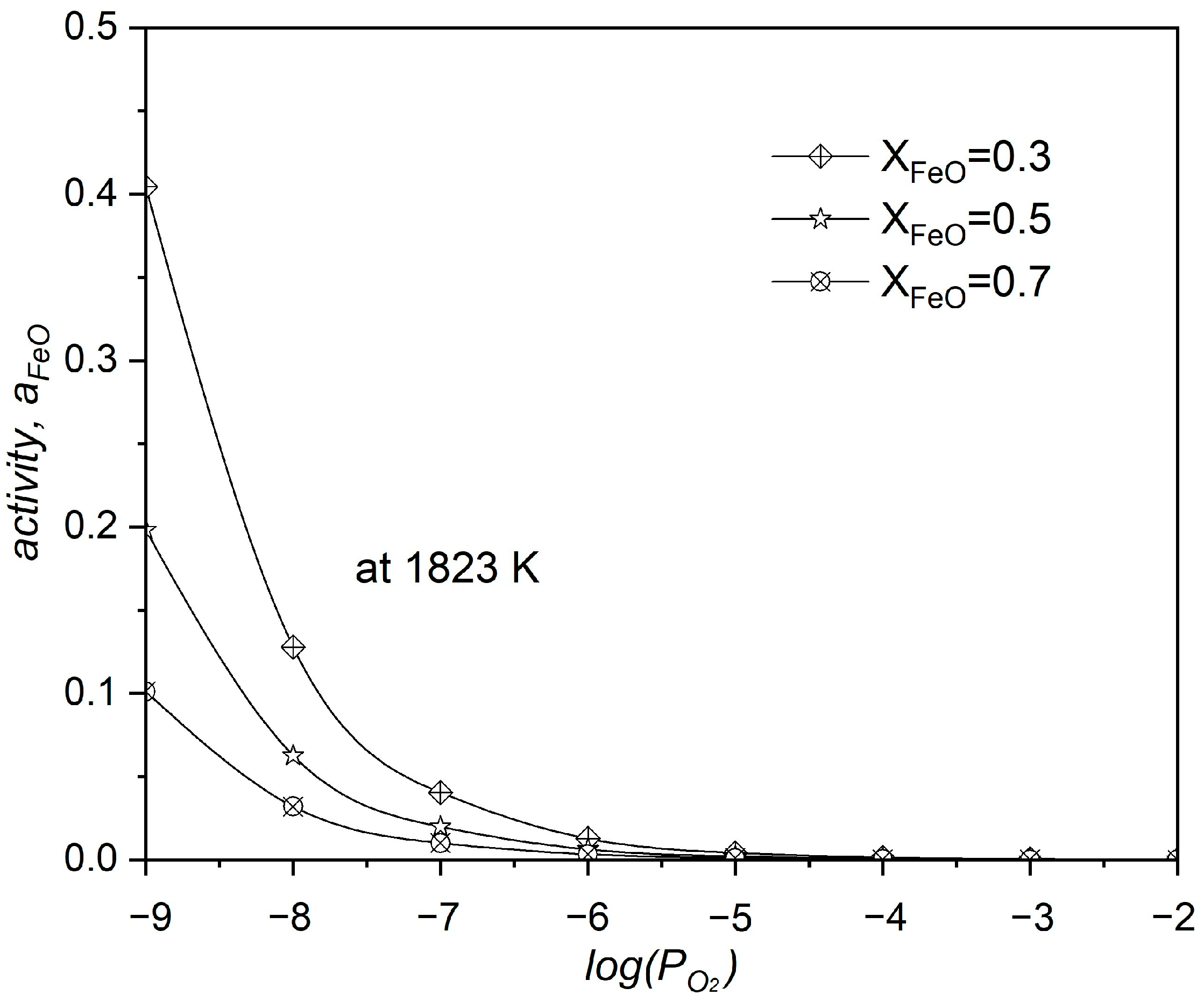
Figure 6 shows the correlation between FeO activity, its molar fraction, and oxygen partial pressure in the neodymium oxidation by FeO system. The system’s increased P O 2 correlates with decreased FeO activity ( a F e O ), which is a clear sign that the reaction produces more Nd2O3. Increasing the FeO molar fraction within the system is known to increase a F e O value.
According to thermodynamic analyses, the increased oxygen partial pressure, which was caused by FeO, ultimately resulted in an enhancement of neodymium oxidation within the liquid metal. Equation (6) shows the oxidation reaction of REEs via copper slag in form of the fayalite eutictec; this reaction’s demonstration served as the main aim of our research. In addition, FeO can also oxidize C, Si, and Mn in the liquid metal; this occurs at the same time as the oxidation of REEs, as shown in Equations (7) and (8).
a[Re](l) + bFe2SiO4(s) = c(RexOy)(s) + d(SiO2)(l) + h[Fe](l)
a[C](l) + bFe2SiO4(s) = c(CO)(s) + d(SiO2) + h[Fe](l)
a[Me](l) + bFe2SiO4(s) = c(MexOy)(s) + d(SiO2) + h[Fe](l)
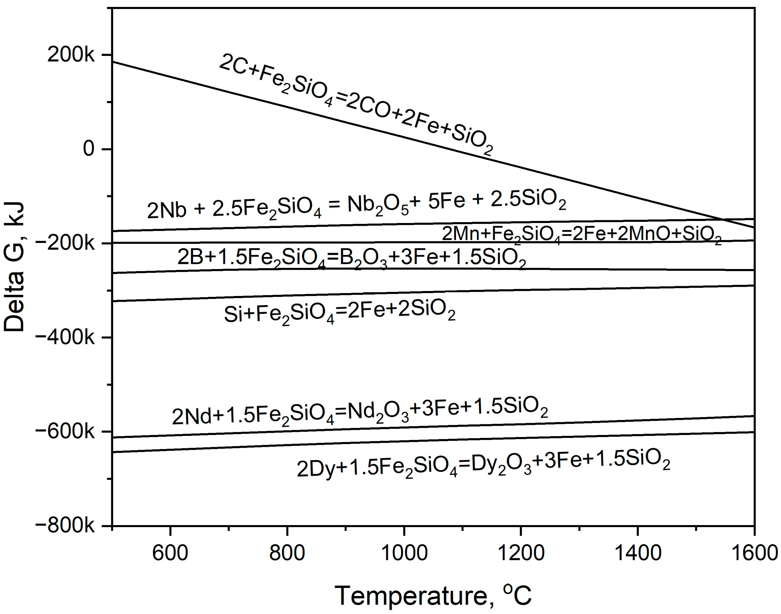
Using the FactSage 8.2 program, a thermodynamic analysis was conducted to calculate the oxidation reactions of REEs and the impurity elements within the steel in the presence of fayalite. Figure 7 shows the calculated Gibbs free energy change that results from the oxidation of elements by fayalite as a function of temperature. Upon experimental calculation, the temperature reached 1550 °C, at which point Nd and Dy achieved the most significant oxidation potential, as evidenced by Gibbs free energy changes approximating −600 kJ/mol. Among the various elements present in the steel, Si showed a strong tendency toward oxidation, as evidenced by its calculated value of approximately −300 kJ/mol, and this oxidation behavior was observed to occur concurrently with that of the REEs.
FactSage 8.2 was used to perform a thermodynamic equilibrium analysis of REE and impurity oxidation in steel with fayalite. FactSage’s Equilib mode simulated the melting of rotor steel, NdFeB magnets, and cast iron (given weight percentages) at 1550 °C, saving the resulting liquid metal and NdS solid solutions as stream solutions. To simulate smelting, solutions representing the copper slag composition (shown in Table 2) were added to the liquid steel and NdS solution at 10, 20, and 30 wt.%, respectively. This study used the copper slag flux as a variable in its calculations to determine how changes in the flux affected the liquid steel’s composition. Table 7 shows the simulation output results of FactSage Equilib. Smelting simulations at 1550 °C of rotor steel, NdFeB magnet, and cast iron yielded 99.68 g of liquid steel (1.01% C, 2.78% Si, 0.33% Mn, 4.3% S) and 0.31 g of solid NdS. Adding 10, 20, and 30 wt.% of copper slag flux to 99.68 g of liquid steel and 0.31 g of NdS solid solution at 1550 °C resulted in the completely removal of Nd and Dy, which are elements with high oxidation potential, from the liquid steel, forming Re2O3 oxide melt. With the addition of 30 wt.% slag, the B content decreased to 9 × 10⁻⁵% during this period. Reduced Nb content (0.04% to 0.03%) shows low oxidation. Si and Mn, as steel impurities, experienced significant oxidation, lowering their concentrations. C, however, showed markedly less oxidation than the others, with only 0.97% when adding 30 wt.% slag. The incorporating of copper slag resulted in a notable increase in both the weight and the purity of the liquid steel.
Table 8 shows the slag’s chemical composition from the Equilib mode simulation of rotor steel and magnet smelting with copper slag flux acting as an oxidant. The addition of 10 wt% of slag resulted in a slag FeO content of 0.54%, clearly showing that the FeO produced from fayalite decomposition was entirely used up during oxidation. A decrease in the FeO content in the slag corresponds to a proportional increase in the concentrations of both Al2O3 and MgO. The slag is primarily composed of SiO2, which constitutes 82.12% of its overall composition. The addition of 20 wt.% of slag yielded an FeO content of 1.71%, which is a finding that indicates the ongoing consumption of FeO via oxidation. However, when 30 wt.% of slag is added, the resulting slag composition reveals a 13.96% FeO content, signifying that iron oxide has concluded its role in the oxidation process.

3.3. Steel and Magnet Smelting with Copper Slag Flux

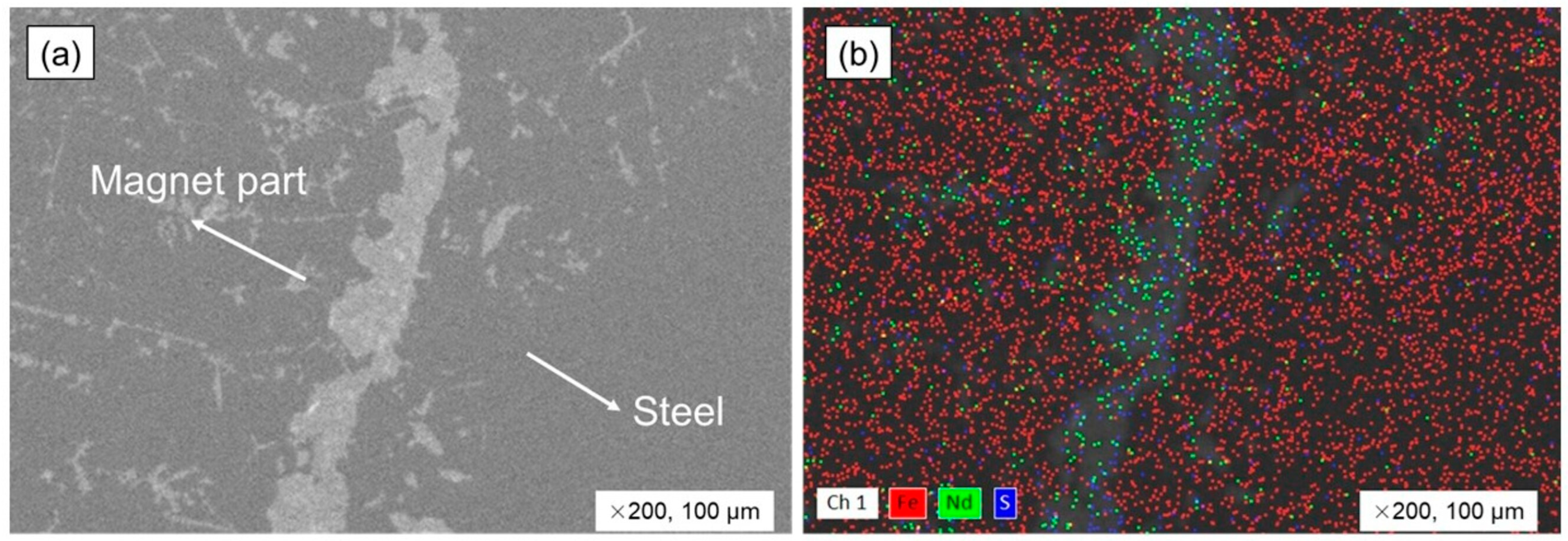
Within the scope of the study involving the selective separation of rare earth elements (REEs) from liquid metal, specifically during the smelting process combining rotor steel and NdFeB magnets, the fayalite compound (2FeO·SiO2) found in the FeO–SiO2 system was utilized for its dual functionality, serving as both an oxidant and a slag-forming agent, effectively acting as an oxygen carrier and dissolving RexOy oxides, as detailed in the previous work [29]. For this experiment, fayalite-based slag from a copper-smelting plant was used as flux in the following test. Previous tests have shown that after the metal components were completely melted, a 30 min holding period was employed using the addition of 30 wt.% of synthesized fayalite flux, resulting in a Nd recovery rate of 91%, which is an outcome which indicated the highest efficiency in the process. In this experiment, a smelting test was performed with the addition of 30 wt.% of copper slag. In an effort to diminish the diffusion of Nd into the Al2O3 crucible wall while smelting, we conducted a series of experiments that involved holding times of both 20 and 10 min, which is a reduction from the original 30 min holding time. Moreover, to make a comparison against the parameters of the experiment that were carried out before, 2 wt.% of the Fe2O3 oxidant was incorporated with the copper slag. During the 30 min and 20 min holding periods, the magnets within the molten steel were observed to have melted entirely, but it was noted that some magnetic parts did not melt during the shorter 10 min holding time. Figure 8 shows the border of the un-melted magnetic parts in the steel bulk, as seen by SEM-EDS. Non-metallic inclusions, which presented in a white color, were observed separating the steel and magnetic elements, with the steel bulk appearing as a uniform solid, whereas a large number of white inclusions were found within the magnetic part, as shown in Figure 8a. The element distribution is shown in Figure 8b using EDS mapping analysis. The white area between steel and the magnetic parts showed high Nd and S distributions. Other white, non-metallic inclusions also had high Nd distribution. The white inclusions allowed us to see how Nd started to dissolve, which was clear by their position and alignment. Because of the Nd-S-enriched boundary zone, the magnet parts in liquid steel needed time to fully dissolve and spread throughout the metal, and they do not melt and dissolve right away. EDS analysis results for element distribution are in Table 9. The distributions of 86.25% of Fe, 11.32% of Nd, and 4.62% of S were observed in the un-melted magnet part region.
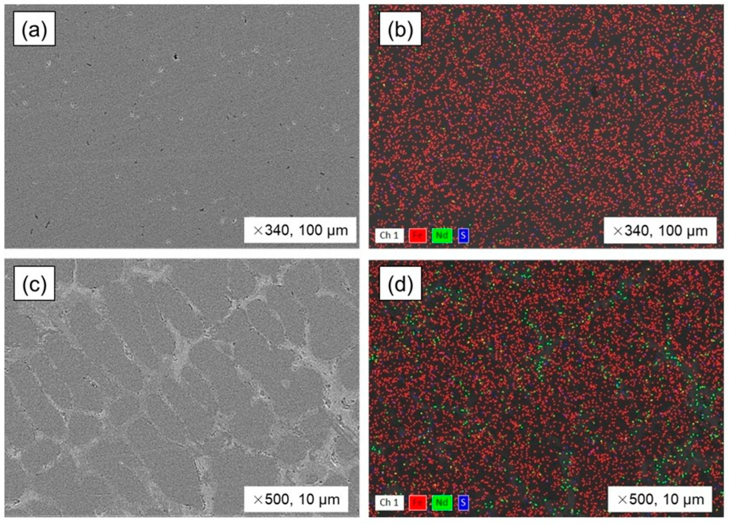
The bulk steel and un–melted magnet regions were analyzed for microstructure and elemental distribution as shown in Figure 9. The steel had a solid mass and minor porosity (Figure 9a,b). According to the EDS mapping analysis in Table 10, the steel bulk contains 1.35% of Nd and 0.11% of S. On the other hand, the un-melted magnet region presented a metallic structure that had white inclusions, which can be seen in Figure 9c,d. As shown in Table 10, the inclusions that were formed at the grain boundaries of the metal displayed a high concentration of Nd, with a distribution of 9.95%, and the inclusions also had a sulfur content of 0.21%.
Table 11 provides the results of OES analysis, showing the composition of the steel formed during smelting with 30 wt.% of copper slag added, for holding times of 30, 20, and 10 min. ICP-OES analysis accurately measured the Nd content in the steel. In addition, the findings of smelting experiments using 30 wt.% of copper slag and 2 wt.% of Fe2O3, with 30 and 20 min holding times, were evaluated through comparative analysis. Comparing the outcomes of this experiment to those of a prior smelting test employing synthesized fayalite flux, the results of the previous test [29], which are labeled as Ref, were also taken into consideration. Experiments that involved the use of copper slag and addition of Fe2O3 were designated with labels ranging from CS-01 through CS-05. The steel created by smelting with copper slag had 0.9% of carbon, but silicon varied. Copper, reduced from the slag, dissolved into the steel and appeared at about 0.4%. All samples showed very low Nd content, suggesting that the magnetic components were fully removed from the liquid steel during smelting using the oxidant agent.
According to Figure 10, a graph shows a comparison between the primary impurities and the grade of Fe present in the steel that was formed during the experiments, and this is in relation to the Ref. results obtained from the previous experiment. The carbon content in the steel produced in the Ref. experiment was measured at 1.08%, while the steel produced during this experiment with the use of copper slag had an average carbon content of 0.9%, thus being 0.1% less. This indicates that the copper slag’s impurities may have been more involved in iron reduction. The copper content found to be dissolved in the steel samples from this particular experiment varied from 0.3% to 0.4%, as a specific example. Although the Si content of the steel showed some inconsistency, it was found to be considerably greater than the reference value across all observed instances. The Fe grade in the steel during this experiment was found to be a maximum of 97.0%, which was a lower value when compared to the Ref. results.
As shown in Table 12, the composition of the slag formed during experimental smelting is compared to the composition of the Ref slag. The slag is mainly composed of FeO, SiO2, and Al2O3 oxides, with MnO, CaO, MgO, and other impurity oxides. There were no considerable differences in the impurity oxides found in the slags. CuO, ZnO, NiO, MoO3, and PbO were not found in copper slag, pointing to metal reduction and gaseous transfer. The presence of the elements in the steel composition, as shown in Table 11, verifies this. In the Ref. slag, SiO2 measured 52.6%, whereas the slags produced during this experiment showed a range of SiO2 content, varying from 43% to 48%. The Al2O3 oxide concentration is approximately twice greater than what is observed in the Ref. slag. During the holding time experiments, the Fe2O3 content measured at 10 min showed results of 15% and 16%, whereas the durations of 20 and 30 min presented a range between 24% and 26%. The surface of molten steel may experience increased iron oxidation with longer holding times. The Nd content in the slag was measured precisely with ICP-OES. The Ref. slag was found to contain 4 wt.% of Nd, while the other slags exhibited a relatively low range of Nd content, specifically between 2.1 wt.% and 2.9 wt.%. During a 10 min holding time, the Nd content in the slag was at its lowest, measuring 0.96%, which is caused by the fact that the molten metal retained the mass of the magnet.
The Fe recovery level from copper slag, which is found in the Fe–SiO2 system, was the subject of an evaluation. The presence of FeO, serving as an oxygen carrier for elements, has a higher oxidation potential, which caused a reduction in Fe, allowing for its transfer to molten steel, which subsequently improved the overall steel yield. In addition to the other advantages, taking iron from magnetic and copper slags raises the level of economic value. In Figure 11, a graph is presented to compare Fe recovery when using additional oxidant and slag-forming materials, as well as the corresponding mass balance calculation data. It has been observed that the recovery of iron from slag during smelting with copper slag could potentially surpass 50% with prolonged holding times, and theoretical assessments propose that the extraction of iron could achieve up to 70% when smelting with copper slag and Fe2O3 additives.

3.4. The Neodymium Recovery Within the Slag

A thorough analysis and calculation were performed to determine the efficiency of extracting REEs from waste electric vehicle motors using copper slag, with a particular emphasis on Nd, which is an important element. The method described in Equation (1) was employed to calculate the degree of Nd recovery, which was determined by contrasting the amount of Nd input with magnet material with the amount that was output via slag. Nd mass balance data from this experiment is shown in Table 13. While the weight of slag formed during smelting experiments reveals a similar weight, the slag yield drops to 74.53 g when exposed to short-term holding conditions of 10 min. This observation is connected to the reduced iron oxide content that was revealed by the chemical composition analysis of the slag, the results of which are shown in Table 12. As copper slag is introduced into molten steel initially, Fe reduction from the slag proceeds at an intense rate, which results in transferring Fe into the metal phase. Following a period, the oxidation of Fe will start again, resulting in the Fe returning to the slag phase.
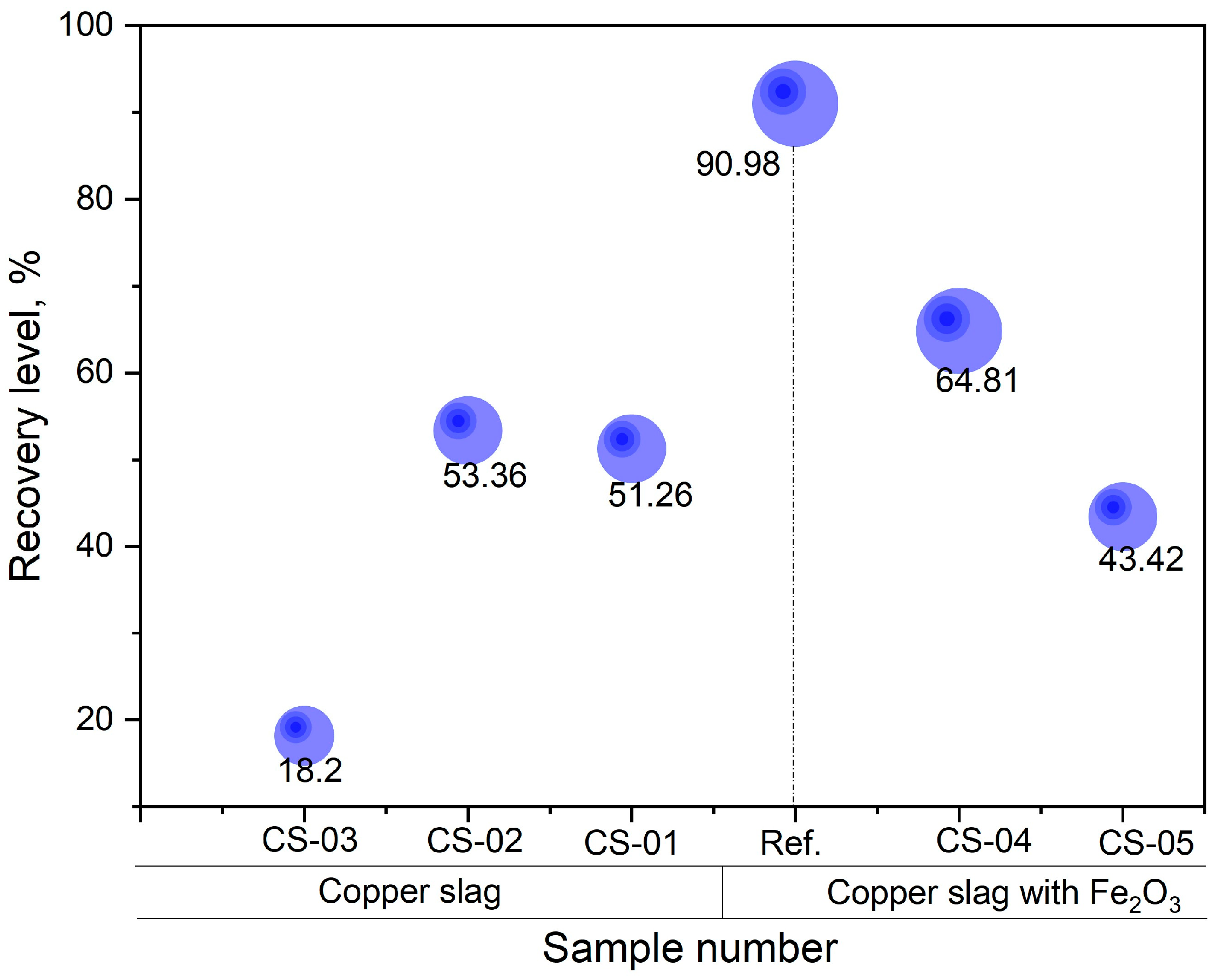
Nd recovery rates are compared in Figure 12. This evaluates the efficiency of Nd extraction from molten steel using copper slag, based on smelting holding time. With Ref. synthetic fayalite slag in the previous test, 90.98% of the Nd was extracted from the molten metal when 30 wt.% of fayalite flux and 2 wt.% of Fe2O3 were added for 30 min. While the smelting process was underway, observations revealed that when the holding time was just 10 min, the magnetic fraction did not completely melt; instead, it was present in the metal. When holding times are longer than 20 min, the magnet parts completely melt, which leads to an improved extraction of Nd. This is clearly illustrated by the recovery level: 18.2% for the CS-03 sample (10 min), and 53% and 51% for the CS-02 and CS-01 samples in that order. By adding Fe2O3 as an extra oxygen carrier prior to smelting, the recovery level increased (CS-4), ultimately reaching a value of 64.81%. With this experiment, the use of copper slag for Nd extraction reached a peak extraction degree of approximately 65%, which seems considerably less than the findings from prior experiments where modeled synthetic fayalite flux was used.

4. Discussion

Table 14 shows a comparative analysis of several studies focusing on techniques for extracting REEs from NdFeB magnets using pyrometallurgical methods and detailing the characteristics of the process employed in each study. In Bowen et al.’s [39] study, a mixture of NdFeB magnet powder and pyrolyzed sawdust underwent carbonization and hydrogenation at 1400 °C, followed by REE oxidation (in deionized water) and magnetic iron removal. The experimental results of Aarti et al. [40], Masahiro et al. [41], and Yuuki et al. [42] showed the advantage of lower-temperature REE production via oxidation and separation as RexOy after chlorination roasting with different chloritizing agents. Extraction of REEs at roughly 1000 °C is possible, studies show, via the formation of ReCl2 and ReF3 from NdFeB magnets in molten salts (e.g., MeCl2 and MeF3) [43,44,45,46]. Research also investigated REE extraction through inter-metallic formation using molten metals (Mg, Ag, Cu, Pr alloys) [47,48,49,50] and NdFeB magnet powder; dissolved REEs in metal, for instance, separate as RexOy due to REEs’ strength oxidation potential. Another area of research involves melting NdFeB magnets, extracting REEs via RexOy formation based on oxidation potential, and subsequently dissolving the RexOy in various slag systems. The smelting process involving slag has led to extensive study [51,52] of glass slag systems based on B2O3, which contains boron—a crucial element in magnets—and also into metallurgical CaO–Al2O3 slag systems [53]. Our work [29] innovatively used copper slag’s fayalite flux (2FeO·SiO2) within the FeO–SiO2 slag system. The focus of most studies has been the recycling of NdFeB magnet scrap; however, a different strategy is employed in the research of Katsunori et al. [34] and in our work [29], where we melt NdFeB magnets and EV motor steel together, resulting in the oxidation of rare earth elements within the liquid steel, which allows for their selective extraction via dissolution within slag, which is a significant distinguishing characteristic of this technique. This technology’s advantage lies in its direct applicability to the future recycling of EV motors, making it a valuable asset for sustainable practices.
The intention was to illustrate the economic gains derived from recycling waste EV motor, evaluating the process through its material and energy use, in addition to the quantity of products generated. Based on the material composition of the EV-80 kW NE–MP synchronous motor, which was previously discussed in our research [29], we calculated the yields of Al, Cu, REEs, and Fe-C alloys extracted from one motor and displayed them in Table 15. Within the input column, the materials that enter from one EV motor are shown, along with the energy consumption, which is calculated based on the weights of the alloys, needed to melt the Al, Cu, and Fe alloys. The EV motor is composed of the following materials: 37.8 kg of steel and cast iron, 8.5 kg of copper wire, 14.1 kg of aluminum for the housing, and 2.1 kg of NdFeB magnetic components. Displayed separately in the final stage of the separation process are the amounts of cast iron to be used as a carburizer in the melting process of steel and magnets, in addition to the amount of oxygen carrier Fe2O3 and copper slag that were added. Taking into consideration their respective weights, a calculation was made to approximate the energy necessary to melt aluminum, copper, and steel, and the estimated total electrical energy consumption for recycling EV motors throughout the entire process was roughly 44 kWh. Based on the recovery rates of 95% for aluminum, 98% for copper, and 91% for REEs, while also accounting for the losses that occur due to aluminum oxidation during the melting stage, the potential to recover materials from one EV-80 kW NE–MP synchronous motor is present, with the possibility of yielding 8.33 kg of copper, 13.40 kg of aluminum alloy, and 0.57 kg of REEs. Considering the incoming amounts from metal materials and additives including copper slag flux and Fe2O3, one EV motor’s smelting process makes it possible to generate 55.77 kg of Fe–C alloy. This 11.56 kg quantity of slag, which holds REEs, is slated for use as the initial substance in the recovery and leaching procedures designed to extract the REEs.
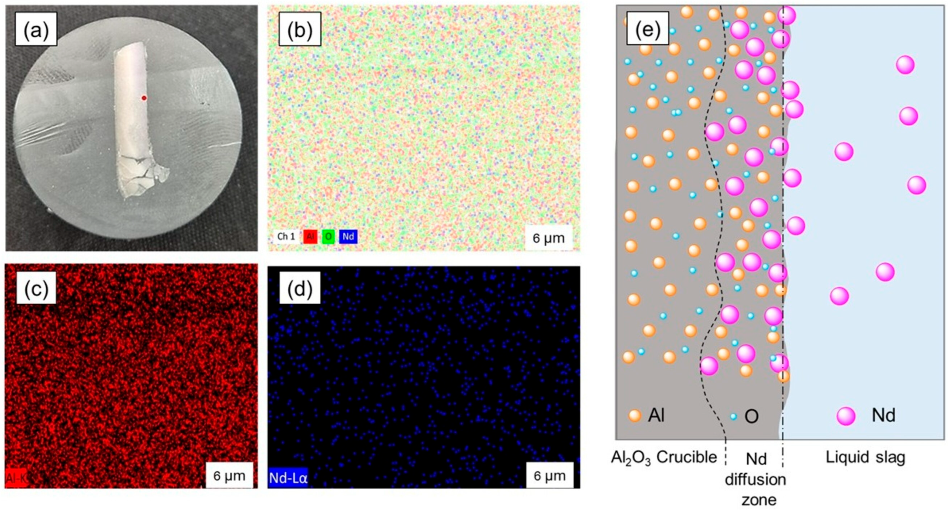
High-temperature experiments (at 1550 °C) investigated how fayalite flux and copper slag additions impact REE oxidation and slag formation during EV motor steel and NdFeB magnet smelting. When we look at the previous work [29], the addition of 30 wt.% of synthetized fayalite flux led to the best Nd recovery rate, which was as high as 91%. Repeated experiments yielded no better results. The recovery level achieved in this experiment peaked at approximately 65%, which was the highest result. Slag diffusion was observed in the Al2O3 crucible’s slag zone, but not in its metal zone. Figure 13 shows the analysis of the diffusion zone in the aluminum crucible-interacting segment with slag and a schematic explanation of Nd diffusion into the crucible wall. As shown in Figure 13a, the slag diffused into the Al2O3 crucible wall so much that nearly half of the wall’s thickness was affected by this Nd diffusion process. Figure 13b shows the SEM–EDS mapping analysis of Al, Nd, and O element distribution within the Al2O3 crucible wall’s slag diffusion zone. Upon examination of the distribution analysis of Al and Nd, as shown in Figure 13c,d, it became apparent that substantial Nd diffusion had occurred, with the resulting diffusion zone exhibiting a characteristic pink color indicative of Nd2O3 oxide. FactSage’s FToxid data suggests the possibility of Al and Nd oxide compounds such as Al2Nd4O9, Al5Nd2O12, and AlNdO3. The mechanism of Nd diffusion into the Al2O3 crucible wall is explained by the schematic shown in Figure 13e. The oxidation of Nd caused its separation from the liquid metal, resulting in Nd2O3 which the slag transported to the crucible wall. Upon contact at a high temperature of 1550 °C, a reaction occurs between Al2O3 and Nd2O3 oxides, which leads to Nd adhering to the crucible wall and then diffusing further into the crucible. During smelting experiments using synthetic fayalite flux, the slag exhibited SiO2 content surpassing 50%, which is a result that can be explained by the significant activity of S i O 4 4 anions interacting with AlNdO3. In addition to interacting with AlNdO3, the S i O 4 4 anions also cause substantial erosion of the Al2O3 crucible wall. The Ref. slag’s composition, which contains 13.6% of Al2O3, is what confirms this. Experiments that use copper slag, which is composed of 4.81% of Al2O3 and basic oxides such as MgO, CaO, and K2O, exhibit a decreased ability to dissolve Nd that has adhered to or diffused into the crucible wall when contrasted in this work; this accounts for the differences that have been observed. We conducted smelting experiments at 1550 °C using MgO and SiC crucibles. Intense heat led to cracked crucibles, thus limiting the number of experimental runs we could perform. Nd diffusion observed within the Al2O3 crucible, as revealed by our research, introduces a considerable complication into the calculation of Nd recovery based on its concentration in the slag. The analysis of the Nd content within the metal sample, which is detected at 0.08%, definitively confirmed the complete extraction of all REEs from the liquid metal. Considering the practicalities of industrial smelting, furnaces must use an acidic SiO2-based lining; this is revealed by the use of fayalite slag flux in the processing of slag systems containing neodymium silicate. The diffusion of Nd, followed by its adhering to the wall of the furnace lining, which creates a layer, suggests that in practical smelting processes, repeated smelting cycles cause the diffusion of Nd to stop, and the Nd-rich layer that has reacted to the wall is then dissolved into the slag that is generated during subsequent smelting. Based on this, it seems likely that the extraction of Nd has the potential to increase in the practical process. Considering the design and the features of the equipment used in our experiments, a ceramic crucible was the method of choice for performing the smelting process. In accordance with the proposal, the next semi-laboratory experiment will involve the use of a furnace that features an acidic SiO2-based lining.

5. Conclusions

NdFeB permanent magnets, which are crucial for EV motors and wind turbine generators, account for over half of all rare earth element consumption. As green energy grows, discarded EV motors and turbine generators could be future REE sources. The purpose of this research is to melt together motor steel and NdFeB magnets, use the strong oxidation potential of REEs to convert them into an oxide form, and then selectively recover those oxides employing copper slag. The FeO–SiO2 system can act as both an oxygen carrier and a slag former based on S i O 4 4 for dissolving REEs. The copper slag, which had a fayalite structure and the chemical formula 2FeO·SiO2, was found to completely fulfill the requirements. Nd extraction reached nearly 91% in our previous work with synthesized fayalite flux. In this study, we used copper slag, which primarily consists of fayalite, to recover REEs. The recovery rate reached 64.81% in the smelting process when using 2 wt.% of Fe2O3 and 30 wt.% of copper slag, held for 30 min. During smelting, Nd2O3 reacted with the Al2O3 crucible, creating AlNdO3, which adhered and then diffused into the crucible wall. The observations indicated that the presence of CaO, MgO, and Al2O3 oxides in the slag, which combine with SiO2, had the consequence of reducing the slag’s capacity to dissolve the AlNdO3 compound that was adhered to the crucible wall. This leads to a eutectic compound that hinders the SiO2 in the slag from dissolving Nd that has either adhered to or diffused within the crucible wall.
As recommended in the practical process of smelting, using a furnace that is lined with SiO2 and performing a series of repeated smelting cycles might increase the degree to which Nd is extracted by stopping it from adhering to the furnace lining. Furthermore, extracting over 50% of iron from copper slag supports eco-friendly production with economic benefits. We are of the opinion that our research will provide a valuable basis on which semi-laboratory experiments can be conducted.

Author Contributions

E.U., methodology, data curation, writing—original draft, software, writing—review and editing, data curation; C.-J.K., formal analysis, software; Y.-J.C., investigation, project administration, funding acquisition; J.-P.W., project administration, conceptualization. All authors have read and agreed to the published version of the manuscript.

Funding

This research, supported by the Brain Pool program (Grant Number RS-2023-00222959), receives funding from the Ministry of Science and ICT through the National Research Foundation of Korea. Additionally, it benefits from support provided by the Hyundai Motor Group.

Data Availability Statement

The original contributions presented in the study are included in the article, and further inquiries can be directed to the corresponding author.

Conflicts of Interest

Authors E.U., C.-J.K., and J.-P.W. have no other conflicts of interest related to this research. Author Y.-J.C. is employed by Hyundai Motor Co. The remaining authors declare that the research was conducted in the absence of any commercial or financial relationships that could be construed as a potential conflict of interest.

References

  1. Balaram, V. Rare earth elements: A review of applications, occurrence, exploration, analysis, recycling, and environmental impact. Geosci. Front. 2019, 10, 1285–1303. [Google Scholar] [CrossRef]
  2. Emmanuel, O.O.; Ethan, S.; Amin, M. A comparative state-of-technology review and future directions for rare earth element separation. Renew. Sustain. Energy Rev. 2021, 143, 110917. [Google Scholar] [CrossRef]
  3. Leal Filho, W.; Kotter, R.; Özuyar, P.G.; Abubakar, I.R.; Eustachio, J.H.P.P.; Matandirotya, N.R. Understanding Rare Earth Elements as Critical Raw Materials. Sustainability 2023, 15, 1919. [Google Scholar] [CrossRef]
  4. Wei, C.-W.; Deng, M.; Xu, C.; Chakhmouradian, A.R.; Smith, M.P.; Kynicky, J.; Song, W.-L.; Chen, W.; Fu, B. Mineralization of the Bayan Obo Rare Earth Element Deposit by Recrystallization and Decarbonation. Econ. Geol. 2022, 117, 1327–1338. [Google Scholar] [CrossRef]
  5. Michael, A.; Broom-Fendley, S.; Wei, C. Formation of Rare Earth Deposits in Carbonatites. Elements 2021, 17, 327–332. [Google Scholar] [CrossRef]
  6. Wei, C.-W.; Xu, C.; Deng, M.; Song, W.-L.; Shi, A.; Li, Z.; Fan, C.; Kuang, G. Origin of metasomatic fluids in the Bayan Obo rare-earth-element deposit. Ore Geo. Rev. 2022, 141, 104654. [Google Scholar] [CrossRef]
  7. Imarc. Rare Earth Elements Market Size, Share, Trends and Forecast by Application and Region, 2025–2033. Available online: https://www.imarcgroup.com/rare-earth-industry (accessed on 11 February 2025).
  8. Markets & Markets. Rare Earth Metals Market by Type (Lanthanum Oxide, Cerium Oxide, Neodymium Oxide, Europium Oxide, Terbium Oxide), Application (Permanent Magnets, Catalysts, Glass Polishing, Phosphors, Metal Alloys, Ceramics), and Region-Global Forecast to 2030. Available online: https://www.marketsandmarkets.com/Market-Reports/rare-earth-metals-market-121495310.html?gad_source=1&gad_campaignid=365563516&gbraid=0AAAAADxY7SynAn4UULwIuMmlhJq11KBcF&gclid=Cj0KCQjwuKnGBhD5ARIsAD19RsZpwhpjdNDO7YwNJnw1nceIGmqr-QMRwtUdxWKszS6w8-pd9BOnzwwaAuzkEALw_wcB (accessed on 1 July 2025).
  9. Statista. Rare Earth Mining Global Distribution 2024, by Country. Available online: https://www.statista.com/statistics/270277/mining-of-rare-earths-by-country/ (accessed on 25 February 2025).
  10. Nasdag. Top 10 Countries by Rare Earth Metal Production. Available online: https://www.nasdaq.com/articles/top-10-countries-rare-earth-metal-production (accessed on 1 March 2025).
  11. Ilankoon, I.M.S.K.; Dushyantha, N.P.; Mancheri, N.; Edirisinghe, P.M.; Neethling, S.J.; Ratnayake, N.P.; Rohitha, L.P.S.; Dissanayake, D.M.D.O.K.; Premasiri, H.M.R.; Abeysinghe, A.M.K.B.; et al. Constraints to rare earth elements supply diversification: Evidence from an industry survey. J. Clean. Prod. 2022, 331, 129932. [Google Scholar] [CrossRef]
  12. Mpila, M.N.; Randy, L.V.W. Rare earth elements: Sector allocations and supply chain considerations. J. Rare Earths 2025, 43, 1–8. [Google Scholar] [CrossRef]
  13. INN. Rare Earths Market Update: H1 2025 in Review. Available online: https://investingnews.com/rare-earths-forecast/ (accessed on 14 August 2025).
  14. Orlova, S.; Rassõlkin, A. Permanent Magnets in Sustainable Energy: Comparative Life Cycle Analysis. Energies 2024, 17, 6384. [Google Scholar] [CrossRef]
  15. Usman, A.; Saxena, A. Technical Roadmaps of Electric Motor Technology for Next Generation Electric Vehicles. Machines 2025, 13, 156. [Google Scholar] [CrossRef]
  16. Ranjan, P.; Kalla, U.K. Comprehensive Study on Various Types of Magnets Used in Permanent Magnet Electrical Motors. In Proceedings of the 2024 IEEE Region 10 Symposium (TENSYMP), New Delhi, India, 27–29 September 2024; pp. 1–7. [Google Scholar] [CrossRef]
  17. KtM. The Role of Sintered NdFeB Magnets in Electric Vehicles. Available online: https://www.ktmagnet.com/the-role-of-sintered-ndfeb-magnets-in-electric-vehicles.html (accessed on 31 January 2024).
  18. Heim, J.W.; Vander Wal, R.L. NdFeB Permanent Magnet Uses, Projected Growth Rates and Nd Plus Dy Demands across End-Use Sectors through 2050: A Review. Minerals 2023, 13, 1274. [Google Scholar] [CrossRef]
  19. Wang, H.; Lamichhane, T.N.; Paranthaman, M.P. Review of additive manufacturing of permanent magnets for electrical machines: A prospective on wind turbine. Mater. Today Phys. 2022, 24, 100675. [Google Scholar] [CrossRef]
  20. Stanford Magnets. Application of Neodymium Magnets in Wind Turbine Generators. Available online: https://www.stanfordmagnets.com/application-of-neodymium-magnets-in-wind-turbine-generators.html#:~:text=The%20Curie%20temperature%20of%20the,dimensional%20tolerances%20and%20magnetic%20properties (accessed on 16 April 2024).
  21. Divyani, J.; Sunil, K.; Shally, V. Introduction to artificial intelligence-empowered electric vehicles in smart grids. In Artificial Intelligence-Empowered Modern Electric Vehicles in Smart Grid Systems; Aparna, K., Sudeep, T., Eds.; Elsevier: Amsterdam, The Netherlands, 2024; pp. 3–31. [Google Scholar] [CrossRef]
  22. Arévalo, P.; Ochoa-Correa, D.; Villa-Ávila, E. A Systematic Review on the Integration of Artificial Intelligence into Energy Management Systems for Electric Vehicles: Recent Advances and Future Perspectives. World Electr. Veh. J. 2024, 15, 364. [Google Scholar] [CrossRef]
  23. Evs & Beyond. 2024 Breaks Global EV Sales Record with over 17 Million Units Sold. Available online: https://evsandbeyond.co.nz/2024-breaks-global-ev-sales-record-with-over-17-million-units-sold/#:~:text=Electric%20vehicle%20(EV)%20sales%20reached,1.3%20million%20(+27%25) (accessed on 16 January 2025).
  24. RHO Motion. Over 17 Million EVs Sold in 2024—Record Year. Available online: https://rhomotion.com/news/over-17-million-evs-sold-in-2024-record-year/#:~:text=Over%2017%20million%20EVs%20sold%20in%202024,*%20Rest%20of%20World:%201.3%20million%2C%20+27% (accessed on 14 January 2025).
  25. Mohamed, K.; Nassar, Y.; El-Khozondar, H.J.; Monaem, E.R.Z.; Yaghoubi, E.; Yaghoubi, E. Electric Vehicles in China, Europe, and the United States: Current Trend and Market Comparison. Int. J. Electr. Eng. Sustain. 2024, 2, 1–20. Available online: https://ijees.org/index.php/ijees/article/view/70/36. (accessed on 9 January 2024).
  26. IEA.org. The Global Electric Vehicle Fleet Is Set to Grow Twelve-Fold by 2035 Under Stated Policies. Available online: https://www.iea.org/reports/global-ev-outlook-2024/outlook-for-electric-mobility (accessed on 23 April 2024).
  27. Danouche, M.; Bounaga, A.; Oulkhir, A.; Boulif, R.; Zeroual, Y.; Benhida, R.; Lyamlouli, K. Advances in bio/chemical approaches for sustainable recycling and recovery of rare earth elements from secondary resources. Sci. Total Environ. 2024, 912, 168811. [Google Scholar] [CrossRef]
  28. Cherkezova-Zheleva, Z.; Burada, M.; Sobetkii, A.E.; Paneva, D.; Fironda, S.A.; Piticescu, R.R. Green and Sustainable Rare Earth Element Recycling and Reuse from End-of-Life Permanent Magnets. Metals 2024, 14, 658. [Google Scholar] [CrossRef]
  29. Urtnasan, E.; Park, J.-H.; Chung, Y.-J.; Wang, J.-P. Pyrometallurgical Recycling of Electric Motors for Sustainability in End-of-Life Vehicle Metal Separation Planning. Processes 2025, 13, 1729. [Google Scholar] [CrossRef]
  30. Li, Z.; Hamidi, A.S.; Yan, Z.; Sattar, A.; Hazra, S.; Soulard, J.; Guest, C.; Ahmed, S.H.; Tailor, F. A circular economy approach for recycling Electric Motors in the end-of-life Vehicles: A literature review. Resour. Conserv. Recycl. 2024, 205, 107582. [Google Scholar] [CrossRef]
  31. Tiwari, D.; Miscandlon, J.; Tiwari, A.; Jewell, G.W. A Review of Circular Economy Research for Electric Motors and the Role of Industry 4.0 Technologies. Sustainability 2021, 13, 9668. [Google Scholar] [CrossRef]
  32. Chang, M.M.L.; Ong, S.K.; Nee, A.Y.C. Approaches and Challenges in Product Disassembly Planning for Sustainability. Procedia Cirp 2017, 60, 506–511. [Google Scholar] [CrossRef]
  33. Mitrouchev, P.; Wang, C.G.; Lu, L.X.; Li, G.O. Selective disassembly sequence generation based on lowest level disassembly graph method. Int. J. Adv. Manuf. Technol. 2015, 80, 141–159. [Google Scholar] [CrossRef]
  34. Katsunori, Y. Rare Earth Element Recovery Technology for Motor Magnets for Electric Vehicles That Aims to Reduce Costs in a Short Time. Science Technology Innovation Japan. Available online: https://sj.jst.go.jp/stories/2022/s0301-01a.html (accessed on 1 March 2022).
  35. Saito, T.; Sato, H.; Ozawa, S.; Yu, J.; Motegi, T. The extraction of Nd from waste Nd–Fe–B alloys by the glass slag method. J. Alloys Compd. 2003, 353, 189–193. [Google Scholar] [CrossRef]
  36. Yang, Y.; Abrahami, S.T.; Xiao, Y. Recovery of rare earth elements from EOL permanent magnets with molten slag extraction. In The 3rd International Slag Valorisation Symposium; ACCO: Leuven, Belgium, 2013; pp. 249–252. [Google Scholar]
  37. Kim, K.O.; Jung, Y.H.; Park, J.C.; Lim, M.S. Comparative Study of Mechanical and Electrical Characteristics of High-Strength and Conventional Electrical Steel for EV Traction High-Speed Multilayer IPMSM Using Rare-Earth Free PM. IEEE Trans. Magn. 2023, 59, 8102205. [Google Scholar] [CrossRef]
  38. Lobo, J.A.; Geiger, G.H. Thermodynamics and solubility of carbon in ferrite and ferritic Fe-Mo alloys. Metall. Trans. A 1976, 7, 1347–1357. [Google Scholar] [CrossRef]
  39. Liu, B.; Zhu, N.; Li, Y.; Wu, P.; Dang, Z.; Ke, Y. Efficient recovery of rare earth elements from discarded NdFeB magnets. Process Saf. Environ. Prot. 2019, 124, 317–325. [Google Scholar] [CrossRef]
  40. Aarti, K.; Raman, R.; Randhawa, N.S.; Sushanta, K.S. Energy efficient process for recovery of rare earths from spent NdFeB magnet by chlorination roasting and water leaching. Hydrometallurgy 2021, 201, 105581. [Google Scholar] [CrossRef]
  41. Masahiro, I.; Koji, M.; Ken-ichi, M. Novel rare earth recovery process on NdFeB magnet scrap by selective chlorination using NH4Cl. J. Alloys Compd. 2009, 477, 484–487. [Google Scholar] [CrossRef]
  42. Yuuki, M.; Naoto, T.; Katsuyasu, S. Selective Recovery of Rare Earth Elements from Dy containing NdFeB Magnets by Chlorination. ACS Sustain. Chem. Eng. 2013, 1, 655–662. [Google Scholar] [CrossRef]
  43. Shirayama, S.; Okabe, T.H. Selective Extraction and Recovery of Nd and Dy from Nd-Fe-B Magnet Scrap by Utilizing Molten MgCl2. Met. Mater. Trans. B 2018, 49, 1067–1077. [Google Scholar] [CrossRef]
  44. Tomohiko, A.; Yu, M.; Tomonori, S.; Masahide, O.; Toru, H.O. Optimum conditions for extracting rare earth metals from waste magnets by using molten magnesium. J. Alloys Compd. 2017, 703, 337–343. [Google Scholar] [CrossRef]
  45. Hua, Z.; Wang, J.; Wang, L.; Zhao, Z.; Li, X.; Xiao, Y.; Yang, Y. Selective Extraction of Rare Earth Elements from NdFeB Scrap by Molten Chlorides. ACS Sustain. Chem. Eng. 2014, 2, 2536–2543. [Google Scholar] [CrossRef]
  46. Abbasalizadeh, A.; Malfliet, A.; Seetharaman, S.; Sietsma, J.; Yang, Y.X. Electrochemical Recovery of Rare Earth Elements from Magnets: Conversion of Rare Earth Based Metals into Rare Earth Fluorides in Molten Salts. Mater. Trans. 2017, 58, 400–405. [Google Scholar] [CrossRef]
  47. Sun, M.; Hu, X.; Peng, L.; Fu, P.; Ding, W.; Peng, Y. On the production of Mg-Nd master alloy from NdFeB magnet scraps. J. Mater. Process. Technol. 2015, 218, 57–61. [Google Scholar] [CrossRef]
  48. Takeda, O.; Okabe, T.H.; Umetsu, Y. Phase equilibrium of the system Ag–Fe–Nd, and Nd extraction from magnet scraps using molten silver. J. Alloys Compd. 2004, 379, 305–313. [Google Scholar] [CrossRef]
  49. Martina, M.; Annett, G.; Mihai, S.; Margitta, U.; Wolfgang, L. A route for recycling Nd from Nd-Fe-B magnets using Cu melts. J. Alloys Compd. 2015, 647, 997–1006. [Google Scholar] [CrossRef]
  50. Ching-Chien, H.; Chih-Chieh, M. Vacuum processing temperature effect on highly coercive recycled NdFeB permanent magnets with Pr-based alloy addition. Mater. Chem. Phys. 2024, 325, 129648. [Google Scholar] [CrossRef]
  51. Bian, Y.; Guo, S.; Jiang, L. Extraction of Rare Earth Elements from Permanent Magnet Scraps by FeO–B2O3 Flux Treatment. J. Sustain. Metall. 2015, 1, 151–160. [Google Scholar] [CrossRef]
  52. Chung, H.; Stopic, S.; Emil-Kaya, E.; Gürmen, S.; Friedrich, B. Recovery of Rare Earth Elements from Spent NdFeB-Magnets: Separation of Iron through Reductive Smelting of the Oxidized Material (Second Part). Metals 2022, 12, 1615. [Google Scholar] [CrossRef]
  53. Blenau, L.W.; Vogt, D.; Lonski, O.; Abrar, A.; Fabrichnaya, O.; Charitos, A. Development of a Process to Recycle NdFeB Permanent Magnets Based on the CaO-Al2O3-Nd2O3 Slag System. Processes 2023, 11, 1783. [Google Scholar] [CrossRef]
Scheme 1. Using the different melting points of metals at each temperature, the metallic components of EV motors are separated. Copper slag, composed of the fayalite compound 2FeO·SiO2, uses FeO as an oxidant and SiO2 as the base for its formation. The strong bond between RexOy oxides and the S i O 4 4 slag base produces nRexO·SiOy silicates that are dissolved by the slag. The slag containing RexOy serves as a raw material for extracting REEs.
Processes 13 03502 sch001
Figure 1. The XRD pattern of synthetic fayalite flux.
Processes 13 03502 g001
Figure 2. Schematic diagram of the experimental apparatus.
Processes 13 03502 g002
Figure 3. SEM–EDS analysis of NdFeB magnet in equilibrium melting. (a) SEM image of magnet metal bulk and (b) EDS mapping image of magnet metal bulk.
Processes 13 03502 g003
Figure 4. SEM–EDS analysis of the metal bulk in equilibrium smelting. (a) SEM image of metal bulk (presented by Erdenebold et al. [29]); (b,d) EDS point image of inclusions and matrix in the metal bulk; (c,e) EDS X-ray pattern of inclusions and matrix.
Processes 13 03502 g004
Figure 5. SEM–EDS analysis of the metal bulk in equilibrium smelting using induction furnace. (a) SEM image of metal bulk; (b) EDS X-ray pattern of metal matrix; (c) SEM image of inclusions in the metal bulk; (d) EDS X-ray pattern of inclusions.
Processes 13 03502 g005
Figure 6. FeO activity on oxygen partial pressure ( P O 2 ) during neodymium oxidation at 1550 °C by FeO (presented by Erdenebold et al. [29]).
Processes 13 03502 g006
Figure 7. Gibbs free energy changes for oxidation modeling of the REEs and composition elements within steel under standard equilibrium via Factsage 8.2.
Processes 13 03502 g007
Figure 8. Analyzing the boundary between the metal bulk and un-melted magnet part formed during smelting. (a) SEM image and (b) EDS mapping image.
Processes 13 03502 g008
Figure 9. SEM-EDS analyzing of steel bulk and un-melted magnet part; (a,c) SEM image and (b,d) EDS mapping image.
Processes 13 03502 g009
Figure 10. The influence of holding time on the elemental composition of steel.
Processes 13 03502 g010
Figure 11. Efficiency of iron recovery versus experiment time.
Processes 13 03502 g011
Figure 12. Effect of holding time on neodymium recovery.
Processes 13 03502 g012
Figure 13. Analysis of the REE diffusion zone in the aluminum crucible interacting with slag. (a) The part of the Al2O3 crucible in reaction with slag, showing REE diffusion in nearly half of the sample–crucible wall, SEM-EDS analysis performed at the red point; (b) EDS mapping image; (c) Al distribution; (d) Nd distribution; (e) schematic of the Nd diffusion mechanism in the Al2O3 crucible wall.
Processes 13 03502 g013
Table 1. Chemical composition of steel and cast iron.
Element, wt.%CSiMnPSCrMoNiCuAlFe
Rotor steel0.053.00.450.030.03----0.05Bal.
Cast iron flakes *3.482.610.580.340.130.510.0140.0270.03<0.001Bal.
* Analyzed by OES (optical emission spectrometer).
Table 2. Chemical composition of copper slag flux by XRF (X-ray luforescence).
OxidFe2O3SiO2Al2O3MgOCaOCuOZnOK2OSO3TiO2MoO3PbOCr2O3NiOMnOP2O5Nd *
Wt.%54.4430.614.811.931.851.411.161.050.830.490.480.420.120.110.100.10ND
* Not detected by ICP–OES (inductively coupled plasma optical emission spectrometer).
Table 3. Output Fe–C product composition on cast iron addition by calculating.
Element, wt.%CSiMnPSFeWeight, kg
Cast Iron, Total
Motor steel0.053.00.450.030.03Bal.3.037.8
Cast iron addition, wt.%
10 wt.%0.602.930.470.080.05Bal.6.7841.58
20 wt.%0.852.910.480.100.05Bal.10.5645.36
30 wt.%1.052.890.490.120.06Bal.14.3449.14
Table 4. Input material composition in equilibrium calculation for smelting.
MaterialsWeight, kgwt.%
Motor materialsSteel34.867.92
Nd magnets2.14.10
Cast iron3.05.85
Cast iron addition with 30 wt.%11.3422.13
Total 51.24100.0
Table 5. Elemental distribution within a magnet metal bulk at equilibrium smelting.
ElementCONdFeAlSum.
Wt.%9.2535.4728.1126.590.58100.0
Table 6. The elemental distribution of metal bulk and RexOy inclusions formed during equilibrium smelting via induction furnace.
ElementFeCSiAlNdMgSCaOSum.
Metal bulk88.34.866.650.19-----100.0
Inclusions15.23.452.523.4535.21.20.80.6837.5100.0
Table 7. Output product and liquid steel composition on copper slag flux addition by Factsage Equilib mode calculation.
Element, wt.%CSiMnPSAlBNdNbDyFeWeight of Products, g
Liq_
Steel
Nd
Solid
Slag_liqRe2O3_liq
without flux1.012.780.330.114.30.180.040.970.040.0494.4699.680.31--
with 10 wt.% flux0.991.670.230.110.056 × 10−50.016 × 10−80.047 × 10−796.65101.531.806.540.109
with 20 wt.% flux0.970.310.080.110.061 × 10−52 × 10−38 × 10−90.041 × 10−898.01104.041.8114.030.102
with 30 wt.% flux0.976 × 10−34 × 10−30.110.066 × 10−79 × 10−56 × 10−100.036 × 10−1098.22103.471.5724.810.13
Table 8. Output slag composition on copper slag flux addition by Factsage calculation.
Element, wt.%SiO2FeOFe2O3Al2O3MgOMnOB2O3KAlO2ZnOCaOK2O
with 10 wt.% slag flux82.120.542 × 10−55.163.572.061.513.035 × 10−41.910.05
with 20 wt.% slag flux81.601.711 × 10−45.293.182.480.972.943 × 10−31.70.03
with 30 wt.% slag flux74.0613.960.023.291.370.970.384.80.530.720.07
Table 9. The elemental distribution on boundary between metal bulk and un-melted magnet part.
ElementFeNdSSum.
Wt.%86.2511.324.62100.0
Table 10. The elemental distribution of steel bulk and the un-melted magnet part formed during smelting for 10 min.
Element, wt.%FeNdSSum.
Steel bulk98.541.350.11100.0
Magnet part89.849.950.21100.0
Table 11. Composition of steel in smelting test with copper slag analyzed by OES.
SampleHolding Time, min Element of Metal, wt.%Nd *
CSiMnPSCuNiMoEtc.Fe
Ref. [29]With fayalite for 30 min1.080.180.050.050.0150.10.2598.270.008
with 30 wt.% copper slag flux
CS-01300.881.690.110.150.260.30.030.080.5795.930.081
CS-02200.911.60.070.140.140.310.030.100.5096.210.019
CS-03100.890.970.070.110.090.30.030.090.4597.00.002
with 2 wt.% of Fe2O3 and 30 wt.% of copper slag flux
CS-04300.870.70.070.120.170.430.030.080.4897.050.005
CS-05200.910.790.090.120.180.440.020.070.5196.870.003
* Analyzed by ICP-OES.
Table 12. Composition of slag in smelting with copper slag analyzed by XRF.
SampleSiO2Fe2O3Al2O3MnOMgOCaOK2OTiO2Na2OCr2O3SO3ZnOSrONd *
Ref. [29]52.624.4913.62.2-0.12-0.2-0.25---4.0
with 30 wt.% copper slag flux
CS-0142.6226.4222.61.481.652.081.20.750.510.360.170.020.012.45
CS-0242.4924.4224.891.411.522.121.220.780.480.370.180.020.042.53
CS-0348.2215.6327.791.551.522.121.250.770.560.420.070.020.010.96
with 2 wt.% Fe2O3 and 30 wt.% copper slag flux
CS-0445.3723.021.841.791.782.291.350.750.550.460.080.10.032.97
CS-0547.9616.7326.41.871.662.131.330.740.50.410.070.040.032.1
* Analyzed by ICP-OES.
Table 13. Determining the efficiency of neodymium recovery.
Holding Time, minNd in Magnet, gSlag Weight, gNd in Slag, wt.%Nd in Slag, g
with 30 wt.% of copper slag flux
304.0885.032.462.09
203.8982.052.532.08
103.9374.530.960.72
with 2 wt.% of Fe2O3 and 30 wt.% of copper slag flux
303.9586.252.972.56
204.1786.222.101.81
Table 14. NdFeB magnet recycling via pyrometallurgical approaches.
TechniqueRaw MaterialChemicalTemperature, °CRef.
Carbonization/hydrogenationNdFeB magnet scrap
  • Biochar
1400Bowen et al. [39]
ChlorinationNdFeB magnet scrap
  • Ammonium cloride
  • Ammonium cloride
  • Clorine gas
950
300
1000
Aarti et al. [40]
Masahiro et al. [41]
Yuuki et al. [42]
Molten saltsNdFeB magnet scrap
  • MgCl2
  • MgCl2 + KCl2
  • AlF3, ZnF3, Na3AlF6
1000
1200
950
Shirayama et al. [43], Tomohiko et al. [44]
Zhongsheng et al. [45]
Abbasalizadeh et al. [46]
Liquid metal extractionNdFeB magnet scrap
  • Mg–Nd alloy
  • Ag–Nd alloy
  • Nd–Fe-Cu alloy
  • Pr–based alloy
830
1090
Arc melting
1085
Ming et al. [47]
Takeda et al. [48].
Martina et al. [49]
Huang et al. [50]
Glass slagNdFeB magnet scrap
  • FeO–B2O3
  • Nd2O3–B2O3
1300
1500
Bain et al. [51]
Saito et al. [35]
Smelting with slag
  • Motor steel with magnet
  • NdFeB magnet scrap
  • FeO–SiO2 slag
  • RexOy–Na2B4O7
  • CaO–Al2O3
  • RexOy–FeO–B2O3
1550
1400
1700
1500
Erdenebold et al. [29]
Katsunori et al. [34]
Blenau et al. [53]
Chung et al. [52]
Table 15. Material balance and energy use in EV motor recycling using induction furnace smelting.
InputOutput
MaterialWeight Per Motor, kgProductWeight Per Motor, kgRecovery Rate, %
Steel34.8Copper8.3398
Cast iron3.0Aluminum13.4095
Copper8.5REEs0.5791
Aluminum14.1Slag11.5678
NdFeB magnet2.1Fe-C alloy from55.77
Cast iron addition12.0– steel and cast iron49.8100
Copper slag flux14.94– Fe from magnet1.2660
Fe2O3 oxidzer0.80– Fe from Fe2O3
– Fe from copper slag
0.56
3.99
69
70
Energy consumptionkWh/motor– Cu from copper slag0.16100
for copper melting4.93
for aluminum melting5.64
for steel and magnet smelting
Total
33.46
44.03
Disclaimer/Publisher’s Note: The statements, opinions and data contained in all publications are solely those of the individual author(s) and contributor(s) and not of MDPI and/or the editor(s). MDPI and/or the editor(s) disclaim responsibility for any injury to people or property resulting from any ideas, methods, instructions or products referred to in the content.