1. Introduction
Inadequate water management, population growth, and climate change have all exacerbated the already existing problem of water scarcity. Fresh water resources are very limited, and are decreasing due to climate conditions, over exploitation, and aquatic systems pollution. As most of the world’s water resources are in the form of ocean saltwater, representing 97.5% of water on Earth [
1], finding an appropriate functional solution for desalination has become imperative and a priority. Clean and freshwater resources remain non-negotiable when it comes to human well-being and sustainable development. Efforts include the exploration of diverse desalination methods that can address the challenge at hand with environmental and monetary efficiency. Desalination separates dissolved salt substances in sea or brackish water to obtain pure drinking water. Existing large scale desalination methods can be divided into two main groups: phase-change processes and single-phase processes. The first category is represented by thermal processes, such as Multistage Flash (MSF), Multi-Effect Distillation (MED) and Vapor Compression (VC), while the second category is represented by membrane processes, such as Reverse Osmosis (RO), Nanofiltration (NF) and Electrodialysis (ED). While all these methods are energy-intensive, the specific energy requirements of each one vary significantly. Additionally, the use of renewable energy sources, such as waste heat recovery, and energy-efficient designs, are both variables that affect the environmental impact and overall energy consumption of these desalination processes [
2].
Desalination has become an indispensable technology for producing fresh water by removing dissolved salts from seawater and brackish water sources [
3]. Conventional large-scale desalination methods are generally classified into two main categories: thermal-based (phase-change) processes and membrane-based (single-phase) processes [
2]. Thermal desalination technologies, such as Multi-Stage Flash (MSF) and Multi-Effect Distillation (MED), involve heating saline water to produce a vapor, which is then condensed to yield fresh water [
4]. These processes are energy-intensive but remain important in regions with access to low-cost thermal energy [
5]. In contrast, membrane processes, particularly Reverse Osmosis (RO), utilize semi-permeable membranes to separate salts under high pressure, and have dominated new installations due to their lower specific energy consumption compared to thermal methods [
6].
Nevertheless, desalination remains an energy-demanding process overall. The specific energy consumption varies significantly: MSF typically requires 15–25 kWh/m
3 while modern RO plants consume 3–5 kWh/m
3 for seawater desalination [
7,
8]. This high energy demand underscores the importance of integrating renewable energy sources and optimizing system designs to improve sustainability and reduce operational costs [
9,
10].
These larger-scale desalination systems provide mass freshwater production, and subsequently require extensive resources and investments and so are predominantly used in large cities. In comparison, humidification–dehumidification (HDH) systems can be utilized as a less demanding system that can be applied in medium to small coastal regions. HDH systems have the benefit of their simpler design and easier operating conditions, such as low working temperatures, less electricity, and less space consumption. Their low thermal energy requirement easily allows for the application of renewable energy, such as solar, geothermal, or waste energy, providing a more sustainable and practical solution to water desalination because of their smaller scale [
3].
HDH systems are built to mimic the natural evaporation cycle. Freshwater is separated from impurities by converting saltwater into atomized water particles (humidification) and then condensed into freshwater (dehumidification). During the humidification process, the saltwater is made into small saltwater droplets to allow for a high overall surface area for the air and water to interact. Once the saltwater droplet gains enough energy it can break its bonds and become a small pure water particle that can be absorbed by air; this is evaporation.
Any HDH system can be broken down into 3 main components: the humidifier, heater, and dehumidifier. This paper focuses on the humidification process. Different methods of desalination using a HDH system have been investigated, with varying heating and humidification methods. There are numerous heating methods that can be employed; however, the most common include solar, battery, and electricity. These heating methods are coupled with different humidification methods, such as in an investigation by Alrbai et al. [
11] where heated water was sprayed using a fogging nozzle to generate tiny saltwater droplets and that evaporated with the introduction of air. Another experiment conducted by Eder et al. [
12] used a bubble column humidifier; this technique created small water bubbles that amplified the surface contact area for the air to gain high humidity. Lastly, another instance of a HDH system, by Elsharqawy et al. [
13], included pushing heated air through saltwater-concentrated packing beds, and as air passed through each bed, the air picked up more moisture and eventually became saturated with water droplets [
13].
This paper centers on novel ultrasonic humidification techniques. The adoption of ultrasonic humidifiers, an innovative humidification method, can significantly enhance HDH systems. This technology operates at low temperatures, which lowers energy demand without compromising humidification speed, thereby improving both sustainability and financial feasibility. Previous research on ultrasonic HDH systems explored replacing existing humidification devices in HDH systems with ultrasonic humidifiers available in the market.
The utilization of HDH techniques to enhance other desalination processes has been studied to analyze the overall efficiency impact. El-Said and Abdelaziz [
14] studied the influence of high frequency ultrasound atomizers (HFU) on the performance of a solar still (SS), garnering a productivity and thermal efficiency increase alongside a reduction in costs when using this hybrid system. Thermal efficiency was closely linked to the number of atomizers and water height; it decreased with the increment of water height and with the increment of atomizers. The continuous operation vs. pulsating operation was studied, obtaining a better performance by 72% using 25 min on-and-off cycles. More research from El-Said et al. [
15] studied the impact of hot air stream flow on a hybrid solar desalination system, and the results showed that when primary operational factors (water height and atomizer number) remained fixed, variation in air mass flow rate strongly influenced the system’s performance, with the best results being achieved using six atomizers in a 77 cm × 77 cm tank with 1 cm water height.
In another investigation, Shehata et al. [
16] performed a two-stage humidification process, where the saltwater spraying technique was used in conjunction with ultrasonic foggers. Saltwater was first heated using a solar collector and then sprayed from above in the humidification chamber. Hot air was blown horizontal to the spray and pushed the saltwater vapor though five ultrasonic foggers. These foggers were added to enhance the humification system performance. Ultimately, they found that the ultrasonic humidifier improved their daily production by 9.3% and increased maximum air mass flow rate by 14.6%.
Furthermore, a similar investigation by Tourab et al. [
17] also demonstrated enhanced humidification effectiveness when using an ultrasonic water atomizer with an array of ten piezoelectric transducers, combined with the traditional spraying atomization. They also concluded that a 20–30 min operating time was optimal for reaching a steady state. The maximum humidification effectiveness reached was 94.9%, which was a 25.2% increase compared to without the ultrasonic atomizer, further displaying the powerful and efficient humidification ability of ultrasonic foggers.
Abed et al. [
18] studied a hybrid system of a single-slope solar still unit with phase change material (PCM) capsules and a high frequency ultrasonic vaporizer. The results indicated that high water productivity was achieved with a dual system of an external solar water heater and a HFU vaporizer, about 415%. Findings regarding the intermittent functioning of the ultrasonic vaporizer showed that a higher thermal efficiency was reached within 30 min of the operation time. Overall, the experimental results showed that the HFU vaporizer had a notable effect on thermal performance and productivity.
To measure the adsorption isotherms and kinetics of water vapor onto porous materials, Ehab et al. [
19] used an ultrasonic wave device submerged in 5 cm water depth for continuous working to generate vapor inside a sample chamber. Temperature and relative humidity sensors were used to measure the parameters inside of the chamber. This study found that the addition of the ultrasonic device allowed for a greater vapor flowrate and operating pressure control and led to a significantly decreasing the apparatus capital cost.
This study advances the understanding of ultrasonic humidification in humidification–dehumidification (HDH) desalination systems. An experimental prototype was developed and tested under a range of operating conditions. Using thermodynamic analysis and key performance metrics—including air mass flow rate, humidification capacity, process efficiency, and specific energy consumption—the system’s behavior was evaluated, and optimal operational parameters were identified.
3. Results and Discussion
This section presents and analyzes the experimental results obtained from the operation of the ultrasonic humidifier under different water temperatures and airflow rates. The main performance indicators evaluated were humidification efficiency, water vapor production rate, and specific energy consumption, which were calculated from temperature and relative humidity data measured at the inlet and outlet of the humidifier. The impact of the airflow rate and water temperature on the system’s performance were assessed through a series of parametric tests. These results are discussed to identify the optimal operating conditions for maximizing the system’s efficiency and vapor output, as well as to understand the thermodynamic behavior of the humidification process under varying conditions.
Figure 4,
Figure 5,
Figure 6 and
Figure 7 show the humidifier efficiency variation with airflow rate and water temperature.
Figure 4 illustrates the variation in the humidification efficiency with airflow rate, at a water temperature of 30 °C. The efficiency increases markedly with airflow, reaching a peak between 60 and 80 L/min, due to a greater mass transfer driving force as more dry air becomes available to absorb vapor [
10]. Beyond this optimum, efficiency gradually declines because the residence time of air in the chamber decreases, limiting vapor absorption. This trend aligns with findings by Tourab et al. [
17], who observed a similar peak-then-decline pattern and attributed the optimal point to maximized mass transfer, with the subsequent decline resulting from insufficient contact time at higher flows.
Figure 5 presents a test with a water temperature of 35 °C. The humidification efficiency behavior shows an increasing trend with the increase in airflow, reaching values close to 90%. This progressive increase is due to a greater amount of dry air available to absorb the vapor generated by the ultrasonic humidifier. Efficiency stabilizes in a flow range between approximately 70 and 100 L/min, indicating that the system is operating under optimal mass transfer conditions. However, when the airflow exceeds 80 L/min, a slight decrease in efficiency is observed, likely due to the reduced air–water contact time at higher velocities, which limits complete saturation. This trend aligns with findings by El-Said et al. [
14].
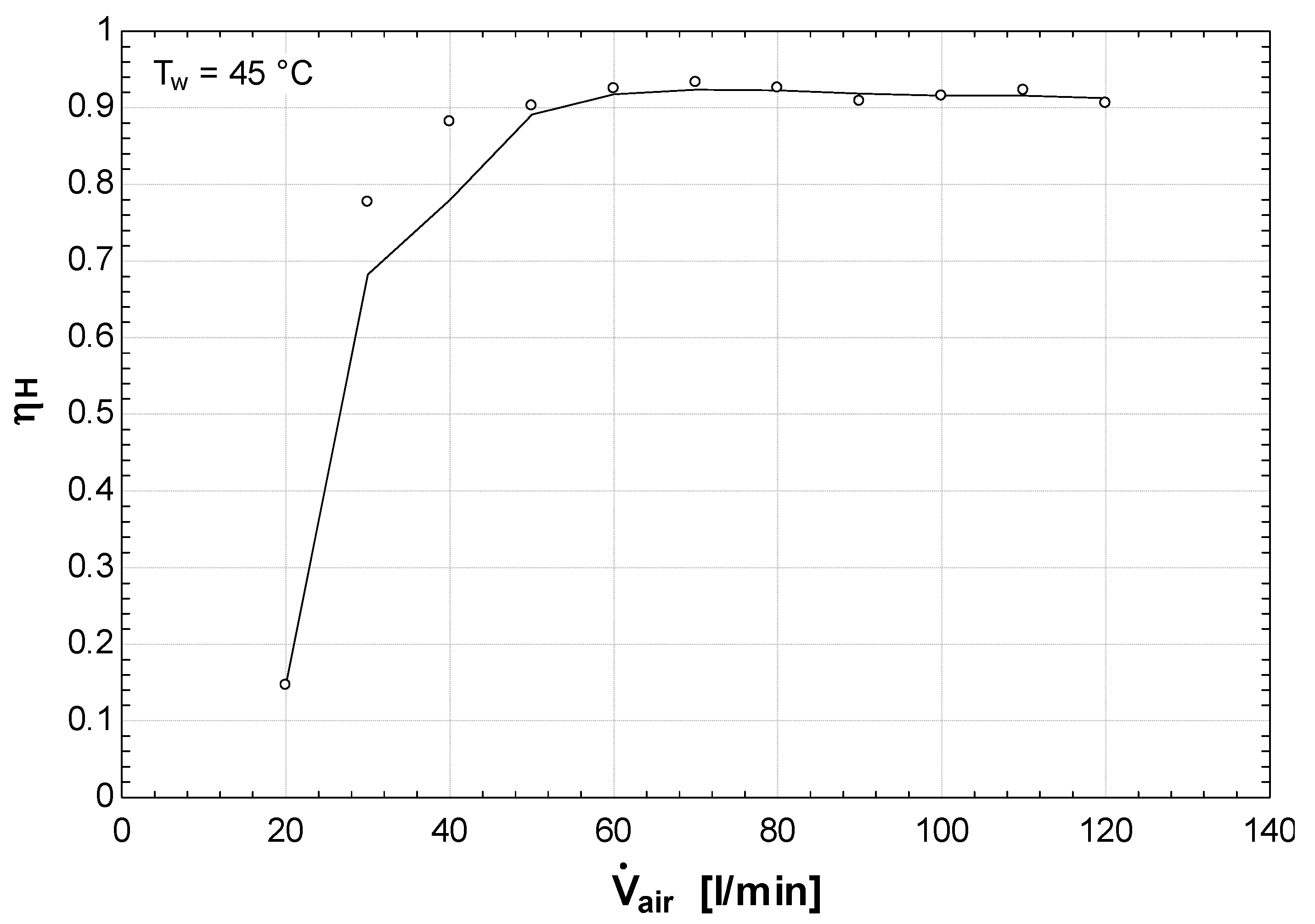
Figure 6 illustrates the humidification efficiency variation with airflow rate, at a water temperature of 45 °C. The efficiency shows a rapid increase at low flow rates, reaching above 90% once the flow exceeds approximately 50 L/min. This sharp improvement indicates an enhanced mass transfer as more dry air becomes available to absorb the atomized droplets. The stabilization of the efficiency above 90% across a wide flow range (50–110 L/min) suggests a well-balanced interaction between the ultrasonic transducer’s droplet generation rate and the air’s moisture absorption capacity. This equilibrium phenomenon aligns with findings by Shehata et al. [
16], who observed that ultrasonic foggers achieve their maximum performance when atomization rates match the air’s vapor-carrying capacity, enabling stable high-efficiency operation across varying airflow conditions.
Figure 7 demonstrates the system’s outstanding humidification performance, at 60 °C, with its efficiency exceeding 95% at approximately 60 L/min and maintaining this high level consistently up to 120 L/min. This behavior confirms that the greater thermal energy available at this elevated temperature significantly enhances vaporization and facilitates rapid air saturation. The sustained high efficiency across the entire flow range, without the decline at high flow rates observed at lower temperatures, indicates that the increased water temperature overcomes the limitation of the reduced residence time at high flow rates. The increase in water temperature reduces surface tension and enhances the droplet atomization and evaporation. This performance enhancement aligns with findings by El-Said and Abdelaziz [
14], who reported that ultrasonic atomizers operating above 50 °C maintain near-saturation conditions even at elevated airflow rates, due to improved evaporation kinetics and reduced water surface tension.
Figure 8,
Figure 9,
Figure 10 and
Figure 11 illustrate humidification water vapor production, analyzing the relationship between the water vapor production rate (
) and the airflow rate, at different water temperatures. The objective is to understand how the amount of vapor generated by the ultrasonic humidifier varies as thermal and flow conditions change.
Experimental evaluations were carried out at four water temperatures: 30 °C, 35 °C, 45 °C, and 60 °C. In each case, the airflow rate was gradually increased from 20 to 125 L/min, and the mass of vapor produced per hour was measured. These tests allow for the identification of the system’s dynamic behavior and its vapor-generation capacity under different levels of thermal energy input.
The resulting graphs show a growing trend in with increasing airflow rate, though the slope and saturation point vary depending on the water temperature. This analysis is key to determining the effective capacity of the system, as well as its energy adaptability under varying operational conditions.
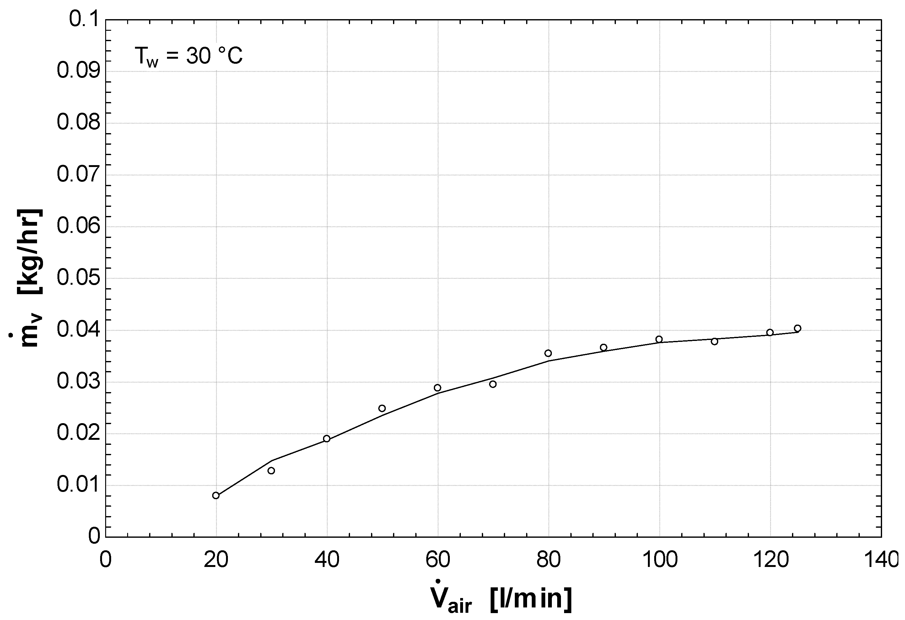
Figure 8 indicates a positive correlation between airflow and water vapor production at 30 °C. As airflow increases, a greater volume of dry air passes through the humidifier, increasing its capacity to transport vaporized water molecules. Consequently, the vapor production rate shows a progressive increase across the measured range. However, the curve reveals a decreasing rate of increase as the airflow exceeds 80 L/min, suggesting a trend toward saturation. This behavior can be attributed to the limited energy input at 30 °C, which restricts the rate of vapor generation despite the availability of additional airflow. This thermal limitation phenomenon aligns with findings by Abed et al. [
18], who observed that in ultrasonic humidification systems, vapor production becomes constrained by available thermal energy rather than airflow capacity when operating at lower temperatures. As a result, the system’s ability to further increase its vapor production is limited by thermal conditions rather than by flow dynamics, which is consistent with mass transfer principles in thermally limited evaporation processes.
Figure 9 shows the water vapor production rate at 35 °C, reaching a maximum value of approximately 0.05 kg/h. This represents a significant increase compared to the maximum of 0.04 kg/h observed at 30 °C (
Figure 8), demonstrating the positive effect of elevated temperature on vapor generation. The higher thermal energy, at 35 °C, provides more energy to overcome the water’s latent heat of vaporization, resulting in enhanced atomization efficiency. This temperature-driven performance gain corroborates studies by Shehata et al. [
16], where thermal augmentation in ultrasonic atomizers was linked to improved nebulization efficacy through decreased cohesive forces and accelerated droplet nucleation. The data confirm that a minimal temperature rise can significantly elevate vapor production in HDH applications.
Figure 10 exhibits a nearly linear relationship between water vapor production and airflow rate at 45 °C, indicating that the system maintains efficient humidification across the tested flow range. This linear trend suggests that the thermal energy at 45 °C provides a sufficient driving force for vaporization, without reaching saturation limits. The consistent slope demonstrates that vapor generation keeps pace with increasing air capacity to transport moisture. This behavior aligns with findings by El-Said et al. [
15], who observed linear vapor production trends in hybrid solar ultrasonic systems operating in the 40–50 °C range, attributing this to the optimal balance between thermal input and ultrasonic atomization efficiency. The results confirm that 45 °C represents an operational sweet spot, where thermal and flow parameters synergistically enhance performance.
Figure 11 demonstrates the optimal performance of the ultrasonic humidifier at 60 °C, showing a pronounced increase in water vapor production from 20 to 110 L/min. This robust upward trend reflects the enhanced evaporation kinetics, where elevated thermal energy reduces water surface tension and facilitates molecular bond dissociation, thereby increasing vaporization rates. The slight performance decline at 125 L/min suggests approaching the system’s maximum vapor transport capacity, where residence time limitations begin to affect saturation efficiency.
This performance characteristic corresponds with reports by Shehata et al. [
16] which indicate that ultrasonic HDH systems reach their maximum vapor output under combined high thermal energy (55–65 °C) and moderated airflow conditions, and establish an optimal regime for phase transition efficiency. The present results corroborate 60 °C as the most effective thermal level for maximizing vapor generation in ultrasonic humidification process.
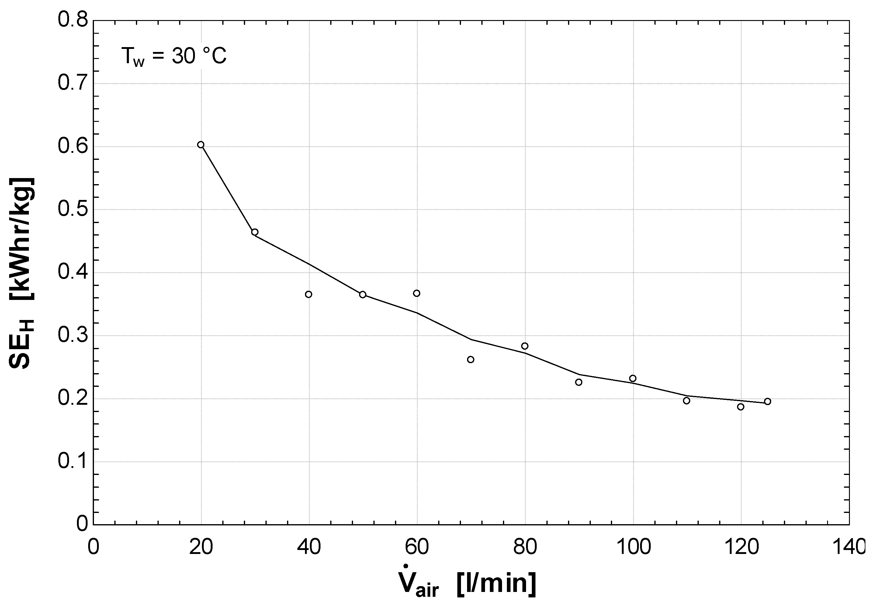
To comprehensively evaluate the energy performance of the ultrasonic humidifier, the specific energy consumption (SEh) was assessed. SEh is defined as the amount of thermal energy required to produce one kilogram of water vapor, and serves as a critical metric for determining the energy efficiency of the system under different operating conditions. By analyzing how SEh changes with different airflow rates at fixed water temperatures, valuable conclusions can be drawn about the device’s optimal operating range.
Figure 12,
Figure 13,
Figure 14 and
Figure 15 present the SE
h results for water temperatures of 30 °C, 35 °C, 45 °C, and 60 °C, highlighting the trade-offs between energy consumption and water vapor production. These findings are crucial for understanding the scalability and viability of ultrasonic humidification in HDH desalination systems, especially in resource-constrained environments where energy efficiency is paramount.
Figure 12 shows a decreasing trend in specific energy consumption (SE
h) with increasing airflow rate at 30 °C. The SE
h declines from approximately 0.60 kWh/kg at 20 L/min to 0.19 kWh/kg at 120 L/min, indicating a significant improvement in energy efficiency. This reduction occurs because the fixed thermal energy input is distributed across a greater mass of vapor produced as airflow increases. The stabilization of SE
h beyond 100 L/min suggests the system approaches its maximum vapor transport capacity under these thermal conditions. This behavior aligns with the thermodynamic principles governing energy efficiency in humidification processes, where increased mass flow rates enhance energy utilization by improving heat and mass transfer coefficients [
3]. Similar trends have been observed in packed-bed humidification systems, where higher airflow rates reduce specific energy consumption until system limits are reached [
13].
In
Figure 13, the specific energy consumption (SE
h) continues to exhibit a decreasing trend as the airflow rate increases. Initially, the SE
h value is relatively high, around 0.72 kWh/kg at 20 L/min, indicating inefficient operation due to limited vapor generation. However, a substantial drop occurs between 30 L/min and 40 L/min, reducing SE
h to approximately 0.30 kWh/kg. This sharp decline reflects a significant improvement in energy efficiency, likely due to the enhanced vaporization at moderate flow rates. Beyond 40 L/min, SE
h continues to decline gradually, reaching a stable value close to 0.22 kWh/kg from 110 L/min onwards. This trend reinforces the importance of selecting appropriate airflow rates to minimize energy consumption, especially in low-temperature humidification systems. This behavior is consistent with thermodynamic principles governing air–water contact systems, where moderate flow rates typically optimize the trade-off between the residence time and transfer coefficients [
3]. The observed efficiency transition around 30–40 L/min aligns with findings from packed-bed humidification studies [
13], which report similar critical flow thresholds for energy optimization. The results underscore that selecting airflow rates above this critical threshold is essential for the efficient operation of low-temperature ultrasonic humidification systems.
Figure 14 (SE
h) shows a similar pattern to that at lower temperatures, with a clear decrease as the airflow rate increases. Starting at a value of approximately 0.66 kWh/kg at 20 L/min, there is a marked reduction in SE
h, reaching around 0.38 kWh/kg at 40 L/min. This initial drop suggests a significant improvement in the energy efficiency of the ultrasonic humidifier, driven by the increased mass and heat transfer capacity. From that point on, the curve stabilizes with slight fluctuations, remaining in a range between 0.33 and 0.38 kWh/kg. This efficiency stabilization corresponds to previously reported optimal ultrasonic operations near 45 °C, where thermal and atomization rates achieve equilibrium [
14]. The invariant SE
h above 40 L/min confirms system reliability under variable flow conditions as an essential characteristic for renewable energy applications subject to airflow fluctuations.
Figure 15 reveals a distinct specific energy consumption (SE
h) profile at 60 °C, remaining nearly constant within 0.41–0.55 kWh/kg across the entire airflow range. This plateau indicates that the system has reached its fundamental efficiency limit, transitioning from thermally limited to transducer-limited operation. The behavior aligns with piezoelectric actuator studies [
19], where performance plateaus occur when mechanical output saturates, despite increased input, and it corresponds to HDH optimization principles [
3], where efficiency gains diminish beyond optimal temperature thresholds.
4. Conclusions
This study demonstrated that a single 1.7 MHz ultrasonic transducer with Venturi-shaped mixing achieves humidification efficiencies exceeding 95% across a broad airflow range (60–120 L/min), outperforming multi-transducer systems while maintaining a compact design. The optimal operational window was identified as 60 °C and 100–110 L/min, where vapor production reaches 0.08 kg/h—double the output at 30 °C. Key quantitative findings include the following: humidification efficiency peaks at 92–96% within 60–80 L/min airflow range, while specific energy consumption decreases from 0.72 kWh/kg at 20 L/min to 0.19–0.22 kWh/kg at high flows. At 60 °C, SEh stabilizes at 0.41–0.55 kWh/kg, indicating energy efficiency limits under maximum atomization conditions.
The system achieves 25–30% higher vapor production per degree Celsius temperature increase, with the most significant gain (40%) occurring between 45 °C and 60 °C. These performance metrics, coupled with its low thermal requirements (30–60 °C), position ultrasonic humidification as a viable solution for small-scale HDH desalination.
Overall, the findings demonstrate that ultrasonic humidification within HDH configurations offers a viable alternative for small-scale desalination processes, with the potential for optimization through appropriate operational adjustments. Further studies are recommended, including economic analysis, long-term performance evaluation, and system scalability to assess its applicability in real-world water supply scenarios. The scale-up of this system would likely involve the modular replication of transducer units rather than increasing transducer size, due to the physical limitations of piezoelectric materials. Additionally, maintaining humidification efficiency at larger scales would require careful management of the air–water distribution and pressure drop across the system. Future work should focus on modular design approaches to facilitate field deployment, enhance scalability, and simplify maintenance, while also considering economic analysis and fouling mitigation.

