Abstract
Fracture systems critically govern coal seam permeability, influencing hydrocarbon migration pathways and well placement strategies. We established a predictive framework for fracture characterization in thin-interbedded coal reservoirs by integrating seismic response analysis with multi-domain validation. Utilizing borehole log statistics and staggered-grid wave equation modeling, we first decode azimuthal amplitude anisotropy patterns in fractured coal seams under varying lithological contexts. Key findings reveal that (1) isotropic thick surrounding rocks yield distinct fracture symmetry axis alignment (ellipse long-axis orientation shifts with layer velocity), while (2) anisotropic thin-interbedded host strata amplify azimuthal anisotropy ratios at mid–far offsets but induce prediction ambiguity under comparable fracture intensities. By applying azimuthally partitioned OVT data with optimized mid–long offset stacking, our amplitude ellipse fitting method demonstrates unique fracture solutions validated against structural, logging, and production data. This workflow resolves the multi-solution challenges in thin-layered systems, enabling precise fracture parameter prediction to optimize coalbed methane development in geologically complex basins.
1. Introduction
The connectivity between coal seams and aquifers, as well as the development degree and orientation of fracture systems in surrounding rocks and coal, significantly impacts coalbed methane (CBM) development strategies, including well-type selection, horizontal well trajectory design, fracturing optimization, and reservoir management [1,2]. In coal-bearing formations, fracture networks are typically well-developed, with key parameters including spatial distribution, orientation, and density exerting critical controls on hydrocarbon migration pathways, accumulation patterns, and ultimately reservoir potential [1,2].
The development of fractures is particularly evident in Carboniferous rocks, which are exposed to equivalent stresses caused by water and high temperatures [3]. Vertically dominant fracture systems are commonly modeled as horizontally transversely isotropic media in coal-bearing strata. These fracture networks induce significant seismic anisotropy, manifesting as directionally dependent wave propagation characteristics. The diagnostic anisotropic signatures observable in seismic responses provide critical physical constraints for fracture characterization. Current methodologies for modeling this anisotropic behavior employ advanced numerical techniques: (1) T-matrix formulation for frequency-dependent stiffness tensor modeling, (2) high-order finite-difference schemes for viscoelastic anisotropic wavefield simulations, and (3) coupled T-matrix/staggered-grid finite-difference implementations to resolve 3D3C seismic responses in fractured media [4,5]. These computational approaches enable systematic investigation of fracture-induced seismic dispersion and attenuation patterns essential for quantitative fracture parameter inversion.
Chinese researchers have pioneered transformative methodologies in fractured media seismic analysis through dual advancements in anisotropic wavefield simulation and multi-physics AVO inversion. Their innovations encompass: (1) Development of hybrid computational frameworks combining finite-difference, reflectivity, and discontinuous Galerkin finite-element methods, enhanced by adaptive grid optimization and perfectly matched layer (PML) boundary conditions to achieve high-fidelity modeling of complex fracture networks; (2) Establishment of a fracture-sensitive AVO theory incorporating viscoelastic Biot-Gassmann models that quantify relationships between azimuthal reflection coefficients and fracture parameters (density, orientation, infill saturation). These breakthroughs enable decimeter-scale fracture characterization through machine learning-assisted inversion of frequency-dependent anisotropy signatures, fundamentally advancing coalbed methane reservoir assessment and production prediction capabilities.
Contemporary fracture characterization methodologies span geological analysis, geomechanical modeling, and seismic inversion techniques [6,7,8,9,10,11,12,13,14,15]. While conventional approaches predominantly rely on t anisotropic Zoeppritz formulations and their linearized approximations under single-interface assumptions to derive compliance tensors and crack weakness parameters through AVO/AVAZ inversion, these frameworks prove inadequate for thin-bedded reservoirs. Unlike single-interface reflections, thin interbedded reflections are actually composite wavefields superimposed by top and bottom reflections, interlayer multiples, and converted waves. Therefore, AVO/AVAZ inversion based on single-interface reflection prediction methods for coal seam fractures in thin interbeds is no longer applicable.
Fracture prediction methodologies encompass diverse approaches, including geological analysis, well logging, structural stress field numerical simulations, and seismic techniques [16,17]. Current methods predominantly rely on single-interface assumptions, employing anisotropic Zoeppritz equations and their approximations to compute AVO responses and invert fracture parameters such as compliance, weakness, and anisotropy coefficients. However, thin interbedded coal seams contrast sharply with single-interface reflection models. The seismic reflections observed in thin layers represent composite wavefields resulting from the superposition of multiple wave components: primary reflections from layer boundaries, interlayer multiples, and mode-converted waves. Consequently, conventional AVO/AVAZ inversion frameworks, designed under single-interface theoretical constraints, prove inadequate for characterizing fractures in thin interbedded coal seams [18,19].
Extensive analysis of field data reveals that coal seams exhibit pronounced seismic anisotropy, characterized by elliptical distributions in key seismic attributes. The application of Offset Vector Tile (OVT) technology to wide-azimuth seismic datasets effectively preserves azimuth-dependent offset information while capturing directional anisotropy patterns inherent to coal formations, thereby establishing a robust foundation for fracture characterization. Building upon this framework, this study develops a dual-methodology approach: (1) a wave-equation-based forward modeling system integrating well-log and acoustic array data to simulate anisotropic wave propagation in fractured coal seams, and (2) quantitative relationships between elliptical anisotropy signatures and fracture network parameters (density, orientation). Forward modeling demonstrates two critical insights: the major axis of anisotropy ellipses aligns with fracture symmetry directions, and anisotropic amplitude variations reach maximum sensitivity at mid–far offsets (20–45° incidence angles). To overcome the limitations of conventional AVAZ inversion constrained by single-interface assumptions, the proposed workflow employs azimuthally partitioned substacks of mid–far offset data optimized for noise suppression. Validation through structural interpretation, borehole fracture analysis, and production metrics confirms decimeter-scale accuracy in predicting fracture density and orientation [20,21,22].
2. Method and Principles
2.1. Seismic Forward Modeling of Fractures in Thin Interbeds
When the symmetry axis of fractures in the medium is horizontal, it is referred to as an HTI medium, used to approximate the transverse isotropy caused by vertically aligned fractures due to structural stress. The constitutive equation in HTI media is as follows:
Numerical simulation is performed using the first-order velocity–stress elastic wave equation. In a Cartesian coordinate system, the first-order velocity–stress elastic wave equation can be described as follows:
where represents stress variables, including normal and shear stresses, and represents the corresponding strain components. , , and are the particle velocity components. The matrix parameter is related to the elastic parameters of the medium, such as velocity and density, where , , , etc. To describe a fractured formation as an HTI anisotropic model, the anisotropy matrix needs to be calculated. For a model with a vertical symmetry axis and transverse isotropy, anisotropy coefficients ε ≤ 0.2, σ ≤ 0.2, and γ ≤ 0.2 indicate that coal is a weakly anisotropic medium [23]. Therefore, under the weak anisotropy assumption, Thomsen anisotropy parameters provide clearer meanings for describing HTI media. The relationship between the elastic parameters of an HTI medium and Thomsen parameters is as follows:
where is the density, is the P-wave velocity in the background medium, is the S-wave velocity in the background medium, and are dimensionless anisotropy parameters for the HTI medium. In a fracture medium model, the relationship between Thomsen parameters and fracture density is given as follows:
After establishing the wave equation for the HTI medium, the high-order staggered-grid finite difference method is used to solve the wave equation. The calculation equation for the 2N-order accuracy finite difference of the first-order spatial derivative in a staggered grid is as follows:
Using Equation (5), the recursion equation for wave Equation (2) is calculated as follows:
where is the time difference interval; the superscript denotes the moment of ; denotes ; denotes ; i, j, denotes the location of the spatial difference lattice point; denotes ; denotes ; and , , , are the difference operators. For the function , the forward difference and the backward difference operator along the x direction are as follows, respectively:
The values of the corresponding differential weighting coefficients for different spatial differential accuracies are as follows:
Based on the established wave equation and fracture parameter calculation equation, average data from multiple wells in the work area are used to calculate the P-wave and S-wave velocities and densities of the coal seam and its upper and lower layers. This establishes a seismic–geological model, conducting numerical simulation of the coal seam fracture seismic wavefield in a thin interbed background, providing theoretical support for predicting fracture characterization parameters.
2.2. Seismic Prediction of Fracture Characterization Parameters in Thin Interbeds
Under a strike-slip stress mechanism, nearly vertical shear fractures and tensile fractures are mainly formed [24]. Nearly vertical fractures in reservoirs can be approximated as HTI media, having two mutually perpendicular symmetry planes. The plane formed by the symmetry axis and the vertical line is called the symmetry axis plane, and the plane perpendicular to the symmetry axis is called isotropy. Figure 1 shows a schematic of azimuthal anisotropy in HTI media [25,26,27,28,29,30]. Due to the difference in the absorption degree of the fracture to the amplitude in different directions, the amplitude attenuation is the largest in the direction perpendicular to the fracture and the smallest in the direction parallel to the fracture, and the amplitude shows obvious azimuthal anisotropy and elliptical characteristics in plane space.
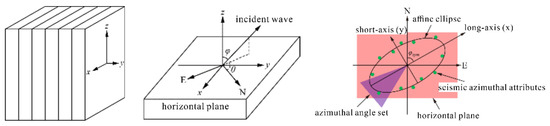
Figure 1.
Diagram of azimuthal anisotropy in HTI media.
Based on the Thomsen coefficients in HTI media and under the weak anisotropy assumption, Rüger derived the equation for the variation in the P-wave reflection coefficient with azimuth and incident angle:
where Rpp is the longitudinal wave reflection coefficient; α is the longitudinal wave velocity; β is the transverse wave velocity; Z is the wave impedance; ρ is the density; G = ρβ2 denotes the transverse tangential modulus; Δ denotes the parameter difference between the upper and lower interfaces; and the upper line denotes the mean value of the upper and lower interface parameters.
Under a fixed incident angle, the equation can be further simplified as follows:
In the equation, A, B, φsym are three fracture-related parameters, A can reflect the change in amplitude related to the gun checking distance, B reflects the change in amplitude with the orientation of the gun checking distance, φsym indicates the direction of the fracture, and B/A, i.e., the ratio of the long and short axes of the amplitude ellipse, can be used as a relative measure of the density of the fracture.
3. Simulation of Seismic Response of Fractured Coal Seams in Thin Interbeds
Based on the thin interbed characteristics of coal-bearing strata, we constructed three representative seismic geological models as shown in Figure 2: isotropic thick layers clamping HTI thin layers (Figure 2a), isotropic thin interlayers clamping HTI thin layers (Figure 2b), and HTI thin interlayers clamping HTI thin layers (Figure 2c). Each model has a horizontal size of 1000 m and a vertical size of 750 m.
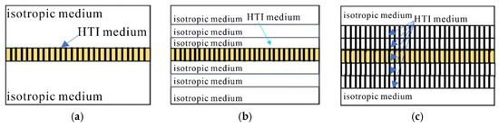
Figure 2.
Diagram of three types of forward modeling: (a) Isotropic thick layers clamping HTI thin layers; (b) isotropic thin interlayers clamping HTI thin layers; (c) HTI thin interlayers clamping HTI thin layers.
To clarify the indicative effect of the intermediate layer’s velocity on the fracture orientation, the intermediate layer was designed as either a low-velocity layer (e.g., coal seam) or a high-velocity layer (e.g., carbonate rock). The elastic parameters of the models are shown in Table 1, and all elastic parameters are from logging data. We used a second-order temporal and eighth-order spatial staggered grid finite difference forward simulation. The spatial grid size was set to 2 m, and the source wavelet was a Ricker wavelet with a dominant frequency of 35 Hz. The source was excited on the left side, and 501 geophones received the seismic signals. Forward simulations were conducted for different fracture densities, ranging from 0 (equivalent to isotropic) to 0.1, with intervals of 0.01. Simulations were performed for different azimuth angles (from 0° to 360°, with intervals of 5°) to study the seismic wavefield characteristics of HTI media under different observation systems. The azimuth angle perpendicular to the fracture strike was set to 0°.

Table 1.
Parameters of isotropic thick layer clamped HTI thin layer model.
The seismic forward modeling results for the HTI thin layer clamped by isotropic thick layers indicate that the greater the fracture density, the more significant the differences in seismic records at different azimuths (Figure 3). Figure 4 shows the pre-stack seismic gathers with a shot-receiver offset of 1000 m for different fracture densities (0, 0.02, 0.06, 0.10). The horizontal axis represents different azimuths, and the reflection P-wave appears at approximately 0.33 s in the 90° azimuth (isotropic plane). Figure 4a shows the data for a fracture density of 0 (isotropic medium), with no differences in reflection P-wave energy across different azimuths. From Figure 4b–d, as the fracture density increases from 0.02 to 0.10, significant differences in reflection P-wave energy appear at different azimuths. The higher the fracture density, the stronger the azimuthal anisotropy. The reflection wave energy is strongest at 0° and 180° azimuths (fracture symmetry axis direction) and weakest at 90° and 270° azimuths (fracture strike). Figure 5 shows the seismic gathers for a fracture density of 0.1 at offsets of 100 m, 400 m, 700 m, and 1000 m. The greater the offset, the stronger the azimuthal anisotropy. Combining the azimuthal gathers for different fracture densities and offsets, we observe that in the case of isotropic thick layers clamping low-velocity HTI thin layers, the amplitude azimuthal anisotropy is more pronounced, while the travel-time azimuthal anisotropy is weaker.
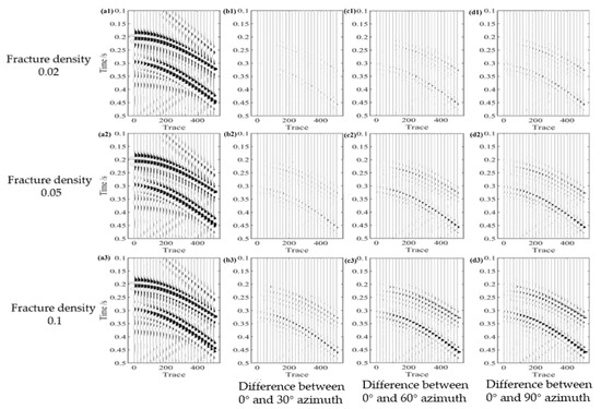
Figure 3.
Seismic shot records with different fracture densities and orientations: (a1–a3) are 0° shot gather records with fracture density of 0.02, 0.05 and 0.1 respectively, and (b1–b3,c1–c3,d1–d3) are the differences between 30° azimuth, 60° azimuth and 90° azimuth shot gather records with fracture density of 0.02, 0.05 and 0.1 respectively and 0° shot gather record.
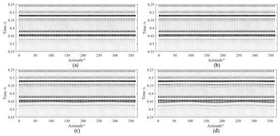
Figure 4.
Record of 1000 m offset gathers with different fracture densities: (a) fracture density of 0 (isotropic); (b) fracture density of 0.02; (c) fracture density of 0.06; (d) fracture density of 0.10.
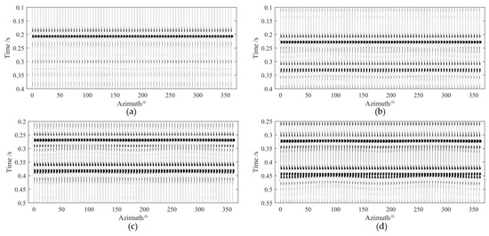
Figure 5.
Record of different offset gathers with a fracture density of 0.1: (a) 100 m offset; (b) 400 m offset; (c) 700 m offset; (d) 1000 m offset.
By extracting the amplitudes at the top surface of the intermediate layer at different azimuths and fitting them into ellipses, we found that regardless of whether the intermediate layer is high or low velocity, the greater the shot-receiver offset and fracture density, the stronger the azimuthal anisotropy of the reflected P-wave amplitude (Figure 6a). For low-velocity intermediate layers, the greater the fracture density and offset, the greater the ratio of the major to minor axis of the amplitude ellipse, with the reflection wave energy being strongest in the direction of the fracture symmetry axis (0°/180°) and weakest in the fracture strike direction (90°/270°). For high-velocity intermediate layers, the greater the fracture density and offset, the greater the ratio of the major to minor axis of the amplitude ellipse, but the major axis of the ellipse points in the direction of the fracture strike (Figure 6b).
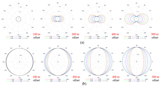
Figure 6.
Elliptical fitting of reflected P-wave amplitude for a single thin layer: (a) elliptical fitting of reflected P-wave amplitude for low-velocity intermediate layers; (b) elliptical fitting of reflected P-wave amplitude for high-velocity intermediate layers.
The elastic and physical parameters of Model 2 are shown in Table 2. The forward modeling parameters are consistent with those of Model 1, and all elastic parameters are from logging data. The fracture density of the low-velocity HTI layer in the sixth intermediate layer varies from 0 to 0.1, with intervals of 0.01. Forward simulations were performed at different azimuth angles (from 0° to 360°, with intervals of 5°). By extracting the amplitudes at the top surface of the intermediate layer at different azimuths and fitting them into ellipses, the forward results are shown in Figure 7. Compared to the results in Figure 6a, it can be observed that under the same conditions, the anisotropic characteristics are more pronounced when the HTI thin coal seam is clamped in isotropic thin interbeds, still showing the strongest reflection wave energy in the fracture symmetry axis direction and the weakest reflection wave energy in the fracture strike direction (90°/270°). Under the same fracture density and offset conditions, the azimuthal difference in amplitude is greater than that of a single HTI thin layer.
Table 2.
Parameters of HTI thin layer model clamped in thin interlayer isotropic media.
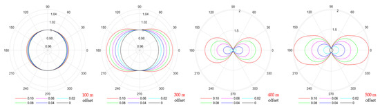
Figure 7.
Elliptical fitting of p-wave amplitude for HTI type thin layer reflection sandwiched by isotropic thin interlayers.
The parameters of Model 2 are shown in Table 3, and all elastic parameters are from logging data. This model consists of an 11-layer horizontal stratified structure, where the first and eleventh layers are isotropic homogeneous media, the seventh layer is a low-velocity layer containing vertical fractures, and the remaining layers are high-velocity layers containing vertical fractures. By extracting the amplitude at the top surface of the intermediate layer at different azimuths and performing elliptical fitting, we can compare the results of a single HTI thin layer clamped by isotropic thin interbeds (Figure 8). It can be observed that when a single HTI thin layer is clamped by anisotropic thin interbeds, the amplitude azimuthal anisotropy of the thin layer is not significant, with the ratio of the major to minor axes of the fitted ellipse being nearly 1. This also indicates that when the fracture development characteristics of the target layer and the surrounding rock are similar, it is difficult to predict the fractures in the target layer through the elliptical characteristics of amplitude or travel time.
Table 3.
Parameters of HTI thin layer model clamped in thin interlayer HTI anisotropic media.
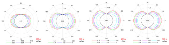
Figure 8.
Elliptical fitting of p-wave amplitude of HTI thin layer reflection sandwiched by the background of thin interlayer HTI anisotropic medium.
4. Prediction of Coal Seam Fracture System Based on Field Pre-Stack OVT Data
The elliptical fitting method is currently an effective approach for predicting fracture density and orientation using OVT data. This method is not constrained by the single-interface assumption related to fracture parameter inversion but instead utilizes the attribute information of different azimuths and offsets at each sampling point in the seismic data volume, which is more consistent with the characteristics of coal-bearing thin interbeds.
The elliptical fitting method requires pre-processed gather or stack data to be evenly divided by azimuth, and the attributes of data in each azimuth are then fitted. With sufficient fold coverage, the more azimuth divisions there are, the more finely the fracture orientation can be depicted. However, when the fold coverage is limited, too many azimuth divisions can compromise the signal-to-noise ratio of the data in each azimuth, thus affecting the prediction results. Based on the forward simulation and well-point elliptical fitting results from the previous section (Figure 9), we selected offsets ranging from 750–800 to 2800–2850 for elliptical fitting. To improve the stability of the calculation results, the azimuth angles were divided into 12 directions for stacking, and the stacked data volume was used for fracture parameter calculation.
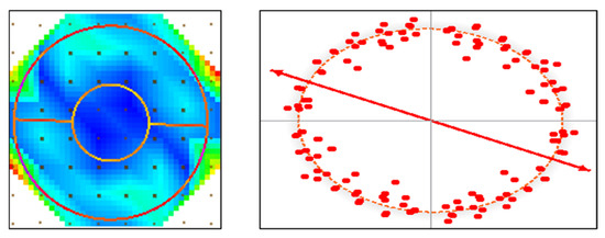
Figure 9.
Elliptical fitting results of OVT gather data for well FG-14.
Figure 10 shows the amplitude comparison results of stacked data volumes from different azimuths over the study area well. The ellipse position corresponds to the 8 + 9 coal seam. It can be observed that on azimuth-stacked data volumes centered at 0°, 45°, 90°, and 135°, there are certain amplitude differences, indicating significant azimuthal anisotropy (the red dashed circles). This suggests that predicting fracture development using the azimuthal anisotropy of seismic wave propagation is feasible.
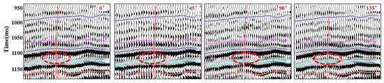
Figure 10.
Comparison of amplitude characteristics of stacked data volumes at different orientations through wells (from left to right: center orientations are 0°, 45°, 90°, and 135°, respectively).
Figure 11 presents the fracture development density profiles based on different data volumes over the well. It can be seen that the vertical fracture development characteristics predicted from OVT gathers and azimuth-stacked data are similar. However, the fracture development details predicted from OVT gathers are richer. In areas without significant structural changes, the anisotropy strength attributes predicted from partial offset stacking of OVT gathers can detect more microfaults and fractures compared to azimuth-stacked predictions.
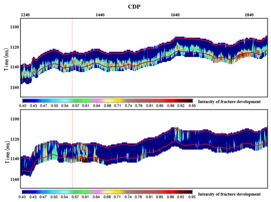
Figure 11.
Comparison of prediction of wellbore fractures using different trace sets (top: OVT trace sets stacked in azimuth for medium and long-distance migration; bottom: stacked in azimuth).
Figure 12 shows the plane distribution of fracture development degree and orientation in the main coal seam 8 + 9 in the SF block on the eastern edge of Ordos, predicted using the method proposed in this paper. The colors represent the degree of fracture development, and the white short lines indicate the fracture orientation. It can be seen that fractures are generally more developed in the central and southern parts, with the main body in the central part showing near north–south and northeast trends, while north–south trending strip-shaped fracture zones are also developed in the eastern part.
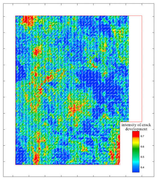
Figure 12.
Prediction of fractures in coal seam 8 + 9 based on OVT gathers.
5. Discussion and Conclusions
Currently, there are many methods for fracture prediction, mainly using different types of prestack data (azimuth stack data, prestack OVT gather data). The main difference is whether the offset information is fully utilized. Figure 13 shows the plane distribution of fractures calculated based on different data volumes. It can be seen from the figure that the fractures predicted based on the azimuth stack gather have obvious splicing footprints, but the plane distribution of fracture development calculated based on the OVT gather data has no obvious acquisition footprint characteristics. More microfaults and fractures can be predicted based on the anisotropic strength attributes of OVT gathers than the azimuthal stack attributes. Therefore, the prestack attribute prediction method based on OVT gather is selected for fracture prediction.
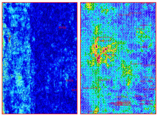
Figure 13.
Comparison of fracture prediction results of coal seams 8 + 9 based on azimuth stacking data (left) and OVT gather (right).
The left part of Figure 14 shows the horizontal stress difference results of the 8 + 9 coal seam, where compressive–torsional strike-slip faults are marked in red, extensional-torsional strike-slip faults in blue, normal faults in magenta, and reverse faults in green. The right part of Figure 14 shows the superposition of the strength of fracture development and the horizontal stress difference of the 8 + 9 coal seam. Analysis reveals a good correlation between fracture development and the distribution of horizontal stress difference, with fractures mainly developing between two sets of compressive–torsional strike-slip zones. The seismic fracture prediction results are consistent with regional geological understanding.
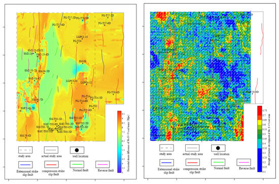
Figure 14.
Comparison between the predicted results of coal fractures and the structural interpretation results of coal seams 8 + 9.
The reliability of the fracture prediction results was verified by analyzing the intersection of gas production results and fractures. The seismic predicted fracture strength at well points in the 8 + 9 coal seam was extracted, and an intersection analysis was performed with peak gas production and average gas production results of the 8 + 9 coal seam. The intersection results, shown in Figure 15, indicate a good correlation between the strength of fracture development and both average and peak gas production, with a correlation coefficient of approximately 0.7. This demonstrates that the pre-stack seismic fracture prediction results based on OVT gathers are reliable.

Figure 15.
Intersection diagram between the development strength of fractures in coal seams 8 + 9 and the production capacity of coalbed methane.
Generally, anisotropy analysis results at well points can accurately represent the fracture development direction. Therefore, the anisotropy analysis results at well points were compared with the seismic predicted fracture development directions at the same well points to verify the reliability of the prediction results. Figure 16 shows the comparison between the seismic predicted fracture orientations and the measured orientations at well points for the 8 + 9 coal seam. The main characteristics of both are consistent, predominantly showing northeast and north–south orientations. Fractures are more developed near fault zones, and the fracture orientations are consistent with the measured well point orientations, showing good correlation with gas production data. This indicates that the fracture prediction results obtained using the method proposed in this paper are consistent with regional geology, well logging predictions, and gas production performance, demonstrating that the pre-stack seismic fracture prediction results based on OVT gathers are reliable and have certain guiding significance for coalbed methane development.
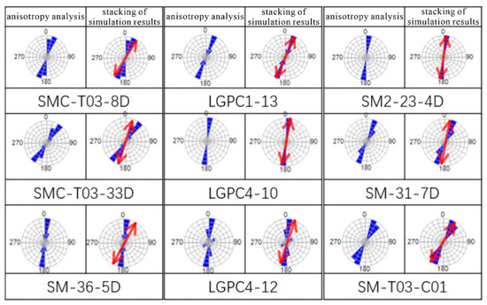
Figure 16.
Comparison of predicted fracture development direction and well point anisotropy analysis results for coal seam 8 + 9.
For the first time, we have elucidated the seismic response characteristics of HTI (horizontally transversely isotropic) fracture systems in coal seams under coal-bearing formation conditions. The forward simulation results of fracture wave equations under the background of thin interbeds show that when the thin layer is low-velocity, the major axis of the fitted ellipse points in the direction of the fracture symmetry axis; when the thin layer is high-velocity, the major axis points in the direction of the fracture strike. This is also the main difference between coal seams and conventional high-velocity reservoirs.
When the top and bottom plates of a single-fracture-type coal seam are anisotropic thin interbeds, the amplitude azimuthal anisotropy of the coal seam is stronger, and the ratio of the major to minor axes of the fitted ellipse is greater compared to when the top and bottom plates are thick layers. As the offset increases, the elliptical characteristics become more evident. When the top and bottom plates of thin coal seams are anisotropic thin interbeds, the amplitude azimuthal anisotropy of the coal seam is not strong. When the fracture density of the coal seam is similar to that of the surrounding rock, the ratio of the major to minor axes of the fitted ellipse approaches, making it difficult to predict fracture development characteristics.
Based on the forward simulation results, the elliptical fitting of amplitude was performed using the azimuthal mid-to-far offset stacked data volumes of the OVT data body to predict the fracture development characteristics in the actual work area. The reliability of the proposed method was verified through multidimensional comparison with geological, well logging, and production data. However, because seismic data stacking is not carried out to suppress noise, fracture prediction based on OVT gathers requires a high signal-to-noise ratio of OVT gathers; otherwise, a large number of false anomalies will be produced [31,32].
The ellipse fitting result based on forward modeling optimization of azimuth-medium and long offset gather data is more consistent with the actual fracture development in the work area. Seismic data in the OVT domain retain the azimuth information better. Compared with the sub-azimuth stack data, the anisotropic characteristics of far offset are more obvious, which is conducive to the study of reservoir anisotropy and fracture prediction. The velocity of seismic data in the OVT domain shows the anisotropic characteristics related to fractures, which can be effectively used to predict the fracture system. The fracture density predicted by prestack seismic data can delineate the fracture development area, and the fracture direction can guide the drilling direction of the horizontal well.
Author Contributions
Conceptualization, K.W. and Y.Q.; methodology, S.Z. and F.H.; software, S.Z.; validation, S.C., T.Z., F.G. and Y.Y.; investigation, Y.Y.; resources, K.W.; writing—original draft preparation, S.Z.; writing—review and editing, K.W.; visualization, S.Z.; supervision, S.Z.; project administration, K.W.; funding acquisition, K.W. and S.Z. All authors have read and agreed to the published version of the manuscript.
Funding
This research was funded by the National Key R&D Program of China, grant number 2024YFC2909400, Topic 1 of China National Offshore Oil Corporation’s “14th Five Year Plan” Major Science and Technology Project, grant number KJGG2022-1001, the National Natural Science Foundation of China, grant number 42102212, and Fundamental Research Program of Shanxi Province, grant number 202303021211058.
Data Availability Statement
The original contributions presented in this study are included in the article. Further inquiries can be directed to the corresponding author.
Conflicts of Interest
Authors Kui Wu, Yu Qi, Feng He and Silu Chen were employed by the CNOOC Research Institute Ltd. The remaining authors declare that the research was conducted in the absence of any commercial or financial relationships that could be construed as a potential conflict of interest.
References
- Yang, C.; Zhang, H.; Wang, Y. Simulation analysis of fluid seismic detectability in coal seams. Chin. J. Geophys. 2018, 61, 1605–1614. [Google Scholar]
- Zheng, S.; Yao, Y.; Elsworth, D.; Liu, D.; Cai, Y. Dynamic fluid interactions during CO2-enhanced coalbed methane and CO2 sequestration in coal seams. Part 1: CO2–CH4 interactions. Energy Fuels 2020, 34, 8274–8282. [Google Scholar] [CrossRef]
- Skrzypkowski, K.; Zagórski, K.; Zagórska, A. Determination of the Extent of the Rock Destruction Zones around a Gasification Channel on the Basis of Strength Tests of Sandstone and Claystone Samples Heated at High Temperatures up to 1200 °C and Exposed to Water. Energies 2021, 14, 6464. [Google Scholar] [CrossRef]
- Johansen, T.A.; Jakobsen, M.; Agersborg, R.; Ruud, B.O. The PP and PS response of a fractured reservoir. In Proceedings of the SEG International Exposition and Annual Meeting, Denver, CO, USA, 10–15 October 2004; p. SEG-2004-0199. [Google Scholar]
- Hu, Y.; McMechan, G. Sensitivity of three-component 3D finite-difference elastic seismic modeling to inclusion parameters in HTI and TTI media with high inclusion density. Geophysics 2010, 75, T49–T61. [Google Scholar] [CrossRef]
- Bloch, W.; John, T.; Kummerow, J.; Salazar, P.; Krüger, O.S.; Shapiro, S.A. Watching dehydration: Seismic indication for transient fluid pathways in the oceanic mantle of the subducting Nazca slab. Geochem. Geophys. Geosystems 2018, 19, 3189–3207. [Google Scholar] [CrossRef]
- Cui, X.; Lines, L.; Krebes, E.S.; Peng, S. Seismic Forward Modeling of Fractures and Fractured Medium Inversion; Springer: Berlin/Heidelberg, Germany, 2018. [Google Scholar]
- Du, Q.; Dong, Y.; Yang, H.; Wang, Y. Shear Wave Velocity Estimation in HTI Media. In Theoretical and Computational Acoustics 2001; World Scientific: Singapore, 2002; pp. 397–408. [Google Scholar]
- Guochen, W.; Haixu, Q. Rotated staggering grid forward modeling in fractured medium. Acta Seismol. Sin. 2014, 36, 1075–1088. [Google Scholar]
- Li, Q.; LI, Y.; LI, Q. Seismic response of anisotropic coal beds with vertical cracks. Chin. J. Geophys. 2019, 62, 306–315. [Google Scholar]
- Liao, J.; Zhang, Q.; Zhou, L. A research on forward modeling method of viscoelastic Chapman-Kelvin model based on partially saturated rock. Chin. J. Geophys. 2024, 67, 347–369. [Google Scholar]
- Liu, C.; Liu, Y.; Feng, X.; Lu, Y. Constructing the convex quadratic function for the evaluation of crack density of HTI media using P-and converted waves. J. Geophys. Eng. 2012, 9, 729–736. [Google Scholar] [CrossRef]
- Liu, Y.; Zhu, Z.; Pan, R.; Gao, B.; Jin, J. Analysis of AVAZ seismic forward modeling of fracture-cavity reservoirs of the dengying formation, Central Sichuan Basin. Energies 2022, 15, 5022. [Google Scholar] [CrossRef]
- Mäkinen, A.M.; Deuss, A. Normal mode splitting due to inner core attenuation anisotropy. Geophys. J. Int. 2013, 195, 1786–1795. [Google Scholar] [CrossRef]
- Sengupta, M.; Bachrach, R.; Prioul, R. Forward modeling the wide-azimuth seismic response of fractured reservoirs. In SEG Technical Program Expanded Abstracts 2009; Society of Exploration Geophysicists: Houston, TX, USA, 2009; pp. 2080–2084. [Google Scholar]
- Aghli, G.; Moussavi-Harami, R.; Tokhmechi, B. Integration of sonic and resistivity conventional logs for identification of fracture parameters in the carbonate reservoirs (A case study, Carbonate Asmari Formation, Zagros Basin, SW Iran). J. Pet. Sci. Eng. 2020, 186, 106728. [Google Scholar] [CrossRef]
- Maity, D.; Aminzadeh, F. Novel fracture zone identifier attribute using geophysical and well log data for unconventional reservoirs. Interpretation 2015, 3, T155–T167. [Google Scholar] [CrossRef]
- Shi, Y.; Yu, B.; Zhou, H.; Cao, Y.; Wang, W.; Wang, N. FMG_INV, a fast multi-Gaussian inversion method integrating well-log and seismic data. IEEE Trans. Geosci. Remote Sens. 2024, 62, 4503112. [Google Scholar] [CrossRef]
- Yu, B.; Shi, Y.; Zhou, H.; Cao, Y.; Wang, N.; Ji, X. Fast Bayesian linearized inversion with an efficient dimension reduction strategy. IEEE Trans. Geosci. Remote Sens. 2024, 62, 4502910. [Google Scholar] [CrossRef]
- Ding, P.; Wang, D.; Li, X.-Y. An experimental study on scale-dependent velocity and anisotropy in fractured media based on artificial rocks with controlled fracture geometries. Rock Mech. Rock Eng. 2020, 53, 3149–3159. [Google Scholar] [CrossRef]
- Li, S.; Wen, X.; Pu, Y.; Miao, Z.; Yuan, M. Fracture prediction based on attenuative anisotropy theory and its application to a shale gas reservoir. J. Geophys. Eng. 2023, 20, 196–210. [Google Scholar] [CrossRef]
- Shifan, Z.; Maoshan, C.; Lei, L.; Chunfeng, T.; Zhonghong, W.; Xiaohui, Z. Offset vector tile domain wide-azimuth prestack seismic interpretation methods and applications. Interpretation 2018, 6, T337–T347. [Google Scholar] [CrossRef]
- Dong, S.H.; Tao, W.P. Test on elastic anisotropic coefficients of gas coal. Chin. J. Geophys. 2008, 51, 671–677. [Google Scholar] [CrossRef]
- Cui, F.; Jia, C.; Lai, X.; Yang, Y.; Dong, S. Study on the law of fracture evolution under repeated mining of close-distance coal seams. Energies 2020, 13, 6064. [Google Scholar] [CrossRef]
- Feng, Y.; Zong, Z.; Zhang, G.; Lang, K.; Chen, F. PP-wave reflection coefficient equation for HTI media incorporating squirt flow effect and frequency-dependent azimuthal AVO inversion for anisotropic fluid indicator. IEEE Trans. Geosci. Remote Sens. 2024, 62, 5906212. [Google Scholar] [CrossRef]
- Jin, S.; Stovas, A. Comparisons of moveout approximations and inversions for P-and S-waves in acoustic transversely isotropic media with a vertical symmetry axis. J. Appl. Geophys. 2019, 161, 216–227. [Google Scholar] [CrossRef]
- Liu, X.; Huang, H.; Wang, Y.; Zhang, S. P-wave azimuthal anisotropy analysis and fracture prediction application. In Proceedings of the SEG International Exposition and Annual Meeting, New Orleans, LA, USA, 18–23 October 2015; p. SEG-2015-5844728. [Google Scholar]
- Rüger, A. P-wave reflection coefficients for transversely isotropic models with vertical and horizontal axis of symmetry. Geophysics 1997, 62, 713–722. [Google Scholar] [CrossRef]
- Zhang, S.; Huang, H.; Dong, Y.; Yang, X.; Wang, C.; Luo, Y. Direct estimation of the fluid properties and brittleness via elastic impedance inversion for predicting sweet spots and the fracturing area in the unconventional reservoir. J. Nat. Gas Sci. Eng. 2017, 45, 415–427. [Google Scholar] [CrossRef]
- Talib, M.; Durrani, M.; Subhani, G.; Rahman, S. Faults/fractures characterization to improve well planning and reduce drilling risks–A case study from a tight carbonate reservoir in Pakistan. J. Seism. Explor. 2023, 32, 21–38. [Google Scholar]
- Li, Z.; Wang, G.; Zhu, C.; Chen, S. Enhancing seismic resolution based on U-Net deep learning network. J. Seism. Explor. 2023, 32, 315–336. [Google Scholar]
- Qiao, Z.; Chuai, X.; Xu, Z.; Guo, N.; Zhu, W.; Zhang, J.; Chen, W.; Xia, R. Seismic data enhancement based on Bayesian convolutional neural network. J. Seism. Explor. 2023, 32, 407–425. [Google Scholar]


Disclaimer/Publisher’s Note: The statements, opinions and data contained in all publications are solely those of the individual author(s) and contributor(s) and not of MDPI and/or the editor(s). MDPI and/or the editor(s) disclaim responsibility for any injury to people or property resulting from any ideas, methods, instructions or products referred to in the content. |
© 2025 by the authors. Licensee MDPI, Basel, Switzerland. This article is an open access article distributed under the terms and conditions of the Creative Commons Attribution (CC BY) license (https://creativecommons.org/licenses/by/4.0/).