Article

Innovative Surrogate Combustion Model for Efficient Design of Small-Scale Waste Mono-Incineration Systems

by
Anton Žnidarčič
1,
Tomaž Katrašnik
1,* and
Tine Seljak
2
1
Laboratory for Internal Combustion Engines and Electromobility, Faculty of Mechanical Engineering, University of Ljubljana, Aškerčeva 6, SI-1000 Ljubljana, Slovenia
2
Laboratory for Heat and Power, Faculty of Mechanical Engineering, University of Ljubljana, Aškerčeva 6, SI-1000 Ljubljana, Slovenia
*
Author to whom correspondence should be addressed.
Processes 2025, 13(10), 3170; https://doi.org/10.3390/pr13103170
Submission received: 12 August 2025 / Revised: 30 September 2025 / Accepted: 2 October 2025 / Published: 6 October 2025

Abstract

Small-scale thermal treatment systems can provide environmentally improved sewage sludge treatment due to processing sludge locally, which lowers transport costs and emissions. However, the combined effect of confined volume and complex sludge properties makes achieving strict regulations on flue gas emissions and end-ash composition challenging. System development thus requires the use of advanced, 3D CFD simulation supported studies. An important step forward regarding these is the application of combustion models which introduce tailored surrogate fuels and apply detailed chemical kinetics to achieve a high-fidelity combustion description in confined volumes. In relation to this, the paper presents an innovative computationally efficient sewage sludge surrogate-based combustion model capable of defining surrogates, tailored to sewage sludge, and capable of providing detailed insight into reaction zone evolution in small-scale sludge incineration systems. The validity of the proposed model and surrogates is confirmed via simulated temperatures differing from measurements in the small-scale system for less than 30 K. The validated model of a small-scale system is used in the parametric analysis of variable air–fuel ratios, higher fuel moisture presence, varying bed temperature, and varying thermal power to enable unprecedentedly accurate and efficient definition of design features of small-scale systems and to provide key guidelines for operation optimization.

1. Introduction

The increase in sewage sludge (SS) quantities across the EU over the last few decades [1] has necessitated increased treatment capacities. This corresponds with the introduction of circular economy solutions, which was backed by the first circular economy action plan in the European Union [2] and further stressed as one of the main development directions in the Green Deal [3]. Both documents emphasize the need to recover valuable materials and energy from non-recyclable and non-reusable waste, such as SS. Therefore, many novel methods have been proposed for SS treatment, such as anaerobic digestion (AD) with an electrochemical anaerobic membrane bioreactor [4] or hydrothermal carbonization (HTC) [5]. While a very recent review in [6] thoroughly lists these methods, it also stresses the technology maturity barriers which prevent their wide application. Consequently, the existing thermal treatment methods continue to present a highly interesting option to achieve higher energy and material recovery levels. This is especially important as the SS is recognized as a renewable fuel [7], while wastewater treatment plants exhibit high energy use [6]. Simultaneously, thermal treatment enables the removal of harmful SS substances, such as viruses, bacteria, heavy metals, and microplastics [8].
Thermal treatment of SS is, in the majority, performed by co-incineration in large-scale systems [9]. This is not a suitable circular economy solution as it dilutes and contaminates end-ash, which aggravates downstream valuable material recovery. Especially of phosphorus, of which the sludge is an important potential source [10]. Furthermore, co-incineration does not address the emerging requirements to introduce low transport, storage, and preparation costs of sludge alongside the need for ultra-low emissions. To overcome this challenge, particularly in areas with moderate-to-small sludge quantities, the introduction of small-scale, mono-incineration systems offers itself as one of the possible sustainable solutions. Such systems also lead to lower transport costs and emissions by enabling decentralized treatment of locally produced sludge. If adequately designed, they enable achieving optimized process conditions to support the production of end-ash with a suitable composition and structure for further material recovery.
Designing such advanced small-scale systems is, however, highly challenging. The reasons lie in their spatial constraints and the sludge properties, characterized by low calorific value due to high ash and moisture content. Following the discussion in [11], small-scale systems feature strong coupling between combustion and flow phenomena on all scales and are thus characterized by a much stronger interaction between the fuel bed and the freeboard. Thus, they are also highly sensitive to variations in thermodynamic parameters and sludge properties. Combined, this means that meeting the stringent flue gas emissions limits is highly challenging [6]. It is therefore not surprising that, currently, there exist only a few small-scale systems for SS mono-incineration, although the existing predictions point to the need for decentralized SS treatment [12], in which small-scale systems will play a crucial role. A brief description of the existing small-scale systems is provided in Table 1. Their common feature is dual-chamber construction. While sludge thermal decomposition takes place in the fuel-rich conditions of the primary chamber, the second chamber imposes complete combustion of the emitted volatiles. The reasons for this are the listed small-scale system properties and the strict flue gas emission limits that must be adhered to [5]. Consequently, a different design approach must be applied, where considerable frontloading in the form of detailed sludge combustion modeling is the key to adequate small-scale system design and combustion process control.
The use of detailed 3D CFD simulations can provide unprecedented insight into flow and combustion phenomena in spatially constrained volumes. However, as discussed in [11], the widely available reactive flow models for incineration systems do not readily provide a sufficient level of detail for an accurate description of complex fuel combustion in small-scale systems. This deficiency mainly arises from the fact that most published models of waste material combustion consider large-scale systems. The focus in these is given to the freeboard, which is at a relatively large distance from the fuel bed and features a highly turbulent, well-mixed flow field. Two simplifications arise from this, which limit the transfer of these models to small-scale systems.
The first is that the applied combustion models by default apply syngas species to describe the emitted volatiles, although heavier hydrocarbon species are also detected in waste [16] and sludge volatiles [17]. This approach is used, for instance, in describing refuse-derived fuel combustion in large-scale waste-to-energy systems [18] and in municipal solid waste (MSW) combustion simulations in [19,20]. Syngas species describe the emitted volatiles also in cases of pulverized fuel introduction, discussed in [21]. The second simplification is that the models, following the simplified volatile description, use simplified one- or two-step chemical kinetics. Examples where one-step reactions are used are co-incineration simulations of MSW and SS in [9], wood or MSW incineration simulations on a stationary bed in [22], and optimization of an MSW incineration system in [23]. Two-step reaction kinetics are applied in a waste wood combustion description in [24], in the consequent combustion optimization study in [25], and in pulverized fuel combustion simulations in [26].
The noted two simplifications can lead to poor prediction capabilities in the case of small-scale systems, as heat release rates, combustion evolution, as well as associated temperature and concentration fields are not fully taken into account. Recently, important steps forward were made with the models that more thoroughly describe SS decomposition and combustion. In [27], a solid particle surrogate model is presented for SS, where a highly transferable chemical kinetics mechanism for the thermal decomposition description of solid SS is proposed. The model can provide a valid description of emitted volatiles. This is, however, currently too complex for practical inclusion in freeboard combustion simulations due to the number and variation in involved species during decomposition, leading to the need for extensive chemical kinetic mechanisms. A way to partially overcome this limitation is presented in [28], where a Steady Diffusion Flamelet model is applied to model the combustion of volatiles, emitted from pulverized SS after injection into a flash pyrolysis reactor. The volatiles are, therefore, described with a single surrogate. Consequently, the model enables a detailed and computationally efficient combustion description, albeit focused on quick sludge decomposition conditions. It was recently extended with the capability to simulate the slag flow in the furnace [29] and to account for the addition of other waste to the sludge [30].
The listed limitations of the recent developments and the necessary steps to enhance their capabilities can be addressed by applying the approach, capable of high-fidelity combustion modeling of variable sludge thermal decomposition products in confined volumes. An example of such an approach is presented with the surrogate-based combustion model in [11]. The model relies on the use of available SS thermal decomposition data from the literature, which is combined with the data from a purposely built experimental sludge combustion observation unit with low thermal power (below 5 kW) and laminar flow conditions. The abilities to obtain surrogates that meet observed combustion in the experimental unit and predict their combustion in detail using detailed chemical kinetic mechanisms are further upgraded with the ability to define reduced reaction mechanisms [31], which is key to the model’s computational efficiency.
Despite its advances, the model from [11] cannot be directly applied in small-scale system simulations. The main reason lies in the differences between the fuel bed of the experimental unit, applied in [11], and those of small-scale systems, such as those listed in Table 1. While the latter features fuel-rich conditions, the experimental unit imposes fuel-lean conditions in its bed. This crucially affects the composition of the surrogates through combustion that takes place in the fuel bed, making the model in [11] strongly linked to fuel lean conditions in the fuel bed. Additionally, small-scale systems feature turbulent flow conditions in the freeboard, leading to enhanced mixing and the impact of turbulence–kinetic interactions that are not present in the experimental unit. Combined, the differences between small-scale system and experimental unit conditions affect the predictive capabilities, gained with the model in [11] and its surrogates, effectively prohibiting the model from being directly applied in designing the small-scale SS incineration systems and their operating conditions.
To overcome the noted limitations of the published models, as well as those of the model in [11], and to develop a model suitable for computationally efficient high-fidelity prediction of SS combustion in small-scale systems, the manuscript presents the following:
(a) Innovative extension of the surrogate-based combustion model with definition of the surrogates that account for the fuel-rich conditions in the fuel bed of small-scale systems and, therefore, adequately describe combustion in their freeboard.
(b) Validation of the novel model and surrogates through experimental data, obtained from a specifically constructed small-scale system.
(c) Application of the validated model and surrogates in a parametric analysis that determines system operation control strategies in different operating conditions.
The presented contributions of the manuscript that lead to the final, novel sewage sludge surrogate-based combustion model for small-scale incineration systems rely on extensive research work, graphically indicated in Figure 1.
As pointed out in Figure 1, the devised innovative sewage sludge surrogate-based combustion model defines, for the first time, the surrogates that fit fuel-rich conditions in the fuel beds of small-scale systems through specific tailoring of the surrogates that accurately capture combustion evolution in the low thermal power experimental unit with laminar flow conditions. The ability to define tailored surrogates is key for the model to achieve high-fidelity modeling of flow and combustion field coupling in small-scale sludge incineration systems. The validation of the innovatively tailored surrogates and of the advanced model is performed by a comparison of numerically and experimentally obtained temperatures at two different positions in the freeboard of a specifically devised small-scale system. A close match of the temperatures confirms that the model accurately predicts combustion evolution in the spatially confined freeboard of the small-scale system. Furthermore, the application of the tailored surrogates with reduced reaction mechanism allows for an in-depth analysis of reaction zone evolution, extending from the temperature field to the concentration fields of various species. The validated model is then also used in the parametric analysis that further depicts its ability to provide an accurate and efficient definition of small-scale system design features as well as key guidelines for its operation optimization. The parametric analysis comprises variable mass flow ratios of the primary to secondary air, increased moisture presence in SS, variable bed temperature, and thermal power effects. Due to the listed advanced features, the model presents a 3D CFD-supported design tool for performing unprecedentedly accurate, yet computationally feasible, sludge combustion simulations in small-scale systems.
This paper initially introduces general sludge composition and thermal decomposition characteristics, which provide a foundation for presenting the innovative surrogate-based combustion model. Then, the description of the small-scale system, used for model validation, is given and followed by the description of the numerical setup applied in 3D CFD simulations. Section 3 first focuses on numerical and experimental confirmation of suitable small-scale system performance. Then, combustion simulations with the innovative model and tailored surrogates are discussed together with their validation. The successful validation is finally followed by the parametric analysis, which provides system operation control strategy guidelines.

2. Materials and Methods

Multiple steps that address all relevant scales and phenomena affecting sludge combustion need to be combined to arrive at the innovative surrogate-based combustion model and validate it as suitable for detailed sewage sludge combustion simulations in small-scale systems. These steps are described in the following subsections.

2.1. Description of Sewage Sludge Composition and Thermal Decomposition Properties

Sewage sludge is a highly complex fuel as its composition varies with origin and processing characteristics. Defining its properties requires time-consuming and costly measurements, which need to be carried out each time the sludge, subjected to thermal treatment, changes. To provide a strong and valid basis for the system and surrogate model development in a time- and cost-efficient manner, the work in [11] proposes characterization of the sludge through combining the data from the available literature and from the dedicated low thermal power (<5 kW) experimental unit for sludge combustion experiments. The experimental unit features laminar flow conditions that emphasize the chemical kinetic impacts on the combustion of sludge decomposition products. The system is further presented in the following section. Data from the literature provides a fundamental description of sludge via ultimate and proximate analysis, as well as a definition of the main emitted volatiles during thermal decomposition. The data, discussed in [11], is summarized in Table 2 along with the literature sources.
The data shows that the sludge is generally characterized by high moisture and ash content, accompanied by high volatile matter presence. The high moisture content requires an efficient drying process, which can be designed using specific drying models, adapted to certain sludges, such as the model in [43]. The surrogate-based combustion model is, however, focused on the high volatile matter presence, which was found to be defined using the general fuel formula CH1.8O0.5, obtained by applying the ultimate analysis data from the sources outlined in Table 2. The formula shows that the presence of carbon in sludge is low compared to other fuels, while the opposite applies for oxygen. This means that the combustible fraction of SS can be considered as an oxygenated fuel. The use of oxygenated fuels was recently shown to have a favorable impact on the formation of CO, NOx, and soot emissions [44]. These fuels were thus also further investigated to better determine flame behavior characteristics [45]. However, the high oxygen presence also leads to complex devolatilization, as shown by the derivative thermogravimetric curves in [7]. In contrast to conventional fuels such as coal, SS devolatilization features multiple emission peaks, each corresponding to a different volatile species. The literature data reveals that while syngas species (CH4, H2O, CO2, CO, H2) are always present in the emitted volatiles, there is also a considerable emission of various heavier hydrocarbons (HCs) from C2 to C9 [46]. The main species that form the surrogates are defined following this, resulting in the presence of the syngas species and heavier HC representatives in the surrogates. Propene and ethanol were chosen as suitable heavier HC representatives in [11].

2.2. Innovative Sewage Sludge Surrogate-Based Combustion Model with Tailored Surrogates for Small-Scale System Conditions

The combustion model applies the modeling framework, presented graphically in Figure 2, to define suitable surrogates for small-scale system simulations of SS combustion. The framework clearly indicates the steps that present an extension of the model from the experimental unit to small-scale systems, which are discussed in the following paragraphs. The first four steps, described thoroughly in [11,31], lead to the surrogates, which are based on the available literature data and results from an experimental unit with fuel-lean conditions in its fuel bed. The unit allows low-cost and highly adaptive measurements of sludge combustion in batch mode that are well spatially and temporally resolved. The analysis of the preheating temperature and time, combustion air mass flow, sludge moisture, and ash content impacts on combustion phenomena can be performed. Thus, the obtained experimental data complements the available literature data. Furthermore, as the unit allows for highly adaptive and practical measurements, the combustion of various sludge types can be observed in it. If the observed sludge features considerably different proximate and ultimate analysis data from those provided in Table 2, additional literature research is required. In this way, the experimental and literature results can again provide fundamental, necessary data to continue with the definition of suitable surrogates. The proposed model can, therefore, be applied to different sludges, even if they considerably differ from the ultimate and proximate properties reported in Table 2.
The definition of surrogates with the model is performed separately for each part of the observed SS thermal decomposition in the experimental unit. In the first step, the experimental data is combined with the available literature data on the composition of emitted volatiles. Then, in the second step, a range of surrogate compositions that satisfy C, H, and O mass balances while including the identified volatiles is composed. The gas phase energy balance is also considered at this stage. The energy balance equation determines the required chemically bound energy in the surrogates, which is used to align the proposed surrogate ranges to the experimental unit conditions. The assumption that a part of the surrogate reacts in the fuel bed is applied due to the fuel-lean conditions, which is in line with the waste combustion simulations presented in [47]. The third step features introduction of the surrogate ranges, adapted according to the energy balance, into 3D CFD combustion simulations that describe combustion in the experimental unit. The combustion model describes combustion with the use of detailed reaction mechanisms. The surrogates that capture observed combustion conditions are determined from a comparison of experimentally and numerically obtained results. These surrogates then present the basis for extending the model to small-scale systems. Here, it should be stressed that while the laminar flow conditions, imposed in the experimental unit, present an important difference from freeboard conditions in small-scale systems, they also introduce a key advantage for surrogate definition. These conditions emphasize the chemical kinetic impacts on the combustion of the SS decomposition products since no turbulent convection—and thus mixing—is present. The gradual combustion evolution, observed in [11], confirms this. The surrogates that reproduce combustion observed in the experimental unit therefore present a suitable basis for capturing the underlying chemical kinetics, also in cases of turbulent flow. They nevertheless require adaptation to the fuel-rich conditions present in the fuel beds of the small-scale systems.
Tailoring of the surrogates is performed in step 5 of the innovative surrogate-based combustion model. This step is key to extending the existing model to a novel surrogate-based combustion model, capable of predicting sludge combustion in small-scale systems. The surrogates, which are tailored to small-scale system conditions, follow from the definition of surrogates, capable of capturing combustion in the experimental unit. The manuscript thus considers the surrogates reported in [11] as suitable for tailoring. More specifically, the surrogate composition, reported in Table 3, is applied in this manuscript. In addition to mass fractions, Table 3 also reports the chemical energy fractions of the species in the surrogate. This was found in [11] to have a crucial impact on the ability of surrogates to capture the observed gradual combustion evolution and thus the underlying chemical kinetics. The energy fraction of hydrogen between 2 and 15% was found to be key to achieving a match with the experimentally observed combustion. Similarly, the energy fraction of methane should be in the range between 20 and 40%. Shortcomings to ensure these energy fractions in the surrogates were noted in [11] to either lead to excessive local heat release (high hydrogen energy fraction) or to combustion being extinguished (low hydrogen energy fraction).
Tailoring of the surrogates includes two main steps. First, the general fuel formula and fuel mass flow are defined. The general formula for fresh sludge, CH1.8O0.5, presents a suitable choice due to the continuous operation of the incineration systems. The mass flow of fuel with this formula equals the mass flow of volatile mass in the sludge, defined from the proximate analysis data. The second step deals with defining the surrogate composition. For this, the fuel mass flow is combined with the air mass flow in the fuel bed. The goal is to find a composition that closely resembles the mass and energy fractions of the species in the initial surrogate and simultaneously respects the fuel-rich conditions in the fuel bed of the small-scale system. To adapt the surrogate composition to the conditions, where λ < 1, it is assumed that oxygen from the air mainly reacts with carbon from the sludge to form CO. The remaining oxygen from the air then forms CO2. Mass fractions of other surrogate species are consequently altered to ensure mass balance. The procedure is purely iterative, due to the goal of finding a composition that closely resembles the mass and energy fractions of the species in the initial surrogate. At the same time, the calorific energy of the tailored surrogate is observed to impose an additional constraint on the iterative process. Due to the fuel-rich conditions in the fuel bed and main combustion taking place in the freeboard, the calorific energy, introduced with the mass of the tailored surrogate, must be slightly lower than that introduced with the sludge.
The tailored surrogates are validated in step 6 of the surrogate-based combustion model. Validation is performed by comparing the temperatures from 3D CFD simulations with experimentally obtained temperatures for the considered SS combustion in the specifically devised small-scale system. The system is presented in the following section.
Finally, it should be stated that the surrogate-based combustion model ensures computational efficiency by definition and application of reduced reaction mechanisms. These are defined in step 4 of the model. The use of the reaction mechanisms constitutes the foundation on which the model captures the coupling between flow and concentration fields in detail that surpasses the abilities of other models, applied in waste combustion simulations. However, the use of detailed mechanisms is computationally too demanding for practical simulations of sludge combustion. The reduced mechanisms follow from the mechanism reduction step described in [31]. The mechanisms are reduced with the Simulation Error Minimization–Connectivity Method (SEM-CM) tool. A detailed description of this tool can be found in [48], while examples of its successful use are given with mechanism reduction for simulations of methane/propane blends [49] or natural gas combustion [50]. Mechanism reduction is performed using results from 3D CFD simulations of combustion in the experimental unit. The emphasis on chemical kinetics effects, imposed through laminar flow conditions, allows the reduced mechanisms to be thoroughly validated to meet the performance of detailed mechanisms. Consequently, they present a suitable choice for use in small-scale system simulations and allow for a computationally efficient application of the combustion model. The reduced mechanism for ethanol, presented and validated in [31], is used in the latter presented simulations of continuous combustion in the small-scale system. A description of this mechanism and comparison with the reference one, defined in [51], are provided in Table 4.

2.3. The Pilot Small-Scale System for Model Validation

The pilot small-scale system was, aside from offering a platform for combustion model validation, developed to be scalable and to mimic industrially relevant conditions in incineration systems. In this way, the system can encompass all the relevant challenges and provide an experimental tool for further investigation and optimization of the sludge combustion process. The system was therefore designed to be adjustable and modular. Its design was dictated by the legislative requirements on residence time and practical challenges concerning fuel delivery and ash removal. The volume of the secondary combustion stage, the system’s freeboard, was thus determined in line with Directive 2010/75/EU [52]. This states that flue gases must be kept at temperatures higher than 1123 K for more than 2 s after the last combustion air injection. The low calorific value of sludge and its thermal decomposition process make ensuring this challenging. The same directive also imposes the maximum total organic carbon content in the ash to be 3% and mass loss on ignition to be less than 5% mass fraction of the dry material weight. Achieving this is hindered by sludge morphology, as inorganic fraction entraps combustible matter and delays the release of volatiles, leading to limited intra-particle heat and mass transfer [42].
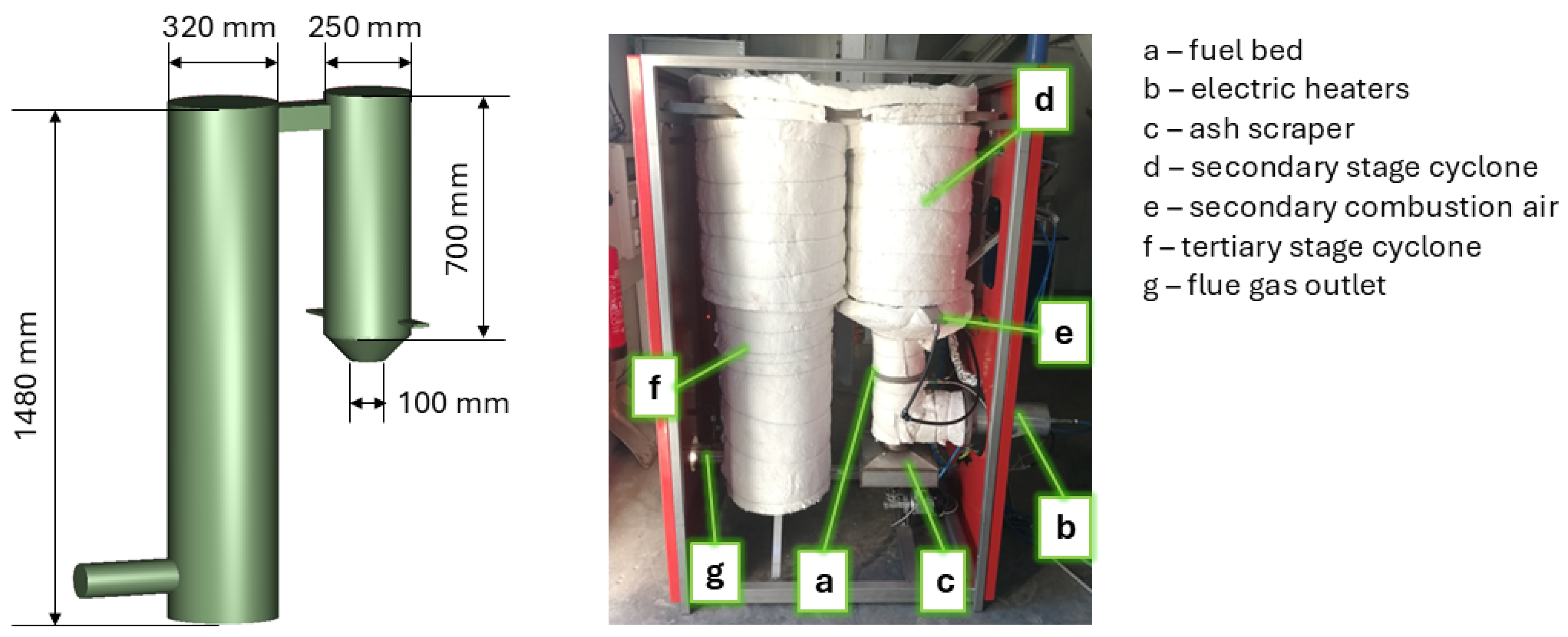
Various design solutions were adapted to provide a pilot system where the listed challenges are addressed. The maximal fuel thermal power is 15 kW, where the combined effects of low calorific value and sludge morphology already require precise combustion process control. Preheating of primary combustion air is employed to ensure sufficiently high temperatures of volatiles emitted from the bed, while the bed temperature is monitored to omit ash melting, which could trap combustible matter. Three 2 kW heaters are utilized for preheating, which allows sufficient flexibility for analyzing and evaluating different combustion conditions. To ensure efficient heat recovery from the remaining ash, and to utilize this heat for fresh fuel drying and devolatilization, a counter-flow bed with vertical movement and suitably long sludge retention times was designed. In order to ensure efficient freeboard volume utilization, a swirl-guided flow, introduced through the injection of secondary air, is used to reduce the wall-induced cold spots and ensure a high degree of mixing while maintaining a highly uniform axial velocity profile.
The devised pilot small-scale system is shown in Figure 3, with the presentation of the constructed and installed system on the operating site, to which the 3D CAD negative of the gas phase domain is added. The fixed bed (a) with a counter-current flow of sludge and primary combustion air ensures reintroduction of the heat that remains in the ash. The primary air is delivered to it after being preheated to the desired temperature by electric heaters at position (b). The ash formed in the fuel bed is removed by the ash scraper (c) when a sufficiently thick layer of it is established at the bottom of the fuel bed. In-bed temperature measurement serves as the indicator of this. The primary combustion stage extends from the fuel bed to the secondary combustion stage cyclone (d), which is conditioned with secondary combustion air supply (e) through two ports on the opposite ends and at a certain misalignment. This allows for the cyclone flow to form and imposes efficient mixing due to the simultaneous introduction of the shear forces. The tertiary stage cyclone (f) ensures suitably long residence times of combustion products before the outlet at (g). Optionally, this cyclone is equipped with supportive external fuel to meet the required temperature levels in the case of low fuel quality. The fuel bed connects to the secondary stage cyclone via the conical part. The walls are insulated with 50–100 mm of ceramic wool. The placement and dimensions of the system components allow it to be highly mobile, as the system can be placed on a car trailer and transported across building doors.
The system is equipped with control and supportive systems, which are illustrated with the control scheme in Figure 4. The control system monitors and controls the main operating parameters, which are fully adjustable through the supportive systems. These parameters include the primary and secondary combustion air mass flow, primary air preheating, fuel feeding rate, and end-ash removal rate. While the last parameter is only defined during the system operation, other parameters are set on the basis of preliminary experimental investigation. The fuel feeding system with a volume of 125 cm3 relies on a pneumatically operated sliding gate valve and adjustable dosing interval for fuel mass flow control to set the desired thermal power. This allows us to narrow down the choices of suitable operating conditions for certain sludge prior to its application. The operation of the fuel feeding system and the ash scraper determines the sludge retention time on the grate, alongside the sludge volume contraction. Sludge retention time is ensured to amount to at least 300 s, while on average, considerably longer retention times are intended, allowing for the efficient heat recovery from the ash. To provide complete control of the operating parameters, the primary and secondary air mass flows are measured with thermal flow meters (3% accuracy), while the temperature is measured at different positions with shielded Class 1 K-type thermocouples. These have a standard tolerance of ±3.2 K in the measured temperature range. Possible additional measurement errors could occur due to the radiative and conduction effects. The thermocouples are sheathed and protrude 150 mm into the system. It is hence estimated that the conductive heat losses through the sheath and possible radiative heat gains from the flame front are largely compensated. The locations of the measuring equipment are also indicated in Figure 4. The measuring equipment was calibrated prior to the experiments offline, following the manufacturer’s instructions. The dedicated stand-alone control system can support fully autonomous operation at a desired location.
The main experimental data, gained with the devised system and used to validate the model, is presented with the temperatures, measured at positions depicted as T1 and T2 in Figure 4. The two temperatures provide spatially distributed information on the combustion evolution across the secondary combustion stage cyclone, where the main combustion of the emitted volatiles from the fuel bed is expected to occur. Capturing the measured temperatures at these two locations in simulations would thus directly confirm the proposed model as capable of correctly predicting the combustion evolution of a complex fuel in a spatially confined volume.
The system in the presented form does not include flue gas treatment equipment. The reason for this is the need to first confirm whether the system can achieve suitable temperatures and sustainable operation with sludge as the only fuel. Additionally, it is expected that the presence of two cyclones positively affects the particulate matter emissions. The ability to control primary air mass flow, and hence the temperatures and velocity conditions in the fuel bed, is also important in this regard. Furthermore, the control over primary and secondary air mass flows and their temperatures provides the ability to control the highest temperatures in the system, effectively enabling control over nitrous oxide emissions.

2.4. Numerical Setup

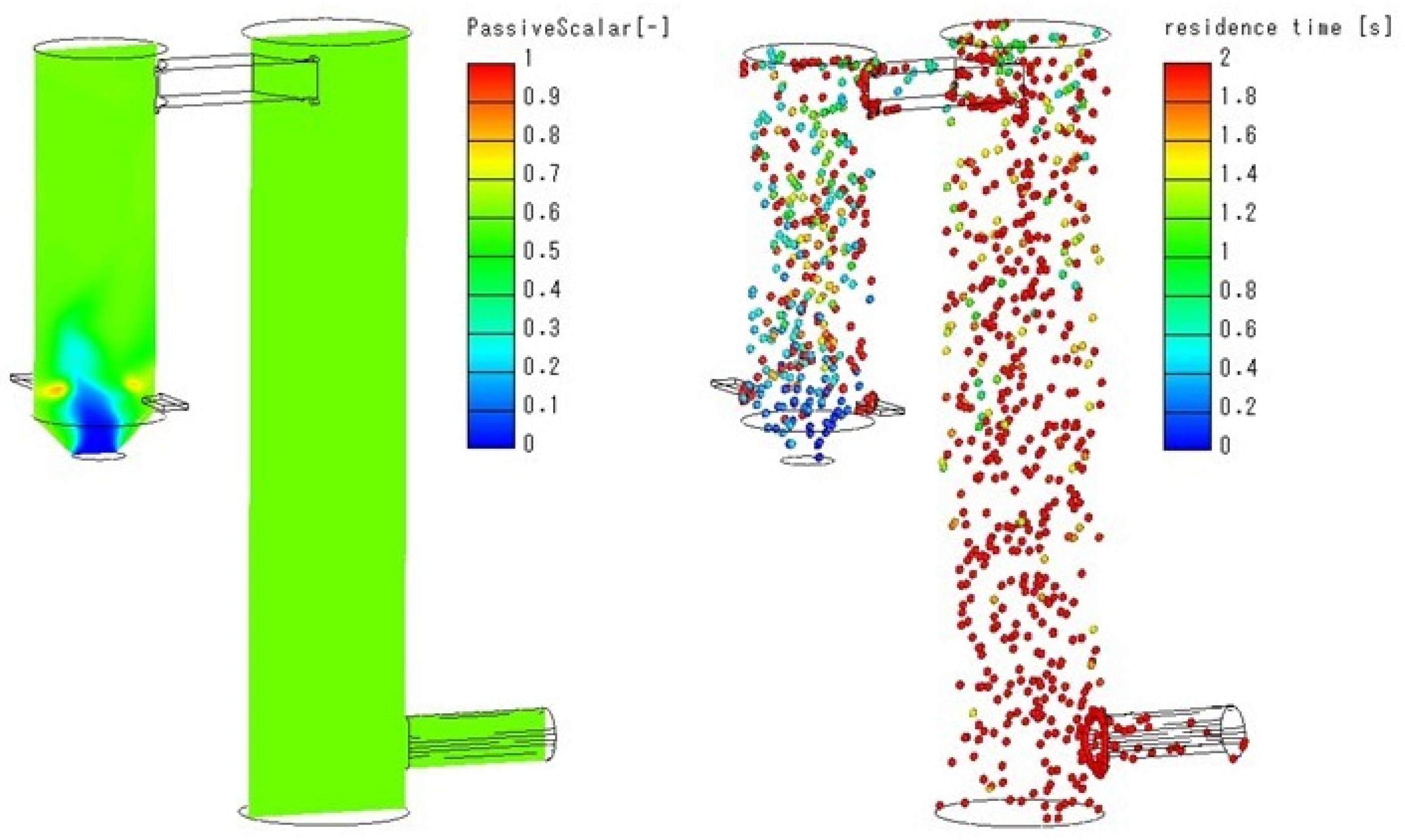
The simulations were performed in commercial CFD software AVL Fire [53]. The simulation setup is described in the following subsections. In addition to the combustion simulations, this work also includes the preliminary non-reactive flow simulations’ results. These were applied in the development of the pilot small-scale system and helped to determine if sufficient flow mixing and gas residence times are achieved. Therefore, the preliminary simulations provide an additional insight into the underlying properties of the small-scale system and not into the capabilities of the model. Hence, their numerical setup and results are provided in Appendix A.

2.4.1. Computational Domain, Boundary Conditions, and Applied Mesh

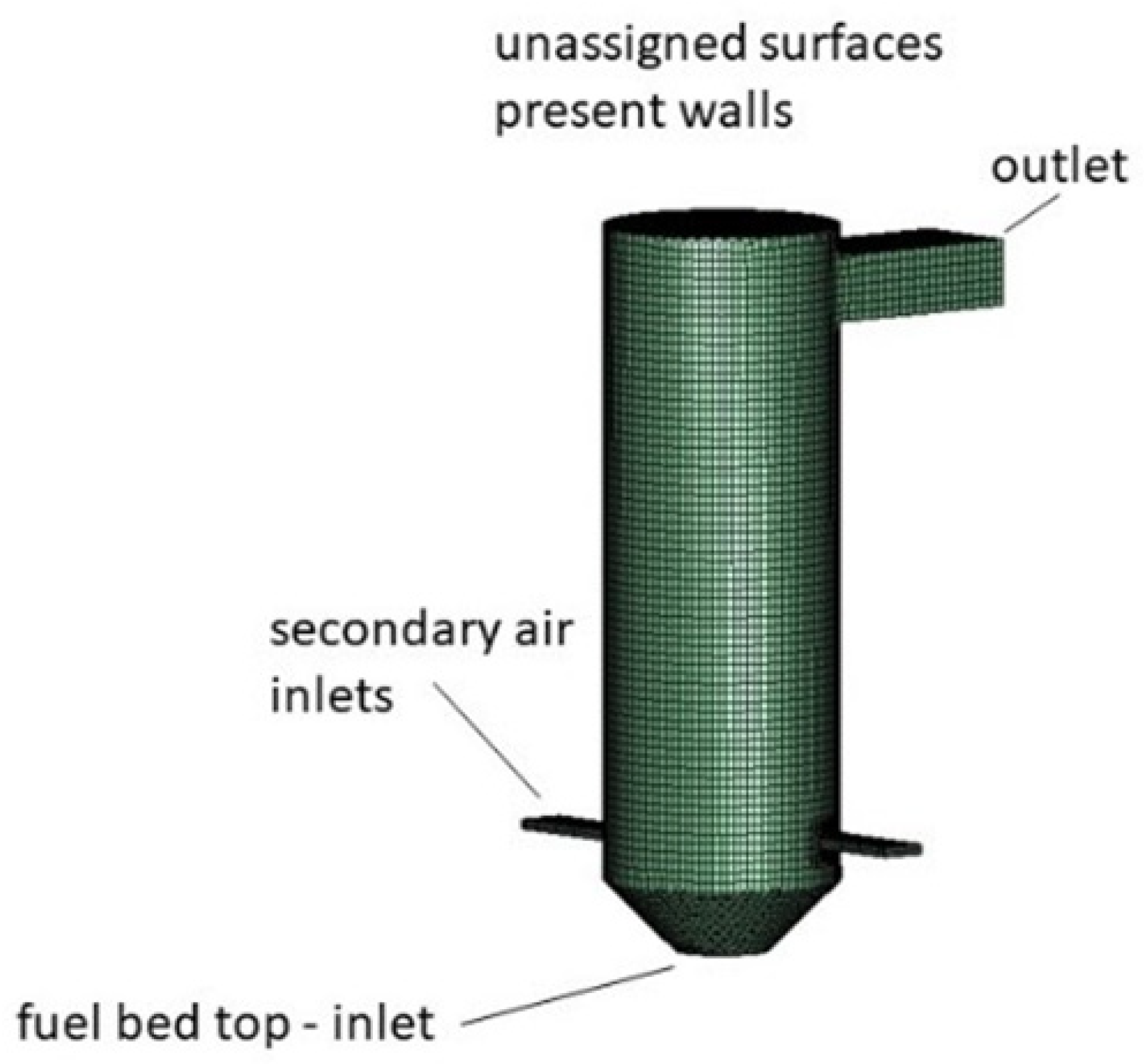
The applied computational domain includes only the secondary stage cyclone since combustion is completed within it. Inclusion of the tertiary stage cyclone would thus solely increase computational costs while no additional insight into combustion phenomena would be obtained. The domain is shown in Figure 5, with indicated boundaries.
The applied boundary conditions are defined in Table 5. Importantly, the wall boundary conditions enable the inclusion of heat losses, which are modeled via the thermal resistance of the walls and conduction to the surroundings. The secondary air inlets are defined with the case-specific mass flow of air at a certain temperature. The fuel bed inlet features separate inlet surfaces for surrogates and remaining air. Separate inlets proved to provide the most realistic description of the conditions in previous studies [11,54]. Fuel bed and secondary air inlets are defined according to mass flow, composition, and temperature of their gases.

2.4.2. Applied Flow Models and Discretization Schemes

The performed simulations apply flow models and discretization schemes summarized in Table 6. While more information on applied models can be found in [53], the following paragraphs provide a description of the turbulence model and of the surrogate-based combustion model inclusion in the performed 3D CFD simulations.
The pilot system simulations require the inclusion of turbulence and turbulence–chemistry interaction models due to the presence of turbulent flow. Turbulence is modeled with the k-ζ-f model [55]. The model includes three transport equations. Apart from solving the transport equations for the turbulent kinetic energy k and turbulent kinetic energy dissipation rate ε , the model also solves the transport equation for the velocity scale ratio ζ . The k-ζ-f model is thus a three-equation turbulence model. The ratio ζ is defined as
ζ = v 2 ¯ k .
The v 2 ¯ in Equation (1) presents the wall normal velocity fluctuation, through which the turbulent transport damping close to the walls can be described. This damping presents anisotropic turbulence effects, which are modeled with an elliptic relaxation function f [55]. The model applies the wall normal velocity fluctuation to determine the eddy viscosity ν t , as per equation
ν t = C μ ζ k 2 ε .
The C μ in Equation (2) has the value C μ = 0.22 . The eddy viscosity thus inherently accounts for the anisotropic turbulence effects at the walls and improves their description. The model was chosen for the simulations in this work as this ability is highly important in the case of the considered small-scale pilot system, where secondary air inlets impose cyclone flow.
The surrogate-based combustion model applies the afore determined surrogates and describes their combustion with the use of a reduced reaction mechanism. The mechanism is provided in CHEMKIN II format and introduced to 3D CFD simulations with AVL Fire through the use of the Internal Chemistry Interpreter (ICI). The interpreter reads the reaction equations from the provided mechanism and defines the rate of production r ˙ for a certain species n using the following equation:
r ˙ n = i = 1 I ν n , i · q ˙ i .
The ν n , i presents the stoichiometric coefficient of species n in reaction i as
ν n , i = ν n , i ν n , i ,
where ν n , i and ν n , i denote the coefficient value for species n in reaction i on the side of products or reactants, respectively. The reaction rate q ˙ i of reaction i is defined with the difference in the forward and backward reaction rates, written as
q ˙ i = k f , i · n = 1 N c n ν n , i k r , i · n = 1 N c n ν n , i .
The c n in Equation (5) denotes the molar concentration of species n , while k f , i and k r , i present forward and backward reaction rate constants, respectively. The forward reaction rate constant is defined according to Arrhenius’ temperature dependence:
k f , i = A i T β i exp E i R T .
The A i is the pre-exponential factor, β i is the temperature exponent, and E i is the activation energy of the reaction i . The backward reaction rate constant k r , i is defined from the forward reaction rate constant k f , i through the division of k f , i with the i t h reaction equilibrium constant K C , i . The values for A i , β i , and E i are provided for all reactions in the reaction mechanism that is introduced into AVL Fire through the ICI. The definition of the equilibrium constants K C , i for reaction i relies on the definition of reactants’ and products’ standard state entropies and standard enthalpies of formation. For this, the ICI requires data about thermodynamic properties, which is supplied in the form of NASA polynomials in a separate file (thermdat file). Obtaining the rate of production r ˙ definition for all the species then allows the interpreter to define the source terms for the species transport equations and the energy equation. In turn, these equations determine the concentration and temperature fields. As the whole domain is considered to be a reactive zone, and the solution for the concentration field is computationally intensive, the multi-zone speed-up option is applied. This gathers areas with similar conditions in order to enable faster simulations.
Finally, it should be added that the species transport equations require information about the species’ transport properties. These are also supplied by NASA polynomials in a separate file (trandat file). The species transport and the chemical kinetics description must also account for the turbulence–chemistry interactions. These are modeled with the Kong model [56], due to its suitability to be used directly with the detailed or reduced reaction mechanisms [53], applied by the combustion model through the ICI.

2.4.3. Mesh Independence Study Setup

The mesh independence study was performed for the computational domain, shown in Figure 5, and flow conditions that mimic those of the experimentally observed combustion in the small-scale system. Except for the use of the Steady Combustion Model (SCM), the mesh independence study features the same numerical setup as simulations with the surrogate-based combustion model.
The SCM is applied as it allows for an efficient mesh independence study in reactive flow conditions. Namely, the use of detailed reaction mechanisms would be highly demanding on the finest considered meshes, especially since the simulations with these mechanisms must be transient. The SCM, on the contrary, allows for a simple combustion prediction through the fuel consumption rate r , defined with Equation (7).
r = ρ · k · Y f u v 1 Y O 2 v 2 .
The ρ is the density, k is the reaction rate constant (always greater than 0), Y f u is the fuel mass fraction, and Y O 2 is the oxygen mass fraction. The exponents v 1 and v 2 determine the reaction order. The model always predicts combustion if fuel and oxygen are present in a computational cell. Consequently, it also leads to a higher heat release than combustion models that rely on detailed reaction mechanisms. As a result, the mesh independence analysis includes simulations where higher temperature gradients are present than those expected with the surrogate-based combustion model. The mesh, determined as suitable for use with the SCM, will hence also be suitable for use with the surrogate-based combustion model.

3. Results and Discussion

The experimentally obtained data is presented first, as it provides the basis for the presentation of combustion simulations with the surrogate-based combustion model. Then, the mesh independence study results and the applied mesh are presented to introduce the following simulations with the surrogate-based combustion model. The comparison of these simulations with experimentally observed combustion conditions is used to validate the model and its tailored surrogates as suitable for providing accurate combustion simulations in small-scale systems. Validation is followed by the application of combustion simulations in the parametric analysis, where cases of various air–fuel ratios, fuel moisture presence, bed temperature, and applied thermal power are studied to define system operation control strategy guidelines.

3.1. Experimental Measurements of the Pilot Small-Scale System Performance

Continuous operation of the system was observed in the performed experiments. The first goal was to confirm the system design as appropriate to ensure suitable, self-sustained, and well-controlled combustion. The results from such combustion are then used for model validation. The applied operating conditions were set on the basis of the performed SS combustion analysis in the experimental unit. The sludge featured 13.5% moisture and 33% ash, while the rest is presented by combustible matter. Its HHV was measured at 12.25 MJ/kg. The mass flow of sludge was set as 2.93 kg/h to provide continuous system operation at 10 kW of thermal power. Conditions in the fuel bed are set with relatively low air mass flow to impose fuel-rich conditions with gasification. This is then combined with the complete combustion of emitted volatiles in the freeboard through the introduction of a suitably high amount of secondary combustion air. The primary air was preheated to 413 K, while the secondary air was introduced at ambient temperature. The applied operating conditions are gathered in Table 7.
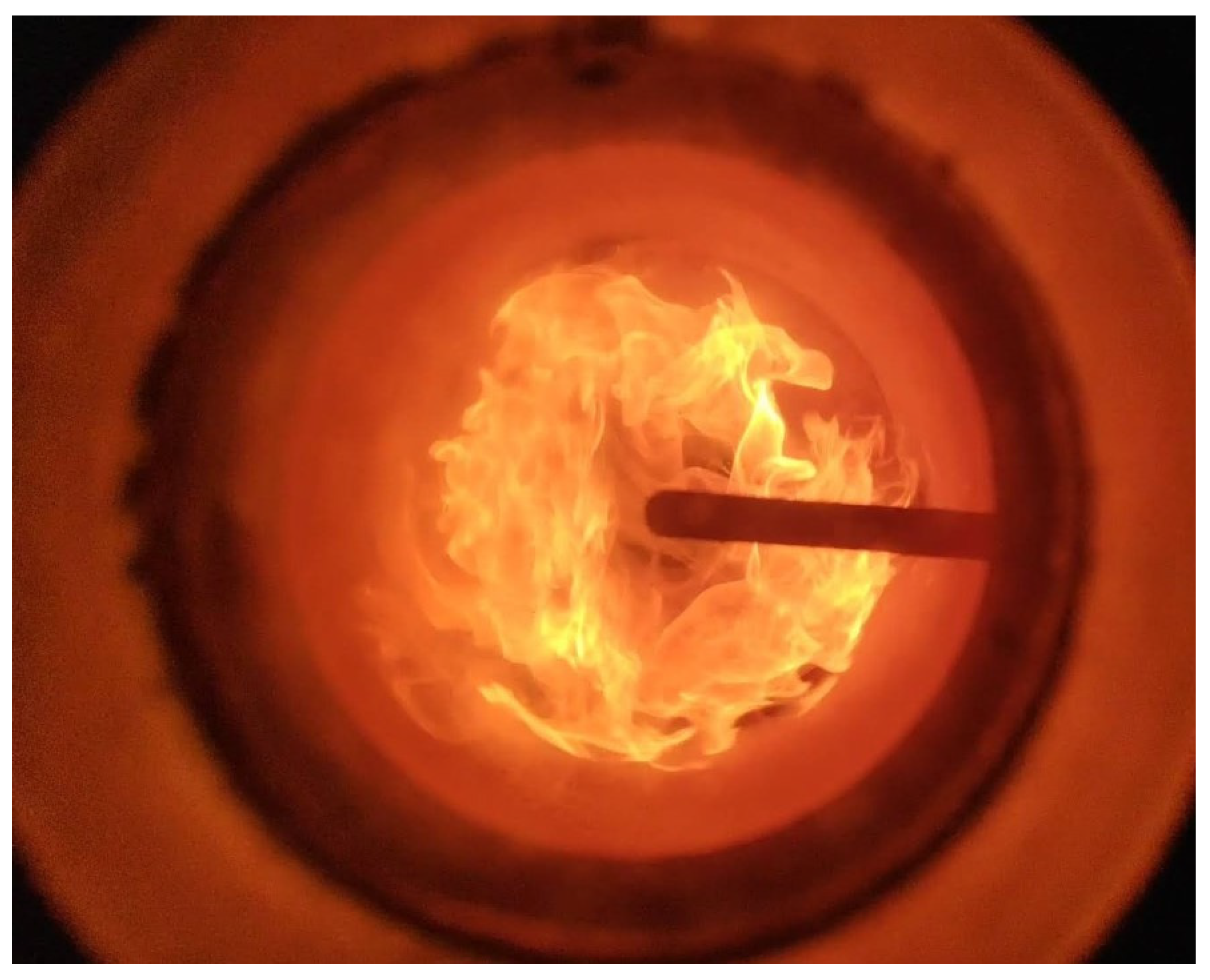
The system operation was initiated by the combustion of wood pellets. The pellets were replaced with sewage sludge after 30 min. This brought the system to operating temperature, which enabled a seamless switch to sludge incineration. The results obtained from several hours of continuous system operation, during which all of the available sludge was successfully incinerated, are presented in Table 8. The second column presents the average temperature, measured at a certain position, to which the standard deviation, defined at that position, is added. The last column provides the combined measurement uncertainty, which is obtained by combining the sensor’s standard tolerance (±3.2 K) and standard deviation. Figure 6 depicts the secondary combustion zone in operation as visible through the view port.
The system achieves the required flue gas temperatures and provides enough heat flow to the fuel bed to ensure drying of the remaining moisture in the sludge and combustion of its organic content. The high total amount of supplied air leads to a high amount of combustion products with a sufficiently high temperature to provide the required preheating of the primary air and additional drying of the sludge. Results confirm the suitability of the system for performing small-scale sludge incineration. Therefore, the results also point to the suitability of preliminary non-reactive flow simulations, which were performed during the development of the small-scale system and are provided in Appendix A. Finally, the system and the obtained results were also considered suitable for validating the innovative surrogate-based combustion model and the tailored surrogates, defined with it.

3.2. The Applied Computational Mesh

The mesh independence study applies the boundary conditions that mimic the experimentally observed conditions. Methane is selected as the fuel because it enables a straightforward application of the SCM. Crucially, it allows for larger imposed temperature gradients, which further strengthen the assessment of suitable mesh resolution. The mass flow of methane is defined to equal 10 kW of thermal power, which is the thermal power provided by the SS during the performed experimental measurement. Methane is injected into the domain through the positions on the fuel bed inlet that are used for surrogate injections. The remaining fuel bed inlet surface is used to introduce inert gas in the form of methane complete combustion products. The inert gas mass flow is chosen to equal the mass flow of primary air in the performed experimental measurement. Combustion air is introduced into the domain through secondary air inlets with a mass flow slightly higher than the mass flow at these inlets in the experiment. The combined mass flow from the fuel bed and secondary air inlets is, finally, slightly higher than the total mass flow in the experiment. The imposed temperatures at the inlets follow the temperatures applied in the simulations with the surrogate-based combustion model. The mass flows, their composition, and their temperatures at different inlets are listed in Table 9.
Three meshes were considered in the mesh independence study, featuring 63,000, 164,500, and 500,000 elements. The meshes are predominantly hexahedral and locally refined near the secondary air inlets and the fuel bed. The largest cells have 9 mm long sides. The mesh independence study results are presented in Figure 7 and Figure 8. Figure 7 depicts the temperature contours obtained with the three meshes at the mid-cut of the computational domain. The graph in Figure 8 reports the temperature profiles obtained in the simulations with the three meshes at a distance of 12 cm from the secondary air inlets, which is still in the reactive zone. Results show a good correspondence between the three meshes. All of the main combustion characteristics, from the reactive zone shape to the temperature profile evolution across the furnace, are captured already on the coarsest mesh. Combined with the higher demand for mesh quality that is imposed by higher temperature gradients, generated with the SCM, the coarse mesh with 63,000 elements was chosen as suitable for this study. The mesh is already shown in Figure 5, where it is used to depict the geometry of the computational domain. Importantly, the use of this mesh allows for considerably less demanding simulations with the surrogate-based combustion model. In return, a higher number of simulations can be performed on a personal computer, and different operating conditions can be analyzed.

3.3. Surrogate-Based Combustion Model Validation

Combustion simulations require the definition of the inlet temperature and surrogate composition. The inlet temperature is defined in the first subsection. Then, surrogate composition is presented through the surrogate tailoring process, introduced with the innovative surrogate-based combustion model. The tailored surrogates are based on the surrogates defined in Table 3. Finally, the results of simulations are reported and compared against the experimentally measured values to provide validation of the surrogate-based model and the surrogates defined with it.

3.3.1. The Inlet Temperature

The inlet temperature was set following the estimation that the temperature of the gases at the fuel bed top falls between the measured in-bed temperature of sludge after combustion and the primary air temperature. The value of 918 K was defined considering the energy balance, which accounts for the temperature at the end of the secondary stage cyclone (freeboard), the heat losses across the walls, and the energy introduced with the sludge, primary and secondary combustion air. The heat losses were calculated using thermal resistance and convection coefficients for the walls, which also served to set the boundary conditions listed in Table 5. The results from simulations confirmed the chosen temperature as suitable.

3.3.2. Surrogate Composition Tailoring

Surrogate tailoring is performed in two steps, described in Section 2.2. First, the general fuel formula and mass flow of fuel are determined. The general fuel formula is due to the continuous combustion in the pilot system defined as equal to general formula for fresh sludge, CH1.8O0.5. The mass flow of fuel with this formula is defined as the product of the sludge mass flow to the pilot system and its volatile mass fraction. Applying the values reported in Section 3.2, the mass flow of fuel equals 1.568 kg/h.
Then, the initial surrogates, stated in Table 3, are tailored to the pilot small-scale system fuel bed conditions by assuming that the majority of oxygen from air in the fuel bed reacts with the sludge to form CO. The remaining part of the oxygen forms CO2, while the mass fractions of other surrogate species are altered to ensure mass balance. The procedure is iteratively repeated until a surrogate is found that resembles the mass and energy fractions of species in the initial surrogate. The defined tailored surrogate composition is given in Table 10. A comparison of this composition with the composition in Table 3 shows that both the mass and energy fractions of combustible species are aligned. This is particularly crucial for hydrogen and methane as their chemical energy fractions were identified to be key to the suitable capturing of underlying chemical kinetics in combustion of SS decomposition products [11].
The tailored surrogate composition ensures the mass balance. The tailoring process also observed surrogate calorific energy as this should be lower than the energy introduced into the system with the sludge. Additionally, the energy balance check was performed for the tailored surrogate by applying the defined inlet temperature, known temperatures in the system, and the mass flows of the surrogate, accompanied by water vapor from the moisture and the remaining combustion air. While 8.26 kW of calorific energy is required to achieve the measured end gas temperature, the calorific energy provided by the defined surrogate equals 8.42 kW. This difference is sufficiently small that no further alignment of the surrogate composition was deemed necessary. The difference to 10 kW is presented with gasification and combustion reactions in the bed.

3.3.3. Results and Validation of 3D CFD Simulations

Simulations with the tailored surrogate composition capture 10 s of combustion, which exhibits a steady-state nature. The results are shown in Figure 9 in the form of cross sections for CO mass fraction and temperature fields. The iso-surface, defined with the OH radical mass fraction of 5 × 10⁻⁵, is added to illustrate the reactive zone shape and length. Local temperature values are plotted on it. In addition to the iso-surface of the OH radical, Figure 10 presents cross sections for mass fractions of the O and CH3 radicals and of the C2H2. These and many other concentration fields are obtained as a result of the proposed model, enabling the use of the specifically tailored surrogates and reduced reaction mechanism. The two radicals provide additional information about the reaction zone, while the C2H2 allows for an insight into the potential soot formation. Validation is provided through a comparison of temperatures at the two measuring positions in the secondary stage cyclone with the experimentally obtained average temperature values. The temperatures are listed in Table 11.
The results show that simulations capture the experimentally observed combustion well. The simulated temperatures at both observed positions only slightly and by nearly the same amount exceed the average measured values (21 and 30 K). These differences could be the result of the numerical errors that originate from the discretization and applied flow models. An additional source of discrepancies can be in the discrepancies between the set boundary conditions, such as wall thermal resistance and emissivity, and the actual system properties. Crucially, however, the noted differences between the simulated and measured values are considered to be very small, as the differences reported in the literature on waste incineration simulations are often higher. For instance, differences often in excess of 50 K are reported in [24], and the same applies for [18]. Differences lower than 10 K are, on the other hand, noted for sludge combustion in [28]. However, the latter is a specific case, where the simulations describe an electrically heated furnace, kept at temperatures that are close to the temperatures of sludge combustion. Furthermore, the temperature difference between the two observed positions in here presented simulations is also nearly the same as in the experiment (60 compared to 51 K). The higher temperature is also correspondingly present closer to the secondary air injection. Finally, the close match between the experimental and simulated temperatures is especially important as the first measuring position resides within the reaction zone, while the second is located after it. The results thus confirm that the simulations correctly capture combustion evolution in the pilot system. The results therefore affirm the innovative model and its tailored surrogates as valid for describing sludge combustion in small-scale systems. The simulations were also concluded in less than 20 h on a personal computer with an i-7 6800K processor using five cores. Consequently, the combustion model is confirmed as a low-cost, yet practical tool for achieving detailed 3D CFD prediction of SS combustion in small-scale systems.
The plots in Figure 9 and Figure 10 also show that combustion completes in the first half of the secondary stage cyclone, immediately after the secondary air inlets. The temperature field shows quick homogenization after combustion due to efficient mixing provided by the secondary air. The shape of the CO mass fraction field complements these results, as well as the shape of the reactive zone presented with the OH radical iso-surface. The O and CH3 radical cross sections correlate with the OH radical iso-surface. The O radical provides additional insight into the flame front location, as its presence typically peaks at zones that have lean to stoichiometric conditions and thus allow for high-temperature oxidation. The CH3 radical, on the contrary, points to the fuel-rich zones with strong pyrolysis or hydrocarbon fragmentation that reside close to the flame front and thus feed highly reactive species into it. Combined, the O and CH3 radicals depict the flame front formation process. The C2H2 cross section, shown in Figure 10, points to the potential for soot formation due to C2H2 being a crucial soot formation precursor. As is visible, the location of the highest C2H2 presence correlates with the position of high CH3 radical presence in the middle of the cyclone. However, C2H2 presence quickly diminishes across the flame front, which is aided by the efficient mixing and high temperatures after the secondary air injection. It is consequently assumed that imposed flow conditions effectively prevent soot formation. Combined, the depicted cross sections provide a detailed illustration of how the reactive zone evolves from the fuel bed onwards, passing the secondary air inlets and finally reaching a position of complete combustion. The ability to describe concentration fields of different species, also intermediate ones, is beyond the state-of-the-art feature of the devised surrogate-based combustion model. By this, the model allows for high-fidelity coupling between the flow and concentration fields, which offers unprecedented insight into the reaction zone development.

3.4. Parametric Analysis for Definition of System Operation Control Strategies

Small-scale systems are exposed to highly variable operating conditions due to the variable moisture content and calorific value of the sludge. The validated surrogate-based combustion model provides the ability for the 3D CFD-based optimization of the system operation under different conditions due to its computationally efficient and detailed reactive zone presentation. To depict this ability, parametric analysis was performed, where system responses are observed for the variable secondary air injection, fuel moisture level, fuel bed temperature, and introduced thermal power. The chosen parameters present the main system operating conditions, which can also be intentionally adapted to optimize the incineration process. The following subsections provide information on how the model can help in defining the control strategies that improve system operation through the adaptation of the considered parameters. The experimentally observed conditions present the reference case, while all simulations apply the validated surrogate.

3.4.1. Variable Secondary Combustion Air Mass Flow

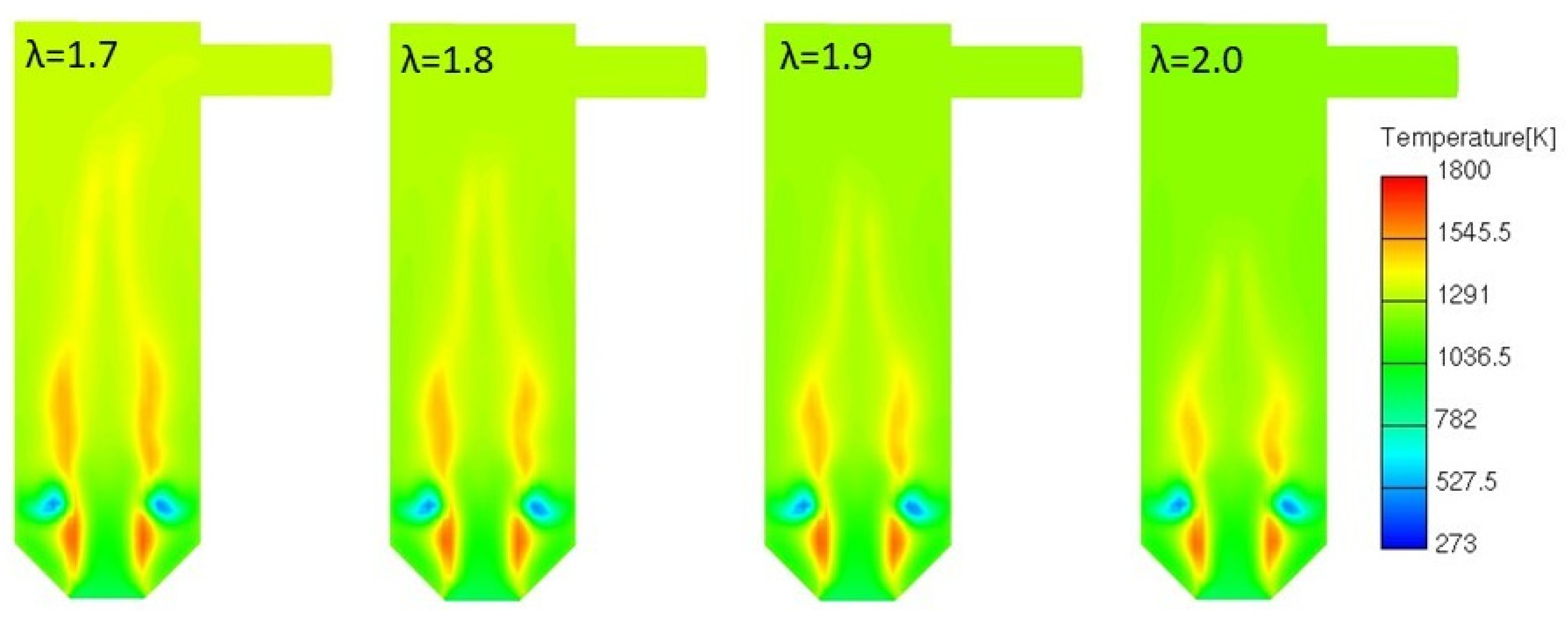
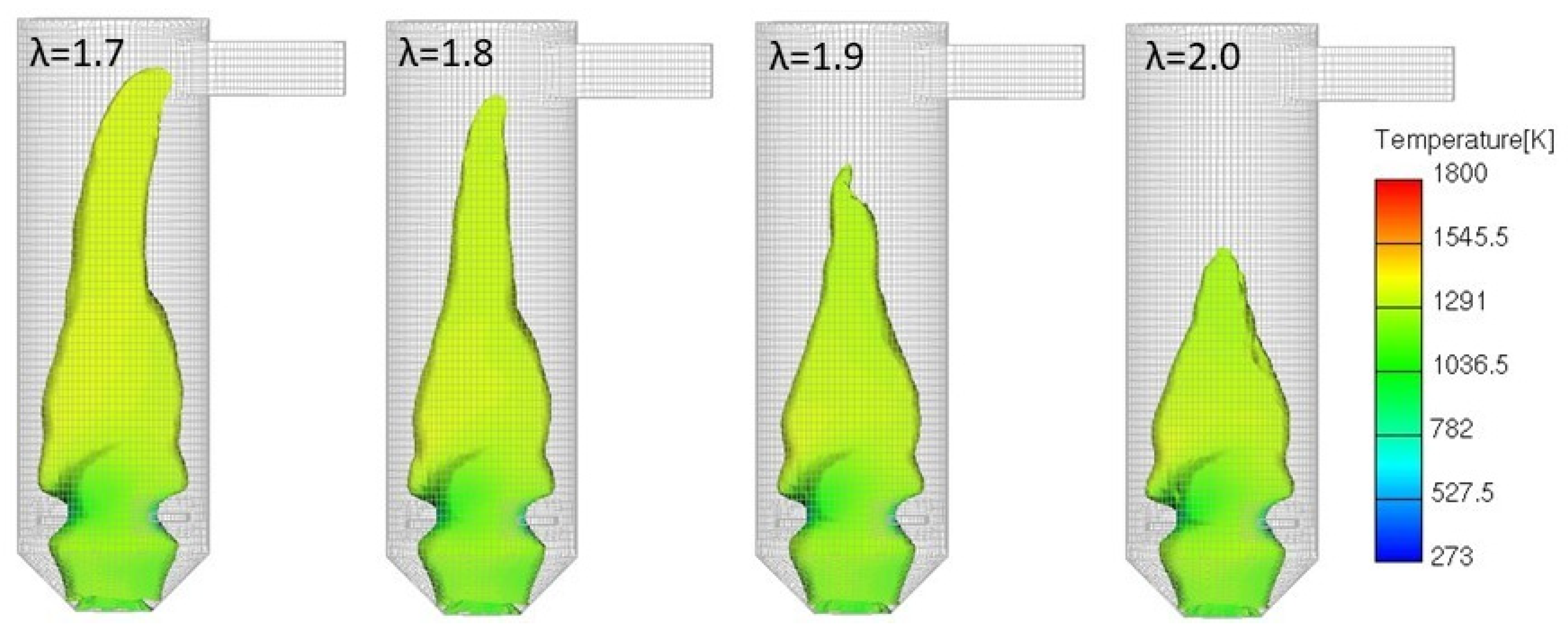
The validated simulations feature 1.568 kg/h of mass flow of combustible matter with the general fuel formula CH1.8O0.5. With a total air mass flow of 22.84 kg/h (Table 7), this imposes lean conditions in the freeboard, with a value of λ = 2.0. To determine how the combustion varies with secondary air flow injection and to define how this can be used for combustion optimization, the secondary air mass flow was gradually lowered to achieve λ = 1.5. The analysis included temperature field results, reaction zone length and flow field homogeneity, presented with the temperature cross sections, iso-surfaces of the OH radical mass fraction, and with cross sections of the O radical and C2H2 mass fraction. The results are given in series in Figure 11, Figure 12, Figure 13 and Figure 14 for values from λ = 1.5 to λ = 2.0, respectively.
All presented results point to the same conclusions. The lower λ values lead to an expected increase in the highest temperatures due to the lower air mass flow. The reaction zone also becomes considerably longer with a lower secondary air flow. On the contrary, increasing the secondary air flow shortens the reactive zone. Although the opposite would be expected, results depict that the increased secondary air flow condenses the reactive zone, exposing the importance of maintaining a proper balance between reaction rates and turbulence-induced flow mixing. This points to combustion being considerably affected by local mass transfer phenomena in the flow, leading to slower combustion and a visibly less uniform flow field in the axial direction at lower λ values. The reactive zone length is thus affected by the imposed flow mixing, although all considered conditions feature a surplus of combustion air.
The results also show that lower λ values should be avoided. The first reason is in the reaction zone stretching to the connecting channel between the cyclones. The OH radical iso-surfaces and O radical cross sections also show that the flame front enters into this channel at the lowest considered λ value. The lowest lambda value can, therefore, also cause overheating near the connecting channel. Observation of the C2H2 cross sections reveals the second reason for avoiding the low λ values. The C2H2 mass fraction and the size of its presence zone increase with the lowering of the λ value, which points to the increased soot formation potential. In addition to this, the weaker flow mixing at lower λ values also leads to a longer exposure of gases near the reaction zone to higher temperatures. Consequently, an increase in NOx emissions is also possible. Following the obtained results and the need to impose a well-controlled reactive zone in terms of its length and temperature, the conditions at λ = 1.8 are chosen as suitable in this particular study. At the imposed fuel bed temperature, mass flow, and fuel properties, the value of λ = 1.8 provides a higher combustion products’ temperature than higher λ values. Furthermore, the reactive zone is still retained well within the secondary stage cyclone, with the temperature field reaching high homogeneity close to its half-height point. Consequently, there is a lower possibility of soot formation. Due to the temperature not reaching as high values over a considerable span of the cyclone as in the case of lower λ values, there is also a lower possibility of NOx emissions.

3.4.2. Impact of Higher SS Moisture Fraction

The goal of this analysis was to determine whether an increased moisture presence affects combustion in terms of altering the temperature and reaction zone length, as well as to define the potentially necessary adjustment of operating conditions. The impact on combustion is thus considered solely for the gas phase domain. The reasons are the long retention times of the sludge on the grate (approx. 800 s in the observed conditions). Thus, the heat entrapped in the remaining ash and the primary air preheating can be applied to provide additional sludge drying.
The increased moisture content is described with surrogate composition, which features an increase in the H2O fraction. A vapor mass flow of 1.05 kg/h was imposed instead of the previous 0.39 kg/h, introducing a considerable change. The simulations also feature variable secondary air mass flow to provide λ values between 1.7 and 2.0. The results are presented in Figure 15 and Figure 16 with a comparison of the temperature cross sections and OH iso-surfaces. Combining the results from these simulations with those from the previous section allows for the combined effect analysis of two parameters, the moisture fraction and variable secondary air injection.
The increased moisture presence results in a considerably altered reaction zone and temperature field. The temperatures are expectedly lower since water vapor presents an additional inert mass. This additional mass also increases the inertia of the flow from the bed, resulting in lower mixing efficiency and thus a longer reaction zone. It can be concluded that an increased moisture presence has the same impact on the reaction zone length as lower λ.
The secondary air mass flow can be slightly increased to optimize the reaction zone length in the case of increased moisture. A comparison of the results in Figure 12 and Figure 16 shows that the value of λ = 2.0 provides the same reaction zone length at a considered higher moisture presence as the use of λ = 1.8 in the previous section, where lower moisture presence is considered. The optimized combustion conditions are thus in this case achieved at a higher λ value, showing that the secondary air mass flow can be effectively used to control combustion. Although a lower air mass flow would be intuitively suggested to counter higher moisture presence with higher flue gas temperature, it is important to note that, following the considerable presence of volatile matter in the sludge, the reaction zone in the gas phase importantly depends on the flow mixing.
The dependence of the reaction zone on flow mixing, exerted through observed variations in λ and moisture presence, leads to another important observation. Both the increased moisture presence and lower λ through lower secondary air injections increase the ratio between the inertia of the flow from the fuel bed and from the secondary inlets. A drop in this ratio leads to a shorter reaction zone, while an increase has the opposite effect. The impact of the changes in this ratio on mixing and thus the reaction zone is also seen in the following studies.

3.4.3. Lower Fuel Bed Temperature

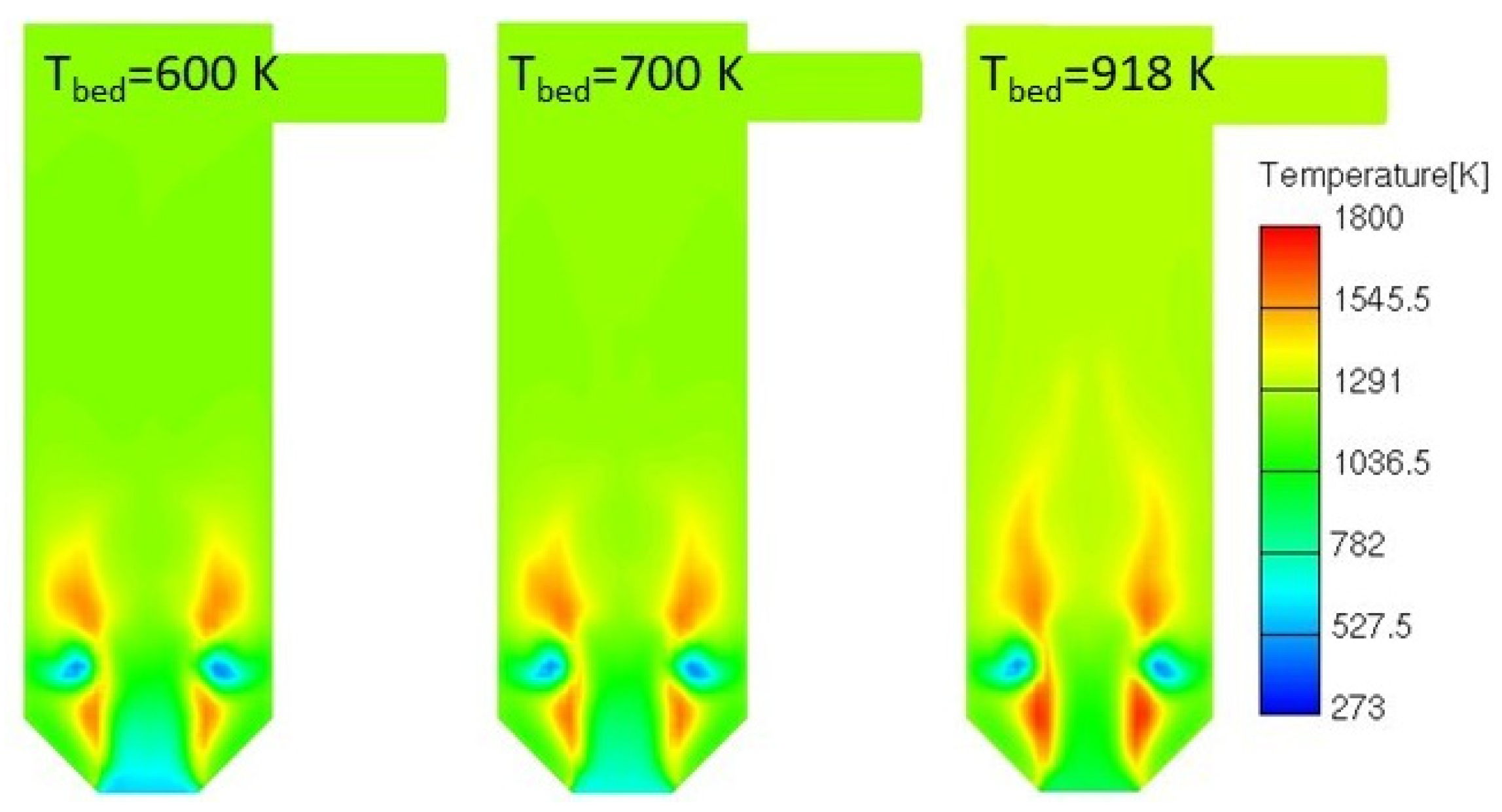
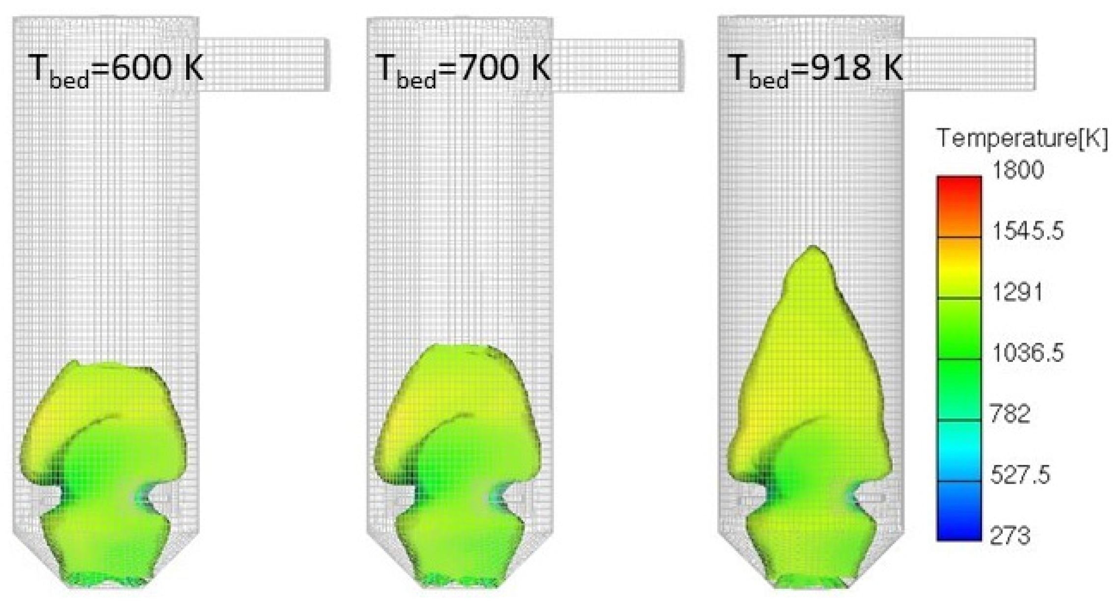
Maintaining suitable combustion in the freeboard can be challenging if bed temperatures decrease. Thus, two lower bed temperatures, 700 and 600 K, were observed in addition to the reference one (918 K). The applied thermal power was the same as before (8.42 kW), while λ equals 1.8, as this presents the optimal conditions for the reference case. The lowest bed temperature was chosen with the goal of maintaining a suitably high temperature of combustion products (higher than 1123 K). The results are shown in Figure 17 and Figure 18 with the comparison of temperature cross sections and OH iso-surfaces.
While the final temperature expectedly decreases with decreasing bed temperature, it is important to note that the reaction zone also becomes shorter. The reason is again attributed to the ratio between the inertia of the flow from the fuel bed and the secondary air injections. This ratio decreases with the decrease in fuel bed temperature, as this leads to lower density and thus lower gas velocities from this inlet. The secondary air injections are thus able to provide improved flow mixing at the same mass flows. It follows that while a lower bed temperature can have an adverse impact on the temperature of combustion products, it can also be used to affect flow mixing and, by this, the reaction zone length through the lowering of the discussed inertia ratio.

3.4.4. Variable Thermal Power

The analysis of the impacts caused by the variable thermal power relates to the definition of the useful system operation range. While reference conditions are set at 10 kW, additional simulations at 5, 7.5, and 15 kW thermal power were conducted. The surrogate mass flow was adapted to meet the desired thermal power. The applied conditions include the reference bed temperature and fuel moisture fraction. A global λ value of 1.8 is maintained for all considered thermal powers, meaning that the total mass flow of the supplied air was adapted according to the fuel flow. The results are shown in Figure 19 and Figure 20 in the form of temperature cross sections and OH iso-surfaces.
The results show that both the temperature and reaction zone length increase and decrease in line with the change in imposed thermal power. The main impact that affects the reaction zone size can be traced to the velocities that change notably with the change in thermal power. Furthermore, the ratio between the inertia of the flow from the bed and from the secondary air injections also changes. This ratio effectively decreases with the drop in thermal power, mainly as a relatively lower velocity from the fuel bed towards the secondary air injections is achieved due to the lower temperatures. The combined effect of lower velocities and the lower inertia ratio leads to the observed change in reaction zone length when thermal power is varied. The two limiting thermal power values also present the limiting cases for suitable system operation. The lowest thermal power imposes very unstable flow phenomena, which, when combined with low temperatures, can lead to flame extinction. In line with the provided findings on the impact of the inertia ratio, these phenomena can be avoided either by decreasing the λ value or by increasing fuel bed temperature and possibly also the λ value. The highest thermal power, on the other hand, leads to a prolonged reaction zone. This can be optimized by lowering the bed temperature and increasing the λ value, although the latter option calls for residence time verification.
The conclusions obtained from the performed parametric analysis show that the reaction zone changes considerably under various conditions. This illustrates the aforementioned challenging high sensitivity of the small-scale system to operating conditions and fuel properties. The results obtained with the innovative combustion model show that the detailed 3D CFD-based combustion description allows addressing these challenges efficiently and defining operation control strategies for well-controlled combustion in the gas phase. The main impact on reaction zone evolution was traced to the inertia ratio between the flows from the fuel bed and secondary air injections. Adjustment of this ratio enables the optimization of the combustion process under all considered operating condition changes. The primary tool for adjusting this ratio is the adjustment of the secondary air injection, which considerably affects mixing and thus the reaction zone length. This can also be affected by the change in fuel moisture and bed temperature. While bed temperature is an established control parameter, the presented analysis shows that fuel moisture could be used in this role as well. With the reaction zone also changing due to thermal power variations, numerous possibilities to study and optimize combustion conditions in such small-scale systems are opened. In this regard, the surrogate-based combustion model not only provides a highly practical tool that can be used to deliver accurate combustion description but also serves as a highly important tool for an in-depth analysis of combustion phenomena at different conditions.

4. Conclusions

The paper presents an innovative surrogate-based combustion model for achieving improved prediction of sewage sludge combustion in small-scale incineration systems. The combustion model combines a wide set of solutions, from the cost-efficient definition of the surrogates and reduced reaction mechanisms with the use of a simple experimental unit to the newly developed tailoring of the surrogates to small-scale system conditions that also includes their validation. With its ability to define suitable surrogates and then account for various intermediate species during combustion, the devised model surpasses the up-to-now available capabilities of published models in predicting reaction zone evolution in sludge combustion simulations. As a result, the combustion model enables high-fidelity, yet low computational cost, sludge combustion simulations to support the virtual design of small-scale sludge incineration systems.
The innovative surrogate-based combustion model first defines surrogates that in detail describe sludge combustion in the experimental unit with low thermal power, laminar flow, and fuel-lean conditions in the fuel bed. While cost-efficient and practical, the experimental unit conditions differ from those expected in the small-scale incineration systems. The model is therefore extended to small-scale systems through the novel ability to tailor the surrogates to the fuel-rich conditions, which are expected in the fuel beds of such systems. The validity of the devised model and the new, tailored surrogates is confirmed by conducting experiments in a pilot small-scale incineration system. The obtained experimental results are compared with the results from 3D CFD simulations with the model. The comparison shows that the temperature and its evolution across the freeboard in simulations closely follow the experimentally measured values, confirming that the model enables an accurate description of combustion evolution in small-scale systems. Successful validation of the model is followed by the parametric analysis, which determines the system responses under various conditions, expected to appear due to the variability of SS properties. It was demonstrated that the reaction zone is strongly affected by imposed flow mixing, which sets the frame for defining system operation control strategies. The common factor affecting the flow mixing and thus defining the control strategies was found to be the inertia ratio between the flow from the fuel bed and secondary air injections. A decrease in this ratio leads to better mixing and a shorter reaction zone, while an increase has the opposite effect. Adjusting the secondary air flow was found to offer the most efficient adaptation of this ratio under various conditions. This study also points to the possible adaptations of the inertia ratio through fuel bed conditions, such as fuel moisture fraction, fuel bed temperature, and imposed thermal power, which can be adjusted to aid in achieving suitable combustion conditions. The parametric analysis results therefore depict different in-depth relations in which variations in system parameters can affect combustion. Through them, the analysis confirms the model with its novel features as an efficient and accurate tool to introduce unprecedented capabilities in defining small-scale system design and operating conditions.
Finally, the model also presents a suitable platform for further improvements in the direction of virtually supported SS incineration system design. While the model in the present form focuses on the gas phase, the natural future step is to couple it with a fuel bed model, which describes the temporal and spatial evolution of the fuel bed. Furthermore, while the currently applied reaction mechanism does not include NOx or SOx formation kinetics or kinetics that would consider particulate matter emissions in detail, there are no limitations on the addition of these into the mechanism itself. The presence of other pollutants, such as Cl, and their potential for pollutant formation could also be imposed. The sulfur and chlorine content in SS would need to be accounted for in the surrogate composition. This addition and the addition of pollutant formation chemical kinetics to the reaction mechanism would, however, not be direct. Further validation of the devised surrogates and of the extended reaction mechanism would be needed. Through these improvements, the model would present a comprehensive virtual design tool to improve both fuel bed and freeboard design and operation.

Author Contributions

Conceptualization, A.Ž., T.K. and T.S.; methodology, A.Ž. and T.S.; software, A.Ž.; validation, A.Ž. and T.S.; formal analysis, A.Ž., T.K. and T.S.; investigation, A.Ž. and T.S.; resources, T.K. and T.S.; data curation, A.Ž.; writing—original draft preparation, A.Ž.; writing—review and editing, T.K. and T.S.; visualization, A.Ž.; project administration, T.K. and T.S.; funding acquisition, T.K. and T.S. All authors have read and agreed to the published version of the manuscript.

Funding

This research was funded by Slovenian Research Agency (research core funding No. P2-0401—Energy engineering, project funding Z2-1862—Zero footprint combustion for green energy generation), the Slovenian Ministry of Education, Science and Sport through program CelCycle, from CELSA (Central European Leuven Strategic Alliance) project “Towards continuous combustion of gasified municipal solid waste” (CELSA/20/019) and from project PHOSTER (ERA-NET cofund on raw materials ERA-MIN 3).

Data Availability Statement

The original contributions presented in this study are included in the article. Further inquiries can be directed to the corresponding author.

Conflicts of Interest

The authors declare no conflicts of interest. The funders had no role in the design of the study; in the collection, analyses, or interpretation of data; in the writing of the manuscript; or in the decision to publish the results.

Abbreviations and Nomenclature

The following abbreviations and nomenclature are used in this manuscript:
Abbreviations
SSSewage sludge
ADAnaerobic digestion
HTCHydrothermal carbonization
HHVHigher heating value
MSWMunicipal solid waste
HCHydrocarbon
SEMSimulation error minimization
CMConnectivity method
Variables
TTemperature [K]
tTime [s]
m’Mass flow [kg/s]
λAir-fuel ratio as lambda value [-]
k Turbulent kinetic energy [m2/s2]
ε Turbulent kinetic energy dissipation rate [m2/s3]
ζ Velocity scale ratio [-]
v 2 ¯ Wall normal velocity fluctuation [m2/s2]
ν t Kinematic eddy viscosity [m2/s]
r ˙ n Rate of production of species n [mole/(cm3s)]
ν n , i Stoichiometric coefficient of species n in reaction i [-]
q ˙ Reaction rate [mole/(cm3s)]
c n Molar concentration of species n [mole/cm3]
k f Forward reaction rate constant [depends on reaction]
k r Backward reaction rate constant [depends on reaction]
A i Pre-exponential factor in Arrhenius equation of reaction i [depends on reaction]
β i Temperature exponent in the Arrhenius equation of reaction i [-]
E i Activation energy in the Arrhenius equation of reaction i [J/mol]
K c Equilibrium constant of reaction i [depends on reaction]
r Fuel consumption rate [kg/(m3s)]
k Reaction rate constant in SCM [-]
Y f u Fuel mass fraction [-]
Y O 2 Oxygen mass fraction [-]
Superscripts
ii-th measuring position
v 1 , v 2 Reaction order
Compounds and chemical elements
H2Hydrogen
H2OWater vapor
O2Oxygen
N2Nitrogen
COCarbon monoxide
CO2Carbon dioxide
CH4Methane
C2H5OHEthanol
C3H6Propene
CCarbon (element)
HHydrogen (element)
OOxygen (element)

Appendix A

Appendix A.1. Numerical Setup of Preliminary Small-Scale System Simulation
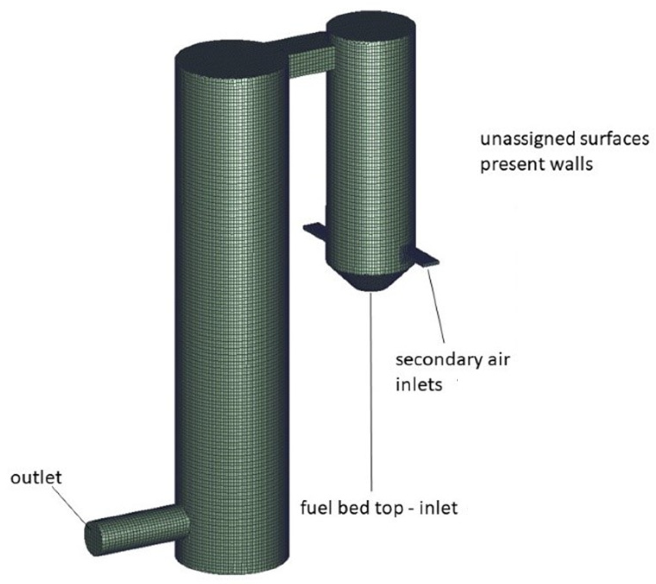
The preliminary small-scale system simulations were performed during system development in order to verify whether the proposed system design meets the gas residence time requirements and if it also imposes sufficient mixing in the freeboard. The simulations consider non-reactive flow with temperatures in the expected flue gas temperature ranges.
The preliminary simulations apply nearly the same numerical setup as the reactive flow simulations, performed with the surrogate-based combustion model and described in Section 2.4 of the manuscript. The differences are present only in the applied computational domain, boundary conditions that relate to the fuel bed and in the use of air as the sole fluid in the domain. These differences are described in the following paragraphs.
The computational domain in the preliminary simulations is shown in Figure A1. It includes the whole system geometry, that is, also the tertiary stage cyclone. The figure also points to the applied boundary conditions. These are at walls and the outlet equal to those in simulations with the surrogate-based combustion model, which are listed in Table 5. The fuel bed and secondary air inlets are defined with mass flows and temperatures of the air that enters the domain through them. The air entering through the fuel bed has a mass flow of 14.4 kg/h, while the two secondary air injections together provide 22.45 kg/h of air. Air enters the domain at 1150 K. The set temperature is in line with the temperature of flue gases, achieved during combustion, and reported in Table 8. The air mass flow is higher than the mass flow in experiments. Especially high is the air mass flow at the fuel bed. The reason for this lies in the need to obtain a robust design in terms of both mixing and flue gas residence time. Use of high mass flow from the fuel bed imposes conditions that are additionally challenging for ensuring these design requirements.
The applied mesh is also shown in Figure A1. The mesh features equal properties as the mesh for surrogate-based combustion model simulations. It features 226,500 elements in total.
Figure A1. The computational domain, applied in the preliminary simulations, with depicted computational mesh and boundary conditions.
Processes 13 03170 g0a1

Appendix A.2. Results of Preliminary Small-Scale System Simulations

The key to imposing suitable flow mixing and combustion of volatiles in the freeboard of the pilot small-scale system is in the efficient application of secondary air injections. The results of non-reactive flow simulations with different secondary air mass flows, shown in Figure A2, are used to depict this. The results show that the design of the secondary air injections maintains the same impact on the flow field for a wide range of secondary air mass flow magnitudes. The applied misalignment of the injections, together with their dimensions, imposes the cyclone flow, while the presence of the lower velocity region at the center is also ensured. The combination of the two allows for a stable flame presence at the secondary air injection location, which is then followed by efficient mixing of the primary and secondary flow in the freeboard.
Figure A2. Positioning of secondary air inlets with associated velocity field under non-reactive conditions and gradually increased secondary air mass flow.
Processes 13 03170 g0a2
A more detailed depiction of how the pilot small-scale system imposes suitable flow mixing and residence time is shown with results in Figure A3. Flow mixing is depicted by tracking the flow from secondary and primary air injections. For this, an additional passive scalar transport equation is solved. The secondary air flow is prescribed the passive scalar value of 1, and the primary air flow, the value 0. Residence time is calculated with the use of the Discrete Phase Model (DPM), where massless particles are injected into the domain from the fuel bed. Aside from being massless, the particles do not affect the flow, also due to the use of one-way coupling with the flow field, which imposes only the effects of the flow on the particles. The time of the particles in the domain is tracked, effectively defining the residence time of gases.
Figure A3. The results of non-reactive flow simulations which depict flow mixing (left) and residence time (right).
Processes 13 03170 g0a3
Results for the passive scalar field show that secondary air mixes with the primary and forms a homogeneous mixture within the distance of one diameter after the secondary air injection. The residence time results are depicted with the colors of the particles, limited a value of 2 s. They show that the flow is retained in the system for a considerably longer time, even in conditions of very high mass flows. It is thus concluded that the system design allows for thorough mixing of the flow, which is a prerequisite for efficient freeboard combustion. The imposed cyclone also allows for sufficiently uniform flow in the axial direction, resulting in the required residence time of combustion products. The analyses, performed with the preliminary non-reactive flow simulations, point to the implemented design features as the key to achieving well-controlled and suitable combustion of SS in such confined volume. The devised pilot small-scale system was thus considered suitable for use in the validation of the surrogate-based combustion model.

References

  1. Fonts, I.; Gea, G.; Azuara, M.; Ábrego, J.; Arauzo, J. Sewage sludge pyrolysis for liquid production: A review. Renew. Sustain. Energy Rev. 2012, 16, 2781–2805. [Google Scholar] [CrossRef]
  2. European Commission. Closing the Loop—An EU Action Plan for the Circular Economy; European Commission: Brussels, Belgium, 2015.
  3. European Commission. The European Green Deal; European Commission: Brussels, Belgium, 2019.
  4. Zhang, Y.; Wang, Y.; Chen, Z.; Hu, C.; Qu, J. Recovering nutrients and unblocking the cake layer of an electrochemical anaerobic membrane bioreactor. Nat. Commun. 2024, 15, 9111. [Google Scholar] [CrossRef] [PubMed]
  5. Krylova, A.Y.; Zaitchenko, V.M. Hydrothermal Carbonization of Biomass: A Review. Solid Fuel Chem. 2018, 52, 91–103. [Google Scholar] [CrossRef]
  6. Lima, D.; Li, L.; Appleby, G. A Review of Renewable Energy Technologies in Municipal Wastewater Treatment Plants (WWTPs). Energies 2024, 17, 6084. [Google Scholar] [CrossRef]
  7. Magdziarz, A.; Werle, S. Analysis of the combustion and pyrolysis of dried sewage sludge by TGA and MS. Waste Manag. 2014, 34, 174–179. [Google Scholar] [CrossRef]
  8. Fijalkowski, K.; Rorat, A.; Grobelak, A.; Kacprzak, M.J. The presence of contaminations in sewage sludge—The current situation. J. Environ. Manag. 2017, 203, 1126–1136. [Google Scholar] [CrossRef]
  9. Lin, H.; Ma, X. Simulation of co-incineration of sewage sludge with municipal solid waste in a grate furnace incinerator. Waste Manag. 2012, 32, 561–567. [Google Scholar] [CrossRef]
  10. Atienza-Martínez, M.; Gea, G.; Arauzo, J.; Kersten, S.R.A.; Kootstra, A.M.J. Phosphorus recovery from sewage sludge char ash. Biomass Bioenergy 2014, 65, 42–50. [Google Scholar] [CrossRef]
  11. Žnidarčič, A.; Seljak, T.; Katrašnik, T. Surrogate model for improved simulations of small-scale sludge incineration plants. Fuel 2020, 280, 118422. [Google Scholar] [CrossRef]
  12. Romano, P.; Zuffranieri, A.; Di Giacomo, G. Energy Valorization and Resource Recovery from Municipal Sewage Sludge: Evolution, Recent Advances, and Future Prospects. Energies 2025, 18, 3442. [Google Scholar] [CrossRef]
  13. GEMCO Energy. GEMCO Small Waste Incinerator. Available online: https://gasificationplant.com/pyrolysis-equipment/small-waste-incinerator/ (accessed on 4 July 2025).
  14. GEI Works. Small-Batch Incinerators. Available online: https://erosionpollution.com/wp-content/uploads/2023/08/GEI-Incinerator-Spec-Sheet.pdf (accessed on 4 July 2025).
  15. EMPYRIO. Sustainable Sewage Sludge Utilization in Small Cities. 2023. Available online: https://platform.cleantechscandinavia.com/wp-content/uploads/2023/12/EMPYRIO-pitch-deck-2023-12-07-2.pdf (accessed on 4 July 2025).
  16. Janković, B.; Manić, N.; Stojiljković, D. The gaseous products characterization of the pyrolysis process of various agricultural residues using TGA–DSC–MS techniques. J. Therm. Anal. Calorim. 2020, 139, 3091–3106. [Google Scholar] [CrossRef]
  17. Nowicki, L.; Ledakowicz, S. Comprehensive characterization of thermal decomposition of sewage sludge by TG-MS. J. Anal. Appl. Pyrolysis 2014, 110, 220–228. [Google Scholar] [CrossRef]
  18. Costa, M.; Massarotti, N.; Mauro, A.; Arpino, F.; Rocco, V. CFD modelling of a RDF incineration plant. Appl. Therm. Eng. 2016, 101, 710–719. [Google Scholar] [CrossRef]
  19. Murer, M.J.; Spliethoff, H.; de Waal, C.M.; Wilpshaar, S.; Berkhout, B.; Berlo, M.A.V.; Gohlke, O.; Martin, J.J. High efficient waste-to-energy in Amsterdam: Getting ready for the next steps. Waste Manag. Res. 2011, 29, S20–S29. [Google Scholar] [CrossRef]
  20. Frank, A.; Castaldi, M.J. CFD analysis of municipal solid waste combustion using detailed chemical kinetic modelling. Waste Manag. Res. 2014, 32, 745–754. [Google Scholar] [CrossRef]
  21. Mikulčić, H.; Von Berg, E.; Vujanović, M.; Duić, N. Numerical study of co-firing pulverized coal and biomass inside a cement calciner. Waste Manag. Res. 2014, 32, 661–669. [Google Scholar] [CrossRef] [PubMed]
  22. Yang, Y.B.; Yamauchi, H.; Nasserzadeh, V.; Swithenbank, J. Effects of fuel devolatilisation on the combustion of wood chips and incineration of simulated municipal solid wastes in a packed bed. Fuel 2003, 82, 2205–2221. [Google Scholar] [CrossRef]
  23. Costa, M.; Indrizzi, V.; Massarotti, N.; Mauro, A. Modeling and optimization of an incinerator plant for the reduction of the environmental impact. Int. J. Numer. Methods Heat Fluid Flow 2015, 25, 1463–1487. [Google Scholar] [CrossRef]
  24. Rajh, B.; Yin, C.; Samec, N.; Hriberšek, M.; Zadravec, M. Advanced modelling and testing of a 13 MWth waste wood-fired grate boiler with recycled flue gas. Energy Convers. Manag. 2016, 125, 230–241. [Google Scholar] [CrossRef]
  25. Rajh, B.; Yin, C.; Samec, N.; Hriberšek, M.; Kokalj, F.; Zadravec, M. Advanced CFD modelling of air and recycled flue gas staging in a waste wood-fired grate boiler for higher combustion efficiency and greater environmental benefits. J. Environ. Manag. 2018, 218, 200–208. [Google Scholar] [CrossRef]
  26. Mikulčić, H.; von Berg, E.; Vujanović, M.; Wang, X.; Tan, H.; Duić, N. Numerical evaluation of different pulverized coal and solid recovered fuel co-firing modes inside a large-scale cement calciner. Appl. Energy 2016, 184, 1292–1305. [Google Scholar] [CrossRef]
  27. Netzer, C.; Løvås, T. Chemical Model for Thermal Treatment of Sewage Sludge. ChemEngineering 2022, 6, 16. [Google Scholar] [CrossRef]
  28. Ortner, B.; Schmidberger, C.; Gerhardter, H.; Prieler, R.; Schröttner, H.; Hochenauer, C. Computationally Inexpensive CFD Approach for the Combustion of Sewage Sludge Powder, Including the Consideration of Water Content and Limestone Additive Variations. Energies 2023, 16, 1798. [Google Scholar] [CrossRef]
  29. Ortner, B.; Peham, L.; Schmidberger, C.; Prieler, R.; Hochenauer, C. CFD modeling of sewage sludge combustion in an experimental entrained flow reactor with integrated slag flow dynamics. Appl. Therm. Eng. 2025, 267, 125779. [Google Scholar] [CrossRef]
  30. Ortner, B.; Schmidberger, C.; Prieler, R.; Hochenauer, C. Computationally inexpensive CFD modeling of sewage sludge and waste additive combustion experiments in an entrained flow reactor. Fuel 2025, 389, 134797. [Google Scholar] [CrossRef]
  31. Žnidarčič, A.; Katrašnik, T.; Zsély, I.G.; Nagy, T.; Seljak, T. Sewage sludge combustion model with reduced chemical kinetics mechanisms. Energy Convers. Manag. 2021, 236, 114073. [Google Scholar] [CrossRef]
  32. Yao, H.; Naruse, I. Combustion characteristics of dried sewage sludge and control of trace-metal emission. Energy Fuels 2005, 19, 2298–2303. [Google Scholar] [CrossRef]
  33. Ninomiya, Y.; Zhang, L.; Sakano, T.; Kanaoka, C.; Masui, M. Transformation of mineral and emission of particulate matters during co-combustion of coal with sewage sludge. Fuel 2004, 83, 751–764. [Google Scholar] [CrossRef]
  34. Zhang, L.; Ito, M.; Sato, A.; Ninomiya, Y.; Sakano, T.; Kanaoka, C.; Masui, M. Combustibility of dried sewage sludge and its mineral transformation at different oxygen content in drop tube furnace. Fuel Process. Technol. 2004, 85, 983–1011. [Google Scholar] [CrossRef]
  35. Nyakuma, B.B.; Magdziarz, A.; Werle, S. Physicochemical, Thermal and Kinetic Analysis of Sewage Sludge. In Proceedings of the ECOpole’16 Conference, Zakopane, Poland, 5–8 October 2016; Volume 10. Available online: https://bibliotekanauki.pl/articles/126178 (accessed on 4 July 2025).
  36. Shao, J.; Yan, R.; Chen, H.; Wang, B.; Lee, D.H.; Liang, D.T. Pyrolysis Characteristics and Kinetics of Sewage Sludge by Thermogravimetry Fourier Transform Infrared Analysis. Energy Fuels 2008, 22, 38–45. [Google Scholar] [CrossRef]
  37. Conesa, J.A.; Marcilla, A.; Moral, R.; Moreno-Caselles, J.; Perez-Espinosa, A. Evolution of gases in the primary pyrolysis of different sewage sludges. Thermochim. Acta 1998, 313, 63–73. [Google Scholar] [CrossRef]
  38. Calvo, L.F.; Sánchez, M.E.; Morán, A.; García, A.I. TG-MS as a technique for a better monitoring of the pyrolysis, gasification and combustion of two kinds of sewage sludge. J. Therm. Anal. Calorim. 2004, 78, 587–598. [Google Scholar] [CrossRef]
  39. Thipkhunthod, P.; Meeyoo, V.; Rangsunvigit, P.; Kitiyanan, B.; Siemanond, K.; Rirksomboon, T. Pyrolytic characteristics of sewage sludge. Chemosphere 2006, 64, 955–962. [Google Scholar] [CrossRef] [PubMed]
  40. Urych, B.; Smoliński, A. Kinetics of Sewage Sludge Pyrolysis and Air Gasification of Its Chars. Energy Fuels 2016, 30, 4869–4878. [Google Scholar] [CrossRef]
  41. Gao, N.; Li, J.; Qi, B.; Li, A.; Duan, Y.; Wang, Z. Thermal analysis and products distribution of dried sewage sludge pyrolysis. J. Anal. Appl. Pyrolysis 2014, 105, 43–48. [Google Scholar] [CrossRef]
  42. Huang, Q.; Yu, B.; Qiu, K.; Zhou, G.; Wang, S.; Chi, Y.; Yan, J. Effect of moisture on sewage sludge combustion temperature profile and heavy metal leaching. Dry. Technol. 2016, 34, 1810–1819. [Google Scholar] [CrossRef]
  43. Deng, S.; Wang, X.; Tan, H.; Mikulčić, H.; Li, Z.; Cao, R.; Wang, Z.; Vujanović, M. Experimental and modeling study of the long cylindrical oily sludge drying process. Appl. Therm. Eng. 2015, 91, 354–362. [Google Scholar] [CrossRef]
  44. Rosec, Ž.; Katrašnik, T.; Žvar Baškovič, U.; Seljak, T. Exhaust gas recirculation with highly oxygenated fuels in gas turbines. Fuel 2020, 278, 118285. [Google Scholar] [CrossRef]
  45. Agwu, O.; Valera-Medina, A.; Katrašnik, T.; Seljak, T. Flame characteristics of glycerol/methanol blends in a swirl-stabilised gas turbine burner. Fuel 2021, 290, 119968. [Google Scholar] [CrossRef]
  46. Ischia, M.; Perazzolli, C.; Dal Maschio, R.; Campostrini, R. Pyrolysis study of sewage sludge by TG-MS and TG-GC-MS coupled analyses. J. Therm. Anal. Calorim. 2007, 87, 567–574. [Google Scholar] [CrossRef]
  47. Yang, Y.B.; Goh, Y.R.; Zakaria, R.; Nasserzadeh, V.; Swithenbank, J. Mathematical modelling of MSW incineration on a travelling bed. Waste Manag. 2002, 22, 369–380. [Google Scholar] [CrossRef]
  48. Nagy, T.; Turányi, T. Reduction of very large reaction mechanisms using methods based on simulation error minimization. Combust. Flame 2009, 156, 417–428. [Google Scholar] [CrossRef]
  49. Zsély, I.G.; Nagy, T.; Simmie, J.M.; Curran, H.J. Reduction of a detailed kinetic model for the ignition of methane/propane mixtures at gas turbine conditions using simulation error minimization methods. Combust. Flame 2011, 158, 1469–1479. [Google Scholar] [CrossRef]
  50. Zsély, I.G.; Nagy, T.; Simmie, J.M.; Curran, H.J. Reduction of a detailed kinetic model for the ignition of natural gas mixtures at gas turbine conditions. In Proceedings of the 4th European Combustion Meeting (ECM 2009), Vienna, Austria, 11–17 April 2009. [Google Scholar]
  51. Olm, C.; Varga, T.; Valkó, É.; Hartl, S.; Hasse, C.; Turányi, T. Development of an Ethanol Combustion Mechanism Based on a Hierarchical Optimization Approach. Int. J. Chem. Kinet. 2016, 48, 423–441. [Google Scholar] [CrossRef]
  52. European Council. Directive 2010/75/EU of the European Parliament and of the Council of 24 November 2010 on industrial emissions (integrated pollution prevention and control). Off. J. Eur. Union 2010, 53, 17–119. [Google Scholar] [CrossRef]
  53. AVL. AVL FIRETM-avl.com. 2021. Available online: https://www.avl.com/en/simulation-solutions/software-offering/simulation-tools-a-z/avl-fire-m (accessed on 3 June 2025).
  54. Seljak, T.; Katrašnik, T.; Žnidarčič, A. Sludge to energy in sub-Megawatt incineration plants. In Proceedings of the International Conference on Technologies and Business Models for Circular Economy (TBMCE 2018), Portorož, Slovenia, 5–7 September 2018. [Google Scholar]
  55. Popovac, M.; Hanjalic, K. Compound Wall Treatment for RANS Computation of Complex Turbulent Flows and Heat Transfer. Flow. Turbul. Combust. 2007, 78, 177. [Google Scholar] [CrossRef]
  56. Kong, S.-C.; Reitz, R.D. Use of Detailed Chemical Kinetics to Study HCCI Engine Combustion With Consideration of Turbulent Mixing Effects. J. Eng. Gas Turbines Power 2002, 124, 702–707. [Google Scholar] [CrossRef]
Figure 1. The development process of the advanced SS surrogate-based combustion model for small-scale sludge incineration system simulations.
Processes 13 03170 g001
Figure 2. Framework of the surrogate-based combustion model.
Processes 13 03170 g002
Figure 3. CAD of the gas phase domain with main dimensions (left); constructed system at the operating site with depicted main parts (right).
Processes 13 03170 g003
Figure 4. Simplified scheme of constructed system with key supporting systems and indicated positions of monitoring equipment.
Processes 13 03170 g004
Figure 5. Computational domain shown with the mesh and its depicted boundaries.
Processes 13 03170 g005
Figure 6. Secondary combustion zone as seen through the view port positioned centrally above.
Processes 13 03170 g006
Figure 7. Temperature contours at mid-section for coarse (left, 63,000 elements), medium (middle, 164,500 elements), and fine (right, 500,000 elements) meshes.
Processes 13 03170 g007
Figure 8. Temperature profiles obtained for the three applied meshes at 12 cm from the secondary air inlets.
Processes 13 03170 g008
Figure 9. CO mass fraction (left), temperature field (middle), and OH radical iso-surface ((right), OH mass fraction of 5 × 10⁻⁵) in simulations of experimentally observed combustion.
Processes 13 03170 g009
Figure 10. O radical (left), CH3 radical (middle), and C2H2 (right) mass fractions at mid-cross section.
Processes 13 03170 g010
Figure 11. Cross sections of temperature fields at λ values from 1.5 (left) to 2 (right).
Processes 13 03170 g011
Figure 12. I so-surfaces of the OH radical (OH mass fraction of 5 × 10⁻⁵) at λ values from 1.5 (left) to 2 (right).
Processes 13 03170 g012
Figure 13. Cross section of the O radical mass fractions at λ values from 1.5 (left) to 2 (right).
Processes 13 03170 g013
Figure 14. Cross section of the C2H2 mass fractions at λ values from 1.5 (left) to 2 (right).
Processes 13 03170 g014
Figure 15. Cross sections of temperature fields in the case of increased moisture presence at λ values from 1.7 (left) to 2 (right).
Processes 13 03170 g015
Figure 16. Iso-surfaces of the OH radical (OH mass fraction of 5 × 10⁻⁵) in the case of increased moisture presence at λ values from 1.7 (left) to 2 (right).
Processes 13 03170 g016
Figure 17. Cross sections of temperature fields in the case of variable bed temperatures.
Processes 13 03170 g017
Figure 18. Iso-surfaces of OH radical (OH mass fraction of 5 × 10⁻⁵) for variable bed temperatures.
Processes 13 03170 g018
Figure 19. Cross sections of temperature fields in the case of various imposed thermal powers.
Processes 13 03170 g019
Figure 20. Iso-surfaces of the OH radical (OH mass fraction of 5 × 10⁻⁵) in the case of various imposed thermal powers.
Processes 13 03170 g020
Table 1. Existing small-scale incineration systems for SS.
SystemConstructionCapacityFlue Gas CleaningSource
Small-scale waste incinerator,
GEMCO (Shanghai, China)
Pyrolysis and combustion in a dual-chamber system30 to 50 kg/hQuenching and acid removal, cyclone and bag filters[13]
HELIOS 0.3,
GEI Works (Palm Bay, FL, USA)
Gasification and combustion in a dual-chamber system13 to 23 kg/h of waste with up to 9 MJ/kg higher heating value (HHV)Not disclosed[14]
Empyrio system,
Empyrio (Riga, Latvia)
Incinerator and after-burner500 t/y of dry matterNot disclosed[15]
Table 2. SS properties as defined in the listed literature sources.
VariableMass Fraction [%]Sources
AshMostly 20–30, can reach 50[32,33,34,35,36,37,38,39]
MoistureMostly 4–20, can reach 80[7,32,35,36,40,41,42]
VolatilesApprox. 50, can reach 70[7,32,33,35,36,38,40,41]
CarbonMainly around 30[7,35,36,39,40,41]
OxygenMainly around 20[7,35,36,39,40,41]
Table 3. The chosen surrogate composition, taken from [11] and used to form surrogates for combustion simulations in the small-scale system.
SpeciesCOH2OH2CH4C2H5OHCO2
Mass fr. [%]69.279.830.3410.2910.270
Chemical energy fraction [%]43.0802.9735.1818.770
Table 4. The size of the reference and the reduced mechanisms for ethanol.
MechanismNumber of
Species
Number of Reversible ReactionsNumber of Irreversible Reactions
Reference472492
Reduced331682
Table 5. Description of applied boundary conditions.
Fuel bed inletDispersed and separated positions of surrogates and remaining air inflows, with defined composition, mass flow, and temperature. Surface emissivity factor set as 1.
Secondary air inletsAir mass flow and temperature definition.
WallsNo-slip boundary condition.
Surface emissivity factor of 0.8 (estimated for rust iron with a film of carbon deposits).
Thermal resistance value set at 1.25 m2K/W.
Convective heat transfer to the environment with 25 W/m2K.
Environment temperature set at 293 K.
OutletStatic (atmospheric) pressure of 1 bar.
Table 6. Flow models and discretization schemes.
Governing equations and their solution algorithmUnsteady compressible Navier–Stokes momentum, continuity, and energy equations, including the terms for gravity and pressure work.
Coupled Navier–Stokes equations are solved via the SIMPLE algorithm.
Applied modelsTurbulence k-ζ-f model.
Hybrid wall functions for velocity profile solution at the wall.
Standard wall function for wall heat transfer description.
Ideal gas law for gas density.
Discrete transfer radiation model with gas as a participating medium (Weighted-Sum-of-Gray-Gases model).
Discretization schemesSecond-order temporal discretization (Δt = 0.01 s).
Blended upwind and central difference schemes for mom. Equations.
Central difference scheme for the continuity equation.
Upwind scheme for energy, turbulence, and scalar transport equations.
Least squares fit method for the definition of derivatives.
Table 7. The applied operating conditions in continuous system operation.
ParameterSetting
Sludge mass flow2.93 kg/h
Primary air mass flow3.045 kg/h
Secondary air mass flow19.79 kg/h
Primary air temperature413 K
Secondary air temperature273 K
Ambient temperature273 K
Table 8. Measured temperatures during continuous system operation.
Measuring PositionAverage Temperature and
Standard Deviation [K]
Combined Measurement
Uncertainty [K]
Fuel bed, T31423 ± 4545.1
13 cm after secondary
air injection, T1
1273 + 13.413.8
46 cm after secondary air
injection (near cyclone top), T2
1213 + 6.57.2
Table 9. The applied inlet boundary conditions in the mesh independence study.
InletComposition
(% Mass Fraction)
Mass Flow [kg/h]Temperature [K]
Fuel bed, combustible speciesMethane (100%)0.648918
Fuel bed, inert speciesMethane combustion products (15% CO2, 12% H2O, 73% N2)3.042 918
Secondary air inletsAir (23% O2, 77% N2)21.6273
Table 10. The tailored surrogate composition applied in combustion simulations.
SpeciesCOH2OH2CH4C2H5OHCO2
Mass fr. [%]59.0518.50.368.478.355.27
Chemical en. fraction [%]43.703.6934.4518.160
Table 11. Comparison of measured and simulated temperatures at two measuring positions in the secondary stage cyclone.
PositionMeasured
Temperature [K]
Simulated
Temperature [K]
Difference
[K]
T11273129421
T21213124330
Disclaimer/Publisher’s Note: The statements, opinions and data contained in all publications are solely those of the individual author(s) and contributor(s) and not of MDPI and/or the editor(s). MDPI and/or the editor(s) disclaim responsibility for any injury to people or property resulting from any ideas, methods, instructions or products referred to in the content.