Abstract
The aim of the present study is to investigate the mechanism behind corrosion destruction in laser-melted layers (LMLs) of AISI 321 austenitic stainless steel after electrochemical corrosion in Ringer’s solution. Surface morphology, microstructure, chemical composition, grain sizes, and orientation are studied using OM, SEM, EDS, and EBSD. It was confirmed that (1) the main mechanism behind corrosion destruction is identical between untreated and laser-melted steel, i.e., the selective destruction of the lower corrosion resistance phase (δ-ferrite) in the form of pits, and (2) the morphology and size of corrosion pits are different, as determined via δ-ferrite morphology, with narrow deep pits of uneven shape observed on the surface of wrought steel and rounded shallower pits seen in LML. The following mechanism is proposed with regard to corrosion destruction in LML: (1) the initial destruction of δ-ferrite; (2) the formation of an austenitic dendrite network; (3) the mechanical fracture of austenitic dendrites and pit formation; and (4) the growth of pits inside the grain. The following relationship between corrosion pit development and dendrite orientation in the LML is observed: (1) In the melted zone, with dendrite axes perpendicular to or inclined toward the surface, the corrosion pit grows within the grain. (2) At the melted zone/base metal (MZ/BM) boundary, with dendrite axes parallel to the surface, the corrosion pit develops in the heat-affected zone, along the MZ/BM boundary.
1. Introduction
Biomedical metals and alloys are widely used in the manufacturing of implants, devices, and surgical instruments in general and dental medicine. According to their definition, implants are artificial structures whose purpose is to replace or stabilize a damaged function or part of the body. They have found widespread application in orthopedic reconstructions (hip, knee, shoulder, and elbow implants), fracture fixation (plates, pins, screws, rods, and nails), oral and maxillofacial reconstructions (dental implants and mini-plates), and cardiovascular interventions (stents, heart valves, and pacemakers) [1,2,3,4]. As biomedical constructions, implants have to meet high requirements, as follows: (1) implants must be biocompatible, to remain in the body for a long time and interact normally with living tissues; (2) they must effectively perform their physical functions without harming or irritating the patient; and (3) the implant materials must possess the mechanical properties necessary for their respective applications.
The main metallic materials used in implant production include pure titanium and its alloys, Co-Cr alloys, and stainless steel [1,2]. Austenitic stainless steels possess high corrosion resistance and biocompatibility and good mechanical and technological properties and have further advantages of reasonable cost and availability [2]. Among them, the AISI 316 and 316L types have found widespread application in coronary stents, orthopedic implants, and devices for fracture fixation, while the AISI 304 and 304L types are mainly used for orthodontic wires in dentistry [3,4].
In recent decades, equipment based on laser technologies has been widely implemented in the fabrication of biomedical constructions. Stents and complex dental constructions can be produced via laser cutting and laser welding [5,6,7,8]. The surface properties of the metal details can be modified and improved via laser cladding or laser heat treatment [9,10,11]. The application of new additive manufacturing technology (AMT) has allowed the fast fabrication of personalized implants with low material wastage. Most types of AMT, working with metallic powders, use a laser as a heating source: laser rapid manufacturing (LRM), selective laser melting (SLM), direct laser deposition (DLD), direct metal laser sintering (DMLS), etc. [2,3,4,12,13,14,15]. During laser processing technologies, the heating and melting of the metal surface or metal powder are performed at high speed, followed by fast cooling. This yields a metastable fine-grained and more homogeneous microstructure in the surface layer, leading a change in the mechanical properties and corrosion resistance of the fabricated object.
Implants in the human body must be able to function under the highly corrosive environmental conditions caused by body fluids. These contain chloride, hydroxide and other ions, bacteria, proteins, and dissolved oxygen. The pH of the body is usually around 7.4, although, after operations or due to hematomas, inflammations, and infections, it can vary between 4.0 and 9.0 [16]. Therefore, it is very important that we investigate the level of corrosion resistance achieved using different technologies, as this property determines the biocompatibility of implant materials and implants themselves.
It has been found that laser surface treatments, such as laser melting, laser texturing, and laser cladding, can improve the corrosion resistance of austenitic stainless steels. The laser melting of the surface of AISI 316 steel leads to a homogeneously modified surface layer that possesses a fine dendritic microstructure and higher corrosion resistance [11]. Improved corrosion resistance is achieved via the laser texturing of the surface of AISI 304 steel [17]. The corrosion resistance of AISI 304L steel after laser cladding is higher compared to the untreated steel, and corrosion pits are propagated in a horizontal direction [18]. The laser-melted layers of AISI 321 steel are characterized by a fine-grained microstructure and lower hardness [19]. This leads to an improved passive layer on the laser-melted surface of AISI 321 steel and increased resistance to pitting corrosion in Ringer’s solution and artificial saliva (AS) with pH 6.5 [20,21]. However, during the electrochemical corrosion test in AS with pH 5.6, the corrosion resistance of the laser-melted layers is lower than that of the wrought steel.
In recent years, significant attention has been given to the corrosion processes occurring on the surfaces of AMT-fabricated austenitic stainless steels in biological fluids. According to Laleh M. et al. [22], an SLM-produced 316L specimen showed lower intergranular corrosion along its grain boundaries compared to the wrought one. In their investigation into AISI 316L steel produced via SLM and laser metal deposition (LMD), Revilla R. I. et al. [14] found a much finer microstructure in the SLM sample compared to the LMD one. This could promote the formation of a more compact and stabile oxide layer, leading to higher corrosion resistance. Kong D. et al. [2] studied the influence of the laser power on the microstructure, mechanical properties, and corrosion in simulated body fluids (SBFs) of SLM-produced AISI 316L steel. They revealed that the steel fabricated at high laser power showed higher elongation, corrosion resistance, and biocompatibility. The higher densities of the grain boundaries, sub-grain boundaries, and dislocations in SLM-fabricated AISI 316 steel lead to a thicker passive layer, meaning higher corrosion resistance, in SBF compared to wrought steel [3]. According to Tarasov S.Y. et al. [23], the corrosion resistance of AISI 304 steel produced via AMT depends on the δ-ferrite content in the microstructure: the higher the δ-ferrite content, the lower the corrosion resistance. It should be kept in mind that post-heat treatment decreases the corrosion resistance of SLM-fabricated AISI 316L steel in 3.5 wt.% NaCl solution and in borate buffer solution (pH 9.0) [24,25].
Many researchers have investigated the corrosion properties of austenitic stainless steels produced using laser-based technologies. These properties have varied according to the parameters of laser treatment (laser power, scanning speed, laser spot diameter), the scanning strategy, post-heat treatment, and the corrosive environment. Most studies have revealed that as-received SLM-fabricated stainless steels are characterized by higher corrosion resistance compared to wrought steel due to the more homogeneous fine-grained microstructure and thicker oxide layer on the surface [24,25,26,27,28,29]. However, it is mostly AISI 316L steel that is investigated. Information on the microstructure and corrosion properties of other types of austenitic stainless steel produced or treated using laser technologies is relatively scarce [17,19,21,23].
In this study, we aim to investigate the morphology and microstructure of the surface layer of AISI 321 austenitic stainless steel after laser melting and electrochemical corrosion in Ringer’s solution and, on this basis, to reveal the mechanism behind corrosion destruction and the development of pits at depths in the laser-melted layers. The surface morphology and microstructure are observed using optical and scanning electron microscopy (SEM), the chemical composition is defined via energy-dispersive spectroscopy (EDS), and the grain sizes and orientation are evaluated via electron back-scattered diffraction (EBSD) analyses. This study is a continuation of our research on the electrochemical corrosion of laser-melted layers of AISI 321 steel in biological fluids [20,21,30].
2. Materials and Methods
2.1. Materials and Sample Preparation
Milled prismatic samples (10 mm × 30 mm × 100 mm) were used in the experiment. These were made of austenitic stainless steel AISI 321 (EN X6CrNiTi 18-10), with the following chemical composition in wt.%: 0.075% C; 18.20% Cr; 10.85% Ni; 0.98 Si; 1.82% Mn; 0.042% P; 0.012% S; 0.52% Ti; and the rest Fe. After milling, the sample surface was ground and treated with a laser. A continuous-wave (CW) CO2 laser was used for the surface treatment with an initial power N = 1.2 kW and wavelength λ = 10.6 μm. A single pass was performed in the middle of the sample’s 30 mm side. Laser treatment was performed following the regimes shown in Table 1. They ensured that the surface layer was melted to different depths by varying the laser spot diameter d [cm] and scanning speed V [cm/s]. The technological parameters of power density Ns [W/cm2] and volume energy density Ev [J/cm3] were calculated using the formulas given in previous works [20,21]. The laser-melted surfaces were ground and polished to different roughness grades.

Table 1.
Surface treatment of the samples.
2.2. Electrochemical Corrosion Test
Prismatic samples (10 mm × 30 mm × 10 mm) were cut for the electrochemical corrosion test. Three specimens of each group were used in the experiment. Before the test, all samples were polished for 15 min, washed, and degreased. The electrochemical corrosion tests were carried out at a temperature of 37° in Ringer’s solution with the following composition: 9 g/L NaCl, 0.42 g/L KCl, 0.48 g/L CaCl2, and 0.2 g/L NaHCO3. Two tests were performed: the measurement of the open-circuit potentials (free potentials) Ef until reaching the steady-state potentials Ess and potentiodynamic anodic polarization. The external anodic polarization was carried out using a RADELKIS OH-405 potentiostat (Radelkis, Budapest, Hungary) with a standard three-electrode cell connected to it. The specimen investigated was used as the working electrode, a saturated calomel electrode was the reference electrode, and a platinum electrode was the counter electrode. The polarization potential was changed from −550 mV to +1250 mV at a rate of 1 mV/s. More detailed information, including polarization curves, can be found in the works of Dikova et al. [20,30].
2.3. Sample Characterization
The surface morphology of all specimens before and after the electrochemical corrosion test was observed using the optical microscopes (OMs) Olympus SZ51 (Leica Microsystems, Wetzlar, Germany) and XJL-17A (Hinotek, Ningbo, China). The samples’ surface and chemical composition were examined using a scanning electron microscope (SEM/FIB LYRA I XMU, TESCAN, Brno, Czech Republic) equipped with an EDX detector (Quantax 200, Bruker, Berlin, Germany).
To study the microstructure before and after the electrochemical corrosion test, the samples were cut along the diagonal of the area subjected to corrosion tests or in maximum proximity to corrosion defects. The as-obtained cross-sections were ground successively with sandpaper P400, P800, P1200, and P1500. Then, they were polished sequentially with UltraPad and MetaDi Supreme 9 μm diamond suspension, then with TriDent and MetaDi Supreme 3 μm diamond suspension, and finally with ChemoMet and MasterPrep Aluminum final polishing suspension. The polished surface was etched with HCl:HNO3 solution with a 3:1 ratio. The EBSD investigation was performed using the polished specimen, while the microstructure was observed on the etched specimens.
The investigation of the microstructure and in-depth corrosion destruction was carried out on preliminary prepared cross-sections using different microscopes, as follows:
- For OM, the Leica M 80 (Leica Microsystems, Manheim, Germany) with the Leica IC 90 E digital camera was used.
- For SEM, the Zeiss Evo 10 SEM (Jena, Germany) was used. The micrographs were taken in variable pressure mode using secondary electron detection. The chemical composition on the surface of the samples was registered with a Zeiss SmartEDX energy-dispersive X-ray probe.
- For SEM, the Gemini SEM 460 (Carl Zeiss Microscopy, Cambourne, UK), equipped with the Ultim Max EDS detector and CMOS EBSD detector, was used. The EDS and EBSD data were analyzed using AZtecCrystal 3.3 software from Oxford Instruments (Oxford Instruments Nanotechnology Limited, Oxford, UK).
3. Results
3.1. Microstructure and Chemical Composition
The microstructure of the investigated as-received AISI 321 steel before and after laser surface melting is shown in Figure 1. Nearly equiaxed austenitic grains with twinning, strip-like δ-ferrite and small carbides along the austenitic grain boundaries are observed in the base metal (Figure 1a–d). The melted surface layer consists of a melted zone (MZ) and heat-affected zone (HAZ), which are characterized by an inhomogeneous dendritic morphology (Figure 1c,d). Depending on the cooling rate, the MZ consists of small equiaxed grains on the top surface (Figure 1c) and larger dendrites, elongated along the direction of the temperature gradient, at the boundary between MZ and HAZ (Figure 1d,e). Our previous investigations have found structural heredity in HAZ, with dendrites growing within the original austenite grain [31]. Stavrev D. et al. [19] stated that the δ-ferrite phase occurs in a larger quantity at the melted pool bottom.
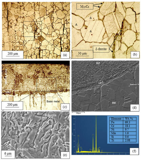
Figure 1.
Microstructure of: (a,b) AISI 321 austenitic steel; (c,d,f) Laser melted layer; (f) Chemical composition of the investigated steel. (a–c) OM images; (d,e) SEM image. (MZ—melted zone, HAZ—heat affected zone, BM—base metal, A—austenite).
Our investigation into the chemical composition showed that the base metal consists of Fe 69.3%, Cr 18.1%, Ni 9.7%, Mn 1.6%, Si 0.6%, and Ti 0.6% (wt.%) (Figure 1f). However, the chemical elements are unevenly distributed in the untreated steel (Figure 2 and Figure 3). An increase in Cr content (20.5–22.9%) and decrease in Ni (7.2–5.3%) content is noted in the δ-ferrite grains (Figure 2a). Titanium carbide strips are also observed in the microstructure of the as-received AISI 321 steel (Figure 3f). The MZ is characterized by a more homogeneous distribution of the chemical elements (Figure 2a and Figure 3).
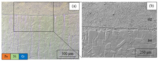
Figure 2.
(a) Distribution of Fe, Ni and Cr in the base metal and laser melted layer; (b) SEM image of melted zone and base metal of AISI 321 steel.
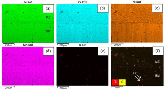
Figure 3.
Map of chemical elements in the microstructure of AISI 321 steel, shown in Figure 2b. (a) Fe; (b) Cr; (c) Ni; (d) Mn; (e) Ti; (f) Ti and C.
The EBSD study confirmed that the microstructure of the steel consists of two main phases: austenite and δ-ferrite (Figure 4). In the untreated steel, the δ-ferrite is situated in strip-like grains (Figure 4b), while in the MZ, the δ-ferrite is distributed more homogeneously in the interdendritic spaces (Figure 1e and Figure 4b).
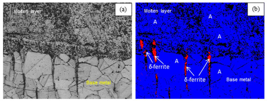
Figure 4.
EBSD study of (a) Microstructure and (b) Phase composition of AISI 321 steel (blue—iron fcc, A—austenite; red—iron bcc, δ-ferrite, crystal lattices).
The crystallographic orientation and sizes of the grains are shown in Table 2 and Figure 5. The grains of the as-received steel are characterized by a regular polygonal shape and straight boundaries. Their perimeter varies in the range of 11–882 µm. The melted zone consists of irregular grains elongated along the temperature gradient direction. Due to their wave-like boundaries, the perimeter of the grains in the BM/MZ transition zone varies in the larger range of 23–1165 µm. The mean value of the grain perimeter in the BM/MZ transition zone (209 µm) is slightly higher than that in the BM (190 µm). Similar results were obtained in investigation of AISI 316L steel by other researchers [2,3,24,25]. In addition, we found many sub-grains with a high dislocation concentration at the sub-grain boundaries in the SLM-produced steel.
Table 2.
Grain sizes results.
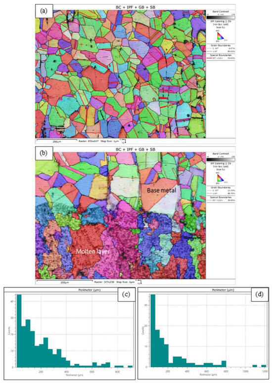
Figure 5.
Crystallographic orientation of: (a) Base metal (the white arrow shows sub-grain boundary), (b) BM/MZ transition layer. Grain sizes of: (c) Base metal, (d) BM/MZ transition layer of AISI 321 steel.
Consequently, the laser melting of AISI 321 austenitic stainless steel leads to the formation of a surface layer with a dendritic microstructure and a more homogeneous chemical and phase composition.
3.2. Corrosion Destruction
The steel surface after the electrochemical corrosion test in Ringer’s solution is shown in Figure 6. We found in our previous investigation that a large number of small pits with an irregular shape and nearly smooth walls can be observed on the surface of untreated AISI 321 steel [30]. Their sizes vary between 10 µm for a single pit up to over 300 µm for coagulated ones. The sizes of pits on the laser0melted surfaces are in the similar range of 10–400 µm. However, they have a rounded shape, rough walls, lower depth, and a cellular-like morphology at the bottom. Our results agree with the findings of Kong D. et al. [2] and Li B. et al. [26]. Further microscope studies have shown that in untreated steel, corrosion pits develop at a significant depth (50–300 µm) in areas and directions that completely coincide with those of the δ-ferrite grains (Figure 7). In addition, intergranular corrosion takes place along the boundaries of the austenitic grains near the surface [30].
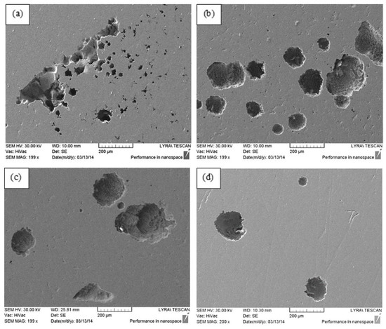
Figure 6.
Destruction of the steel surface after electro-chemical corrosion test in Ringer solution. (a) Untreated surface of sample 0. Laser melted surfaces of: (b) Sample 1; (c) Sample 4; (d) Sample 6 (SEM images).
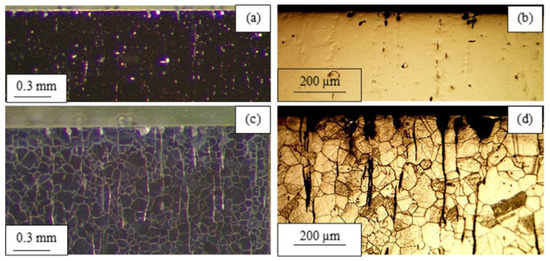
Figure 7.
Corrosion destruction in depth of AISI 321 steel (OM images of sample 0): (a,b) After polishing; (c,d) After etching.
Studying the chemical composition in different zones along the pit’s depth (Figure 8a) shows an oxygen increase and an iron decrease (Figure 8b–e). Therefore, the formations on the walls and inside the pits are of an oxide nature. At the pit’s bottom, a well-shaped metal oxide with 13.16% oxygen is observed (Figure 8f,g). This provides evidence for the way in which corrosion destruction occurs in the steel depth.
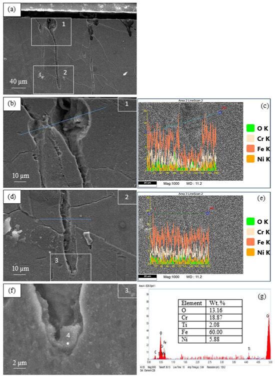
Figure 8.
Chemical composition in different zones along the pit’s depth of AISI 321 steel (sample 0). (a) Corrosion pits; (b) corrosion pit on the surface; (c) distribution of chemical elements along the line, shown in Figure 8b; (d) bottom part of corrosion pit; (e) distribution of chemical elements along the line, shown in Figure 8d; (f) higher magnification of the corrosion pit’s bottom; (g) chemical composition in the bottom of corrosion pit.
Similar results are shown in Figure 9. However, at the bottom of the pit, the oxygen content is low (1.74%), and the amount of other elements is close to the basic composition of the steel. Analysis of the distribution of chemical elements in the area around the corrosion crack (Figure 10) shows a uniform distribution of Fe, Cr, and Ni in the microstructure of the metal and the absence of oxygen in the pitting crack. Therefore, the formation at the pit’s bottom is a segment of the δ-ferrite grain that has not yet been oxidized. This is direct evidence of corrosion destruction, primarily of the ferrite grains, in the untreated austenitic AISI 321 steel.
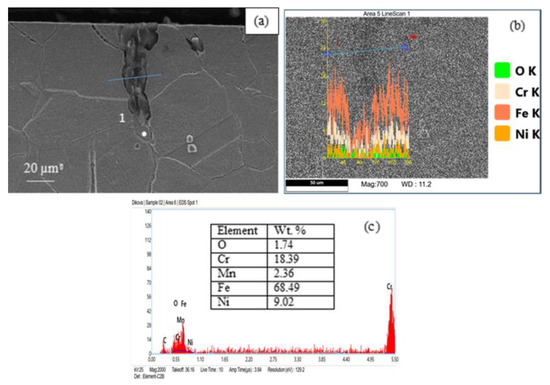
Figure 9.
(a) Corrosion pit on the surface of wrought AISI 321 steel (sample 0); (b) Chemical composition along the line of corrosion pit; (c) Content of the chemical elements in the pit’s bottom.
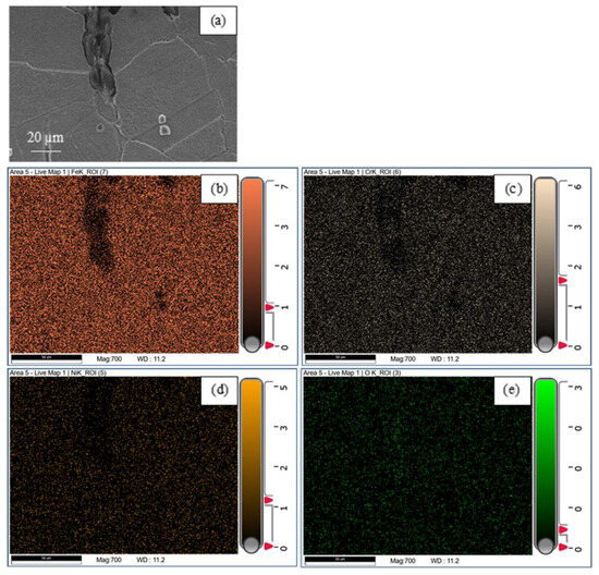
Figure 10.
Map of chemical elements in the zone of corrosion crack. (a) Corrosion crack; (b) Fe; (c) Cr; (d) Ni, (e) O.
Figure 11 shows corrosion pits on the surface of the laser-melted layers of AISI 321 steel. Our previous investigation showed that these are characterized by a shallower depth (40–100 µm) and rounded shape [30].
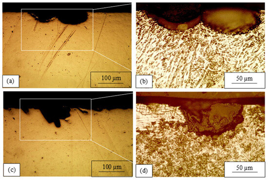
Figure 11.
Development of corrosion destruction in depth of laser melted layer of AISI 321 steel: (a,b) Sample 4; (c,d) Sample 6; (OM images).
In the SEM images of the laser-melted layers in Figure 12, many dendrites residues can be observed along the pits’ walls. Analysis of the chemical composition at different points in a pit at the BM/MZ boundary shows a difference in the element content (Figure 12a,c). The chemical composition at point 1, located in an austenitic grain of the BM (Figure 12a), is very similar to that at point 4 of the dendrite in the laser-melted layer (Figure 12b). This confirms our assumptions that the remnants of dendrites on the walls of the corrosion pits have an austenitic structure. The chemical composition at point 3 of the laser-melted layer in Figure 12a shows an increased amount of oxygen (7.47%), most likely due to the proximity of this point to the sample’s surface. The highest oxygen content is found at point 2 (12.75%), which is located at the bottom of the pit in the BM. In addition, there is a lack of chromium there. The observed formation is most likely a metal oxide containing mainly iron (78.51% Fe).
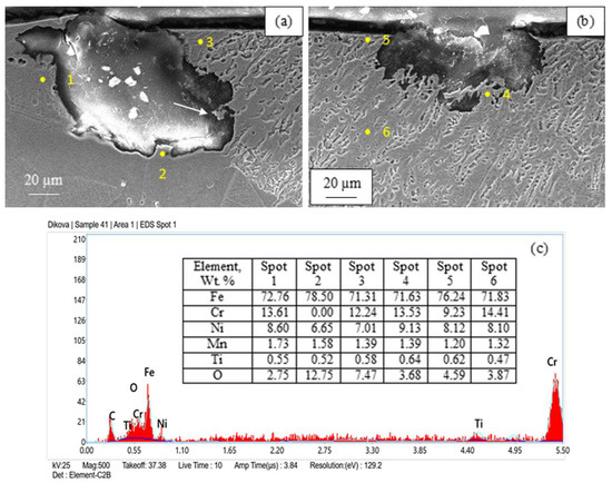
Figure 12.
(a,b) Corrosion destruction in depth of laser melted layer of AISI 321 steel (sample 4); (c) Chemical composition in different spots. (The white arrow in Figure 8a shows nearly broken dendrite).
There is no significant difference in the chemical composition at different points in the laser-melted layer (Figure 12b,c). Iron comprises 71.63–76.24%, Mn comprises 1.20–1.39%, and oxygen makes up 3.68–4.59%. However, the amounts of Cr and Ni are lower: 9.23–14.41% and 8.10–9.13%, respectively. It should be kept in mind that all measurements were carried out in the areas within the dendrites. It is very difficult to measure the chemical composition of interdendritic spaces due to the limitations of the equipment. Therefore, it was confirmed that the dendrites in the laser-melted layer of AISI 321 steel are homogeneous in chemical composition.
4. Discussion
In in vivo applications of biomedical alloys, the implant construction, corrosive media, and operating conditions affect the mechanism behind corrosion destruction. Eight main corrosion mechanisms are known to occur under in vivo conditions: crevice corrosion, pitting, intergranular, selective and galvanic corrosion, stress corrosion cracking, corrosion fatigue, and tribocorrosion [16]. In austenitic stainless steels, crevice and pitting corrosion are the most common destruction mechanisms [4,20,26]. However, there is a difference in the pit initiation sites on the surfaces of the wrought and laser-treated steel. In the as-received steel, the pit formation begins mostly at the inclusions: MnS, Al2O3, or mixed [2,3,25,26,27]. The metal surfaces treated via laser surface melting or produced via SLM are characterized by a microstructure that is more homogeneous, fine-grained, and nearly free of inclusions [14,19,26,31]. Even when inclusions occur, their size is much smaller (50–200 nm) compared to those in the wrought steel [3]. In these cases, defects in manufacturing, such as gas pores or lack-of-fusion (LOF) pores, represent the preferential sites for pit initiation [2,3,25,26,27,28]. A number of factors influence the corrosion behavior of stainless steel: the surface roughness and passive layer, grain sizes and porosity, chemical element distribution, embedded particles, etc. [4].
After electrochemical corrosion tests in physiological Ringer’s solution, selective pitting corrosion, mainly through the destruction of δ-ferrite grains, was observed in the surface layer of the as-received AISI 321 steel (Figure 6a and Figure 7). Near the surface, along the austenitic grain boundaries, intergranular corrosion was present [30]. These corrosion mechanisms are determined based on (1) the main two-phase structure of the wrought steel and the presence of carbides along the grain boundaries; (2) the stripe-like shape of the δ-ferrite and its lower corrosion resistance.
The inhomogeneous Cr content in the untreated steel (higher in the δ-ferrite and lower at the boundary with the austenite grains) could lead to the formation of a passive oxide layer with uneven thickness on the steel surface. On the other hand, the grain boundaries are characterized by lower corrosion stability due to the presence of carbides, disordered atom arrangement, and high dislocation density [27]. Therefore, most likely, the corrosion destruction was initiated not only at the inclusions but also at the δ-ferrite/austenite grain boundary. First, the dissolution of the thinner oxide surface layer in this region takes place, leading to contact between the metal surface and the corrosive environment following oxidation. Hence, the first pits are formed mainly at the δ-ferrite/austenite grain boundary. As δ-ferrite is a phase with low corrosion resistance, the corrosion pit grows thorough the δ-ferrite grains (Figure 13). The development of the corrosion pit from the surface toward the depth occurs due to the oxides on the walls and the tip of the corrosion crack undergoing successive processes of oxidation and destruction(Figure 8). The stripe-like shape of the δ-ferrite grains contributes to the formation of narrow cracks with great depth (50–300 µm) in the untreated AISI 321 steel (Figure 7). Our results are in good agreement with the findings in previous work [14,29].
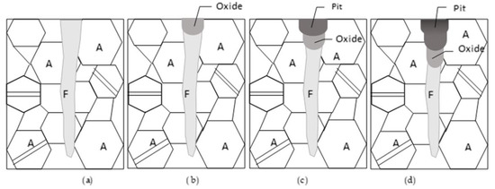
Figure 13.
Mechanism of selective corrosion destruction of AISI 321 steel (upon Figure 8) through oxidation of the δ-ferrite (A—austenite, F—δ-ferrite). (a) scheme of microstructure; (b) oxidation of the surface; (c) corrosion pit formation; (d) corrosion pit growth in depth.
Kong D. et al. [2] found that the corrosion resistance of SLM-produced AISI 316L steel in SBF is higher than that of quenched steel due to the thicker passive film. It was revealed that the high number of sub-grains and the high dislocation density at the sub-grain boundaries in the laser-melted layers promote passive layer formation [3,25]. It should be kept in mind that the size of inclusions in the microstructure of SLM-produced AISI 316L steel (50–200 nm) is much smaller compared to as-received steel [3]. Revilla R. I. et al. [14] observed that the microstructure of SLM-fabricated 316L steel represents a 3D network of cells. The cell boundaries are enriched with Cr, Ni, Mo, Si, and Ni, which make them highly resistant to corrosion, thus limiting the spread of corrosion destruction. According to Li B. et al. [26], most of the pits are formed at the sub-grain boundaries. They found that in the case of cellular sub-grains, more grain boundaries are exposed to the corrosion media compared to the dendritic sub-grains, thus promoting further pit formation. Zhao C. et al. [27] observed that pits are initiated mainly at the melt truck boundaries. The pit development in the XZ plane (building direction) is faster compared to that in the XY plane, which could be attributed to the microstructure and dendrite orientations.
It was found in our previous investigation that laser-melted layers of AISI 321 steel show higher pitting corrosion resistance in Ringer’s solution compared to wrought steel, which is due to their more homogeneous microstructure and enhanced passive layer [20].
The microstructure of the laser-melted layer of the studied steel is characterized by a dendritic structure with fine grains on the surface (Figure 1c and Figure 14a,b). It is a two-phase microstructure and consists of austenite in the dendrites and δ-ferrite in the interdendritic spaces (Figure 4). Our observations have shown that after the corrosion tests, δ-ferrite is initially destroyed. After its destruction, a network of austenitic dendrites remains (Figure 12a,b and Figure 14c), which are subsequently mechanically broken off from the walls of the corrosion pit (indicated by an arrow in Figure 12a and Figure 14d). Since δ-ferrite is distributed homogeneously in the interdendritic spaces, the resulting pits are equiaxed and shallow, with rough walls and a cellular-like structure at the bottom (Figure 14d). In case of grains with the same orientation on the surface (yellow grains 1 and 2 in Figure 14a), corrosion failure of the type shown in Figure 11a,b will occur.
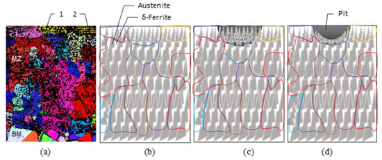
Figure 14.
Mechanism of selective corrosion of laser melted layer of AISI 321 steel upon Figure 10b: (a) Grains orientation in MZ; (b) Schematically presented microstructure of MZ; (c) Destruction of the δ-ferrite and network of austenitic dendrites; (d) Pit formed after destruction of the austenitic dendrites.
Comparisons of the corrosion pits based on the size and orientation of the grains on the laser-melted surface show that the shape and depth of corrosion damage very closely match the shape of the grains (Figure 11 and Figure 14). On the one hand, the lower thickness of the surface grains due to the high cooling rate during laser melting leads to lower depth in the corrosion pits. On the other hand, the corrosion-resistant cell boundaries in the laser-melted layers could limit the depth of corrosion pit development [14].
In the present study, a relationship between corrosion pit development and dendrite orientation is observed (Figure 12). If the dendrite axes are perpendicular or inclined toward the surface, more sub-grain boundaries (δ-ferrite here) can be exposed to the corrosive environment [26], resulting in destruction of the type shown in Figure 12b and Figure 14d. In the case of dendrite axes running parallel to the surface, pits develop along the MZ/BM boundary, mainly through the HAZ (Figure 12a), due to the higher δ-ferrite quantity [19], leading to lower corrosion resistance in this zone [23].
5. Conclusions
We investigated the morphology and microstructure of the surface layer of wrought and laser-melted AISI 321 austenitic stainless steel before and after an electrochemical corrosion test in Ringer’s solution. The two main findings of our previous research [30] were confirmed: (1) The main mechanism of corrosion destruction in the untreated and laser-melted AISI 321 austenitic stainless steel is identical, i.e., the selective destruction of the phase with the lower corrosion resistance (δ-ferrite) in the form of pits. (2) The morphology and size of the corrosion pits are different, which is determined by the morphology of δ-ferrite in the microstructure.
The following can be concluded from the present study:
- The mechanism behind corrosion destruction in laser-melted layers of AISI 321 steel in Ringer’s solution is proposed and proven through our investigation. It consists of the following stages: (1) the initial destruction of the δ-ferrite; (2) the formation of an austenitic dendrite network; (3) the mechanical fracture of the austenitic dendrites and pit formation; and (4) the growth of the pit inside the grain following the previous steps.
- A relationship between corrosion pit development and dendrite orientation in the laser-melted layers is observed: (1) In the MZ, where the dendrite axes are perpendicular to or inclined toward the surface, the corrosion pit grows within the grain. (2) At the MZ/BM boundary, the dendrite axes are parallel to the surface and the corrosion pit develops through the HAZ along the MZ/BM boundary.
From the perspective of increasing resistance to corrosion destruction in the product/implant itself, more favorable conditions are created after the surface treatment of AISI 321 steel via laser melting.
Author Contributions
Conceptualization, T.D.; methodology, T.D.; software, T.D.; validation, N.P.; formal analysis, T.D.; investigation, T.D. and N.P.; resources, T.D. and N.P.; data curation, N.P.; writing—original draft preparation, T.D. and N.P.; writing—review and editing, T.D.; visualization, T.D. and N.P.; supervision, T.D.; project administration, T.D.; funding acquisition, T.D. and N.P. All authors have read and agreed to the published version of the manuscript.
Funding
This research was funded by the European Union-NextGenerationEU, through the National Recovery and Resilience Plan of the Republic of Bulgaria, project № BG-RRP-2.004-0009-C02.
Data Availability Statement
Data are contained within the article.
Conflicts of Interest
The authors declare no conflicts of interest.
Abbreviations
The following abbreviations are used in this manuscript:
| A | Austenite |
| AMT | Additive manufacturing technologies |
| AS | Artificial saliva |
| BM | Base metal |
| CW | Continuous wave |
| DLD | Direct laser deposition |
| DMLS | Direct metal laser sintering |
| EBSD | Evaluated by electron back-scattered diffraction |
| EDS | Energy dispersive spectroscopy |
| HAZ | Heat affected zone |
| LMD | Laser metal deposition |
| LML | Laser melted layers |
| LOF | Lack of fusion |
| LRM | Laser rapid manufacturing |
| MZ | Melted zone |
| OM | Optical microscopy |
| SBF | Simulated body fluids |
| SEM | Scanning electron microscopes |
| SLM | Selective laser melting |
References
- Agrawal, C.M.; Ong, J.L.; Appleford, M.R.; Mani, G. Introduction to Biomaterials: Basic Theory with Engineering Applications; Cambridge University Press: Cambridge, UK, 2014; p. 402. [Google Scholar]
- Kong, D.; Ni, X.; Dong, C.; Lei, X.; Zhang, L.; Man, C.; Li, X. Bio-functional and anti-corrosive 3D printing 316L stainless steel fabricated by selective laser melting. Mater. Des. 2018, 152, 88–101. [Google Scholar] [CrossRef]
- Man, C.; Dong, C.; Liu, T.; Kong, D.; Wang, D.; Li, X. The enhancement of microstructure on the passive and pitting behaviors of selective laser melting 316L SS in simulated body fluid. Appl. Surf. Sci. 2019, 467, 193–205. [Google Scholar] [CrossRef]
- Ko, G.; Kim, W.; Kwon, K.; Lee, T.K. The corrosion of stainless steel made by additive manufacturing: A review. Metals 2021, 11, 516. [Google Scholar] [CrossRef]
- Kathuria, Y.P. Laser microprocessing of metallic stent for medical therapy. J. Mater. Process. Technol. 2005, 170, 545–550. [Google Scholar] [CrossRef]
- Meng, H.; Liao, J.; Zhou, Y.; Zhang, Q. Laser micro-processing of cardiovascular stent with fiber laser cutting system. Opt. Laser Technol. 2009, 41, 300–302. [Google Scholar]
- Muhammad, N.; Whitehead, D.; Boor, A.; Li, L. Comparison of dry and wet fibre laser profile cutting of thin 316L stainless steel tubes for medical device applications. J. Mater. Process. Technol. 2010, 210, 2261–2267. [Google Scholar] [CrossRef]
- Alhajhamoud, M.; Candan, L.; Ilgaz, M.A.; Cinar, I.; Ozbey, S.; Čorović, S.; Kayahan, E. Laser welding of 316L austenitic stainless steel in an air and a water environment. Materials 2022, 15, 2248. [Google Scholar] [CrossRef]
- Baldissin, D.; Baricco, M.; Battezzati, L. Microstructures in rapidly solidified AISI 304 interpreted according to phase selection theory. Mater. Sci. Eng. A 2007, 449, 999–1002. [Google Scholar] [CrossRef]
- Chikarakara, E.; Naher, S.; Brabazon, D. Analysis of microstructural changes during pulsed CO2 laser surface processing of AISI 316L stainless steel. Adv. Mater. Res. 2011, 264, 1401–1408. [Google Scholar] [CrossRef]
- Khalfallah, I.Y.; Rahoma, M.N.; Abboud, J.H.; Benyounis, K.Y. Microstructure and corrosion behavior of austenitic stainless steel treated with laser. Opt. Laser Technol. 2011, 43, 806–813. [Google Scholar] [CrossRef]
- Ahmed, N.; Barsoum, I.; Haidemenopoulos, G.; Al-Rub, R.A. Process parameter selection and optimization of laser powder bed fusion for 316L stainless steel: A review. J. Manuf. Process. 2022, 75, 415–434. [Google Scholar] [CrossRef]
- Panova, N.K.; Nikolova, K.T.; Dikova, T.D. Application of lasers and laser processing technologies in modern dentistry: A review. J. Chem. Technol. Metall. 2023, 58, 1116–1127. [Google Scholar] [CrossRef]
- Revilla, R.I.; Van Calster, M.; Raes, M.; Arroud, G.; Andreatta, F.; Pyl, L.; De Graeve, I. Microstructure and corrosion behavior of 316L stainless steel prepared using different additive manufacturing methods: A comparative study bringing insights into the impact of microstructure on their passivity. Corros. Sci. 2020, 176, 108914. [Google Scholar] [CrossRef]
- Liu, S.; Lee, M.; Choi, C.; Shin, K. Effect of additive manufacturing of SUS316L using selective laser melting. J. Mater. Res. Technol. 2023, 24, 9824–9833. [Google Scholar] [CrossRef]
- Eliaz, N. Corrosion of metallic biomaterials: A review. Materials 2019, 12, 407. [Google Scholar] [CrossRef]
- Adijāns, I.; Lazov, L.; Ilieva, M.; Nikolova, M.P. Investigation of the change in wettability properties and corrosion behavior of AISI 304 after laser surface texturing. J. Phys. Conf. Ser. 2023, 2487, 012040. [Google Scholar] [CrossRef]
- Zhang, P.; Liu, Z. Physical-mechanical and electrochemical corrosion behaviors of additively manufactured Cr-Ni-based stainless steel formed by laser cladding. Mater. Des. 2016, 100, 254–262. [Google Scholar] [CrossRef]
- Stavrev, D.; Dikova, T.D.; Shtarbakov, V.; Milkov, M. Laser surface melting of austenitic Cr-Ni stainless steel. Adv. Mater. Res. 2011, 264, 1287–1292. [Google Scholar] [CrossRef]
- Dikova, T.; Tsaneva, D.; Ilieva, M.; Panova, N. Electrochemical corrosion of laser melted layers of stainless steel in Ringer solution. In Proceedings of the VI-th International Metallurgical Congress “Metallurgy, Materials, Environmental (MME), Ohrid, North Macedonia, 29 May–1 June 2014. [Google Scholar]
- Dikova, T.; Tsaneva, D.; Ilieva, M.; Panova, N.; Galunska, B. Investigation of the electro-chemical corrosion of laser-melted layers of stainless steel in artificial saliva. Adv. Mater. Process. Technol. 2015, 1, 115–123. [Google Scholar] [CrossRef]
- Laleh, M.; Hughes, A.E.; Xu, W.; Haghdadi, N.; Wang, K.; Cizek, P.; Tan, M.Y. On the unusual intergranular corrosion resistance of 316L stainless steel additively manufactured by selective laser melting. Corros. Sci. 2019, 161, 108189. [Google Scholar] [CrossRef]
- Tarasov, S.Y.; Filippov, A.V.; Shamarin, N.N.; Fortuna, S.V.; Maier, G.G.; Kolubaev, E.A. Microstructural evolution and chemical corrosion of electron beam wire-feed additively manufactured AISI 304 stainless steel. J. Alloys Compd. 2019, 803, 364–370. [Google Scholar] [CrossRef]
- Kong, D.; Dong, C.; Ni, X.; Zhang, L.; Yao, J.; Man, C.; Li, X. Mechanical properties and corrosion behavior of selective laser melted 316L stainless steel after different heat treatment processes. J. Mater. Sci. Technol. 2019, 35, 1499–1507. [Google Scholar]
- Kong, D.; Dong, C.; Ni, X.; Zhang, L.; Luo, H.; Li, R.; Li, X. The passivity of selective laser melted 316L stainless steel. Appl. Surf. Sci. 2020, 504, 144495. [Google Scholar] [CrossRef]
- Li, B.; Wang, T.; Li, P.; Wang, S.; Wang, L. Selective laser melting of 316L stainless steel: Influence of Co-Cr-Mo-W addition on corrosion resistance. Metals 2021, 11, 597. [Google Scholar] [CrossRef]
- Zhao, C.; Bai, Y.; Zhang, Y.; Wang, X.; Xue, J.M.; Wang, H. Influence of scanning strategy and building direction on microstructure and corrosion behaviour of selective laser melted 316L stainless steel. Mater. Des. 2021, 209, 109999. [Google Scholar] [CrossRef]
- Zhang, Z.; Yuan, X.; Zhao, Z.; Li, X.; Liu, B.; Bai, P. Electrochemical noise comparative study of pitting corrosion of 316L stainless steel fabricated by selective laser melting and wrought. J. Electroanal. Chem. 2021, 894, 115351. [Google Scholar] [CrossRef]
- Hu, H.; Wen, S.; Duan, L.; Wang, C.; Chen, K.; Wei, Q.; Shi, Y. Enhanced corrosion behavior of selective laser melting S136 mould steel reinforced with nano-TiB2. Opt. Laser Technol. 2019, 119, 105588. [Google Scholar] [CrossRef]
- Dikova, T.; Panova, N. Corrosion failure in biological fluids of laser melted surface of AISI 321 stainless steel. Procedia Struct. Integr. 2025, 68, 99–105. [Google Scholar] [CrossRef]
- Dikova, T.D.; Panova, N.K.; Parushev, I.D. Investigation of the microstructure of AISI 321 stainless steel after laser surface melting. J. Chem. Technol. Metall. 2024, 59, 207–214. [Google Scholar] [CrossRef]
- ASTM E2627; Standard Practice for Determining Average Grain Size Using Electron Backscatter Diffraction (EBSD) in Fully Recrystallized Polycrystalline Materials. ASTM International: West Conshohocken, PA, USA, 2019.


Disclaimer/Publisher’s Note: The statements, opinions and data contained in all publications are solely those of the individual author(s) and contributor(s) and not of MDPI and/or the editor(s). MDPI and/or the editor(s) disclaim responsibility for any injury to people or property resulting from any ideas, methods, instructions or products referred to in the content. |
© 2025 by the authors. Licensee MDPI, Basel, Switzerland. This article is an open access article distributed under the terms and conditions of the Creative Commons Attribution (CC BY) license (https://creativecommons.org/licenses/by/4.0/).