Abstract
In-wheel motor (IWM)-driven electric vehicles (EVs) are susceptible to road excitation, which can induce eccentricity between the stator and rotor of the IWM. This eccentricity leads to unbalanced electromagnetic forces (UEFs) and electromechanical coupling (EMC) effects, severely degrading vehicle dynamic performance. To address this issue, this study first established an EMC system model encompassing UEF, IWM drive, and vehicle dynamics. Based on this model, four typical operating conditions—constant speed, acceleration, deceleration, and steering—were designed to thoroughly analyze the influence of EMC effects on vehicle dynamic response characteristics. The analysis results were validated through real-vehicle experiments. The results indicate that the EMC effects caused by motor eccentricity primarily affect the vehicle’s vertical dynamics performance (especially during acceleration and deceleration), leading to increased vertical body acceleration and reduced ride comfort, while having a relatively minor impact on longitudinal and lateral dynamics performance. Additionally, these effects significantly increase the relative eccentricity of the motor under various operating conditions, further degrading motor performance. To mitigate these negative effects, this paper designs an active suspension controller based on distributed model predictive control (DMPC). Simulation and experimental validation demonstrate that the proposed controller effectively improves ride comfort and body posture stability while significantly suppressing the growth of the motor’s relative eccentricity, thereby enhancing motor operational performance.
1. Introduction
As the forefront of the transformation of the automobile industry, EVs have become the core carrier of future transportation [1,2,3]. Among them, IWM-driven EV integrates the drive motor into the wheel hub and directly drives the wheel through the motor, enabling independent control of individual wheels. It offers technical advantages such as high space utilization rate, high power transmission efficiency, and flexible handling response [4,5,6,7], thus attracting significant attention. However, external disturbances such as road excitation and driver operation inevitably cause eccentricity in the air gap of the IWM. This leads to an unbalanced air gap magnetic field distribution and UEF. This phenomenon not only aggravates motor vibration but also induces negative coupling effects between the electromagnetic field and the mechanical field, thereby ultimately degrading vehicle ride comfort [8,9,10].
In order to alleviate the degradation of vehicle dynamic performance caused by the IWM, existing research primarily focuses on the analysis of the influence mechanism of UEF and the development of vehicle dynamic control strategies. Regarding the analysis of the influence mechanism of UEF, Li et al. explored the excitation characteristics of these forces and analyzed their impact on the vehicle’s vertical dynamic performance from the perspectives of vibration energy distribution and dynamic transmission characteristics, finding that UEF significantly degrade vehicle ride comfort [11]. Qin et al. investigated the effects of factors such as driving speed, road grade, and tire vertical load on the vibration response characteristics of IWM-driven EVs [12]. Their results showed that increases in road grade and driving speed deteriorate both the vertical performance of the suspension and the operational performance of the motor. Wu et al. established a mechanical-electrical-magnetic multi-field coupling model and analyzed the coupling mechanism between IWM air gap eccentricity and UEF [13,14]. Their results indicate that air gap eccentricity and UEF interact and mutually reinforce each other, further intensifying the multi-field coupling effect and forming a self-amplifying cycle. Based on an integrated system combining in-wheel direct drive and air suspension, Li et al. analyzed the influence of road excitation and UEF on vehicle longitudinal and vertical dynamics in different frequency domains [15]. Their findings reveal that UEF exert the greatest influence on vehicle dynamic performance within the 40 Hz frequency band.
The above research mainly focused on the single steady-state condition of constant speed, ignoring the influence of different driving conditions such as acceleration and braking on the vehicle’s vertical dynamic response and the IWM’s operational performance. Hu et al. analyzed the impact of UEF on dynamic performance under acceleration and deceleration conditions [16]. They found that during acceleration and braking, the larger phase currents and changing motor speeds significantly increase the UEF, thereby degrading vehicle comfort. Li et al., based on a field-oriented control model with variable switching frequency, established a longitudinal-vertical coupled dynamic model and analyzed the vehicle’s dynamic performance during the acceleration phase in the time-frequency domain [17]. Their results demonstrated that the vehicle body acceleration significantly increases in the low-frequency region while exhibiting minimal change in the high-frequency region. Furthermore, during vehicle steering maneuvers, UEF directly act on the wheels, affecting the tire dynamic load, deteriorating the tire-road contact, increasing the risk of vehicle roll and even rollover, and consequently reducing driving safety [18]. Tan et al. constructed an 11-degree-of-freedom coupled dynamic model to explore the influence of UEF on the vehicle’s lateral-vertical coupled dynamic performance [19]. Their results revealed that UEF cause vehicle performance deterioration under any operating condition. Building upon the analysis of motor horizontal eccentricity, Deng et al. analyzed the characteristics of UEF under motor tilted eccentricity and investigated the influence mechanism of unbalanced electromagnetic torque on the lateral stability of IWM -driven EVs [20]. They discovered that tilted eccentricity leads to deteriorated handling stability, compromising driving safety.
On the basis of clarifying the mechanism of the EMC effect caused by UEF, many scholars suppress the negative effects of vibration through active suspension. Li et al. proposed a multi-objective optimization control method for active suspension based on a quarter-vehicle model [11]. This method constrains IWM eccentricity within a reasonable range using active suspension control, effectively reducing the sensitivity of the vehicle system to electromagnetic excitation, and significantly improving the ride comfort and wheel-ground contact of IWM-driven EVs. Aiming at the problem of vehicle vertical vibration aggravated by the EMC effect, Wu et al. designed a robust preview control strategy under the framework of a half-car model [21]. This strategy effectively suppressed the EMC effect of the rear IWM and improved ride comfort. Yu et al. proposed a quasi-infinite horizon nonlinear model predictive control for air suspension based on a full-vehicle model [22]. This controller can handle the nonlinear constraints of damping force, effectively suppress the vibration of both the sprung mass and the IWM, and improve the longitudinal and vertical dynamic performance of the vehicle.
Decentralized coordinated control is based on independent decision-making and local information interaction of each subsystem. With its excellent control performance, effective constraint handling ability and structural flexibility, it has significant advantages in the control of large-scale complex systems. Zhang et al. proposed a distributed coordinated control method for autonomous surface vehicles using event-triggered mechanisms and neural predictors to address unknown kinetics and enhance containment formation performance, with simulation results demonstrating the effectiveness of the approach [23]. Liang et al. proposed a decentralized coordinated control framework based on a multi-agent system, achieving coordinated control between the active front steering system and the active suspension system, thereby significantly improving vehicle lateral stability and ride comfort [24]. Zhang et al. introduced a distributed model predictive control strategy for active suspension systems optimized by a radial basis function neural network, which effectively reduced the vehicle’s vertical acceleration, pitch angular acceleration, and roll angular acceleration through coordinated control among suspension subsystems [25].
Based on the above, significant limitations persist in existing research. On the one hand, most findings are focused on constant speed conditions, with insufficient exploration of the vehicle’s vertical dynamic response mechanisms under transient driving conditions such as acceleration, braking, and steering. On the other hand, the majority of existing studies are conducted under constant IWM relative eccentricity or constant UEF excitation amplitude/frequency, failing to account for the dynamic coupling effect between the motor and the vehicle system during actual driving, which cannot accurately reflect the true state of IWM-driven EVs. Additionally, existing research on active suspension control for suppressing negative vibration effects predominantly employs simplified models (such as quarter-vehicle and half-car models). Even when full-vehicle models are used, the high system order poses significant difficulties in structural complexity, parameter optimization, and real-time computation, compromising practicality. To address these research gaps, this paper aims to: construct an EMC system model for IWM-driven EVs incorporating a PMSM UEF calculation model, an IWM drive system model, and a vehicle dynamics system model; systematically reveal the influence mechanism of UEF on vehicle dynamic performance under constant speed, uniform acceleration, uniform deceleration, and uniform high-speed steering conditions; and propose a distributed model predictive control (DMPC) strategy for the full-vehicle suspension model, effectively suppressing negative vibration effects. The remainder of this paper is structured as follows: Section 2 constructs the EMC system model for the IWM-driven EV; Section 3 analyzes the influence of UEF on vehicle dynamic performance under different operating conditions; Section 4 designs real-vehicle experiments to validate the effectiveness of the developed model; Section 5 designs the DMPC-based active suspension controller; finally, Section 6 concludes the paper.
2. Coupling Model Establishment
2.1. Unbalanced Electromagnetic Force Model
In this paper, the UEF calculation model for an outer-rotor in-wheel PMSM is established based on the analytical method. A 51-slot/23-pole outer-rotor PMSM is employed. The relevant parameters are shown in Table A1. Only the principal formulas are presented herein; detailed derivations can be found in References [26,27,28,29]. The air gap magnetic field of the PMSM comprises the no-load magnetic field generated by the permanent magnets and the armature reaction magnetic field produced by the stator windings. Under the condition of unsaturated air gap magnetic field, the radial and tangential components of the air gap magnetic field, neglecting the influence of stator slotting, can be obtained by the linear superposition of the no-load field and the armature reaction field :
In the equations, and are the no-load radial magnetic field and tangential magnetic field neglecting the slotting effect; and are the resultant radial magnetic field and tangential magnetic field of the armature reaction neglecting the slotting effect; denotes the radial position in the polar coordinate system; is the corresponding angular coordinate; represents time.
Furthermore, to account for the influence of stator slotting on the air gap magnetic field, the complex relative permeability coefficients and are introduced to modify the model [30]. The analytical expressions of the air gap radial magnetic field and the tangential magnetic field considering the influence of slotting are as follows:
During vehicle operation, the vertical excitation acting on the wheels is the most significant, which can readily cause the stator to deviate from the rotational center, resulting in static eccentricity. Therefore, static eccentricity is selected as the eccentricity type for this study. Static eccentricity of an IWM refers to a situation where the stator develops an eccentricity in a certain direction, while the rotor’s center of rotation remains in its original position. To simplify the research, it is assumed that the eccentricity direction of the IWM stator is vertical, as shown in Figure 1. In the figure, represents the geometric center of the rotor, represents the geometric center of the stator, and denotes the static eccentricity between the stator and rotor in the vertical direction.
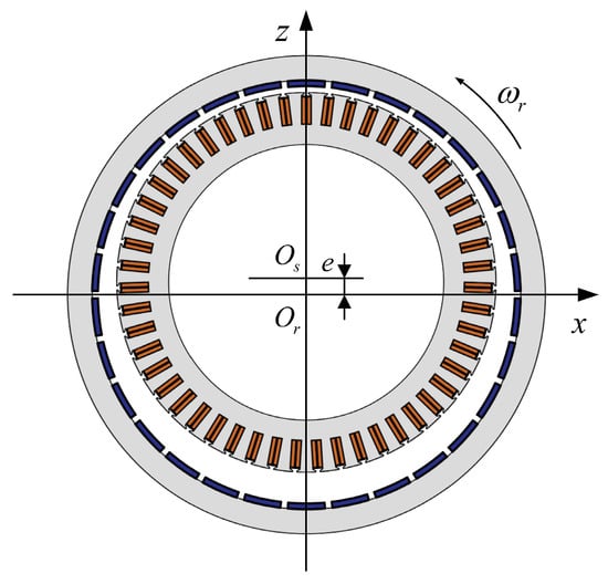
Figure 1.
Static eccentricity form of the IWM stator and rotor.
The eccentric air gap length of the IWM is a function of the angular position , expressed as:
where is the effective air gap length of the non-eccentric IWM, .
The permeability distribution function of the IWM under static eccentricity is given by:
where is the effective eccentricity ratio, and is the permeability correction coefficient under static eccentricity.
Multiplying the slotted model mentioned above by the permeability correction coefficient yields the air gap radial magnetic field and the tangential magnetic field incorporating the eccentricity effect:
Based on this, the radial electromagnetic force wave and tangential electromagnetic force wave under static eccentricity are calculated using the Maxwell tensor method:
Finally, the electromagnetic force wave is integrated over the circumference and decomposed into the vertical direction to obtain the radial UEF of the motor:
where is the axial length of the IWM.
2.2. In-Wheel Motor and Its Drive Model
In this paper, to accurately reflect the coupling relationship between the electromagnetic excitation of the IWM and the vehicle dynamics, an IWM-drive system model is established to provide the electromagnetic torque for vehicle propulsion and the phase current required to generate the UEF. The three-phase windings of the IWM are star-connected. The voltage equation of the IWM is as follows [31]:
where and correspond to the phase voltage and phase current of the three-phase windings, respectively; is the resistance of each phase winding of the stator; and are the winding self-inductance and mutual inductance respectively; is a first-order differential operator; and is the back electromotive force of the three-phase windings.
To accurately track the ideal driving speed and obtain a more precise drive current, and building upon the traditional dual-loop PI control, the inner current loop is replaced with a deadbeat predictive current control (DPCC) strategy, which offers superior dynamic performance and reduced harmonic current [32,33,34]. The voltage equation at time is as follows:
where and are the predicted d-axis and q-axis currents (A) at time ; and are the ideal output voltages (V) for the d-axis and q-axis at time ; and are the d-axis and q-axis currents (A) sampled at time ; is the electrical angular velocity (rad/s) at time ; is the flux linkage (Wb) of the motor. The nominal parameters of the IWM in this study are shown in Table A2.
2.3. Vehicle Dynamics Model
In order to comprehensively study the influence of UEF on the longitudinal-transverse-vertical dynamic performance of the vehicle, an 18-degree-of-freedom (18-DOF) vehicle dynamics model is established as shown in Figure 2, which mainly includes vehicle lateral, longitudinal, yaw motion, body roll, pitch, vertical motion, vertical motion of the motor part, and vertical and rotational motion of the wheel.
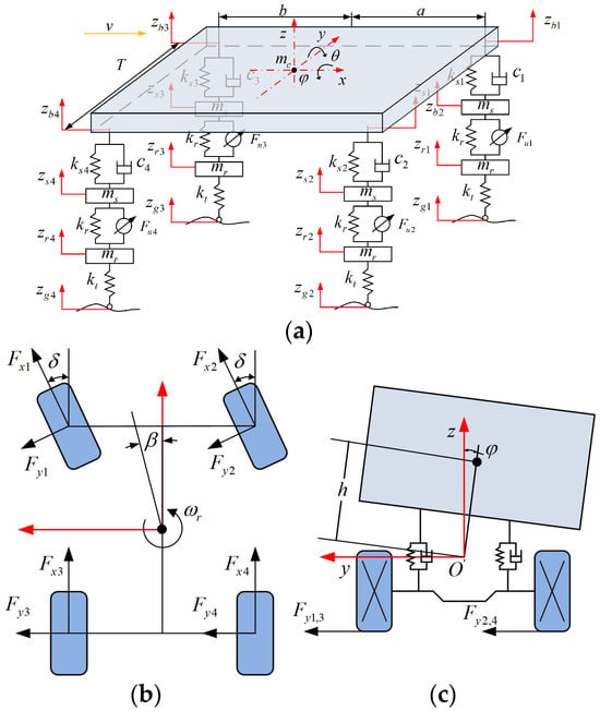
Figure 2.
18-DOF vehicle dynamics model: (a) Vehicle vertical model; (b) Vehicle lateral and yaw model; (c) Body roll model.
Based on Newton’s laws of motion, the vehicle dynamics equations are derived as follows:
① Vehicle Longitudinal Motion Equation:
where and are the rolling resistance and air resistance respectively.
② Vehicle Lateral Motion Equation:
③ Vehicle Yaw Motion Equation:
④ Body Vertical Motion Equation (Bounce):
where is the active force of each suspension, and is the vertical force of each suspension, specified as follows:
where is the vertical displacement at the four endpoints of the body, specified as follows:
⑤ Body Pitch Motion Equation:
⑥ Body Roll Motion Equation:
⑦ Vertical Motion Equation of Each IWM Stator Part:
⑧ Vertical Motion Equation of Each IWM Rotor Part:
⑨ Rotational Motion Equation of Each Wheel:
where the vertical load on each wheel of the vehicle is:
All parameters of the full-vehicle model studied in this paper are listed in Table A3.
Tire is the only medium for the interaction between the vehicle and the ground. In order to accurately reflect the interaction between the tire and the ground during the driving of the vehicle, it is necessary to construct an accurate tire model. In this paper, the magic formula tire model is selected. The model uses a combination of trigonometric functions to fit the tire characteristics. The general expression is:
The detailed formulas and parameters are shown in References [35,36].
2.4. Construction of Electromechanical Coupling System Model
Based on the above UEF model of the PMSM, the IWM-drive model, and the vehicle dynamics system model, an EMC system model for IWM-driven EVs is constructed, as illustrated in Figure 3. When the vehicle is in motion, the IWM-drive system first calculates the required motor torque and the ideal current based on the current vehicle speed and the desired speed. Subsequently, the road excitation model generates road excitation corresponding to the vehicle speed, which acts upon the vertical dynamics system. The vertical dynamics system of the vehicle then undergoes forced vibration under this road excitation, resulting in a relative eccentricity between the stator and rotor of the IWM. Finally, the UEF model of the PMSM generates a corresponding vertical UEF based on this motor relative eccentricity, which continues to act on the vehicle dynamics system. This vertical UEF acts directly on the wheel system, leading to a change in the vertical load. Consequently, the longitudinal force and lateral force generated by the tire model act upon the longitudinal dynamics system and the lateral dynamics system respectively. This model comprehensively accounts for the influence of the vehicle’s driving state on the output of both the drive system and the UEF, as well as the mutual coupling between motor eccentricity and the UEF. It can accurately describe the dynamic coupling relationships among different vehicle subsystems and realistically reflect the vehicle’s longitudinal and vertical dynamic and kinematic states.
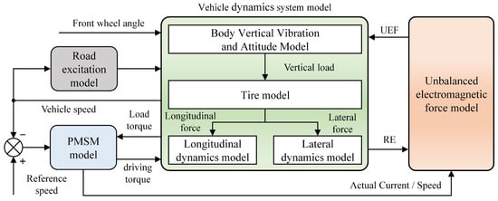
Figure 3.
EMC System Model Architecture of IWM-Driven EV.
3. Vehicle Dynamic Response Analysis
In order to clarify the influence of UEF on vehicle dynamic performance under different operating conditions, the following four conditions are formulated for analysis:
① Constant speed condition
② Uniform acceleration condition
③ Uniform deceleration condition
④ Uniform high-speed steering condition
For straight-line driving conditions, the body vibration acceleration (BVA), suspension deflection (SD), tire dynamic load (TDL), relative eccentricity (RE), body pitch angle (BPA), and body roll angle (BRA) are selected as the system response outputs. For the steering condition, the yaw rate, sideslip angle, and rollover critical factor (RCF) are additionally selected as system response outputs.
The RCF is expressed as follows:
where . A larger RCF indicates a greater possibility of vehicle rollover.
3.1. Constant Speed Condition
Figure 4 demonstrates the dynamic response of the vehicle operating at a constant speed of 20 m/s on a B-class road surface. In the figure, the label with UEF indicates that the EMC effect is considered, while without UEF signifies that the EMC effect is neglected. It can be observed that when the EMC effect is considered, both the relative eccentricity and the UEF of the motor stator and rotor are significantly higher compared to the case where the EMC effect is ignored. The reason for this is that when the EMC effect is neglected, the variation in the relative eccentricity between the stator and rotor is solely caused by the relative motion between the wheel and the suspension induced by road excitation. Due to the high stiffness of the motor bearing, this variation remains small, resulting in a relatively minor UEF generated by the IWM. In contrast, when the EMC effect is considered, the UEF generated by the eccentricity between the stator and rotor weakens the effective support stiffness of the bearing. This degradation in stiffness leads to a further increase in the relative eccentricity. The increased eccentricity, in turn, amplifies the UEF, which continues to undermine the stability of the motor’s air gap, thereby forming a vicious cycle where the relative eccentricity and the UEF mutually exacerbate each other.
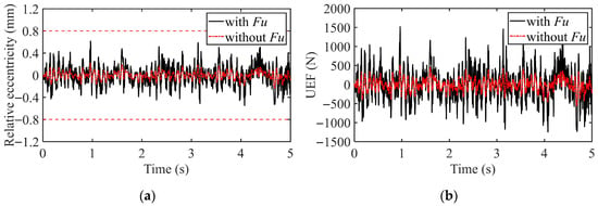
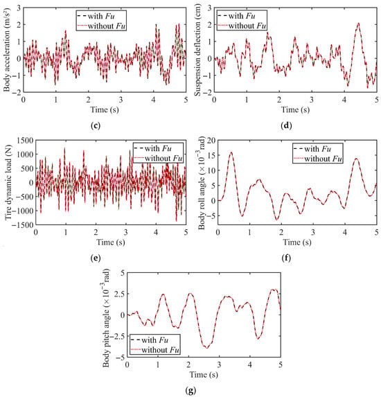
Figure 4.
Vehicle dynamic response under constant speed condition: (a) Relative eccentricity; (b) Unbalanced electromagnetic force (UEF); (c) Body vibration acceleration; (d) Suspension deflection; (e) Tire dynamic load; (f) Body roll angle; (g) Body pitch angle.
Furthermore, although the UEF increases significantly, its impact on the suspension deflection, body roll angle, and pitch angle is very limited, with the response curves under the two excitation conditions being nearly identical. However, the body vibration acceleration and tire dynamic load are slightly affected: when the EMC effect is considered, the peak responses of both are slightly reduced.
Figure 5 shows the variation trend of the root mean square (RMS) values of the vehicle’s dynamic responses while driving at constant speeds of 5, 10, 15, and 20 m/s on a B-class road surface. It can be observed that at low speeds, the motor drive torque balances the motion resistance torque, primarily overcoming the rolling resistance torque caused by ground friction, resulting in a relatively small required torque. This lower torque demand corresponds to reduced input current, thereby generating a smaller UEF. Under these conditions, the EMC effect has a minor influence on vehicle dynamic performance. However, as vehicle speed increases, the impact of the vertical UEF becomes more pronounced, primarily reflected in the tire dynamic load. Since the UEF weakens the support stiffness of the motor bearing, the tire dynamic load under EMC consideration is even slightly lower than that under road excitation alone. In contrast, the body vibration acceleration, pitch angular acceleration, and suspension deflection show no significant changes. Notably, the increase in vehicle speed leads to a substantial rise in the relative eccentricity of the IWM stator and rotor, indicating considerable degradation in motor operational stability. Therefore, under this driving condition, close attention must be paid to the variation in relative eccentricity to ensure motor operational stability and safety.
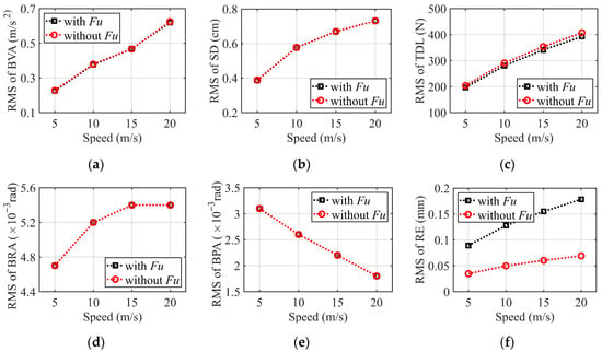
Figure 5.
The RMS value of vehicle dynamic response under constant speed condition: (a) Body vibration acceleration; (b) Suspension deflection; (c) Tire dynamic load; (d) Body roll angle; (e) Body pitch angle; (f) Relative eccentricity.
3.2. Uniform Acceleration Condition
To investigate the variation of the UEF under uniform acceleration conditions and its impact on vehicle dynamic performance, the following simulation scenario is established: the vehicle accelerates uniformly from a standstill to 5 m/s at an acceleration of 1 m/s2 between 0–5 s, and then continues to travel at a constant speed of 5 m/s for 1 s before the simulation ends.
Figure 6 presents the relative eccentricity and the UEF of the left-front IWM under this simulation condition. Analysis of the variation trends of the relative eccentricity and the UEF reveals that during the period of 1.5–2.5 s, the motor’s UEF deteriorates sharply. Simultaneously, the relative eccentricity between the motor stator and rotor increases rapidly, with its peak value even exceeding the air gap boundary. This phenomenon fully demonstrates that when the EMC effect is considered under uniform acceleration conditions, the rapid deterioration of the UEF causes the relative eccentricity to severely exceed the permissible limit. This significantly compromises the operational stability of the IWM and substantially increases the risk of friction and collision between the stator and rotor, as well as accelerated motor wear.
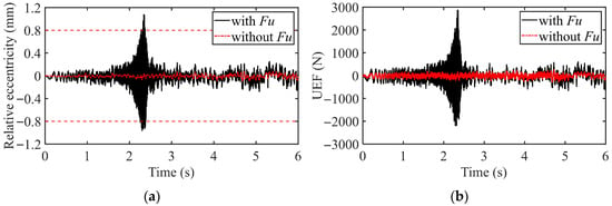
Figure 6.
UEF and relative eccentricity of the IWM under uniform acceleration condition: (a) Relative eccentricity; (b) Unbalanced electromagnetic force (UEF).
Figure 7 presents the vehicle dynamic response curves under the aforementioned uniform acceleration condition. It is clearly observed that during the acceleration process, due to the UEF of the motor, the vehicle’s body vibration acceleration and tire dynamic load deteriorate significantly within the 1.5–2.5 s period. Among these, the deterioration of the body vibration acceleration is particularly severe, with its amplitude deteriorating by more than 100% compared to the maximum deterioration observed without considering the EMC effect. Consistent with the conclusion under constant-speed conditions, the suspension deflection is relatively less affected by the UEF, exhibiting only minor deterioration in amplitude within the 1.5–2.5 s interval. In contrast, the body pitch angle and roll angle remain almost unaffected. Furthermore, observation of the longitudinal acceleration reveals that its fluctuation generally intensifies with increasing vehicle speed. It is particularly noteworthy that during the 2–2.5 s period, the fluctuation amplitude of the longitudinal acceleration is significantly larger when the EMC effect is considered.
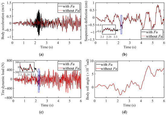
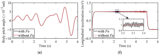
Figure 7.
Vehicle dynamic response under uniform acceleration condition: (a) Body vibration acceleration; (b) Suspension deflection; (c) Tire dynamic load; (d) Body roll angle; (e) Body pitch angle; (f) Longitudinal acceleration.
Figure 8 further presents the variation trend of the RMS values of the vehicle’s dynamic responses during different acceleration phases, including 0–5 m/s, 5–10 m/s, 10–15 m/s, and 15–20 m/s, with a constant acceleration of 1 m/s2 in each phase. It can be observed that the deterioration in vehicle dynamic performance induced by the UEF primarily occurs in the 0–5 m/s acceleration phase. During this stage, both the body vibration acceleration and the relative eccentricity deteriorate significantly. As the vehicle speed continues to increase, the influence of the UEF on the body vibration acceleration gradually diminishes; however, it continues to exert a considerable effect on the relative eccentricity. Furthermore, the rest of the vertical dynamic performance of the vehicle is not obviously affected by the vertical unbalanced electromagnetic force during the whole acceleration process.
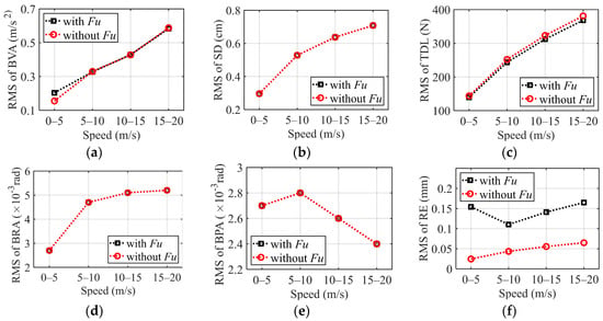
Figure 8.
The RMS value of vehicle dynamic response under uniform acceleration condition: (a) Body vibration acceleration; (b) Suspension deflection; (c) Tire dynamic load; (d) Body roll angle; (e) Body pitch angle; (f) Relative eccentricity.
3.3. Uniform Deceleration Condition
To further investigate the influence of the UEF on both vehicle and motor performance during braking, a dynamic simulation was conducted under a uniform deceleration braking condition.
Figure 9 illustrates the variation trend of the RMS values of the vehicle’s dynamic responses at a deceleration of 1 m/s2 across different braking phases: 20–15 m/s, 15–10 m/s, 10–5 m/s, and 5–0 m/s. The results indicate that the output response under braking conditions is similar to that under acceleration. The influence of the UEF on vehicle dynamic response and motor performance also predominantly occurs during the low-speed braking stage (5–0 m/s). Notably, the EMC effect is more pronounced under pure electric motor braking conditions, leading to a more significant deterioration in motor performance.
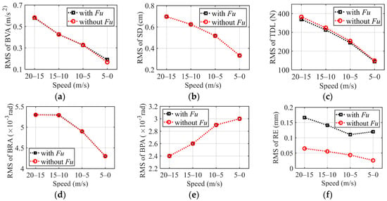
Figure 9.
The RMS value of vehicle dynamic response under uniform deceleration condition: (a) Body vibration acceleration; (b) Suspension deflection; (c) Tire dynamic load; (d) Body roll angle; (e) Body pitch angle; (f) Relative eccentricity.
3.4. Uniform High-Speed Steering Condition
To further investigate the influence of variations in the motor’s UEF on both vehicle and IWM performance during steering maneuvers, a dynamic simulation under the fishhook condition was conducted. During the simulation, the front wheel steering angle input is illustrated in Figure 10, and the vehicle speed was maintained at 20 m/s.
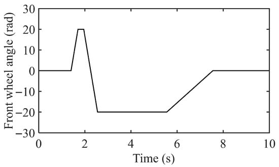
Figure 10.
Front wheel angle.
Figure 11 presents the relative eccentricity and UEF of the left-front IWM under this simulation condition. It is evident from the figure that the dynamic load transfer occurring during steering (where the load on the outer wheels increases and the load on the inner wheels decreases) significantly compromises the air gap uniformity between the IWM stator and rotor. This load redistribution induces an increase and shift in the relative eccentricity. The increased eccentricity, in turn, further excites a rise and lateral shift in the vertical UEF. Notably, during this process, the peak value of the relative eccentricity exceeds the motor air gap boundary multiple times. This not only disrupts the normal operational state of the motor but also substantially aggravates abnormal contact and friction between the stator and rotor, significantly accelerating the motor wear process and consequently shortening the motor service life.

Figure 11.
UEF and relative eccentricity of the IWM under uniform high-speed steering condition: (a) Relative eccentricity; (b) Unbalanced electromagnetic force (UEF).
Figure 12 shows the vehicle dynamic response curves under this condition. It is clearly observed that the body vibration acceleration experiences slight deterioration within the 3–3.5 s interval. Consistent with previous analyses, vertical dynamic performance indicators such as suspension deflection, body pitch angle, roll angle, and tire dynamic load show no significant influence from the UEF throughout the entire process. Furthermore, key parameters characterizing vehicle lateral stability—including yaw rate, sideslip angle, and critical rollover factor—exhibit nearly identical response curves in simulation results, regardless of whether the EMC effect is considered or ignored. The underlying reason, as noted earlier, is that the tire dynamic load does not change substantially. According to Equation (25), this implies that the vertical tire load remains stable. Since the vertical load is the fundamental determinant of tire longitudinal and lateral forces, there is no significant difference in tire force generation. As a result, the yaw moment balance and directional stability of the vehicle remain largely unaffected by the vertical UEF. In summary, under steering conditions, the influence of the vertical UEF generated by the IWM is primarily confined to localized and transient disturbances in body vibration acceleration, while its impact on overall vertical dynamic balance and lateral stability—including handling and anti-rollover performance—is weak and even negligible.
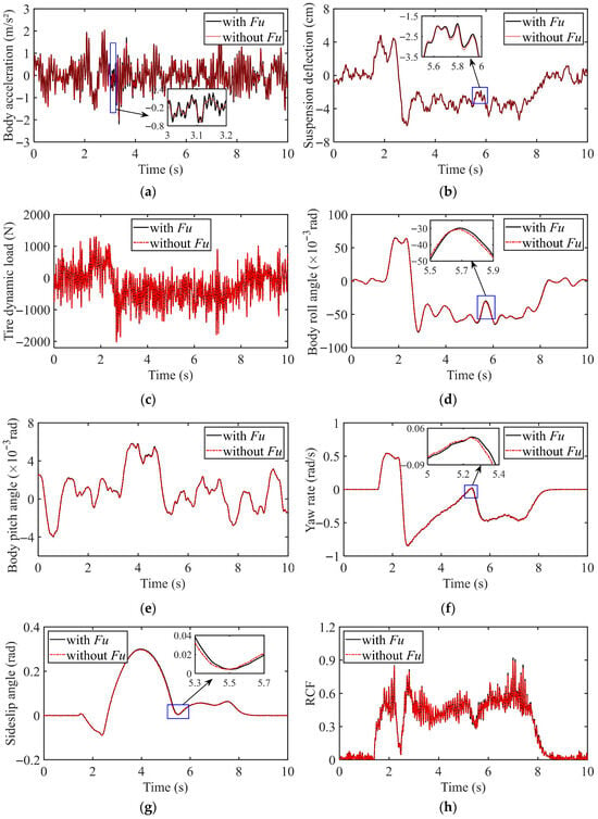
Figure 12.
Vehicle dynamic response under uniform high-speed steering condition: (a) Body vibration acceleration; (b) Suspension deflection; (c) Tire dynamic load; (d) Body roll angle; (e) Body pitch angle; (f) Yaw rate; (g) Sideslip angle; (h) Rollover critical factor (RCF).
In summary, the influence of the UEF generated by the IWM on vehicle dynamics is primarily concentrated on the vertical dynamic performance. The underlying reason is that the UEF weakens the bearing stiffness, leading to an increase in eccentricity. This increased eccentricity, in turn, further amplifies the UEF, resulting in a self-amplifying/vicious cycle that threatens motor stability and significantly deteriorates the vertical vibration of the vehicle body. Due to its limited impact on the vertical tire load, its effect on the longitudinal and lateral dynamic performance of the vehicle is negligible. Therefore, the focus of mitigating its negative effects lies in vertical control. A feasible solution is to design an active suspension control strategy that accounts for EMC effects, effectively attenuating vibrations to ensure both motor operational stability and ride comfort.
4. Experimental Verification
In order to verify the accuracy of the established EMC system model, this paper conducted real-vehicle road tests using a modified IWM-driven EV on a straight asphalt road. The test prototype car is modified from an electric vehicle. The prototype car adopts a load-bearing body, the front suspension is a McPherson structure, and the rear suspension is a torsion beam structure. In the process of modification, the wheel side system of the original vehicle is retained, that is, the suspension guiding mechanism, the steering knuckle and the wheel part, and the transmission shaft and motor of the original vehicle are removed. Four-wheel drive of IWM is adopted. The IWM is connected to the steering knuckle through the stator shaft fixture and connected to the hub through bolts. The primary test equipment and sensors included acceleration sensors (PCB333B30 piezoelectric acceleration sensor, acceleration range is −50~50 g, the maximum sampling frequency is 3000 Hz), current sensors, and LMS SCADAS data acquisition platform.
Acceleration sensors were fixed at the vehicle center of mass and the IWM stator to measure body vibration acceleration signal and vertical vibration acceleration signal of the motor stator, respectively. Additionally, a current sensor was installed in the IWM power supply circuit to acquire the real-time IWM drive current signal. Finally, all sensors are connected to the LMS data acquisition platform, and the collected signals are collected and analyzed by LMS Test.Lab V18.0 software. The test equipment and sensor layout configuration are illustrated in Figure 13.
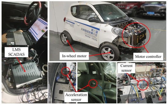
Figure 13.
IWM-drive EV dynamic system test.
Repeated tests were carried out according to the above constant speed, uniform acceleration and uniform deceleration conditions to measure the vibration acceleration of the body and the vertical vibration acceleration of the stator of the left front wheel motor. The trend of multiple test results is consistent. Figure 14 shows a set of representative comparison curves between test results and simulation results.
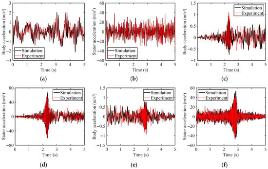
Figure 14.
Test results comparison: (a) Body acceleration under constant speed condition; (b) Stator acceleration under constant speed condition; (c) Body acceleration under uniform acceleration condition; (d) Stator acceleration under uniform acceleration condition; (e) Body acceleration under uniform deceleration condition; (f) Stator acceleration under uniform deceleration condition.
It can be observed from the figure that the experimental and simulation data for body vibration acceleration and vertical vibration acceleration of the motor stator exhibit substantial agreement in terms of overall trend, vibration period, and amplitude. Notably, a significant increase in vibration amplitude was observed in both datasets during the uniform acceleration phase (1.5–2.5 s) and the uniform deceleration phase (2.5–3.5 s). Considering factors such as wear in the suspension components and the accuracy of road profile measurement, the discrepancies between the simulation and experimental results are deemed acceptable. Therefore, these results are fundamentally consistent with the theoretical analysis. This agreement not only verifies the theoretical prediction regarding vibration intensification caused by the EMC effect during acceleration/deceleration phases but also robustly demonstrates the validity of the developed EMC system dynamics model for the IWM-driven EV.
5. Design of Active Suspension Controller Based on DMPC
The preceding mechanism analysis demonstrates that the UEF of the IWM will significantly deteriorate the vehicle body’s vertical vibration acceleration and threaten IWM stability through the vicious cycle of ‘eccentricity-electromagnetic force’, while active suspension control is an effective approach to suppress this negative effect. However, designing a centralized controller for such a high-dimensional system would be extremely complex and limited in engineering practicality. To solve this problem, this paper employs the distributed model predictive control (DMPC) algorithm, decomposing the overall system into five low-dimensional subsystems and designing a separate MPC controller for each subsystem. This method significantly simplifies the controller structure and enhances system designability and engineering practicality, while simultaneously retaining the core effectiveness of the suspension control in improving ride comfort.
5.1. Vehicle Model Decomposition
The vehicle system is divided into five subsystems, including four suspension subsystems and one body subsystem. The state variable of each suspension subsystem is selected as , the output variable is , the control variable is , and the disturbance is . The state variable of the body subsystem is , the output variable is , and the disturbance is . According to the vehicle vertical dynamics model described by Equations (17)–(23), the state-space representation of each subsystem is obtained:
Part of the matrix will be listed in Appendix B.
5.2. Design of DMPC Controller
The control objectives of this system are to minimize the vehicle body’s vertical vibration acceleration, pitch angle, and roll angle. At the same time, since the relative eccentricity between the motor stator and rotor is the key factor exciting the unbalanced electromagnetic force, it must also be minimized, while other performance metrics should be maintained within reasonable bounds. Within the DMPC framework of this study, the body subsystem is not directly controlled and is only used for state prediction. The four suspension subsystems, however, perform coordinated optimization based on the predicted states of the body subsystem. This approach effectively suppresses the relative eccentricity while significantly reducing the body’s vertical vibration acceleration, pitch angle, and roll angle, thereby achieving stable control of the vehicle body attitude. Considering the existence of parameter transfer between subsystems and the availability of some known parameters, the state equation and output equation for each suspension subsystem are formulated as follows:
Then, the optimization problem for each suspension subsystem is defined as follows:
In the equations, and are the peak output thrust of the suspension. In addition, additional constraints are added in the controller design process to prevent the suspension deflection and tire dynamic load from exceeding the upper and lower limits.
The performance index function for the overall vehicle suspension system is given by:
In the equations, and are weight matrices, and are weighting coefficients for the subsystems. The local optimization objective of all four suspension subsystems is to maintain vehicle body posture and reduce the relative eccentricity ratio, which are integrated into and serve the vehicle body subsystem. Therefore, the weighting coefficient is . Meanwhile, since the vehicle body vibration acceleration, pitch angle, roll angle, and relative eccentricity ratio are the primary optimization objectives, their weighting coefficients are increased. The weighting matrix for the vehicle body subsystem is , and the weighting matrix for the suspension subsystem are , .
This optimization problem is transformed into a standard quadratic programming (QP) problem for solution. First, the state equation is discretized:
where , is the control period. Substituting this into the output equation yields:
A prediction matrix is established:
The performance index function in Equation (32) can then be written in the following form:
Finally, quadratic programming is performed on the optimization index function to solve for the optimal controller output.
5.3. Simulation Result
In order to verify the control effect of the designed DMPC controller, the PID control is used as the comparative control, and the dynamic comparison simulation is carried out under the above constant speed condition and uniform acceleration condition.
The dynamic comparative simulation results for the uniform acceleration condition are shown in Figure 15, and a comparison of the RMS values of each performance index is presented in Table 1. It is readily observed that during this phase, the amplitude of the vehicle’s dynamic responses increases with rising vehicle speed. The DMPC method demonstrates significant advantages over both the traditional passive suspension and the PID control system across multiple performance metrics. Specifically, the RMS value of the body vibration acceleration under DMPC is reduced by 14.15% compared to the passive suspension. Meanwhile, DMPC effectively improves body posture stability, with RMS values of the body pitch angle and roll angle reduced by 22.22% and 33.33%, respectively. Furthermore, the suspension deflection under DMPC shows a significant reduction of 20.01% in RMS value, which directly enhances ride comfort and reduces impact severity. It is worth noting that the improvement in tire dynamic load with DMPC is slightly less pronounced than with PID control; the former exhibits a modest increase of 6.38% in RMS value compared to the passive suspension—though still within an acceptable range. In addition, DMPC effectively suppresses the growth of relative eccentricity, achieving an 11.80% reduction in its RMS value, and markedly reduces both the frequency and amplitude of instances where the relative eccentricity exceeds the air gap boundary. These improvements substantially enhance the operational stability of the motor. In contrast, PID control has a counterproductive effect on this particular performance metric.
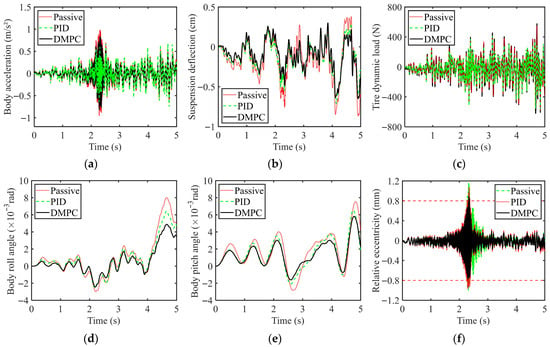
Figure 15.
Comparison of simulation results under uniform accelerated conditions: (a) Body acceleration; (b) Suspension deflection; (c) Tire dynamic load; (d) Body roll angle; (e) Body pitch angle; (f) Relative eccentricity.

Table 1.
Comparison of performance indicators in uniform acceleration phase.
Figure 16 shows the dynamic comparative simulation results under constant speed conditions, and the values of each performance index are presented in Table 2. It can be observed that the system’s response amplitude under this condition exhibits a slight increase compared to the uniform acceleration condition. During this operating phase, the vehicle dynamics under DMPC show comprehensive improvement. Specifically, the RMS values of the vehicle body vibration acceleration and relative eccentricity are reduced by 11.11% and 5.04%, respectively, compared to the passive suspension. Particularly noteworthy is that DMPC improves the body pitch angle and roll angle by 27.78% and 35.19%, respectively—approximately 10% greater improvement than achieved with PID control. As a result, ride comfort, body attitude stability, and motor operational performance are all enhanced. Furthermore, both the suspension deflection and tire dynamic load are not only kept within constraint boundaries but are also optimized by 23.3% and 2.6%, respectively, relative to the passive suspension.
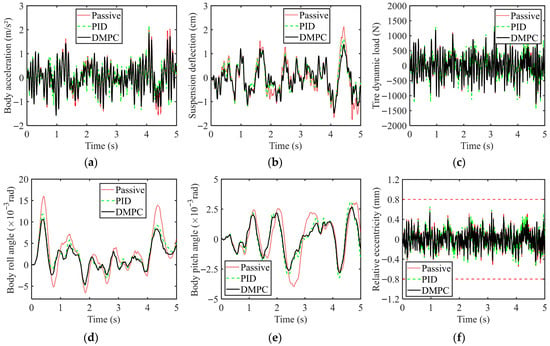
Figure 16.
Comparison of simulation results under constant speed condition: (a) Body acceleration; (b) Suspension deflection; (c) Tire dynamic load; (d) Body roll angle; (e) Body pitch angle; (f) Relative eccentricity.

Table 2.
Comparison of performance indicators in constant speed phase.
In summary, compared to PID control, the DMPC controller designed in this study demonstrates comprehensive advantages. It significantly reduces body vibration acceleration, pitch angle, and roll angle, thereby improving ride comfort and posture stability. Moreover, it more effectively suppresses the growth of relative eccentricity and reduces the occurrences of relative eccentricity exceeding the air gap boundary, leading to enhanced motor operational performance—an achievement not realized with PID control.
6. Conclusions
In order to explore the influence of UEF of the IWM on vehicle dynamic performance, this paper constructs an EMC system model for IWM-driven EVs, and analyzes the longitudinal, lateral, and vertical dynamic negative effects caused by IWM-UEF under constant speed, uniform acceleration, uniform deceleration, and uniform high-speed steering conditions. Finally, the accuracy of the established model is verified by real-vehicle tests. Based on this study, the following conclusions can be drawn:
- (1)
- This paper constructs an EMC system model for IWM-driven EVs, which includes a PMSM-UEF model, an IWM-drive model, and a vehicle dynamic system model. This model can accurately capture the dynamic coupling relationship between driving conditions, electromagnetic excitation, and vehicle vibration, laying a theoretical foundation for subsequent exploration of the influence mechanism of UEF on vehicle dynamic performance.
- (2)
- The influence mechanism of the IWM-UEF under multiple operating conditions can be summarized as follows: during constant-speed driving, it aggravates the motor’s relative eccentricity, threatening IWM stability; under uniform acceleration/deceleration conditions, it causes a significant increase in body vibration acceleration and motor relative eccentricity within the low-speed range of 0–5 m/s, resulting in substantial deterioration of both ride comfort and IWM operational stability; and under uniform high-speed steering conditions, the influence of UEF on vertical dynamic performance is manifested only as localized and transient deterioration of body vertical vibration, while the lateral dynamic performance parameters are less affected due to stable tire dynamic loads.
- (3)
- The DMPC method proposed in this paper effectively improves the comprehensive performance of IWM-driven EVs under different driving conditions. It significantly reduces body vibration acceleration, body pitch angle, and roll angle, thereby improving vehicle ride comfort and body posture stability. Furthermore, it effectively suppresses the growth of relative eccentricity, reduces the instances where relative eccentricity exceeds the air gap boundary, and consequently enhances IWM operational performance.
This study primarily focuses on the impact of UEF in IWM on vehicle dynamic performance; however, several limitations remain. First, the established analytical model of UEF is based on static eccentricity and does not fully account for the more common and complex dynamic or oblique eccentricity that occurs during actual vehicle operation. Furthermore, the suppression of negative vibration effects is achieved through active suspension control, rather than addressing the root cause of UEF generation from the perspective of in-wheel motor control. Future work should further investigate the influence of UEF under dynamic eccentricity or oblique eccentricity conditions on vehicle dynamics and explore strategies to reduce UEF through improved IWM control.
Author Contributions
Conceptualization, X.M. and Y.R.; methodology, Y.R.; software, Y.R.; validation, Y.R. and D.S.; formal analysis, Y.R.; data curation, Y.R. and D.S.; writing—original draft preparation, Y.R.; writing—review and editing, X.M., R.D. and W.L.; supervision, R.D. and R.W.; project administration, R.W.; funding acquisition, R.W. All authors have read and agreed to the published version of the manuscript.
Funding
This research was supported by the National Key Research and Development Program of China (2023YFB2504500), the National Natural Science Foundation Project of China (52472410), and the Project of College of Agricultural Engineering, Jiangsu University (NZXB20210101).
Data Availability Statement
The original contributions presented in this study are included in the article. Further inquiries can be directed to the corresponding author(s).
Conflicts of Interest
The authors declare no conflicts of interest.
Appendix A

Table A1.
Structural parameters of PMSM.
Table A1.
Structural parameters of PMSM.
| Parameter | Symbol | Value | Unit |
|---|---|---|---|
| Slot number | 51 | — | |
| Pole number | 23 | — | |
| Radius of the stator surface | 0.1 | m | |
| Radius of the stator surface | 0.1033 | m | |
| Relative recoil permeability | 1.1 | — | |
| Magnet remanence | 1.044 | T | |
| Number of parallel branches | 1 | — | |
| Magnet arc to pole pitch ratio | 1 | — | |
| Unit motor winding pitch | — | ||
| Number of turns slot winding | 8 | — | |
| Slot width | 0.00214 | m | |
| Slot angle | rad | ||
| Management racial thickness | 0.0025 | m | |
| Axial length of the motor | 0.06 | m | |
| Air gap length | 0.0008 | m |

Table A2.
Nominal parameters of PMSM.
Table A2.
Nominal parameters of PMSM.
| Parameter | Value | Unit |
|---|---|---|
| Rated power | 4 | kw |
| Rated voltage | 72 | V |
| Stator equivalent resistance | 0.3 | Ω |
| Three-phase winding self-inductance | 2.9 × 10⁻⁵ | H |
| Rotor moment of inertia | 0.02 | kg·m2 |

Table A3.
18-DOF vehicle model parameters.
Table A3.
18-DOF vehicle model parameters.
| Parameter | Symbol | Value | Unit |
|---|---|---|---|
| Sprung mass | 720 | kg | |
| The mass of the motor rotor | 17 | kg | |
| The mass of the motor stator | 22.5 | kg | |
| Body roll moment of inertia | 319 | kg·m2 | |
| Body pitch moment of inertia | 1192 | kg·m2 | |
| Vehicle yaw moment of inertia | 1000 | kg·m2 | |
| Stiffness of front suspension spring | 15 | kN/m | |
| Stiffness of rear suspension spring | 17 | kN/m | |
| Motor bearing stiffness | 4000 | kN/m | |
| Tire stiffness | 200 | kN/m | |
| Damp of front suspension spring | 1 | kN·s/m | |
| Damp of rear suspension spring | 1 | kN·s/m | |
| Wheel track width | 1.33 | m | |
| Distance from centroid to front axle | 0.795 | m | |
| Distance from centroid to rear axle | 0.975 | m | |
| Distance from centroid to pitch axis | 0.105 | m | |
| Distance from centroid to roll axis | 0.235 | m | |
| Distance from centroid to ground | 0.495 | m |
Appendix B
Part of the matrix in the state space equation described by Equation (29) (In order to simplify the operation, the front wheelbase A and the rear wheelbase B are written as T because they are equal):
References
- Tu, R.; Gai, Y.; Farooq, B.; Posen, D.; Hatzopoulou, M. Electric vehicle charging optimization to minimize marginal greenhouse gas emissions from power generation. Appl. Energy 2020, 277, 115517. [Google Scholar] [CrossRef]
- Zhu, Z.; Zeng, L.; Chen, L.; Zou, R.; Cai, Y. Fuzzy Adaptive Energy Management Strategy for a Hybrid Agricultural Tractor Equipped with HMCVT. Agriculture 2022, 12, 1986. [Google Scholar] [CrossRef]
- He, S.; Fan, X.; Wang, Q.; Chen, X.; Zhu, S. Review on Torque Distribution Scheme of Four-Wheel In-Wheel Motor Electric Vehicle. Machines 2022, 10, 619. [Google Scholar] [CrossRef]
- Liu, H.; Yan, S.; Shen, Y.; Li, C.; Zhang, Y.; Hussain, F. Model predictive control system based on direct yaw moment control for 4WID self-steering agriculture vehicle. Int. J. Agric. Biol. Eng. 2021, 14, 175–181. [Google Scholar] [CrossRef]
- Deepak, K.; Frikha, M.A.; Benomar, Y.; El Baghdadi, M.; Hegazy, O. In-Wheel Motor Drive Systems for Electric Vehicles: State of the Art, Challenges, and Future Trends. Energies 2023, 16, 3121. [Google Scholar] [CrossRef]
- Zhu, H.; Zhang, F.; Zhang, Y.; Su, L.; Gong, G. Yaw Stability Research of the Distributed Drive Electric Bus by Adaptive Nonsingular Fast Terminal Sliding Mode Control. Machines 2022, 10, 969. [Google Scholar] [CrossRef]
- Yuexia, C.; Long, C.; Ruochen, W.; Xing, X.; Yujie, S.; Yanling, L. Modeling and test on height adjustment system of electrically-controlled air suspension for agricultural vehicles. Int. J. Agric. Biol. Eng. 2016, 9, 40–47. [Google Scholar] [CrossRef]
- Zhao, Z.; Taghavifar, H.; Du, H.; Qin, Y.; Dong, M.; Gu, L. In-Wheel Motor Vibration Control for Distributed-Driven Electric Vehicles: A Review. IEEE Trans. Transp. Electrif. 2021, 7, 2864–2880. [Google Scholar] [CrossRef]
- Zhao, Z.; Zhang, L.; Wu, J.; Gu, L.; Li, S. Vertical-Longitudinal Coupling Effect Investigation and System Optimization for a Suspension-In-Wheel-Motor System in Electric Vehicle Applications. Sustainability 2023, 15, 4168. [Google Scholar] [CrossRef]
- Shao, X.; Naghdy, F.; Du, H.; Qin, Y. Coupling effect between road excitation and an in-wheel switched reluctance motor on vehicle ride comfort and active suspension control. J. Sound Vib. 2019, 443, 683–702. [Google Scholar] [CrossRef]
- Li, Z.; Zheng, L.; Ren, Y.; Li, Y.; Xiong, Z. Multi-objective optimization of active suspension system in electric vehicle with In-Wheel-Motor against the negative electromechanical coupling effects. Mech. Syst. Signal Process. 2019, 116, 545–565. [Google Scholar] [CrossRef]
- Qin, Y.; He, C.; Shao, X.; Du, H.; Xiang, C.; Dong, M. Vibration mitigation for in-wheel switched reluctance motor driven electric vehicle with dynamic vibration absorbing structures. J. Sound Vib. 2018, 419, 249–267. [Google Scholar] [CrossRef]
- Wu, H.; Zheng, L.; Li, Y. Coupling effects in hub motor and optimization for active suspension system to improve the vehicle and the motor performance. J. Sound Vib. 2020, 482, 115426. [Google Scholar] [CrossRef]
- Wu, H.; Zheng, L.; Li, Y.; Zhang, Z.; Yu, Y. Robust Control for Active Suspension of Hub-Driven Electric Vehicles Subject to in-Wheel Motor Magnetic Force Oscillation. Appl. Sci. 2020, 10, 3929. [Google Scholar] [CrossRef]
- Li, Z.; Song, X.; Chen, X.; Xue, H. Dynamic Characteristics Analysis of the Hub Direct Drive-Air Suspension System from Vertical and Longitudinal Directions. Shock Vib. 2021, 2021, 8891860. [Google Scholar] [CrossRef]
- Hu, Y.; Li, Y.; Li, Z.; Zheng, L. Analysis and suppression of in-wheel motor electromagnetic excitation of IWM-EV. Proc. Inst. Mech. Eng. Part D-J. Automob. Eng. 2021, 235, 1552–1572. [Google Scholar] [CrossRef]
- Li, Q.; Ma, C.; Zhang, N.; Guo, Y.; Degano, M.; Gerada, C.; Zhou, S.; An, Y. Analysis of longitudinal-vertical coupling vibration of four hub motors driven electric vehicle under unsteady condition. Proc. Inst. Mech. Eng. Part D-J. Automob. Eng. 2025, 239, 2106–2117. [Google Scholar] [CrossRef]
- Wang, Y.-y.; Li, Y.-n.; Sun, W.; Zheng, L. Effect of the unbalanced vertical force of a switched reluctance motor on the stability and the comfort of an in-wheel motor electric vehicle. Proc. Inst. Mech. Eng. Part D-J. Automob. Eng. 2015, 229, 1569–1584. [Google Scholar] [CrossRef]
- Tan, D.; Lu, C. The Influence of the Magnetic Force Generated by the In-Wheel Motor on the Vertical and Lateral Coupling Dynamics of Electric Vehicles. Ieee Trans. Veh. Technol. 2016, 65, 4655–4668. [Google Scholar] [CrossRef]
- Li, X.; Deng, Z.; Chen, T.; Zhang, Y.; Wei, H. Negative dynamics effect of in-wheel switched reluctance motor with inclined airgap eccentricity on handing stability for electric vehicle. Proc. Inst. Mech. Eng. Part D-J. Automob. Eng. 2024, 238, 3707–3720. [Google Scholar] [CrossRef]
- Wu, H.; Jiang, Y.; Guo, D.; Huang, J.; Huang, Q. Robust Preview Control for Half-Vehicle Active Suspension System of Hub-Driven Electric Vehicles with Coupling Effects. Shock Vib. 2024, 2024, 9904307. [Google Scholar] [CrossRef]
- Yu, Y.; Li, Z.; Zhou, Y.; Wang, X. A nonlinear model predictive control for air suspension in hub motor electric vehicle. Proc. Inst. Mech. Eng. Part D-J. Automob. Eng. 2025, 239, 564–585. [Google Scholar] [CrossRef]
- Zhang, Y.; Wang, D.; Yin, Y.; Peng, Z. Event-triggered distributed coordinated control of networked autonomous surface vehicles subject to fully unknown kinetics via concurrent-learning-based neural predictor. Ocean Eng. 2021, 234, 108966. [Google Scholar] [CrossRef]
- Liang, J.; Lu, Y.; Pi, D.; Yin, G.; Zhuang, W.; Wang, F.; Feng, J.; Zhou, C. A Decentralized Cooperative Control Framework for Active Steering and Active Suspension: Multi-Agent Approach. Ieee Trans. Transp. Electrif. 2022, 8, 1414–1429. [Google Scholar] [CrossRef]
- Zhang, N.; Yang, S.; Wu, G.; Ding, H.; Zhang, Z.; Guo, K. Fast Distributed Model Predictive Control Method for Active Suspension Systems. Sensors 2023, 23, 3357. [Google Scholar] [CrossRef]
- Ma, C.; Chen, C.; Li, Q.; Gao, H.; Kang, Q.; Fang, J.; Cui, H.; Teng, K.; Lv, X. Analytical Calculation of No-Load Magnetic Field of External Rotor Permanent Magnet Brushless Direct Current Motor Used as In-Wheel Motor of Electric Vehicle. IEEE Trans. Magn. 2018, 54, 1–6. [Google Scholar] [CrossRef]
- Ma, C.; Cui, H.; Zheng, P.; Zhang, Y.; Gao, H. Influence of static eccentricity on unbalanced magnetic force of external rotor permanent magnet brushless direct current motor used as In-wheel motor. IET Electr. Power Appl. 2019, 13, 538–550. [Google Scholar] [CrossRef]
- Ma, C.; Li, Q.; Lu, H.; Liu, Y.; Gao, H. Analytical model for armature reaction of outer rotor brushless permanent magnet DC motor. IET Electr. Power Appl. 2018, 12, 651–657. [Google Scholar] [CrossRef]
- Ma, C.; Li, Q.; Zheng, P.; Zhou, S.; Gao, H.; Fang, J.; Wang, Y. Effects of static eccentricity on the no-load back electromotive force of external rotor permanent magnet brushless DC motor used as in-wheel motor. IET Electr. Power Appl. 2019, 13, 604–613. [Google Scholar] [CrossRef]
- Zarko, D.; Ban, D.; Lipo, T. Analytical calculation of magnetic field distribution in the slotted air gap of a surface permanent-magnet motor using complex relative air-gap permeance. IEEE Trans. Magn. 2006, 42, 1828–1837. [Google Scholar] [CrossRef]
- Yu, Y.; Hao, S.; Guo, S.; Tang, Z.; Chen, S. Motor Torque Distribution Strategy for Different Tillage Modes of Agricultural Electric Tractors. Agriculture 2022, 12, 1373. [Google Scholar] [CrossRef]
- Turker, T.; Buyukkeles, U.; Bakan, A.F. A Robust Predictive Current Controller for PMSM Drives. IEEE Trans. Ind. Electron. 2016, 63, 3906–3914. [Google Scholar] [CrossRef]
- Qixun, Z.; Ziwei, C.; Pei, W.; Yufeng, Z. Dead-beat Optimization Model Predictive Control of Dual Three-phase Permanent Magnet Synchronous Motor. Power Electron. 2022, 56, 20–23. [Google Scholar]
- Yu, F.; Li, K.; Zhu, Z.; Liu, X. An Over-Modulated Model Predictive Current Control for Permanent Magnet Synchronous Motors. Ieee Access 2022, 10, 40391–40401. [Google Scholar] [CrossRef]
- Zheng, X.; Gao, X.; Zhao, Z. Simulation analysis of tire dynamic based on “Magic Formula”. Mach. Electron 2012, 9, 16–20. [Google Scholar]
- Chen, Y.; Chen, L.; Huang, C.; Lu, Y.; Wang, C. A dynamic tire model based on HPSO-SVM. Int. J. Agric. Biol. Eng. 2019, 12, 36–41. [Google Scholar] [CrossRef]
Disclaimer/Publisher’s Note: The statements, opinions and data contained in all publications are solely those of the individual author(s) and contributor(s) and not of MDPI and/or the editor(s). MDPI and/or the editor(s) disclaim responsibility for any injury to people or property resulting from any ideas, methods, instructions or products referred to in the content. |
© 2025 by the authors. Licensee MDPI, Basel, Switzerland. This article is an open access article distributed under the terms and conditions of the Creative Commons Attribution (CC BY) license (https://creativecommons.org/licenses/by/4.0/).