
Experimental Study on Permeation of Composite Grout with Multi-Particle-Size Distribution: Comparative Analysis with Nano-Silica Sol and Cement Grout


Abstract
1. Introduction
2. Experimental Design
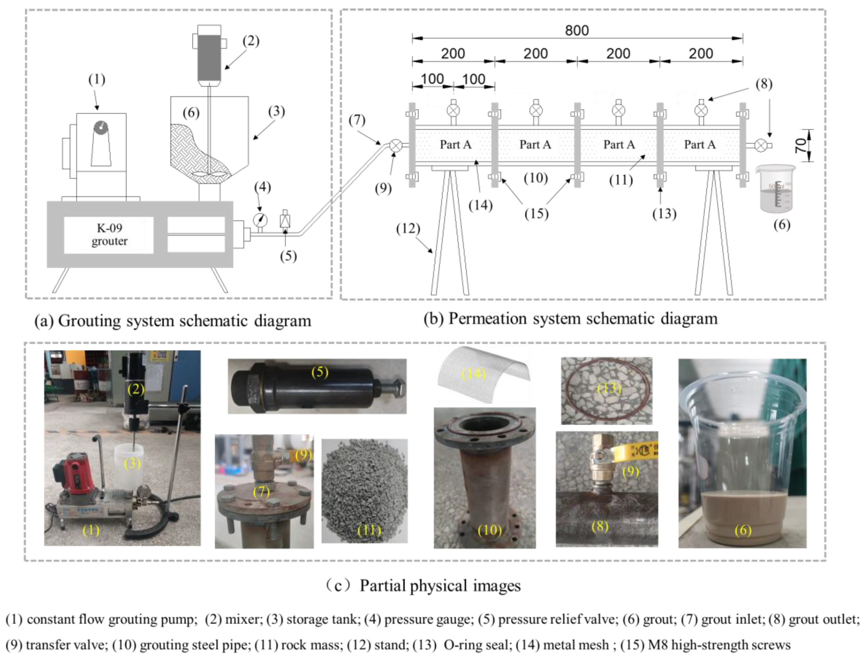
2.1. Experimental Equipment
- (1)
- Grouting Experimental System
- (2)
- Grouting Seepage System
- (3)
- Measurement System
2.2. Experimental Materials
- (1)
- Rock Materials
- (2)
- Grouting Materials
2.3. Experimental Steps
- (1)
- The grouting end was connected to the steel tube, and single-way valves were installed on each segment. The inner walls of each steel tube were coated with a layer of Vaseline, followed by a thin plastic film that was also coated with Vaseline to ensure a smooth surface and prevent leakage. M8 high-strength screws were used to connect the four segmented grouting tubes. Rock fragments were evenly filled into the grouting tubes from a fixed height in layers and compacted thoroughly; then, the discharge end cap was installed, and the permeation apparatus was placed on a stand.
- (2)
- The high-pressure grouting pipe was connected to a constant-flow grouting pump, a pressure-relief valve, a grout storage barrel, and the grouting permeation system. The specifically proportioned grout material (silica gel, cement grout, composite grout) was poured into the storage barrel, and the grout was continuously stirred using a mixer. The grouting pump’s flow rate was set to 800 mL/min, and the grouting pipe valve along with the grouting pump were opened to start the permeation grouting experiment. Once the grout began flowing out steadily from the discharge end, the grouting pump was stopped every 10 s (at permeation times of 10 s, 20 s, 30 s, 40 s, and 50 s), and the single-way valves on each steel tube were opened to collect the grout flowing out at different depths (100 mm, 300 mm, 500 mm, and 700 mm).
- (3)
- The grouting was stopped when the total grout volume reached 3 L, the grouting time reached 1 min, or when the pressure gauge indicated an over-limit value and a significant amount of grout leaked through the pressure-relief valve. After each grouting experiment, the grouting pipelines were cleaned with water.
- (4)
- After each grouting operation, the electrical conductivity and the stone-formation rate of the outflowing grout were measured. Additionally, the setting time for some of the samples was measured.
- (5)
- After the grouting process had completed and 24 h had elapsed, the permeation experiment apparatus was disassembled section by section, and the grouted material cemented rock composites (hereafter referred to as grout–rock cemented bodies) were placed in a curing chamber with constant temperature and humidity. The samples were maintained in a standard curing environment of 20 °C temperature and >95% relative humidity for 7 days. Afterwards, each section was cut into two pieces and subjected to uniaxial compressive strength tests. Each section was tested twice to obtain the average value, which was used as the compressive strength for that section.
- (6)
- Following the above procedures, the permeation and consolidation patterns of three different grout materials (silica gel, cement grout, and composite grout) were tested within three ranges of rock fragment sizes (0.5–2 mm, 2–5 mm, and 5–10 mm).
3. Experimental Results
3.1. Flow and Permeation Characteristics of Silica-Gel Grouting
- (1)
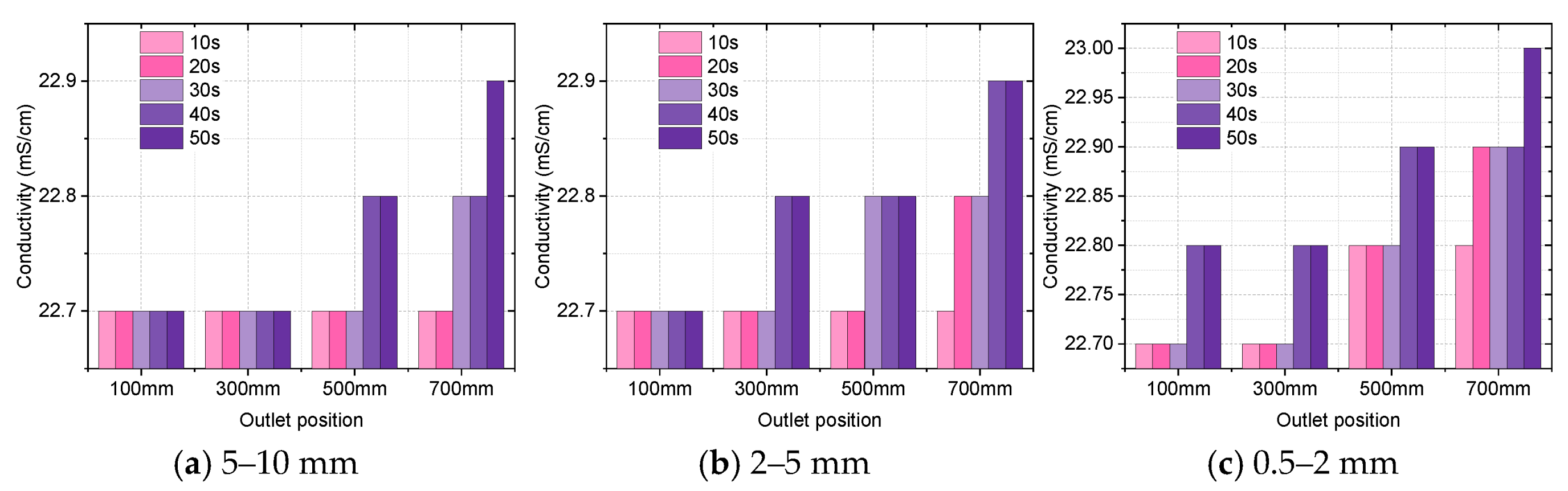
- Change in Electrical Conductivity
- (2)
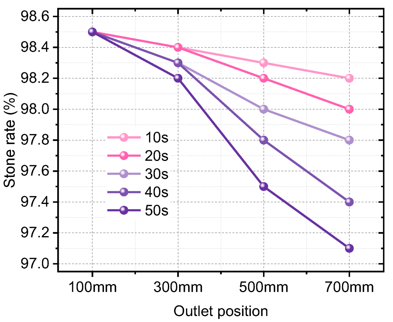
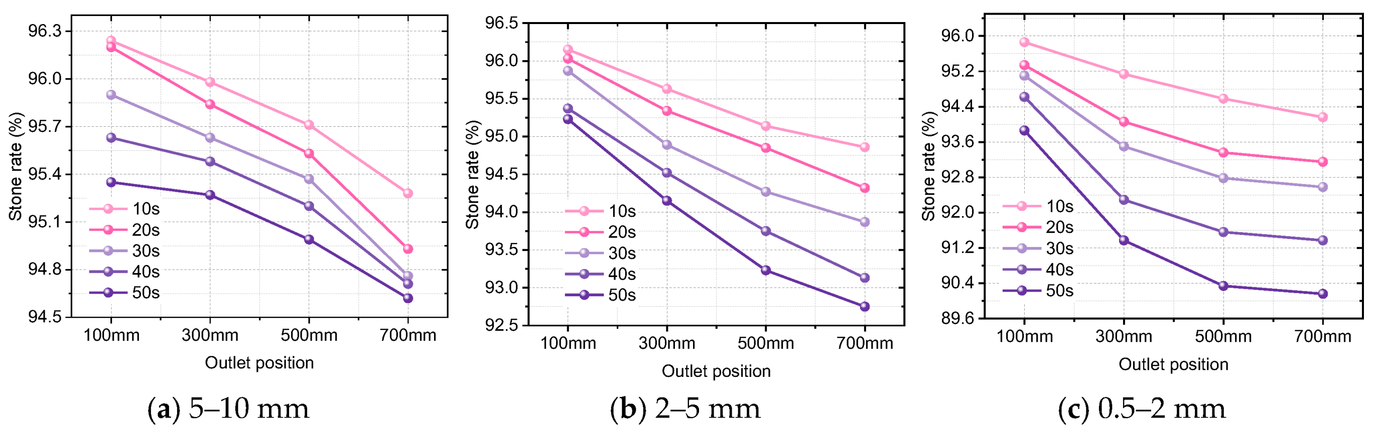
- Change in Stone-Formation Rate
3.2. Flow and Permeation Characteristics of Cement Grout
- (1)
- Change in Electrical Conductivity
- (2)
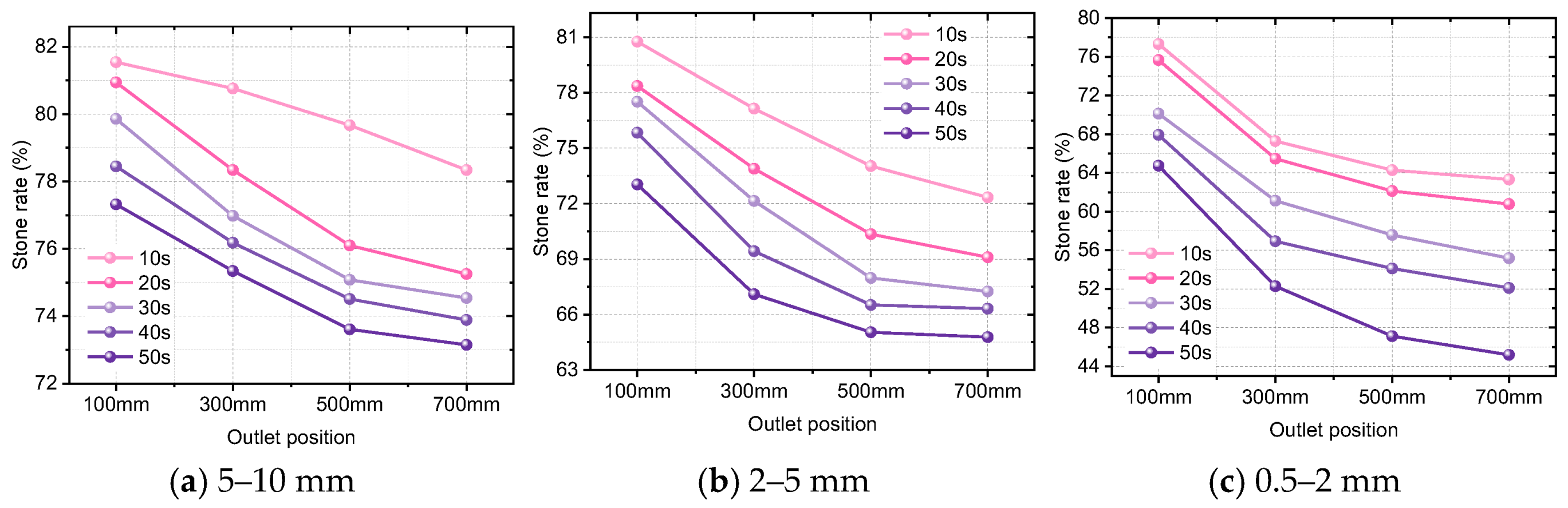
- Change in Stone-Formation Rate
3.3. Flow and Permeation Characteristics of Modified Composite-Grout Materials
- (1)
- Change in Electrical Conductivity
- (2)
- Change in Stone-Formation Rate
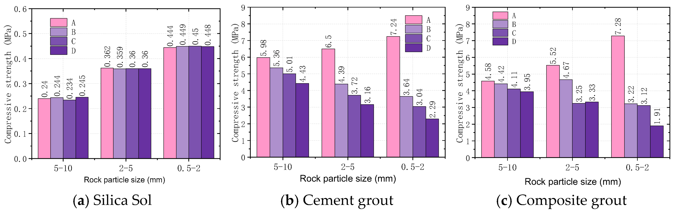
3.4. Effects of Three Grout Materials on Reinforcement of Argillaceous Fractured Rock Bodies
4. Discussion
4.1. Adaptability and Comparison of Composite Grout to Rock Body Permeation Characteristics
4.2. Grouting Technology and Application Prospects
5. Conclusions
- (1)
- Conductivity can be achieved through ion transport in a granular gel system, and the percolation characteristics of slurry can be reflected through the conductivity and stone rate of percolation slurry. Silica sol is a grouting material with nanometer particles. Under the condition that the fracture level remains unchanged, the seepage depth and time have little influence on the slurry flow and particle loss, and the stone rate and gel strength are weakly affected by the rock mass seepage.
- (2)
- Cement grout is significantly affected by rock permeation. With the increase in infiltration depth and infiltration time, the sedimentation amount of large particles in the cement slurry filtered by the rock skeleton increases, and the pore blockage becomes larger. As the degree of rock fragmentation decreases, the extent of superficial permeation increases, leading to a notable reduction in the deep-rock stone-formation rate and compressive strength. The minimum stone-formation rate is reduced to 45.19%, and the minimum compressive strength is reduced to 2.29 MPa, substantially diminishing the sealing and reinforcement effects of cement grouting on deep rock bodies.
- (3)
- The impact of rock permeation on composite grout with nano–micro and multi-particle-size distribution primarily affects the compressive strength of the formed stones, while the stability and stone-formation rate of the grout are less influenced. With decreasing permeability, the location of rock permeation moves closer to the rock surface, and the sealing of deeper rock bodies is less affected. Therefore, the composite grout can not only achieve shallow reinforcement but also realizes deep sealing.
- (4)
- Composite-grout material can be easily used with conventional single-fluid grouting pumps and requires only the basic mixing and stirring of the materials. In areas with small-aperture fracture development, such as deep micro-cracks, the grout can be mixed and used independently. In scenarios with multi-scale fracture development, such as deep fractured rock-mass tunnels, it is necessary to use the composite grout in conjunction with aluminate cement for combined deep and shallow grouting.
- (5)
- Future research recommendations: The interaction mechanism between the gelation of silica-sol composite slurry and mudstone mudification in water-rich environments still needs to be revealed. There is still potential for optimizing the grouting performance of composite-grout materials. The industrial testing and promotion of silica-sol slurry materials still need strengthening.
Author Contributions
Funding
Data Availability Statement
Conflicts of Interest
References
- Koralegedara, N.; Maynard, J. Chemical, mineralogical and textural properties of the kope formation mudstones: How they affect its durability. Eng. Geol. 2017, 228, 312–322. [Google Scholar] [CrossRef]
- Zhao, Y.; Ren, S.; Jiang, D.; Liu, R.; Wu, J.; Jiang, X. Influence of wetting-drying cycles on the pore structure and mechanical properties of mudstone from simian mountain. Constr. Build. Mater. 2018, 191, 923–931. [Google Scholar] [CrossRef]
- Jiang, Q.; Cui, J.; Feng, X.; Jiang, Y. Application of computerized tomographic scanning to the study of water-induced weakening of mudstone. Bull. Eng. Geol. Environ. 2014, 73, 1293–1301. [Google Scholar] [CrossRef]
- Liu, J.; Xu, Q.; Wang, S.; Subramanian, S.; Wang, L.; Qi, X. Formation and chemo-mechanical characteristics of weak clay interlayers between alternative mudstone and sandstone sequence of gently inclined landslides in Nanjiang, SW China. Bull. Eng. Geol. Environ. 2014, 79, 4701–4715. [Google Scholar] [CrossRef]
- Ma, H.; Liu, Q. Prediction of the peak shear strength of sandstone and mudstone joints infilled with high water–cement ratio grouts. Rock Mech. Rock Eng. 2017, 50, 2021–2037. [Google Scholar] [CrossRef]
- Sogaard, C.; Funehag, J.; Abbas, Z. Silica sol as grouting material: A physio-chemical analysis. Nano Converg. 2018, 5, 6. [Google Scholar] [CrossRef] [PubMed]
- Sandbak, L.; Rai, A. Ground support strategies at the turquoise ridge joint venture, Nevada. Rock Mech. Rock Eng. 2013, 46, 437–454. [Google Scholar] [CrossRef]
- Pan, D.; Hong, K.; Fu, H.; Zhou, J.; Zhang, N.; Lu, G. Influence characteristics and mechanism of fragmental size of broken coal mass on the injection regularity of silica sol grouting. Constr. Build. Mater. 2021, 269, 121251. [Google Scholar] [CrossRef]
- Huang, Z.; Chen, M.; Chen, X. A developed technology for wet-ground fine cement slurry with its applications. Cem. Concr. Res. 2003, 33, 729–732. [Google Scholar] [CrossRef]
- Chen, J.; Kwan, A. Superfine cement for improving packing density, rheology and strength of cement paste. Cem. Concr. Comp. 2012, 34, 1–10. [Google Scholar] [CrossRef]
- Yao, W.; Pang, J.; Liu, Y. An experimental study of Portland cement and superfine cement slurry grouting in loose sand and sandy soil. Infrastructures 2018, 2, 9. [Google Scholar] [CrossRef]
- Ghafar, A.N.; Mentesidis, A.; Draganovic, A.; Larsson, S. An experimental approach to the development of dynamic pressure to improve grout spread. Rock Mech. Rock Eng. 2016, 49, 3709–3721. [Google Scholar] [CrossRef]
- El Tani, M.; Stille, H. Grout spread and injection period of silica solution and cement mix in rock fractures. Rock Mech. Rock Eng. 2017, 50, 2365–2380. [Google Scholar] [CrossRef]
- Han, W.W. Mechanism and Engineering Application of Porous Medium Grouting of Cement Slurry Based on Infiltration Effect. Doctoral Dissertation, Shandong University, Jinan, China, 2014. [Google Scholar]
- Yu, Y.Q.; Zhang, J.Y.; Fan, D.L.; Wang, S.; Xu, F.; Yang, J.; Ren, L. Development of grouting test device and diffusion law of grout in fractured rock mass under high temperature and rich water environment. J. China Coal Soc. 2022, 47, 2582–2592. [Google Scholar]
- Wang, K. Research on the Seepage Characteristics and Application of High-Pressure Grouting in Soft Rock with Micro Cracks in Deep Wells. Master’s Thesis, China University of Mining and Technology, Xuzhou, China, 2020. [Google Scholar]
- Al-Zu’bi, M.; Fan, M.; Al Rjoub, Y.; Ashteyat, A.; Al-Kheetan, M.J.; Anguilano, L. The effect of length and inclination of carbon fiberreinforced polymer laminates on shear capacity ofnear-surface mounted retrofitted reinforced concrete beams. Struct. Concr. 2021, 22, 3677–3691. [Google Scholar] [CrossRef]
- Pan, D.; Zhang, N.; Xiang, Z.; Xie, Z. Performance improvement of nanocolloidal silica-aluminate cement composite grouting materials with organic acids. Case Stud. Constr. Mater. 2024, 20, e03166. [Google Scholar] [CrossRef]
- Xiang, Z.; Zhang, N.; Pan, D.; Xie, Z.; Zhao, Y. Development and performance characterization of a composite grouting material suitable for sealing and reinforcement of microcracked mudstone. J. Mater. Res. Technol. 2023, 26, 3726–3743. [Google Scholar] [CrossRef]
- Liu, N.K.; Pan, D.J.; Wen, S.Y.; Liu, H.; Zhou, J.; Li, Z. Design and Performance Optimization Analysis of Nano silica Sol Aluminate Cement Composite Slurry for Mud Soft Rock Tunnel. Tunnel Constr. 2022, 42, 303–312. [Google Scholar]
- Xiang, Z.; Zhang, N.; Pan, D.J.; Xie, Z.Z. Basic consolidation and impermeability laws for nano-silica-sol grouted mudstone. Constr. Build. Mater. 2023, 403, 133121. [Google Scholar] [CrossRef]
- Hodne, H.; Saasen, A. The effect of the cement zeta potential and slurry conductivity on the consistency of oilwell cement slurries. Cem. Concr. Res. 2000, 30, 1767–1772. [Google Scholar] [CrossRef]
- Chai, Z.Y.; Liu, X.; Yang, P.; Guo, R.; Yang, Z. Experimental study on the physical properties of silica sol and its grouting modified mudstone. J. Rock Mech. Eng. 2021, 40, 2681–2691. [Google Scholar]


| Appearance | pH | Density/(g/m3) | Viscosity/mPa·s | Average Particle Size/nm | SiO2 Concentration/% | Na2O Concentration/% |
|---|---|---|---|---|---|---|
| Light blue, transparent | 9.55 | 1.203 | ≤5 | 9.6 | 30.18 | 0.31 |
| CaO | SiO2 | Al2O3 | Fe2O3 | MgO | SO3 | R2O | Others |
|---|---|---|---|---|---|---|---|
| 64.02 | 20.94 | 4.85 | 3.44 | 1.7 | 1.88 | 0.50 | 2.67 |
| SiO2 | CaO | Al2O3 | Fe2O3 | SO3 | K2O | Na2O | LOI |
|---|---|---|---|---|---|---|---|
| 5.01 | 36.1 | 52.24 | 1.71 | 0.61 | 0.2 | 0.25 | 0.21 |
Disclaimer/Publisher’s Note: The statements, opinions and data contained in all publications are solely those of the individual author(s) and contributor(s) and not of MDPI and/or the editor(s). MDPI and/or the editor(s) disclaim responsibility for any injury to people or property resulting from any ideas, methods, instructions or products referred to in the content. |
© 2025 by the authors. Licensee MDPI, Basel, Switzerland. This article is an open access article distributed under the terms and conditions of the Creative Commons Attribution (CC BY) license (https://creativecommons.org/licenses/by/4.0/).
Share and Cite
Xiang, Z.; Zhang, N.; Xie, Z.; Tang, H.; Song, Z. Experimental Study on Permeation of Composite Grout with Multi-Particle-Size Distribution: Comparative Analysis with Nano-Silica Sol and Cement Grout. Processes 2025, 13, 172. https://doi.org/10.3390/pr13010172
Xiang Z, Zhang N, Xie Z, Tang H, Song Z. Experimental Study on Permeation of Composite Grout with Multi-Particle-Size Distribution: Comparative Analysis with Nano-Silica Sol and Cement Grout. Processes. 2025; 13(1):172. https://doi.org/10.3390/pr13010172
Chicago/Turabian StyleXiang, Zhe, Nong Zhang, Zhengzheng Xie, Huajun Tang, and Ziheng Song. 2025. "Experimental Study on Permeation of Composite Grout with Multi-Particle-Size Distribution: Comparative Analysis with Nano-Silica Sol and Cement Grout" Processes 13, no. 1: 172. https://doi.org/10.3390/pr13010172
APA StyleXiang, Z., Zhang, N., Xie, Z., Tang, H., & Song, Z. (2025). Experimental Study on Permeation of Composite Grout with Multi-Particle-Size Distribution: Comparative Analysis with Nano-Silica Sol and Cement Grout. Processes, 13(1), 172. https://doi.org/10.3390/pr13010172