Abstract
The rise of Industry 4.0 has introduced challenges and new production models like additive manufacturing (AM), enabling the creation of complex objects previously unattainable. However, many polymers remain underutilized due to the need for improved mechanical properties and reduced process-induced anisotropy. ME-based part construction involves successive filament deposition, akin to welding. Upon exiting the nozzle, the polymer solidifies within seconds, limiting the time and temperature available for diffusion and efficient bonding with the adjacent filament. Therefore, optimizing this welding process is essential. The primary objective of this review was to report on the equipment utilized to enhance the bonding between filaments deposited during manufacturing. While higher temperatures improve welding, most equipment cannot endure prolonged high-heat operations, limiting the use of engineering-grade polymers. Modifying polymer matrices by incorporating low-molar-mass molecules can boost welding and mechanical strength. Significant gains in mechanical properties have come from matrix modifications and new in situ welding devices. Reported devices use light (laser, UV IR), electric current, radio frequency and heat collection from the nozzle. The simplest device is a heat collector, while a double laser beam system has achieved the highest mechanical properties without matrix modification. There was an improvement in properties ranging from 20% to 200%.
1. Introduction
The Fourth Industrial Revolution, or Industry 4.0, is based on the combination of the physical and digital worlds and involves a new manufacturing paradigm []. In this context, additive manufacturing (AM) is a new method that allows the construction of parts according to a digital model by numerous successive steps of overlapping layers. It is important to note that the term ‘3D printing’ is frequently interpreted as a synonym for AM. This manufacturing method allows the construction of complex parts, which can be hollow or have different internal structures, which in traditional methods such as extrusion, injection and machining are not possible [,]. Parts can be manufactured with complex geometry without the need for molds or preforms, drastically reducing design and project execution time [].
In the context of producing small numbers of parts or single bespoke parts, AM has relevant advantages, such as eliminating the cost of molds and expanding the range of materials that can be employed [,,]. A huge variety of raw materials can be used to compose the layers of the final part [,,,,,].
Among the different AM techniques, the manufacture of objects by means of a molten mass that flows through a nozzle and solidifies into stacked filaments [,,,] is generally called fused deposition modeling (FDM) or material extrusion (ME), as defined by ASTM F2792. This technique is the most widespread due to the low cost of raw materials and equipment [,,,].
The patent covering the process was issued in 2009 [], but even more than 10 years later has not yet been fully mastered. The lack of development of the technique can be blamed on three main reasons: inadequate equipment involving mechanical engineering; inadequate software development; and difficult engineering applied to many raw materials. Changes to the entire system (machine and software) must enable the raw material to reach its best properties during processing. Therefore, a thorough understanding of the behavior of the polymer in printing is extremely important so that the need for action by the other areas involved (mechanical engineering and programming) is reduced.
Although currently there is a large variation of polymers, mainly in ME, two polymers stand out: poly (lactic acid) (PLA) and acrylonitrile butadiene styrene (ABS) [,,]. This is due to the difficulty of depositing many polymeric masses on the base for the construction of the layer, called ‘poor printability’ in the literature [,,,,,]. Such behavior is also associated with the major disadvantage of ME, since the construction of the layer takes place through the welding of many intra and interlayer lines between adjacent filaments [].
In the additive construction model, complex shapes can be obtained with hollow structures or with different structures, which is not possible in machining or injection/extrusion. Most of the devices are small, and can even be used in an office environment with a clean process, with energy savings of up to 25% and less waste generation (~90%) compared to conventional methods []. Regarding the time between design and obtaining the final product, it has been greatly optimized mainly as part of the concept of the Fourth Industrial Revolution, which integrates the physical and digital world. The equipment, mainly of the ME type producing filaments, can be purchased online at a cost that is accessible to the population. The raw material used in ME printers also has lower cost compared to other techniques and thus justifies the greater coverage of this technique for additive manufacturing [,,,].
The properties of the printed parts are influenced by the welding of the filaments between paths and adjacent layers []. In this way, compared to a part manufactured by common processing and 3D printing with the same polymer, inefficient welding will reduce the mechanical properties of the part, among other factors. According to the literature, the improvement of the solder has been most often achieved through the addition to the polymeric matrix of molecules with lower molar mass, where the diffusion of the polymeric solder is mainly modified by increasing the depth of diffusion (or depth of the solder) []. With regard to equipment, weld modification has been carried out mainly by means of laser devices, where considerable gains in mechanical strength have been obtained in situ construction.
Challenges in ME technology include low mechanical strength, lack of dimensional accuracy, low surface quality, small number of parts produced, anisotropy and long printing time []. The part is formed by a continuous and repeated system of welds, which reduces the mechanical resistance when compared to the properties of the raw material. The rapid cooling of the polymeric mass during deposition prevents the establishment of ideal time and temperature conditions for efficient welding. Furthermore, most printers are not designed to withstand prolonged printing periods at high temperatures, which leads to overheating in regions that should remain cool, resulting in extrusion channel clogging. Attempts to increase printing speed, aiming to deposit adjacent filaments at higher temperatures to enhance welding, have proven ineffective, as the liquefaction of the polymeric mass does not occur adequately at high flow rates. In this context, the implementation of devices to optimize in situ welding could mitigate these issues and improve process efficiency.
This work presents a literature review on the development of devices aimed at improving filament bonding during 3D printing. Additionally, it examines the properties of the polymer matrix and its modifications to better respond to the stimuli from the additional devices in the 3D printer.
The structure of this paper begins with a discussion on welding, focusing on the joining of two parts, particularly addressing the literature on the bonding of polymeric parts and the inherent challenges in the material extrusion (ME) process. The key characteristics of the polymer matrix are outlined, along with the modifications that can be made to achieve better results when the 3D printer is modified. Subsequently, the paper reviews the works in the literature regarding devices developed to improve the bonding between filaments, or the welding of adjacent filaments, in an in situ process. Thus, the importance of developing such devices and modifying 3D printers is highlighted, encouraging further research in this field by demonstrating the improvement in properties, even when using simple systems.
2. Welding Methods
The welding mechanism encompasses all the steps of joining the parts from the beginning to the end of the operation, and involves temperature, surface conditions and pressure during welding []. Polymeric welding involves direct contact of the part’s layers at temperatures above their melting point []. During welding, diffusion of molecules occurs at the contact interface and thus partial or complete diffusion of molecules can occur []. The mobility of the molecules near the surface must be stimulated by a heat source [].
Polymer welding techniques based on the heating method have been described in the literature in different categories of melting the polymer mass [,,,,,], and some variations in the terms may occur. Categorization of the main heating methods included bulk heating, friction heating, electrothermal heating and other thermal techniques, as shown in Table 1.

Table 1.
Main welding technique separated according to the fusion method based on the literature.
When performing welding, different methods can be applied to make the same part, and finding the best system should be the subject of careful analysis. Xiong et al. (2021) [] performed a comparison of some welding systems for a polymer composite system with carbon fabric and found differences of welding power. The direct comparison indicated that laser welding had the best results compared to other techniques.
Initially, laser welding was used only for metals, but due to the improvement of the technique, high-power solid-state laser welding has emerged in polymer applications []. Currently, welding of polymers using lasers already occurs on an industrial scale [], but the optical and physicochemical properties of the material must be studied []. Infrared welding has been performed on composite materials with carbon fabric [].
In general, polymer welding using ultrasonic waves is used with amorphous thermoplastics, except nylon []. Packaging, for example, can be produced by ultrasonic welding of thermoplastic polymers [], and can be applied in small areas [], which is important in ME. But choosing the welding mechanism requires knowing the behavior of the macromolecules involved. Tofangchi et al. (2019) [] investigated the use of ultrasonic vibration in the channel prior to ME deposition to enhance adhesion. The authors concluded that the ultrasonic waves induced relaxation in the macromolecules, leading to significant improvements in adhesion.
2.1. Mechanism for Welding Macromolecules and Depth of the Weld
Welding quality depends on temperature, pressure, welding operation time, contact area [] and chain density, which are in turn dependent on time and temperature []. But in ME, the pressure and welding time are difficult variables to control. In addition to the operating characteristics of the welding equipment, the characteristics of the materials must be understood, because the behavior of the macromolecules may require changing the polymer matrix or the printing method.
The interdiffusion coefficient is inversely proportional to the polymer’s viscosity [] and the welding time is directly proportional to the relaxation time of the polymer []. These parameters can be determined computationally to simulate the behavior of complex polymers during welding to optimize performance []. This is especially important in the welding of adjacent filaments, since the direct study is very complex. In the case of crosslinked polymers, there is an exponential increase in the welding time with the crosslinking and branching time of the polymer [], i.e., the relaxation time will be much longer compared to non-crosslinked polymers.
The mechanisms suggested as being responsible for weld quality are reptation movement and molecular relaxation, which affect the growth of the interfacial thickness of the solder [,,,,]. There should be a large degree of entanglement for better adhesion []. Figure 1 shows a representative diagram of the welding mechanism at time zero, above zero and much greater than zero, as described in the literature [,,]. The thermodynamic and kinetic parameters are important for understanding the weld formation and also the residual stress []. In the highlighted image, the reptation motion of the molecule occurs at the interface. The increase in temperature and reduction in molar mass reduce the reptation time and increase the weld thickness [], in addition to increasing the interpenetration due to the decrease in polymer viscosity [].
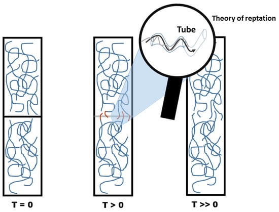
Figure 1.
Representation of molecular behavior based on the theory of molecular reptation as a function of time.
The strength of the weld will be limited by the depth of interpenetration [], i.e., the stronger the weld, the greater the penetration will be. One of the main factors affecting the depth of interdiffusion, or weld depth, is the crystallization time []. Welds can exhibit plastically deformed crystals as deep as 0.5 µm, and the depth is greater with longer interpenetration time. Also, plastic deformations can be found in the regions between the crystals []. At temperatures above the glass transition temperature (Tg), interdiffusion is observed, promoting the plastic deformation of the material due to the penetration interface [].
The factors that increase diffusion are increased contact temperature, plasticization and polymer dissolution. The factors that reduce diffusion are the presence of polar groups and crosslinks, which cause the molecules to become stiffer []. Studies indicate that the thickness of the weld was reduced in the case of long oriented chains, whose size was larger than the entanglement []. When comparing the self-strengthening as a function of temperature for low-density polyethylene (LDPE) and high-density polyethylene (HDPE), HDPE required higher temperatures for self-adhesion []. Self-adhesion is an especially important parameter in ME because for good welding there must be rheological compatibility between the filaments deposited of the same polymer mass. Indeed, this is a predominant mechanism of additive manufacturing [].
2.2. Welding in ME
The quality of welding will determine the properties of the final parts [,]; deficiency in welding leads to a decrease in interlaminar fracture toughness of the polymer matrix when compared by the conventional method []. Few in situ studies have been published due to the difficulty of analyzing very small and dynamic systems [], which increases the difficulty of finding ways to improve welding in ME []. According to Spoerk et al. (2017) [], improving the weld can increase the strength of printed parts by up to 90% over compression molded parts. Further works involving combined modification of the polymer matrix in conjunction with in situ welding are discussed below.
Mechanical evaluations of printed parts are mostly performed by tension testing, followed by flexural, Izod impact and compression testing []. Tear strength (ASTM D1938 Mode III []) has also been used to determine weld quality [,]. Such tests are used to validate the polymeric solder in printing. Scanning and optical microscopy analyses are also indicated for direct visualization of the weld and to assist qualitatively and quantitatively when the contact area of the filaments is determined [,,,,].
Welding in printing is influenced by the cooling profile [], and in conventional polymer welding, measuring this parameter in the process already presents difficulties. However, in ME, the cooling occurs much faster and total relaxation does not occur completely, so in the end there is a more anisotropic characteristic of the weld and fewer entanglements in relation to the polymeric matrix in the equilibrium in the printing conditions [].
In the process of layer construction, the top layer is deposited above the previous layer in which only a small region has sufficient temperature for welding to occur. In Figure 2, this condition is represented by the red color of higher temperatures and blue for the cooler regions. A small amount of heat is transferred to lower layers, but the second sublayer never reaches the Tg []. The region where welding occurs through interdiffusion of the molecules is immediately after the nozzle passes through the reheating of the lower layer, allowing the mobility of the molecules, as indicated by the highlight in Figure 2. The coalescence of the filaments would occur through the interdiffusion of filament molecules, as indicated by Oskolkov et al. (2023) []. Interdiffusion occurs exactly at the location immediately after the deposition of the heated polymer mass. In the solder, the temperature is not sufficient to cause annealing because the lower layers do not rise above the Tg []. Thus, a postprocessing action with annealing could increase the strength of the parts by increasing the interdiffusion.
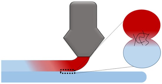
Figure 2.
Schematic representation of the welding process with emphasis on the region of interdiffusion by reheating the bottom layer.
The welding of printed parts was studied by Coasey et al. (2020) [] under endothermic conditions to analyze reptation. They found that increasing the extrusion temperature improved the curing of the 3D printed parts. This is because interdiffusion is achieved by the proper thermal properties of the deposited material []. Thus, only by mastering the technique and understanding the behavior of the polymer during the printing process will it be possible to advance regarding both equipment modification and tailoring of the polymeric matrix. This will help to enhance the properties of the printed parts as well as increasing the variety of polymers used in the technique.
2.3. Cooling Profile for Welding Filaments
The weld quality is influenced by the cooling time before the next filament is deposited and by the construction environment []. Measuring the temperature in the weld zone is a crucial step to increase weld strength []. Drastic decreases in properties can be attributed to poor interfilament diffusion as well as large increases in viscosity [].
Determining the welding time is a complex parameter, especially in the case of printed parts []. The thermal profile of the polymer mass as it solidifies forming the layers occurs in many steps and is a crucial parameter in processing. But due to spatial and temporal variations, it is difficult to carry out thermal measurements. Infrared thermographic imaging is an alternative to analyze the cooling profile in the printed part’s layers. According to a study carried out by Seppala et al. (2016) [], the heat loss happened at a rate of approximately 100 °C/s, so the temperature remained above the Tg for approximately 1 s, while time for the formation of the weld was less than 2 s.
2.4. Polymeric Matrix
2.4.1. Glass Transition (Tg)
Weld strength as a function of polymer’s molecular structure, as can be seen in Table 2, according to Pelsmaeker et al. (2018) [], where the polymers were separated into three groups: (I) those that do not weld due to the presence of aromatic fractions along the polymeric chain; (II) those with a degree of crystallinity that results in inefficient welding; and (III) amorphous polymers whose characteristic is strong welding. As indicated, the aromatic rings in the main chain of polycarbonate (PC) made welding difficult. Another determining factor was the ability to form crystalline structures, resulting in poor-quality welds. Only amorphous polymers were considered ideal for the formation of strong welds. Thus, there was no direct relationship between the Tg and the strength of the weld. Instead, this depended on the structural characteristics of the macromolecules, mainly their crystallinity.
Table 2.
Weld strengths as a function of polymer’s molecular structure. Data reorganized and adapted from Pelsmaeker et al. (2018) [].
2.4.2. Formation of the Crystalline Structure During Manufacturing
Although crystalline polymers do not show good results in welding and also produce poor printability characteristics, such polymers are still of great importance []. These must be studied so that both the polymeric matrix and the printing equipment are optimized, favoring both the formation of crystals and the formation of the weld between the deposited filaments, since both characteristics are important. Understanding the crystallinity of parts during manufacturing is thus necessary to achieve good polymeric welding [].
The evaluation of crystallinity of polymers used for printed parts is performed by differential scanning calorimetry (DSC) and X-ray diffraction analysis (XRD), the latter being the most cited technique []. Polymers with a high crystallization rate such as isotactic polypropylene (PP) are difficult to use in ME, so polymers with lower crystallization rate such as PLA are more acceptable []. The low crystallinity characteristic of PLA allows greater molecular diffusion at the interface, explaining its wide application [].
Equipment designed to measure temperature and X-ray dispersion in situ can indicate crystalline structures in the core of the deposited filaments. These two techniques can also be used to determine the relaxation of residual stress due to heat transfer when performing the upper layer deposition, in addition to the increase in chain diffusion at the interface.
The formation of crystals inside the filament results in stiffening and helps the thermodynamic and geometric stability of the melted material []. The individual crystals on the surface aid in mechanical anchoring and increase the rigidity of the weld []. Nogales et al. (2019) [] investigated the formation of crystalline structures during the deposition of filaments using X-ray diffraction.
Mass transport occurs until crystallinity stops the process []. In other words, the reduced crystallization rate and the decrease in viscosity promote greater diffusion at the weld interface []. The formation of crystals is governed by the relative molar mass and the extent of interdiffusion, so promoting greater mobility of molecules has a positive effect on interdiffusion [].
2.4.3. Molar Mass (MM) and Polydispersion
Weld quality can be affected by molar mass and polydispersion. These factors should be considered in ME since long heat and pressure application times cannot be employed in this type of processing. In polymer science, it is known that high molar mass provides greater mechanical strength to the final material and therefore is always desirable in engineering, but the increase in molecular mass makes welding difficult []. Molecules with lower molar mass work better due to the greater ease of diffusion, especially in printed parts, in the final analysis favoring the mechanical properties of the parts.
The reduction in the molar mass results in the reduction in the storage modulus, but helps to strengthen the weld []. Low MM molecules promote both diffusion and nucleation [], promoting strong welds. Low MM molecules provide greater entanglement and consequently a drastic increase in adhesion between layers and greater isotropy []. These promote both interfacial molecular diffusion and/or co-crystallization, which physically anchor the chains across the interface in the case of the polylactic acid (PLA) in ME []. Smaller molecules fuse more quickly than larger ones and thus facilitate welding []. Fabrication by printing using PLA samples with molar mass values by weight (Mw) of 148 and 100.103 g·mol−1 were compared, and the system with lower MM presented relatively higher modulus, attributed to low diffusion [].
Polydisperse systems have been studied to obtain the combination of advantages and characteristics of molecules with high and low molar mass. A good polymer system with high molar mass added to non-crystallizable low MW molecular fractions was observed to be favorable []. Stronger welds can be achieved by reducing the absolute and relative molar mass []. The difference in average molar mass (polydispersion degree) is a factor that alters the solder since molecules with low molar mass can more easily diffuse, improving joinability []. The addition of molecules that increase plasticity can decrease the anisotropy and improve the mechanical property by facilitating the diffusion of molecules and can increase the maximum stress by up to 100% according to Levenhagen et al. (2018) []. The chain terminals were found to have greater interdiffusion than the central parts of the macromolecules, and in the oriented long chain, this effect was suppressed [].
2.4.4. Additives
Additives can increase the rigidity and nucleation of crystals in the mass of the deposited filaments by up to 40%, helping in the thermodynamic and geometric stability of the printed parts []. The inclusion of additives in the polymeric matrix can alter the welding of the filaments in the printing process, and has been one of the objects of study to improving the welding strength.
Studies indicate that the inclusion of particles can improve the welding of the deposited filaments []. The inclusion of carbon fibers in a poly(ether-ether-ketone) (PEEK) matrix improved the mechanical properties of the printed parts, as it aided in the distribution of heat during thermal treatment []. Carbon nanotubes can withstand rapid heating and result in better welding, enabling printed parts to have more isotropy and even properties equivalent to those of injected parts []. Mineral fillers can further disperse the laser and reduce laser transmission [].
In ME, changing the characteristics of the polymeric matrix, such as blending, reduces the anisotropy of the printed parts regardless of the printing parameters []. In the case of polyetherimide/polycarbonate blends, a molecular diffusion simulation was carried out with printed parts, where the authors found that each component presented its own diffusion time [].
According to Levenhagen and Dadmun (2018) [], a bimodal blend was formulated by adding a polymer with low molar mass to one with high molar mass, which improved the mechanical properties of transversely printed parts. The addition of only 3% of the low molecular weight molecules increased the maximum tension by 100%. Low molar mass molecules with 2, 3 and 4 terminals were used and produced a significant improvement in the isotropic properties, with the 3-terminal molecules presenting excellent performance due to better diffusion at the interface and between filaments.
When analyzing the MM and viscosity separately for each molecule, the one with 3 terminals had the lowest viscosity value, and molecules with 4 terminals drastically increased the viscosity of the blend, which negatively influenced the diffusion and worsened the welding [].
3. Extreme Welding Conditions: Equipment Failure
A simulation of the flow of molten polymer inside the printing nozzle carried out at a temperature of 260 °C indicated that at high flow rates, the melting temperature does not reach the interior of the core at high feed rates, as evidenced by the coloration in Figure 3A []. The graph shows the difficulty of liquefying the polymer mass at higher printing speeds. In Figure 3B, at different points in the final path of the fluid, there was a drastic drop in temperature due to the increase in flow, especially at a height of 20 mm, close to the outlet, indicating a lower outlet temperature of the polymer []. According to the scheme in Figure 3C, the nozzle can be divided between the melting zone and the cooling zone, where there is a flow of heat from the heating zone to the cooling zone []. Different insulating materials were used in an attempt to optimize the equipment for PEEK printing, but even with the change of temperature and heat flow, there was still heat transfer []. In this way, although higher temperature improves welding, the equipment does not support high temperatures and longer working times. This is especially bad for engineering polymers because of the high temperatures required for processing them, particularly for ME.
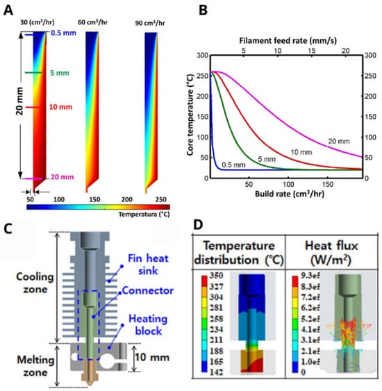
Figure 3.
Representation of the heat flux distribution in the printing tube (A) and the core temperature as a function of filament feed rate (B) []. Image of print nozzle and heat sink (C) with the representation in a temperature and heat on the nozzle (D) [].
When blockage or restriction occurs in the path of the filament, the extrusion mechanism fails and the traction wheel slides against the filament and corrodes its surface, at which point the filament no longer advances. This behavior occurs due to the difficulty of heating the polymer at high printing speeds []. On the other hand, at very high temperatures and long printing times, the heat sink fails and passes the heat to a region not suitable for melting the polymer (the heat from the nozzle through the tube where the filament comes from). Due to this, the polymer softens and remains in a rubbery state, unable to flow. In practice, the filament does not flow and is not solid enough to be pushed, so it sticks to the walls of the tube. In other words, the equipment is still not prepared to withstand the ideal conditions to achieve the best weld, especially for engineering polymers that require very high temperatures, such as polyvinylidene fluoride (PVDF), polyethylene (PE), polyamide (PA) and polyethylene terephthalate (PET), among others [].
4. Devices for In Situ Welding: Case Study
4.1. Light Devices: Laser, UV and IF
4.1.1. Laser
Figure 4A shows an in situ laser beam system developed by Ravi et al. (2016) []. The laser is conducted to the printing location by a mirror system, where the last mirror acts as the print head. In this case, the laser passes over the filament, the last built layer, and especially influences the welding of the next layer rather than between adjacent filaments. This system is similar to one proposed by Luo et al. (2018) []. The main difference is that in this more recent proposed scheme, the mirror that conducts the laser beam is not in the print head. The inclusion of the mirror system in the nozzle can increase the weight of the nozzle and affect the bar that fixes the print head, so that slight bending occurs. On the other hand, the laser beam can be more accurate. Meng et al. (2019) [] employed a laser system with PEEK and long carbon fibers. This system was similar to the one presented by Chen et al. (2022) [], both featuring a laser integrated into the print head. In contrast, the system studied by Han et al. (2024) [] applied the laser in a highly localized manner during the deposition of nylon-based parts. Han et al. (2019) [] used a CO₂ laser, where only the final part of the laser generation system was attached to the print head []. Mundada, Yang and Chen (2023) [] investigated the temperature profile of the deposited layer using a thermocouple. Their results showed that a 12W laser was sufficient to increase the temperature, leading to a 50% improvement in mechanical strength. Additionally, Han et al. (2023) [] reported a direct correlation between laser power and temperature increase. Beyond enhancing bonding, the laser also contributed to surface finishing improvements [].
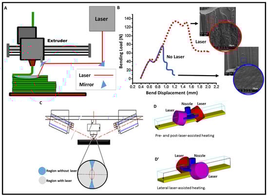
Figure 4.
Representative scheme of the in situ laser welding system with a mirror on the print head (A) []. Increased mechanical strength with and without in situ laser welding and micrographs of the region with and without welding (B). Representative diagram of the welding system with two lasers (C),Pre andpost-laser-asissisted heating (D) and lateral laser-assisted heating (D’) [].
The localized heating immediately before the deposition of the molten mass by the printing nozzle increases the diffusion of that mass, resulting in a 50% increase in relation to the part without the improvement in the weld, and improving the isotropy of printed parts manufactured with acrylonitrile-butadiene-styrene (ABS). There was an increase in the ductility of the parts printed with the laser, attributed to the increase in the interlayer interaction due to the interdiffusion, as observed in Figure 4B []. The inclusion of the laser, in addition to increasing the flexural strength, increases the elongation of the material, as observed through the bending displacement. Finally, in the highlight (Figure 4B), the images by scanning electron microscopy (SEM) of the surface with and without the laser reveal an increase in surface roughness, which may have contributed to the mechanical anchorage between the filaments. But since the small depth of the laser range, on the order of a few micrometers, results in a small range for the melting of the polymeric mass [], while increasing the laser power too much can cause degradation, Du et al. (2016) [] developed a system with two coupled lasers. A similar system was studied by Lee et al. (2021) [], in which two lasers were employed to create a preheating and postheating system.
The increase in temperature is directly related to the increase in laser power, but the laser power must be such that it allows the temperature to increase to the melting temperature (Tm) before the degradation temperature (Td). It is very difficult to establish efficient welding of crystalline materials such as PEEK, so the implementation of a laser system applied during the construction of printed parts can be an alternative to expand use of this polymer in ME. There was an increase in interlamellar shear strength of more than 45%, and the crystallinity was 2 times greater than that obtained without in situ laser treatment, approaching the typical PEEK crystallinity of 35% [,].
The path taken by the laser can be adjusted so that it only affects a portion of the part being fabricated []. This characteristic is especially important because during use, the part can be subjected to greater tension in a certain region than in another. Thus, it is possible to program a region with and without a laser, with the added benefit of increasing the laser lifetime. This makes it possible to optimize the equipment so there is no waste, in addition to applying different laser powers in regions with the highest voltage concentration.
4.1.2. Ultraviolet Irradiation (UV)
In the study carried out by Levenhagen et al. (2019) [], two changes were made to improve the weld, in which an increase in the maximum transverse stress was obtained compared to the pure nonirradiated sample. Since polymer molecules are large and complex, increasing the cooling speed of the polymeric mass, the amount of solder is reduced during the printing process. In this way, the inclusion of low-weight molecules can be used, resulting in a bimodal mixture. The submission of this mixture to an ultraviolet (UV) irradiation system during the ME process results in a sharp increase in the maximum transverse tensile stress of the printed parts, which can be 140 to 200% []. The control of the intensity of the radiation allows it to act in a balanced way in the formation of the covalent bonds and in the mobility of the polymeric chains to diffuse through the interface [,]. Figure 5 contains a representative diagram of this system, showing the molecules before and after the application of UV light on the left, and the system for application of UV light on the right.
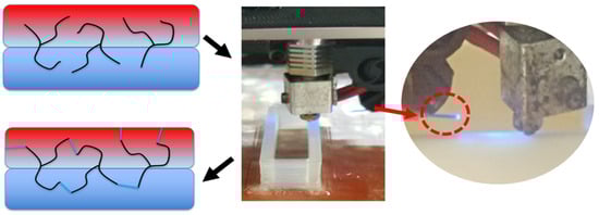
Figure 5.
Representative image of the molecules before and after UV exposure (on the left) and highlight in the UV light source (on the right). Reprinted (adapted) with permission from {Levenhagen and Dadmun, 2019} []. Copyright {2023} American Chemical Society.
Likewise, a UV resin curing system was developed by Yavitt et al. (2020) []. In this case, a dual system of UV and thermal curing of nanocomposites was used during and directly after ME by direct ink writing (DIW). An additive, chemically activated by UV or thermally activated by UV illumination to act as a curing initiator, was added to the polymeric matrix together with an acrylate resin and a barium sulfate filler having total reflection in the UV wavelength, facilitating the UV penetration. The authors reported that UV light allowed sufficient mobility of macromolecules and improved cure kinetics to diffuse and connect the final thermoset structure.
4.1.3. Infrared
Preheating has been adopted to improve the weld between adjacent filaments in large-scale and large-area ME. In this regard, Kishore et al. [] studied an improved in situ welding system composed of pyrometers and an infrared heating element (Figure 6A) [,]. The temperature gauges (pyrometers) measured the temperature before and after the lamps. The lamps, on the other hand, worked to heat the filament immediately before deposition of the next layer. In the system studied, ABS with carbon fiber was used and a more than twofold gain in fracture energy was observed under optimized conditions. The authors considered this the be an effective method to increase the temperature slightly above the Tg, improving the weld between the filaments.
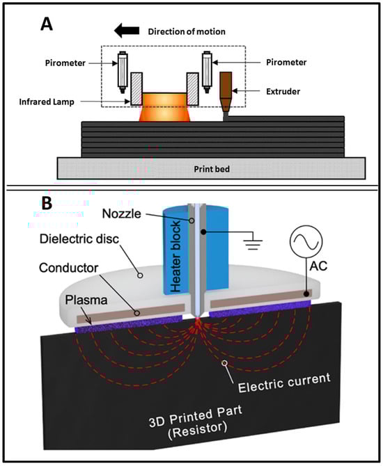
Figure 6.
(A) Representative scheme of in situ infrared heating in a large-scale printer []. (B) Representative scheme of the application of electric current in the printing nozzle and plasma formation. Reprinted (adapted) with permission from {Sweeney et al., 2020} []. Copyright {2023} American Chemical Society.
4.2. Electric Current
In Figure 6B, a representative diagram of the electrical current application system is shown, where dielectric disks are located in the nozzle itself. The electric current reaches the printed part in the region directly below the device and there is a concentration of current intensity in the region of the nozzle. The printed polymer part acts as a resistor, transforming electrical energy into thermal energy. Cold plasma formation is generated by dielectric barrier discharge, forming a plasma electrode around the print nozzle concentrically to induce heating of the material [].
The Z-force is increased and allows parts manufactured by printing not only to function as prototypes, but as final parts. As observed when applying in situ dielectric welding, it is possible to find resistance values similar to those used for manufacture by injection, only the elongation was lower compared to the injected part, but much higher compared to the system without welding. According to this study, the elastic modulus showed little difference in relation to tensile stress, but there was an increase in resistance with in situ welding, reaching similar values to those of injected parts. Finally, the elongation, despite the gain, was below that of the injected part. The gain in relation to tensile strength was 31% and in relation to plastic deformation yield, the increase was of the order of 250% compared to 3D printed parts [].
4.3. Radio Frequency Microwave
In the system proposed by Sweeney et al. (2017) [], The production of the printed part occurs in two stages. First, it involves carbon coating on the surface of the deposited filament, as seen in Figure 7A. The highlight in the image indicates that the Y and Z directions are weak, due to the dependence on the solder, whereas in the filament deposition axis (X axis), the part presents greater resistance and is stronger. Next, the part goes through a microwave postprocessing stage to improve the weld, as depicted in Figure 7B. Other studies can be found using microwaves as a postprocessing method with good results in welding [,,].
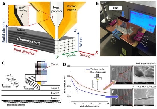
Figure 7.
Representative scheme of the carbon coating on the surface of the deposited filament (A) and microwave application in postprocessing (B) []. Representative scheme of the device for collecting heat radiating from the deposited layers (C). Increased heat retention resulting in improved weld (D) and SEM imaging with (E) and without (F) a heat collector [].
4.4. Devices for Induction Heating
A simpler in situ welding system was proposed by Hu et al. (2019) []. In this system, a collector retains the heat that comes out of the printing nozzle so that it is concentrated in the region of immediate printing, as shown in Figure 7C. As seen in Figure 7D, heat retention occurs efficiently, in which the temperature remains higher than in the system without the device. The micrographic images of the printed parts with and without a heat collector, in Figure 7C,D, respectively, reveal that the welding between the filaments was more efficient with the heat collector. There was formation of a region of greater contact between adjacent filaments. That study is particularly important since PEEK, an engineering polymer with high crystallinity making it difficult to apply in ME, was evaluated. Ravoori et al. (2019) [] developed a low-cost, low-complexity system that uses a metal block attached to the print head to serve as a preheating source. The metal block provides additional heat to the deposition area. Finally, in a doctoral dissertation, Patain (2007) [] designed a pre-deposition heating system using forced air. This system has not been widely explored in the literature.
5. In Situ Welding Improvement: Summary
Table 3 lists some studies that have described modifications to the solder during printing. Improvements in properties were achieved, where increase in tensile stress was cited the most. The most significant results were achieved by associating the modification of the polymeric matrix with an in situ welding device. Despite the gain in properties, there are still few works that have investigated the implementation of an in situ system for the improvement of polymeric welding. The simplest system employed was the heat collector []. The system using a double laser beam [] reached the highest values of mechanical properties without modifying the matrix (pure polymer).
Table 3.
Gain of properties with improvement of the in situ polymeric solder.
6. Conclusions
Studies focused on the development of devices to enhance in situ welding in material extrusion remain scarce. However, existing results demonstrate significant improvements in mechanical properties, even with the use of simple devices. These findings underscore the need for further research aimed at modifying 3D printers to incorporate such devices.
As the polymer matrix loses heat very abruptly, simply changing the properties of the polymers would not be enough. Modifications to the polymer matrix, through the formation of blends or composites, have enhanced weld strength by incorporating particles that retain heat or molecules with low molecular weight. However, modifications to the 3D printer are necessary to preheat the adjacent filament when deposited to obtain efficient welding between the filaments.
Devices utilizing light for preheating adjacent filaments have been the most employed for enhancing welding between deposited filaments. The simplest device, designed to retain heat in the welding region, showed some efficiency even when applied to complex polymers, such as engineering polymers. This device stands out for its ease of replication. It is plausible that evaluating other polymers with the same device could significantly enhance its efficiency.
In the context of filament welding, the best results were achieved through the combination of in situ welding and polymer matrix modification. Despite the limited number of studies focused on improving in situ welding, the results obtained highlight its relevance, as improvements were observed in all experiments conducted, including those using the simplest device.
Author Contributions
Conceptualization, M.d.N.d.C.; methodology, M.d.N.d.C.; validation, D.C.B., P.S.C.P. and E.V.D.G.L.; formal analysis, M.d.N.d.C.; investigation, M.d.N.d.C.; resources, J.A.-M. and M.d.N.d.C.; data curation, J.A.-M. and M.d.N.d.C.; writing—original draft preparation, M.d.N.d.C.; writing—review and editing, D.C.B., P.S.C.P. and E.V.D.G.L.; visualization, J.A.-M. and M.d.N.d.C.; supervision, E.V.D.G.L.; project administration, E.V.D.G.L. All authors have read and agreed to the published version of the manuscript.
Funding
This research received no external funding.
Data Availability Statement
The data that support the findings of this review can be found in the references cited throughout the manuscript.
Acknowledgments
The authors are grateful to the following Brazilian agencie National Council for Scientific and Technological Development—(CNPq) by financial support.
Conflicts of Interest
The authors declare no conflicts of interest.
References
- Parmar, H.; Khan, T.; Tucci, F.; Umer, R.; Carlone, P. Advanced robotics and additive manufacturing of composites: Towards a new era in industry 4.0. Mater. Manuf. Process. 2022, 37, 483–517. [Google Scholar] [CrossRef]
- Eyer, P.; Enzler, S.; Trauth, A.; Weidenmann, A. Investigating the mechanical properties of polymer samples from different additive manufacturing processed using ultrasonic phase spectroscopy. 3D Print. Addit. Manuf. 2022, 11, e666–e674. [Google Scholar] [CrossRef] [PubMed]
- Cardoso, P.H.M.; Teixeira, B.N.; Calado, V.M.A.; de Oliveira, M.G.; Mendonça, T.S.; Mendonça, R.H.; de Almeida, H.R.O.; Cunha, M.S.; Thiré, R.M.S.M. Mechanical and dimensional performance of poly (lactic acid) 3D-printed parts using thin spline interpolation. J. Appl. Polym. Sci. 2020, 137, 49171. [Google Scholar] [CrossRef]
- Espach, A.; Gupta, K. 3D Printing—An Important Industry 4.0 Tool for Online and Onsite Learning. In Artificial intelligence and online Engineering; Auer, M.E., El-Seoud, S.A., Karam, O.H., Eds.; REV 2022; Lecture Notes in Networks Systems; Springer: Cham, Switzerland, 2023; pp. 312–322. [Google Scholar] [CrossRef]
- Joseph, T.M.; Kallingal, A.; Suresh, A.M.; Mahapatra, D.K.; Hasanin, M.S.; Haponiuk, J.; Thomas, S. 3D printing of polylactic acid: Recent advances and opportunities. Int. J. Adv. Manuf. Technol. 2023, 125, 1015–1035. [Google Scholar] [CrossRef] [PubMed]
- Da Conceição, M.N.; Anaya-Mancipe, J.M.; Coelho, A.W.F.; Cardoso, P.H.M.; Thiré, R.M.S.M. Application of starch-rich mango by-product as filler for the development of an additive manufacturing filament compouond. Int. J. Biol. Macromol. 2024, 260, 129519. [Google Scholar] [CrossRef] [PubMed]
- Yusoff, N.H.M.; Chong, C.H.; Wan, Y.K.; Cheah, K.H.; Wong, V.L. Optimization strategies and emerging application of functionalized 3D-printed materials in water treatment: A review. J. Water Process Eng. 2023, 51, 103410. [Google Scholar] [CrossRef]
- Guo, H.; Lv, R.; Bai, S. Recent advances on 3D printing graphene-based composites. Nano Mater. Sci. 2019, 1, 101–115. [Google Scholar] [CrossRef]
- Azlin, M.N.N.; Ilyas, R.A.; Zuhri, M.Y.M.; Sapuan, S.M.; Harussani, M.M.; Sharma, S.; Nordin, A.H.; Nurazzi, N.N.; Afiqah, A.N. 3D printing and shaping polymers, composites, and nanocoposites: A review. Polymers 2022, 14, 180. [Google Scholar] [CrossRef] [PubMed]
- Coelho, A.W.F.; Thiré, R.M.S.M.; Araujo, A.C. Manufacturing of gypsum-sisal fiber composites using binder jetting. Addit. Manuf. 2019, 29, 101789. [Google Scholar] [CrossRef]
- Mandala, R.; Bannoth, A.P.; Akella, S.; Rangari, V.K.; Kodali, D. A short review on fused deposition modeling 3D printing of bio-based polymer nanocomposites. J. Appl. Polym. Sci. 2022, 139, 51904. [Google Scholar] [CrossRef]
- Saadi, M.A.S.R.; Magulre, A.; Pottackal, N.T.; Thakur, M.S.H.; Ikram, M.M.; Hart, A.J.; Ajayan, P.M.; Rahman, M.M. Direct ink writing: A 3D printing technology for diverse materials. Adv. Mater. 2022, 34, 2108855. [Google Scholar] [CrossRef]
- Hernandez, J.J.; Dobson, A.L.; Carberry, B.J. Controlled degradation of cast and 3-D printed photocurable thioester networks via thiol–thiolester exchange. Macromol. 2022, 55, 1376–1385. [Google Scholar] [CrossRef]
- ASTM F2792-12a; Standard Terminology for Additive Manufacturing Technologies. RAPID Manufacturing Institute: New York, NY, USA; ASTM International: West Conshohocken, PA, USA, 2013; pp. 10–12.
- Giordano, C.M.; Zancul, E.; Rodrigues, V.P. Análise dos custos da produção por manufatura aditiva em comparação a métodos convencionais. Produção Online 2016, 16, 499–523. [Google Scholar] [CrossRef]
- Salmoria, G.V.; Cardenuto, M.R.; Ahrens, C.H.; Lafratta, F. Prototipagem rápida por impressão 3D com resinas fotocuráveis: Uma análise sobre as tecnologias disponíveis no mercado nacional. In Anais do 9° Congresso Brasileiro de Polímeros; ABPol: São Carlos, Brazil, 2007; pp. 360–367. Available online: https://www.ipen.br/biblioteca/cd/cbpol/2007/PDF/79.pdf (accessed on 20 August 2024).
- ISO/ASTM52900-15; Standard Terminology for Additive Manufacturing—General Principles—Terminology. ASTM International: West Conshohocken, PA, USA, 2015; 9p.
- Balderrama-Armendariz, C.O.; MacDonald, E.; Espalin, D.; Cortez-Saenz, D.; Wicker, R.; Maldonado-Macias, A. Torsion analysis of the anisotropic behavior of FDM technology. Int. J. Adv. Manuf. Technol. 2018, 96, 307–317. [Google Scholar] [CrossRef]
- Navarrete, J.I.M.; Hidalgo-Salazar, M.A.; Nunez, E.E.; Arciniegas, A.J.R. Thermal and mechanical behavior of biocomposites using additive manufacturing. Int. J. Interact. Des. Manuf. 2018, 12, 449–458. [Google Scholar] [CrossRef]
- Kollamaram, G.; Croker, D.M.; Walker, G.M.; Goyanes, A.; Basit, A.; Gaisford, S. Low temperature fused deposition modeling (FDM) 3D printing of thermolabile drugs. Int. J. Pharm. 2018, 545, 144–152. [Google Scholar] [CrossRef]
- Tan, D.K.; Maniruzzaman, M.; Nokhodchi, A. Advanced Pharmaceutical Applications of Hot-Melt Extrusion Coupled with Fused Deposition Modelling (FDM) 3D Printing for Personalised Drug Delivery. Pharmaceutics 2018, 10, 203. [Google Scholar] [CrossRef]
- Crump, S. Apparatus and Method for Creating Three-Dimensional Objects. US5121329A, 9 June 1992. [Google Scholar]
- Milde, J.; Zaujec, R.; Hrušecký, R.; Zaujec, R.; Morovič, L.; Görög, A. Research of ABS and PLA materials in the process of fused deposition modeling method. In Proceedings of the 28th International Symposium on Intelligent Manufacturing and Automation, Zadar, Croatia, 8–11 November 2017; Volume 28, pp. 812–820. [Google Scholar] [CrossRef]
- Micó-Vicent, B.; Perales, E.; Huraibat, K.; Martínez-Verdú, M.; Viqueira, V. Maximization of FDM-3D-Objects gonio-appearance effects using PLA and ABS filaments and combining several printing parameters: “A case study”. Materials 2019, 12, 1423. [Google Scholar] [CrossRef] [PubMed]
- Claver, J.; Mar, A. The influence of manufacturing parameters on the mechanical behaviour of PLA and ABS pieces manufactured by FDM: A comparative analysis. Materials 2018, 11, 1333. [Google Scholar] [CrossRef]
- Panwar, A.; Tan, L.P. Current status of bioinks for micro-extrusion-based. Molecules 2016, 21, 685. [Google Scholar] [CrossRef] [PubMed]
- Zhu, P. Polymer Materials Via Melt Based 3D Printing: Fabrication and Characterization. Master’s Thesis, Clemson University, Clemson, SC, USA, 2018. Available online: https://tigerprints.clemson.edu/all_theses (accessed on 12 December 2024).
- Nonato, R.C.; Mei, L.H.I.; Bonse, B.C.; Chinaglia, E.F.; Morales, A.R. Nanocomposites of PLA containing ZnO nanofibers made by solvent cast 3D printing: Production and characterization. Eur. Polym. J. 2019, 114, 271–278. [Google Scholar] [CrossRef]
- Espalin, D.; Ramírez, J.A.; Medina, F.; Wicker, R. Multi-material, multi-technology FDM: Exploring build process variations. Rapid Prototyp. J. 2014, 20, 236–244. [Google Scholar] [CrossRef]
- Chist, S.; Schanbel, M.; Vorndran, E.; Groll, J.; Gbureck, U. Fiber reinforcement during 3D printing. Mater. Lett. 2015, 139, 165–168. [Google Scholar] [CrossRef]
- Spoerk, M.; Arbeiter, F.; Cajner, H.; Sapkota, J.; Holzer, C. Parametric optimization of intra- and inter-layer strengths in parts produced by extrusion-based additive manufacturing of poly(lactic acid). J. Appl. Polym. Sci. 2017, 134, 45401. [Google Scholar] [CrossRef]
- Kim, S.; Rahman, M.A.; Arifuzzaman, M.; Gilmer, D.B.; Li, B.; Wilt, J.K.; Lara-Curzio, E.; Saito, T. Closed-loop additive manufacturing of upcycled commodity plastic through dynamic cross-linking. Sci. Adv. 2022, 8, eabn6006. [Google Scholar] [CrossRef] [PubMed]
- Tian, X.; Liu, T.; Yang, C.; Wang, Q.; Li, D. Interface and performance of 3D printed continuous carbon fiber reinforced PLA composites. Compos. Part A Appl. Sci. Manuf. 2016, 88, 198–205. [Google Scholar] [CrossRef]
- Zhang, B.; Seong, B.; Hguyen, V.; Byun, D. 3D printing of high-resolution PLA-based structures by hybrid electrohydrodynamic and fused deposition modeling techniques. J. Micromech. Microeng. 2016, 26, 025015. [Google Scholar] [CrossRef]
- Onwubolu, G.C.; Rayegani, F. Characterization and Optimization of Mechanical Properties of ABS Parts Manufactured by the Fused Deposition Modelling Process. Int. J. Manuf. Eng. 2014, 2014, 598531. [Google Scholar] [CrossRef]
- Volpato, N. Prototipagem Rápida: Tecnologia e Aplicações, 1st ed.Edgard Blucher LTDA: São Paulo, Brazil, 2006. [Google Scholar]
- Faes, M.; Ferraris, E.; Moens, D. Influence of inter-layer cooling time on the quasi-static properties of ABS components produced via fused deposition modelling. Procedia CIRP 2016, 42, 748–753. [Google Scholar] [CrossRef]
- Contanzo, A.; Poggi, A.; Looijmans, S.; Venkatraman, D.V.; Sawyer, D.; Puskar, L.; Mcllroy, C.; Cavallo, D. The role of molar mass in achieving isotropy and inter-layer strength in mat-ex printed polylactic acid. Polymers 2022, 14, 2792. [Google Scholar] [CrossRef]
- Tiwary, V.K.; Arunkumar, P.; Malik, V.R. An overview on joining/welding as post-processing technique to circumvent the build volume limitation of an FDM-3D printer. Rapid Prototyp. J. 2021, 27, 808–821. [Google Scholar] [CrossRef]
- Dodin, M.G. Welding Mechanisms of Plastics: A Review. J. Adhes. 1981, 12, 99–111. [Google Scholar] [CrossRef]
- Adhikari, S.; Durning, C.J.; Fish, J.; Simon, J.W.; Kumar, S.K. Modeling Thermal Welding of Semicrystalline Polymers. Macromolecules 2022, 55, 1719–1725. [Google Scholar] [CrossRef]
- da Costa, A.P.; Botelho, E.C.; Costa, M.L.; Narita, N.E.; Tarpani, J.R. A review of welding technologies for thermoplastic composites in aerospace applications. J. Aerosp. Technol. Manag. 2012, 4, 255–265. [Google Scholar] [CrossRef]
- Wool, R.P.; Yuan, B.L.; McGarel, O.J. Welding of polymer interfaces. Polym. Eng. Sci. 1989, 29, 1340–1367. [Google Scholar] [CrossRef]
- Ageorges, C.; Ye, L.; Hou, M. Advances in fusion bonding techniques for joining thermoplastic matrix composites: A review. Composites 2001, 32 Pt A, 839–857. [Google Scholar] [CrossRef]
- Grewell, D.; Benatar, A. Welding of plastics: Fundamentals and new developments. Int. Polym. Process. 2007, 22, 43–60. [Google Scholar] [CrossRef]
- Xiong, X.; Wang, D.; Wei, J.; Zhao, P.; Ren, R.; Dong, J.; Cui, X. Resistance welding technology of fiber reinforced polymer composites: A review. J. Adhes. Sci. Technol. 2021, 35, 1593–1619. [Google Scholar] [CrossRef]
- Sercer, M.; Raos, P. Joining of Plastic and Composites. In Encyclopedia of Life Support Welding Engineering and Technology; Eolss Publishers (Under the Auspices of the UNECO): Oxford, UK, 2010. [Google Scholar]
- Stokes, V.K. Joining Methods for Plastics and Plastic Composites: An Overview. Polym. Eng. Sci. 1989, 29, 1310–1324. [Google Scholar] [CrossRef]
- de Pelsmaeker, J.; Graulus, G.J.; Van Vlierberghe, S.; Thienpont, H.; Van Hermelrijck, D.; Dubruel, P.; Ottevaere, H. Clear to clear laser welding for joining thermoplastic polymers: A comparative study based on physicochemical characterization. J. Mater. Process Technol. 2018, 255, 808–815. [Google Scholar] [CrossRef]
- Acherjee, B. Laser transmission welding of polymers—A review on process fundamentals, material attributes, weldability, and welding techniques. J. Manuf. Process. 2020, 60, 227–246. [Google Scholar] [CrossRef]
- de Baere, I.; Allaer, K.; Jacques, S.; Van Paepegem, V.; Degrieck, J. Interlaminar Behavior of Infrared Welded Joints of Carbon Fabric–Reinforced Polyphenylene Sulfide. Polym. Compos. 2012, 33, 1105–1113. [Google Scholar] [CrossRef]
- Khmelev, V.N.; Slivin, A.N.; Lehr, A.V.; Abramov, A.D. Theoretical investigations of continuous ultrasonic seam welding of thermoplastic polymers and fabrics. In Proceedings of the 2010 11th International Conference and Seminar on Micro/Nanotechnologies and Electron Devices 2010, EDM’2010—Proceedings, Novosibirsk, Russia, 30 June–4 July 2010; pp. 341–344. [Google Scholar] [CrossRef]
- Tofangchi, A.; Han, P.; Izquierdo, J.; Iyengar, A.; Hsu, K. Effect of ultrasonic on interlayer adhesion in fused filament fabrication 3D printed ABS. Polymers 2019, 11, 315. [Google Scholar] [CrossRef] [PubMed]
- Yu, K.; Shi, Q.; Li, H.; Jabour, J.; Yang, H.; Dunn, M.L.; Wang, T.; Qi, H.J. Interfacial welding of dynamic covalent network polymers. J. Mech. Phys. Solids. 2016, 94, 1–17. [Google Scholar] [CrossRef]
- Cunha, M.A.G.; Robbins, M.O. Effect of Flow-Induced Molecular Alignment on Welding and Strength of Polymer Interfaces. Macromolecules 2020, 53, 8417–8427. [Google Scholar] [CrossRef]
- Avenet, J.; Cender, T.A.; Le Corre, S.; Bailleul, J.L.; Levy, A. Experimental correlation of rheological relaxation and interface healing times in welding thermoplastic PEKK composites. Compos. Part A Appl. Sci. Manuf. 2021, 149, 106489. [Google Scholar] [CrossRef]
- Anderson, K.L.; Wescott, J.T.; Carver, T.J.; Windle, A.H. Mesoscale modelling of polymer welding. Mater. Sci. Eng. A 2004, 365, 14–24. [Google Scholar] [CrossRef]
- Coasey, K.; Hart, K.R.; Wetzel, E.; Edwards, D.; Mackay, M.E. Nonisothermal welding in fused filament fabrication. Addit. Manuf. 2020, 33, 101140. [Google Scholar] [CrossRef]
- Yokomizo, K.; Banno, Y.; Kotaki, M. Molecular dynamics study on the effect of molecular orientation on polymer welding. Polymer 2012, 53, 4280–4286. [Google Scholar] [CrossRef]
- McIlroy, C.; Olmsted, P.D. Disentanglement effects on welding behaviour of polymer melts during the fused-filament-fabrication method for additive manufacturing. Polymer 2017, 123, 376–391. [Google Scholar] [CrossRef]
- Fitzharris, E.R.; Watt, I.; Rosen, D.W.; Shofner, M.L. Interlayer bonding improvement of material extrusion parts with polyphenylene sulfide using the Taguchi method. Addit. Manuf. 2018, 24, 287–297. [Google Scholar] [CrossRef]
- Canevarolo, S.V., Jr. Polymer Science: A Textbook for Engineers and Technologists, 1st ed.; Hanser Publications: Cincinnati, OH, USA, 2020; pp. 149–188. [Google Scholar]
- Srinivas, V.; Hooy-Corstjens, C.S.J.V.; Vaughan, G.B.M.; Leeuwen, B.V.; Rastogi, S.; Harings, J.A.W. Interfacial stereocomplexation to strengthen fused deposition modeled Poly(lactide) welds. ACS Appl. Polym. Mater. 2019, 1, 2131–2139. [Google Scholar] [CrossRef]
- Das, A.; Gilmer, E.L.; Biria, S.; Bortner, M.J. Importance of polymer rheology on material extrusion additive manufacturing: Correlating process physics to print properties. ACS Appl. Polym. Mater. 2021, 3, 1218–1249. [Google Scholar] [CrossRef]
- Seppala, J.E.; Migler, K.D. Infrared thermography of welding zones produced by polymer extrusion additive manufacturing. Addit. Manuf. 2016, 12, 71–76. [Google Scholar] [CrossRef] [PubMed]
- Ko, Y.S.; Herrmann, D.; Tolar, O.; Elspass, W.J. Improving the filament weld-strength of fused filament fabrication products through improved interdiffusion. Addit. Manuf. 2019, 29, 100815. [Google Scholar] [CrossRef]
- Srinivas, V.; Hooy-Corstjens, C.S.J.V.; Rastogi, S.; Harings, J.A.W. Promotion of molecular diffusion and/or crystallization in fused deposition modeled poly(lactide) welds. Polymer 2020, 202, 122637. [Google Scholar] [CrossRef]
- Vaes, D.; Puyvelde, P.V. Semi-crystalline feedstock for filament-based 3D printing of polymers. Prog. Polym. Sci. 2021, 118, 101411. [Google Scholar] [CrossRef]
- Go, J.; Schiffres, S.N.; Stevens, A.G.; Hart, A.J. Rate limits of additive manufacturing by fused filament fabrication and guidelines for high-throughput system design. Addit. Manuf. 2017, 16, 1–11. [Google Scholar] [CrossRef]
- Kumar, R.; Singh, R.; Ahuja, I.P.S. Investigations of mechanical, thermal and morphological properties of FDM fabricated parts for friction welding applications. Measurement 2018, 120, 11–20. [Google Scholar] [CrossRef]
- Sun, Q.; Rizvi, G.M.; Bellehumeur, C.T.; Gu, P. Experimental study of the cooling characteristics of polymer filaments in FDM and impact on the mesostructures and properties of prototypes. Int. Solid. Free Fabr. Symp. 2003, 14, 312–323. [Google Scholar] [CrossRef]
- ASTM D1938-19; Standard Test Method for Tear-Propagation Resistance (Trouser Tear) of Plastic Film and Thin Sheeting by a Single-Tear Method. ASTM International: West Conshehoken, PA, USA, 2019.
- Davis, C.S.; Hillgartner, K.E.; Han, S.H.; Seppala, J.E. Mechanical strength of welding zones produced by polymer extrusion additive manufacturing. Addit. Manuf. 2017, 16, 162–166. [Google Scholar] [CrossRef] [PubMed]
- Costanzo, A.; Croce, U.; Spotorno, R.; Fenni, S.E.; Cavallo, D. Fused deposition modeling of polyamides: Crystallization and weld formation. Polymers 2020, 12, 2980. [Google Scholar] [CrossRef] [PubMed]
- Abbott, A.C.; Tandon, G.P.; Bradford, R.L.; Koerner, H.; Baur, J.W. Process-structure-property effects on ABS bond strength in fused filament fabrication. Addit. Manuf. 2018, 19, 29–38. [Google Scholar] [CrossRef]
- Javadi, M.S.; Ehteshamfar, M.V.; Adibi, H. A compressive analysis and prediction of the effect of groove shape and volume fraction of multi-walled carbon nanotubes on the polymer 3D-printed parts in the friction stir welding process. Polym. Test. 2023, 117, 107844. [Google Scholar] [CrossRef]
- Allum, J.; Moetazedian, A.; Gleadall, A.; Silberschmidt, V. Interlayer bonding has bulk-material strength in extrusion additive manufacturing: New understanding of anisotropy. Addit. Manuf. 2020, 34, 101297. [Google Scholar] [CrossRef]
- Seppala, J.E.; Han, S.H.; Hillgartner, K.E.; Davis, C.S.; Migler, K.B. Weld Formation During Material Extrusion Additive Manufacturing. Soft Matter. 2017, 13, 6761–6769. [Google Scholar] [CrossRef] [PubMed]
- Oskolkov, A.A.; Bezukladnikov, I.I.; Trushnikov, D.N. Mathematial Model of the Layer-by-Layer FFF/FGF Polymer Extrusion Process for Use in the Algorithm of Numerical Implementation of Real-Time Thermal Cycle Control. Polymers 2023, 15, 4518. [Google Scholar] [CrossRef]
- Baouch, Z.; Vezzoli, R.; Koster, J.; Costanzo, A.; Lanfranchi, A.; Cavallo, D.; Mcilroy, C. Polypropylene for material extrusion: Evidence that flow-enhanced crystallization restricts welding. Addit. Manuf. 2024, 83, 104063. [Google Scholar] [CrossRef]
- Srinivas, V.; Hooy-Corstjens, C.S.J.V.; Harings, J.A.W. Correlating molecular and Crystallization Dynamics to Macroscopic fusion and Thermodynamic Stability in Fused Deposition Modeling; A Model Study on Polylactides. Polymer 2018, 142, 348–355. [Google Scholar] [CrossRef]
- Sweeney, C.B.; Burnette, M.L.; Pospisil, M.J.; Shah, S.A.; Anas, M.; Teipel, B.R.; Zahner, B.S.; Staack, D.; Green, M.J. Dielectric Barrier Discharge Applicator for Heating Carbon Nanotube-Loaded Interfaces and Enhancing 3D-Printed Bond Strength. Nano Lett. 2020, 20, 2310–2315. [Google Scholar] [CrossRef] [PubMed]
- Costanzo, A.; Spotorno, R.; Candal, M.V.; Fernández, M.M.; Muller, A.J.; Graham, R.S.; Cavallo, R.; McIlroy, C. Residual alignment and its effect on weld strength in material-extrusion 3D-printing of polylactic acid. Addit. Manuf. 2020, 36, 101415. [Google Scholar] [CrossRef]
- Moritzer, E.; Wächter, J. Development of a Procedure for the Assessment of Material Potentials Under Consideration of the Weld Seam Quality for Multi-material Applications in the FDM Process. Macromol. Symp. 2020, 404, 2100389. [Google Scholar] [CrossRef]
- Nogales, A.; Gutiérrez-Fernández, E.; García-Gutiérrez, M.C.; Ezquerra, T.A.; Rebollar, E.; Šics, I.; Malfois, M.; Gaidukovs, S.; Gecis, E.; Celms, K.; et al. Structure development in polymers during fused filament fabrication (FFF): An inSitu small- and wide-angle X-ray scattering study synchrotron. Macromolecules 2019, 52, 9715–9723. [Google Scholar] [CrossRef]
- Dave, H.K.; Prajapati, A.R.; Rajpurohit, S.R.; Patadiya, N.H.; Raval, H.K. Investigation on tensile strength and failure modes of FDM printed part using in-house fabrication PLA filament. Adv. Mater. Process Technol. 2022, 8, 576–597. [Google Scholar] [CrossRef]
- Park, S.J.; Lee, J.E.; Park, J.; Lee, N.K.; Son, Y.; Park, S.H. High temperature 3D printing of polyetheretherketone products: Perspective on industrial manufacturing applications of super engineering plastics. Mater. Des. 2021, 211, 110163. [Google Scholar] [CrossRef]
- Levenhagen, N.P.; Dadmun, M.D. Interlayer diffusion of surface segregating additives to improve the isotropy of fused deposition modeling products. Polymer 2018, 152, 35–41. [Google Scholar] [CrossRef]
- Rodzeń, K.; Harkin-Jones, E.; Wegrzyn, M.; Sharma, P.K.; Zhigunov, A. Improvement of the layer-layer adhesion in FFF 3D printed PEEK/carbon fibre composites. Compos. Part A Appl. Sci. Manuf. 2021, 149, 106532. [Google Scholar] [CrossRef]
- Kurapati, S.K.; Reddy, N.M.; Sujithra, R.; Kola, R.; Ramesh, G.V.; Saritha, D. Nanomaterials and Nanostructures in Additive Manufacturing: Properties, Applications, and Technological Changes. In Nanotechnology-Based Additive Manufacturing: Product Design, Properties and Application; Deshmukh, K., Khadheer, S.K., Sadasivuni, K., Eds.; Wiley-VCH GmbH: Weinheim, Germany, 2023; Volume 2, pp. 53–102. [Google Scholar] [CrossRef]
- Ravi, A.K.; Deshpande, A.; Hsu, K.H. An in-process laser localized pre-deposition heating approach to inter-layer bond strengthening in extrusion based polymer additive manufacturing. J. Manuf. Process. 2016, 24, 179–185. [Google Scholar] [CrossRef]
- Luo, M.; Tian, X.; Zhu, W.; Li, D. Controllable interlayer shear strength and crystallinity of PEEK components by laser-assisted material extrusion. J. Mater. Res. 2018, 33, 1632–1641. [Google Scholar] [CrossRef]
- Menga, L.; Xiaoyong, T.; Junfan, S.; Weijun, Z.; Dichen, L.; Yingjie, Q. Impregnation and interlayer bonding behaviours of 3D-printed continuous carbon-fiber-reinforced poly-ether-ether-ketone composites. Compos. Part A 2019, 121, 2019. [Google Scholar] [CrossRef]
- Chen, Y.; Shan, Z.; Yang, X.; Fan, C.; Song, Y. Influence of preheating temperature and printing speed on interlaminar shear performance of laser-assisted additive manufacturing for CCF/PEEK composites. Polym. Compos. 2022, 43, 3412. [Google Scholar] [CrossRef]
- Han, P.; Torabnia, S.; Riyad, M.F.; Bawareth, M.; Hsu, K. Effect of laser heating on mechanical strength of carbon fiber–reinforced nylon in fused filament fabrication. J. Adv. Manuf. Technol. 2024, 133, 6139–6146. [Google Scholar] [CrossRef]
- Han, P.; Tofangchi, A.; Deshpande, A.; Zhang, S.; Hsu, K. An approach to improve interface healing in FFF-3D printed ultem 1010 using laser pre-deposition heating. Procedia Manuf. 2019, 34, 672–677. [Google Scholar] [CrossRef]
- Han, P.; Tofagangchi, A.; Zhang, S.; Desphande, A.; Hsu, K. Effect of in-process laser interface heating on strength osotropy of extrusion-based additively manufactured PEEK. Procedia Manuf. 2020, 48, 737–742. [Google Scholar] [CrossRef]
- Mundada, P.S.; Yang, C.H.; Chen, R.K. Investigation of the effects of a pre-deposition heating system on the interfacial temperature and interlayer bonding strength for fused filament fabrication. Rapid Prototyp. J. 2023, 29, 9–18. [Google Scholar] [CrossRef]
- Han, P.; Tofangchi, A.; Zhang, S.; Izquierdo, J.J.; Hsu, K. Interface Healing Between Adjacent Tracks in Fused Filament Fabrication Using In-Process Laser Heating. 3D Print. Addit. Manuf. 2023, 10, 808–815. [Google Scholar] [CrossRef] [PubMed]
- Han, P.; Zhang, S.; Yang, Z.; Riyad, M.F.; Popa, D.O.; Hsu, K. In-Process Orbiting Laser-Assisted Technique for the Surface Finish in Material Extrusion-Based 3D Printing. Polymers 2023, 15, 2221. [Google Scholar] [CrossRef]
- Levenhagen, N.P.; Dadmun, M.D. Reactive Processing in Extrusion-Based 3D Printing to Improve Isotropy and Mechanical Properties. Macromolecules 2019, 52, 6495–6501. [Google Scholar] [CrossRef]
- Du, J.; Zhengying, W.; Xin, W.; Jijie, W.; Zhen, C. An improved fused deposition modeling process for forming large-size thin-walled parts. J. Mater. Process Technol. 2016, 234, 332–341. [Google Scholar] [CrossRef]
- Lee, J.E.; Park, S.J.; Son, Y.; Park, K.; Park, S.H. Mechanical reinforcement of additive-manufactured constructs using in situ auxiliary heating process. Addit. Manuf. 2021, 43, 101995. [Google Scholar] [CrossRef]
- Porto, G.A.; de Paula, L.G.A.; Arias, J.J.R.; Chaves, E.G.; Marques, M.F.V. Comparative analysis of poly(ether-ether-ketone) properties aged in different conditions for application in pipelines. J. Therm. Anal. Calorim. 2023, 148, 79–95. [Google Scholar] [CrossRef]
- Levenhagen, N.P.; Dadmun, M.D. Bimodal molecular weight samples improve the isotropy of 3D printed polymeric samples. Polymer 2017, 122, 232–241. [Google Scholar] [CrossRef]
- Zhu, G.; Hou, Y.; Xu, J.; Zhao, N. Digital light processing 3D printing of enhanced polymers via interlayer welding. Macromol. Rapid Commun. 2022, 43, 2200053. [Google Scholar] [CrossRef]
- Yavitt, B.M.; Wiegart, L.; Salatto, D.; Huang, Z.; Endoh, M.K.; Poeller, S.; Petrash, S.; Koga, T. Structural Dynamics in UV Curable Resins Resolved by in Situ 3D Printing X-ray Photon Correlation Spectroscopy. ACS Appl. Polym. Mater. 2020, 2, 4096–4108. [Google Scholar] [CrossRef]
- Kishore, V.; Ajinjeru, C.; Nycz, A.; Post, B.; Lindahl, J.; Kunc, V.; Duty, C. Infrared preheating to pmprove interlayer strength of big area additive manufacturing (BAAM) components. Addit. Manuf. 2017, 14, 7–12. [Google Scholar] [CrossRef]
- Nycza, A.; Kishore, V.; Lindahl, J.; Duty, C.; Carnal, C.; Kunch, V. Controlling substrate temperature with infrared heating to improve mechanical properties of large-scale printed parts. Addit. Manuf. 2020, 33, 101068. [Google Scholar] [CrossRef]
- Luchinsky, D.G.; Hafiychuk, H.; Hafiychuk, V.; Chaki, K.; Nitta, H.; Ozawa, T.; Wheeler, K.R.; Prater, T.J.; McClintock, P.V.E. Welding dynamics in an atomistic model of an amorphous polymer blend with polymer-polymer interface. J. Polym. Sci. 2020, 58, 2051–2061. [Google Scholar] [CrossRef]
- Sweeney, C.B.; Lackey, B.A.; Pospisil, M.J.; Acheé, T.C.; Hicks, V.K.; Teipel, B.R.; Saed, M.A.; Green, M.J. Welding of 3D-printed carbon nanotube–polymer composites by locally induced microwave heating. Sci. Adv. 2017, 3, e1700262. [Google Scholar] [CrossRef]
- Pei, H.; Chen, Y.; Lv, Q.; Peng, Z.; Wang, X.; Chen, N.; Zhang, H. A novel microwave assisted multi-material 3D printing strategy to architect lamellar piezoelectric generators for intelligent sensing. Compos. Part B 2024, 280, 111529. [Google Scholar] [CrossRef]
- Palaniyappan, S.; Sivakumar, N.K.; Rajakumar, S.; Mohan, D.G.; Rahaman, M. Ultrasonic welding of Cork Wood/PLA composites: Effect of welding factors on lap shear strength performance. J. Adhes. Sci. Technol. 2024, 17, 1–20. [Google Scholar] [CrossRef]
- Rana, R.S.; Singh, I.; Sharma, A.K. Ultrasonic welding of printed/molded sustainable polymer specimens with energy directors. Ultrasonics 2023, 134, 107078. [Google Scholar] [CrossRef]
- Hu, B.; Duan, X.; Xing, Z.; Xu, Z.; Du, C.; Zhou, H.; Chen, R.; Shan, B. Improved design of fused deposition modeling equipment for 3D printing of high-performance PEEK parts. Mech. Mater. 2019, 137, 103139. [Google Scholar] [CrossRef]
- Ravoori, D.; Prajapati, H.; Talluru, V.; Adnan, A.; Jain, A. Nozzle-integrated pre-deposition and post-deposition heating of previously deposited layers in polymer extrusion based additive manufacturing. Addit. Manuf. 2019, 28, 719–726. [Google Scholar] [CrossRef]
- Partain, S.C. Fused Deposition Modeling with Localized Pre-Deposition Heating Using Forced Air. Master’s Thesis, Montana State University-Bozeman, College of Engineering, Bozeman, MT, USA, 2007. [Google Scholar]
- Layher, M.; Lukas, E.; Linke, D.; Hopf, A.; Bliedtner, J. Laser beam heat treatment in large-scale additive manufacturing. Prog. Addit. Manuf. 2023, 8, 1489–1499. [Google Scholar] [CrossRef]
Disclaimer/Publisher’s Note: The statements, opinions and data contained in all publications are solely those of the individual author(s) and contributor(s) and not of MDPI and/or the editor(s). MDPI and/or the editor(s) disclaim responsibility for any injury to people or property resulting from any ideas, methods, instructions or products referred to in the content. |
© 2025 by the authors. Licensee MDPI, Basel, Switzerland. This article is an open access article distributed under the terms and conditions of the Creative Commons Attribution (CC BY) license (https://creativecommons.org/licenses/by/4.0/).