
An Automatic Recognition Approach for Tapping States Based on Object Detection


Abstract
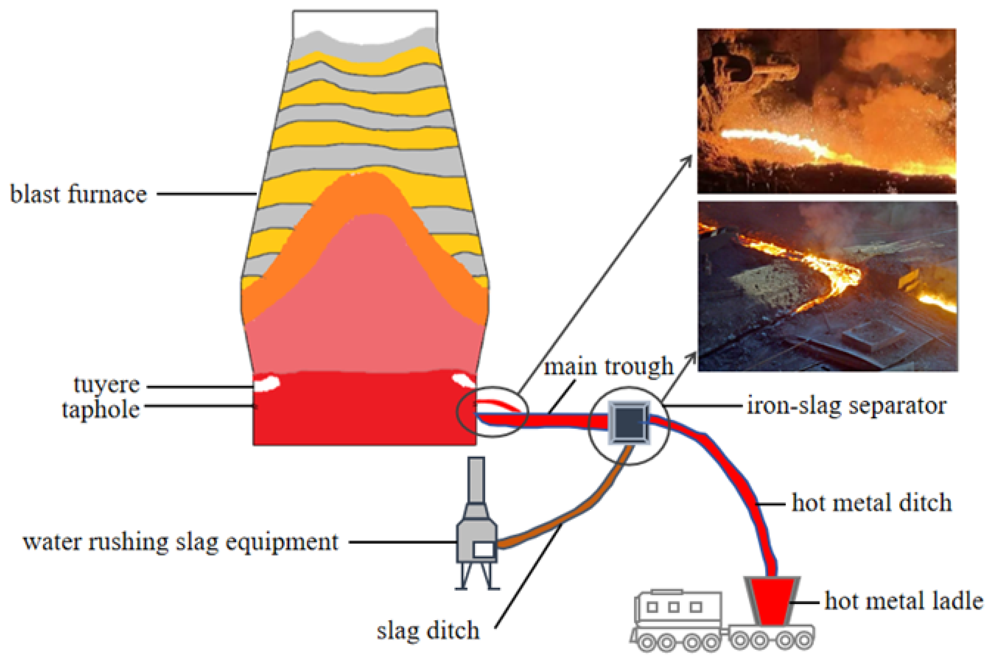
1. Introduction
- We revisit the problem of tapping-state recognition and transform it into an object detection task. This approach not only enhances the recognition accuracy but also improves its interpretability. It is the first effective attempt in utilizing deep image processing technology for tapping-state recognition, which provides a new idea for future research.
- We introduce a YOLOX-based object detection model tailored for tapping-state recognition. Additionally, we propose an online scheduling strategy that enables real-time recognition and accurate calculation of key monitoring data. Experimental results demonstrate that our model can achieve a recognition accuracy of 99.8%.
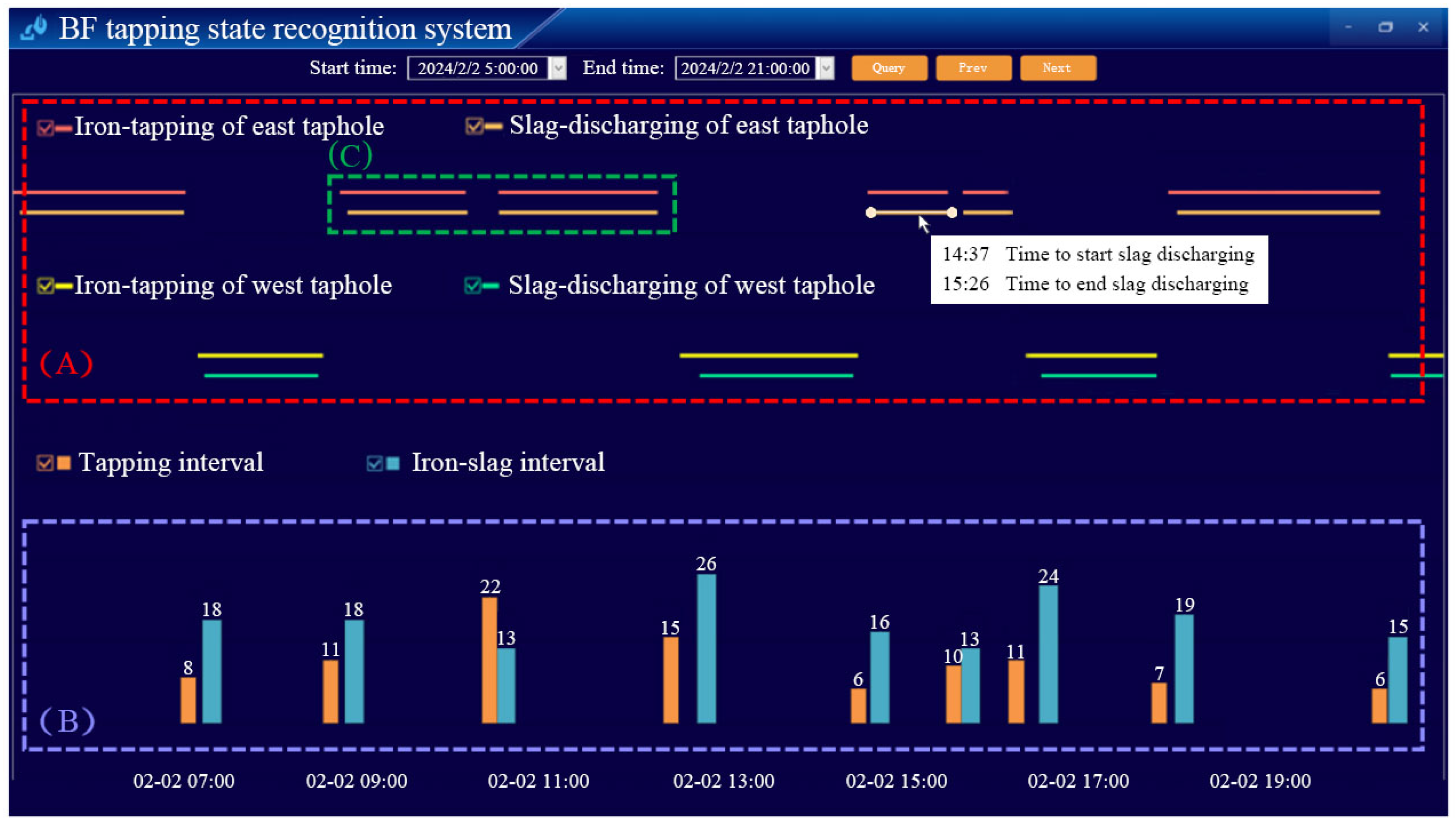
- We have developed a comprehensive tapping-state recognition system that has been successfully applied in engineering projects. The intuitive data dashboard seamlessly integrates real-time tapping states and key monitoring data from multiple tapholes, offering a holistic view of the tapping operation and real-time insights for operational optimization in BF production.
2. Our Method
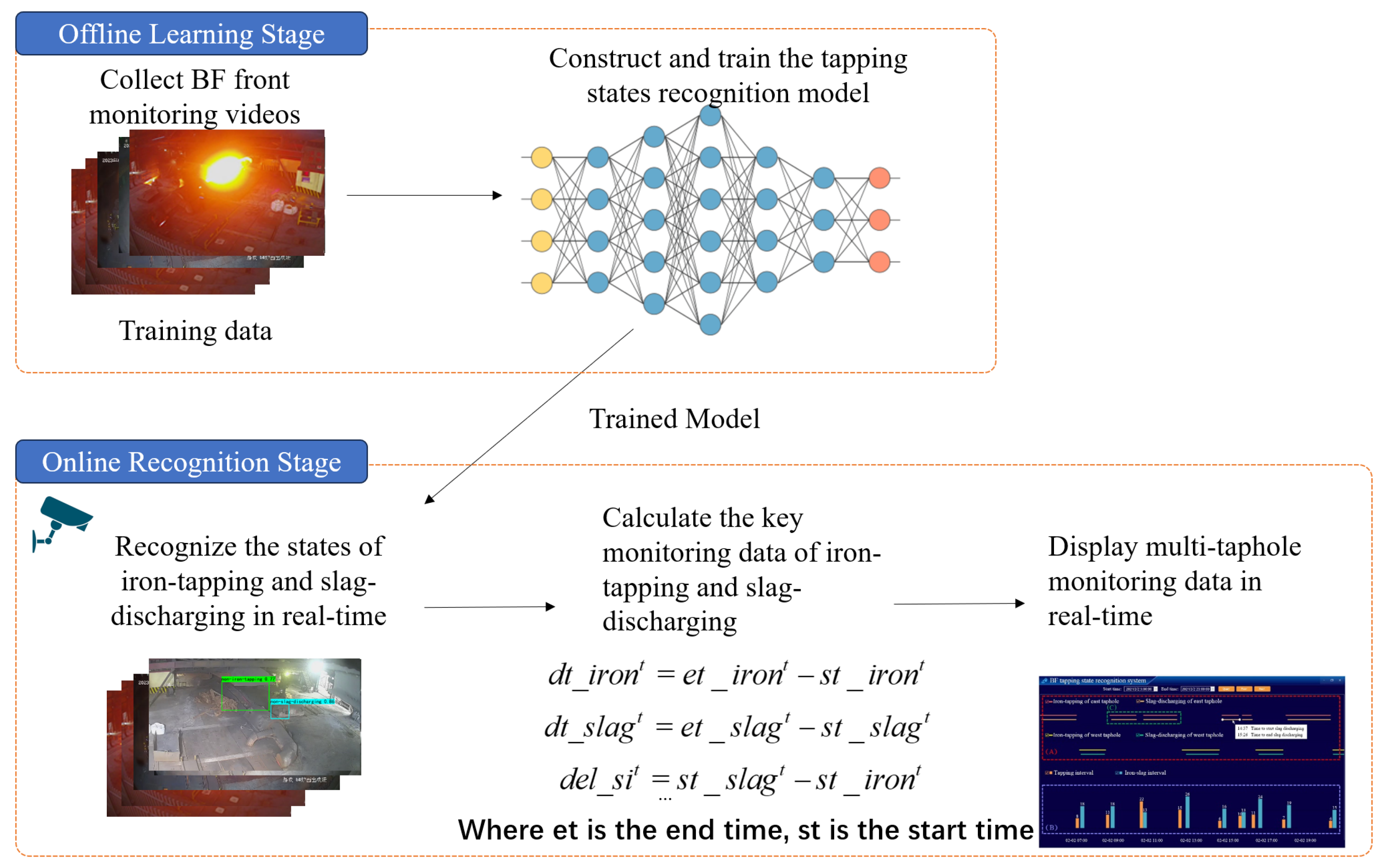
2.1. Offline Learning Stage
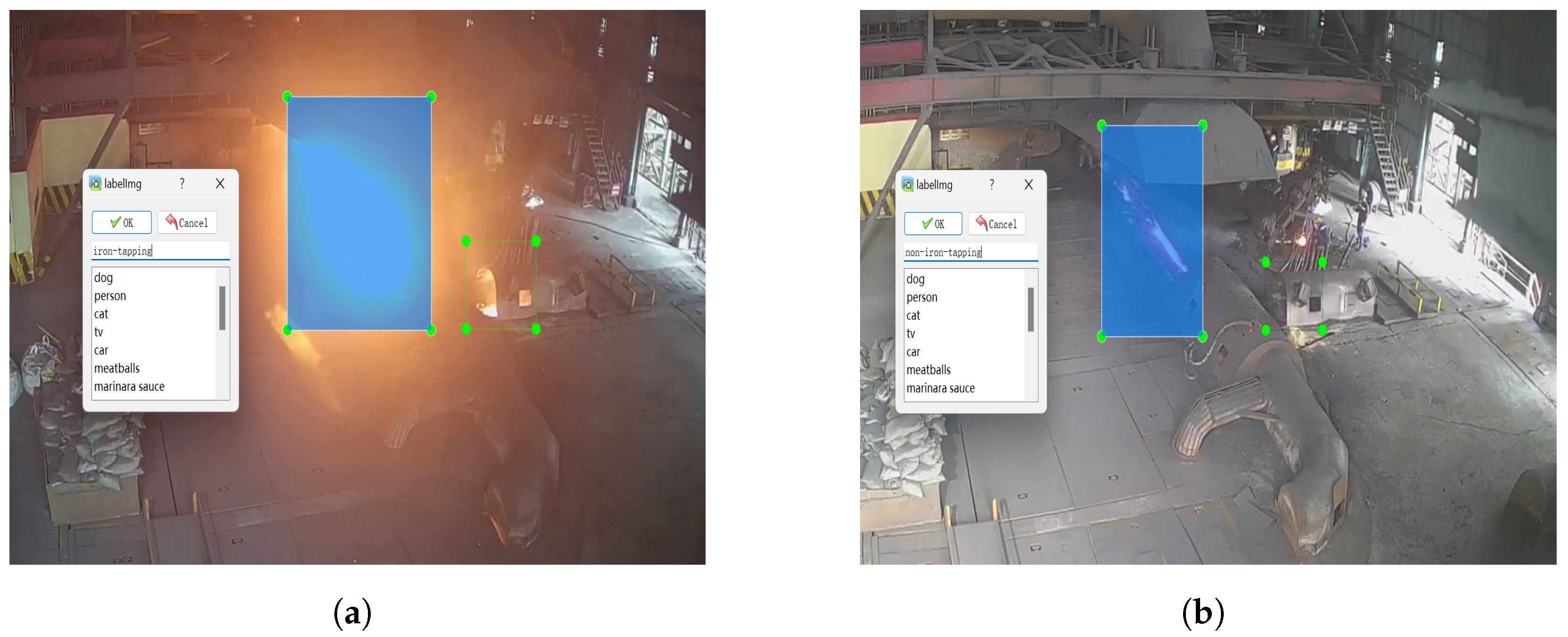
2.1.1. Annotation of BF Front Monitoring Images
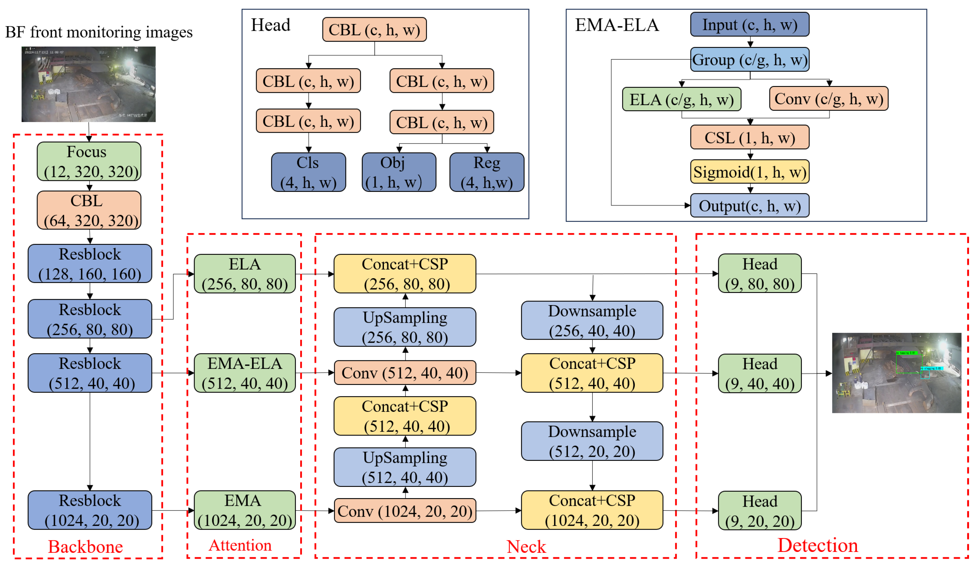
2.1.2. Structure of the Tapping-State Recognition Model
2.1.3. Model Training and Inference
2.2. Online Recognition Stage
2.2.1. Calculation of Key Monitoring Data
2.2.2. Real-Time Scheduling with Multiple Threads
3. Method Validation
3.1. Data Preparation and Evaluation Metrics
3.2. Experimental Results of Tapping States Recognition
3.2.1. Comparing to Existing Methods
3.2.2. Model Validation During the State Changing
3.2.3. Model Validation Under Changing Camera Position
3.3. Experimental Results of Deviation of Monitoring Data
4. Engineering Application
5. Conclusions
Author Contributions
Funding
Data Availability Statement
Conflicts of Interest
References
- Smith, M.P. Blast furnace ironmaking—A view on future developments. Procedia Eng. 2017, 174, 19–28. [Google Scholar] [CrossRef]
- Lu, Z.; Gu, H.; Chen, L.; Liu, D.; Yang, Y.; McLean, A. A review of blast furnace iron-making at Baosteel facilities. Ironmak. Steelmak. 2019, 46, 618–624. [Google Scholar] [CrossRef]
- Frischer, R.; Grycz, O.; Hlavica, R. Concept industry 4.0 in metallurgical engineering. In Proceedings of the 26th International Conference on Metallurgy and Materials (METAL), Brno, Czech Republic, 24–26 May 2017. [Google Scholar]
- Zhou, P.; Song, H.; Wang, H.; Chai, T. Data-driven nonlinear subspace modeling for prediction and control of molten iron quality indices in blast furnace ironmaking. IEEE Trans. Control Syst. Technol. 2016, 25, 1761–1774. [Google Scholar] [CrossRef]
- Li, H. Online Detection Method for Iron Status in Blast Furnace Slag Discharge. Patent CN110184401A, 25 December 2020. [Google Scholar]
- Li, X. A Monitoring Method and System for the Status of Blast Furnace Tapping Hole. Patent CN 113122669 B, 16 July 2021. [Google Scholar]
- Zong, Y.; Wang, Z.; Liu, X.; Nian, Y.; Pan, J.; Zhang, C.; Wang, Y.; Chu, J.; Zhang, L. Judgment of blast furnace iron-tapping status based on data differential processing and dynamic window analysis algorithm. Prog. Nat. Sci. Mater. Int. 2023, 33, 450–457. [Google Scholar] [CrossRef]
- Zong, Y.; Hu, S.; Qin, D.; Wang, Z.; Zhang, C.; Chu, J.; Zhang, L. Iron-Tapping State Recognition of Blast Furnace Based on Bi-GRU Composite Model and Post-processing Classifier. IEEE Sens. J. 2023, 23, 22006–22018. [Google Scholar] [CrossRef]
- He, K.; Zhang, X.; Ren, S.; Sun, J. Deep residual learning for image recognition. In Proceedings of the IEEE Conference on Computer Vision and Pattern Recognition, Las Vegas, NV, USA, 27–30 June 2016; pp. 770–778. [Google Scholar]
- Huang, G.; Liu, Z.; Van Der Maaten, L.; Weinberger, K.Q. Densely connected convolutional networks. In Proceedings of the IEEE Conference on Computer Vision and Pattern Recognition, Honolulu, HI, USA, 21–26 July 2017; pp. 4700–4708. [Google Scholar]
- Tan, M.; Le, Q. Efficientnet: Rethinking model scaling for convolutional neural networks. In Proceedings of the International Conference on Machine Learning PMLR, Long Beach, CA, USA, 9–15 June 2019; pp. 6105–6114. [Google Scholar]
- Dosovitskiy, A. An image is worth 16x16 words: Transformers for image recognition at scale. arXiv 2020, arXiv:2010.11929. [Google Scholar]
- Jiang, Z.; Dong, J.; Pan, D.; Wang, T.; Gui, W. A new monitoring method for the blocking time of the taphole of blast furnace using molten iron flow images. Measurement 2022, 204, 112155. [Google Scholar] [CrossRef]
- Jiang, Z.; Dong, J.; Pan, D.; Wang, T.; Gui, W. A novel intelligent monitoring method for the closing time of the taphole of blast furnace based on two-stage classification. Eng. Appl. Artif. Intell. 2023, 120, 105849. [Google Scholar] [CrossRef]
- He, L.; Jiang, Z.; Xie, Y.; Chen, Z.; Gui, W. Velocity measurement of blast furnace molten iron based on mixed morphological features of boundary pixel sets. IEEE Trans. Instrum. Meas. 2021, 70, 1–12. [Google Scholar] [CrossRef]
- He, L.; Jiang, Z.; Xie, Y.; Gui, W.; Chen, Z. Mass flow measurement of molten iron from blast furnace, based on trusted region stacking using single high-speed camera. IEEE Trans. Instrum. Meas. 2021, 70, 1–11. [Google Scholar] [CrossRef]
- Pan, D.; Jiang, Z.; Chen, Z.; Jiang, K.; Gui, W. Compensation method for molten iron temperature measurement based on heterogeneous features of infrared thermal images. IEEE Trans. Ind. Inform. 2020, 16, 7056–7066. [Google Scholar] [CrossRef]
- Pan, D.; Jiang, Z.; Xu, C.; Gui, W. Polymorphic temperature measurement method of molten iron after skimmer in ironmaking process. IEEE Trans. Instrum. Meas. 2022, 71, 1–11. [Google Scholar] [CrossRef]
- Ge, Z.; Liu, S.; Wang, F.; Li, Z.; Sun, J. Yolox: Exceeding yolo series in 2021. arXiv 2021, arXiv:2107.08430. [Google Scholar]
- Guo, M.H.; Xu, T.X.; Liu, J.J.; Liu, Z.N.; Jiang, P.T.; Mu, T.J.; Zhang, S.H.; Martin, R.R.; Cheng, M.M.; Hu, S.M. Attention mechanisms in computer vision: A survey. Comput. Vis. Media 2022, 8, 331–368. [Google Scholar] [CrossRef]
- Ding, Y.; Zhu, Y.; Wu, Y.; Jun, F.; Cheng, Z. Spatio-temporal attention LSTM model for flood forecasting. In Proceedings of the 2019 International Conference on Internet of Things (IThings) and IEEE Green Computing and Communications (GreenCom) and IEEE Cyber, Physical and Social Computing (CPSCom) and IEEE Smart Data (SmartData), Atlanta, GA, USA, 14–17 July 2019; IEEE: Piscataway, NJ, USA, 2019; pp. 458–465. [Google Scholar]
- Xu, W.; Wan, Y. ELA: Efficient Local Attention for Deep Convolutional Neural Networks. arXiv 2024, arXiv:2403.01123. [Google Scholar]
- Ouyang, D.; He, S.; Zhang, G.; Luo, M.; Guo, H.; Zhan, J.; Huang, Z. Efficient multi-scale attention module with cross-spatial learning. In Proceedings of the ICASSP 2023—2023 IEEE International Conference on Acoustics, Speech and Signal Processing (ICASSP), Rhodes Island, Greece, 4–10 June 2023; IEEE: Piscataway, NJ, USA, 2023; pp. 1–5. [Google Scholar]
- Shaw, P.; Uszkoreit, J.; Vaswani, A. Self-attention with relative position representations. arXiv 2018, arXiv:1803.02155. [Google Scholar]
- Geerdes, M.; Chaigneau, R.; Lingiardi, O. Modern Blast Furnace Ironmaking: An Introduction; IOS Press: Amsterdam, The Netherlands, 2020. [Google Scholar]
- Flusser, J.; Farokhi, S.; Höschl, C.; Suk, T.; Zitova, B.; Pedone, M. Recognition of images degraded by Gaussian blur. IEEE Trans. Image Process. 2015, 25, 790–806. [Google Scholar] [CrossRef] [PubMed]
- Liu, W.; Anguelov, D.; Erhan, D.; Szegedy, C.; Reed, S.; Fu, C.Y.; Berg, A.C. SSD: Single shot multibox detector. In Proceedings of the Computer Vision—ECCV 2016: 14th European Conference, Amsterdam, The Netherlands, 11–14 October 2016; Proceedings, Part I 14. Springer: Berlin/Heidelberg, Germany, 2016; pp. 21–37. [Google Scholar]
- Ren, S.; He, K.; Girshick, R.; Sun, J. Faster r-cnn: Towards real-time object detection with region proposal networks. Adv. Neural Inf. Process. Syst. 2015, 28, 91–99. [Google Scholar] [CrossRef] [PubMed]
- Hu, J.; Shen, L.; Sun, G. Squeeze-and-excitation networks. In Proceedings of the IEEE Conference on Computer Vision and Pattern Recognition, Salt Lake City, UT, USA, 18–23 June 2018; pp. 7132–7141. [Google Scholar]
- Woo, S.; Park, J.; Lee, J.Y.; Kweon, I.S. Cbam: Convolutional block attention module. In Proceedings of the European Conference on Computer Vision (ECCV), Munich, Germany, 8–14 September 2018; pp. 3–19. [Google Scholar]
- Wang, Q.; Wu, B.; Zhu, P.; Li, P.; Zuo, W.; Hu, Q. ECA-Net: Efficient channel attention for deep convolutional neural networks. In Proceedings of the IEEE/CVF Conference on Computer Vision and Pattern Recognition, Seattle, WA, USA, 13–19 June 2020; pp. 11534–11542. [Google Scholar]

| Model | Iron Tapping | Slag Discharging | ||
|---|---|---|---|---|
| Accuracy | F1-Score | Accuracy | F1-Score | |
| DWAA * [7] | 0.966 | 0.972 | - | - |
| BI-GRU * [8] | 0.981 | 0.981 | - | - |
| TIP | 0.996 | 0.995 | 0.991 | 0.988 |
| SSD | 0.998 | 0.997 | 0.995 | 0.993 |
| Faster R-CNN | 0.998 | 0.997 | 0.997 | 0.995 |
| Ours | 0.998 | 0.998 | 0.998 | 0.997 |
| Model | Iron Tapping | Slag Discharging | Inference Time (s) | ||
|---|---|---|---|---|---|
| Accuracy | F1-Score | Accuracy | F1-Score | ||
| TIP | 0.829 | 0.854 | 0.749 | 0.668 | 0.017 |
| SSD | 0.916 | 0.923 | 0.853 | 0.864 | 0.078 |
| Faster R-CNN | 0.913 | 0.920 | 0.891 | 0.890 | 0.11 |
| Ours | 0.950 | 0.950 | 0.964 | 0.964 | 0.077 |
| Model | Iron-Tapping | Slag-Discharging | Inference Time (s) | ||
|---|---|---|---|---|---|
| Accuracy | F1-Score | Accuracy | F1-Score | ||
| YOLOX | 0.926 | 0.926 | 0.930 | 0.947 | 0.075 |
| YOLOX-SE | 0.942 | 0.942 | 0.936 | 0.937 | 0.077 |
| YOLOX-CBAM | 0.944 | 0.944 | 0.943 | 0.946 | 0.10 |
| YOLOX-ECA | 0.931 | 0.932 | 0.945 | 0.946 | 0.077 |
| YOLOX-EMA | 0.949 | 0.950 | 0.938 | 0.940 | 0.077 |
| YOLOX-ELA | 0.944 | 0.945 | 0.948 | 0.951 | 0.077 |
| Ours | 0.950 | 0.950 | 0.964 | 0.964 | 0.077 |
| Method | Model | Iron-Tapping | Slag-Discharging | ||
|---|---|---|---|---|---|
| Accuracy | F1-Score | Accuracy | F1-Score | ||
| Ours | Original | 0.950 | 0.950 | 0.964 | 0.964 |
| Translation only | 0.938 | 0.938 | 0.937 | 0.938 | |
| Translation + rotation | 0.926 | 0.925 | 0.935 | 0.937 | |
| Translation + rotation + scaling | 0.914 | 0.919 | 0.922 | 0.918 | |
| TIP | Original | 0.829 | 0.854 | 0.753 | 0.725 |
| Translation only | 0.729 | 0.787 | 0.607 | 0.376 | |
| Translation + rotation | 0.642 | 0.737 | 0.547 | 0.484 | |
| Translation + rotation + scaling | 0.646 | 0.738 | 0.490 | 0.001 | |
| Model | Start Time | End Time | Average | ||
|---|---|---|---|---|---|
| Iron Tapping | Slag Discharging | Iron Tapping | Slag Discharging | ||
| SSD | 10.5 | 180.2 | 19.1 | 38.9 | 62.2 |
| Faster R-CNN | 37.8 | 19.7 | 28.2 | 48.5 | 33.6 |
| YOLOX | 6.1 | 17.5 | 23.3 | 35.1 | 20.5 |
| Ours | 6.1 | 12.4 | 26.2 | 26.4 | 17.8 |
Disclaimer/Publisher’s Note: The statements, opinions and data contained in all publications are solely those of the individual author(s) and contributor(s) and not of MDPI and/or the editor(s). MDPI and/or the editor(s) disclaim responsibility for any injury to people or property resulting from any ideas, methods, instructions or products referred to in the content. |
© 2025 by the authors. Licensee MDPI, Basel, Switzerland. This article is an open access article distributed under the terms and conditions of the Creative Commons Attribution (CC BY) license (https://creativecommons.org/licenses/by/4.0/).
Share and Cite
Xue, L.; Guo, H.; Liang, H.; Yan, B.; Xu, H. An Automatic Recognition Approach for Tapping States Based on Object Detection. Processes 2025, 13, 139. https://doi.org/10.3390/pr13010139
Xue L, Guo H, Liang H, Yan B, Xu H. An Automatic Recognition Approach for Tapping States Based on Object Detection. Processes. 2025; 13(1):139. https://doi.org/10.3390/pr13010139
Chicago/Turabian StyleXue, Lingfeng, Hongwei Guo, Helan Liang, Bingji Yan, and Hao Xu. 2025. "An Automatic Recognition Approach for Tapping States Based on Object Detection" Processes 13, no. 1: 139. https://doi.org/10.3390/pr13010139
APA StyleXue, L., Guo, H., Liang, H., Yan, B., & Xu, H. (2025). An Automatic Recognition Approach for Tapping States Based on Object Detection. Processes, 13(1), 139. https://doi.org/10.3390/pr13010139