1. Introduction
The digital twin (DT) is an innovative technology that is widely used in Industry 4.0 (I4.0) to make processes more reliable, flexible, and efficient. DTs make a virtual copy of physical systems that allow the real and digital worlds to work together in real time. This enables industrial processes to continually improve, and new ideas can be applied. Processes and assets can be monitored and managed in real time, allowing potential problems and opportunities to be identified before they occur, thus helping the decision-making process.
Bajic [
1] and Ahmed [
2] delineated the core technologies and implementations of I4.0, emphasizing its goal of integrating all facets of production into an adaptable, autonomous system. Key technologies include the Internet of Things (IoT) [
3], cloud computing (CC) [
4], cyber-physical systems (CPSs) [
5], and big data (BD) [
6]. Among these technologies, the digital twin (DT) [
7] emerged as a virtual counterpart to physical objects or processes, permitting the simulation and replication of real-world behaviors. Constructed from real-time data, DTs support simulations, monitoring, predictions, and optimizations, effectively aligning with I4.0 objectives.
Researchers have conceived digital twins (DTs) as a mechanism facilitating synchronization between physical and virtual twins, thus enabling seamless integration of both realms [
8]. The representation of the product life cycle within DTs encapsulates real-world actions alongside their virtual counterparts, incorporating operational data, actuators, and sensors [
9].
DTs may replicate the state of physical systems and keep data up-to-date at the same time. Because of this, virtual models can be modified based on how physical assets operate. This makes sure that the digital twin continually displays the physical version in the most accurate and up-to-date way. Because of this, DTs make system tracking and simulation simpler, which allows for more in-depth analysis, and diagnosis, and helps with making decisions. For instance, they help manufacturers predict what might go wrong, make the best use of their production plans, and run their businesses more efficiently overall. The proposed architecture aims to update and enhance system processes while integrating the physical system with a virtual model for continuous monitoring to improve performance evaluation.
The primary function that DTs can do is replicate the physical state of systems (called a “physical twin”) and add real-time data changes. This syncing not only makes virtual models more precise, but also lets people try new things and test them in a safe digital space. These kinds of skills are necessary to make processes better, cut down on downtime, and support strategies for predictive maintenance. Consequently, the DT architecture is a complementary tool within the proposed retrofit framework for legacy systems.
The efficiency of the architecture is evaluated via qualitative and quantitative methods, with the system’s maturity assessed on the basis of the RAMI reference model [
10]. The objective is to ensure that the updated system operates at peak performance and meets current and future industry demands.
On the basis of data from the literature [
11], this study contributes to developing a retrofit methodology targeted at digital twin implementation, facilitating the creation of a virtual model for the updated system. Retrofitting entails updating more contemporary and advanced components. The authors introduce their concept of retrofitting a legacy system [
12], defined as updating it, typically aimed at enhancing its performance, safety, or functionality. The goal is to integrate technologies, rendering the legacy system technologically proficient enough to interact and integrate with current systems. Specifically, the chosen case study revolves around updating a legacy system—a system originally designed and implemented using outdated technologies that may no longer suffice for actual industrial needs, especially those aligned with modern standards.
At this point,
Table 1 compares some research on retrofitting designed for the framework of Industry 4.0 existing in the literature. The table first presents the idea of this work and the researched studies in such a way that the common purpose is to exhibit the general picture and specific features of the related research. Usually trying to cut costs, the major objective is to upgrade outdated systems, thereby promoting connectivity, automation, and operational efficiency.
The main methodological benefits are the integration of digital technologies without the need for complete equipment replacement, hence reducing expenses and accelerating the digitizing process. While some emphasize real-time data collecting for predictive maintenance and remote control, investigations such as the one using digital twins focus on process optimization and risk reduction in factory planning. Moreover, employing already-existing infrastructure helps promote financial and environmental sustainability in line with the global need for ethical innovation.
The paper claims that retrofitting provides industrial modernization with a reasonable and scalable method. Combining engineering, automation, and data science under the multidisciplinary approach increases the relevance of the studies; practical application in real-world circumstances strengthens their credibility. Especially in situations where the focus is on balancing innovation with financial constraints, these pieces provide a clear path for the acceptance of Industry 4.0.
The remainder of this paper is organized as follows:
Section 2 introduces the proposed retrofit methodology. In
Section 3, the layers of the proposed digital twin architecture, along with its application and analysis based on the RAMI model, are discussed.
Section 4 presents the case study and the results of the retrofit process. Finally,
Section 5 and
Section 6 offer an analysis based on smart factory criteria, concluding with a general evaluation of the paper while also discussing future work, trends, and challenges related to the digital twin.
2. Proposed Retrofit Framework
There are several reasons why applying retrofitting to a legacy system is advantageous. For example, legacy systems may lack compatibility with new devices or technologies or fail to meet current process requirements. The legacy system might also be susceptible to security threats or not comply with prevailing standards or regulations. Hence, the procedure commences with collecting requirements from the legacy system and evaluating its attributes and limitations. This process involves adopting innovative technologies for integration, enhancing efficiency, and streamlining the process, with a focus on improving system performance and interoperability [
25]. Moreover, it provides an economical solution by leveraging existing facilities and equipment and reducing investment costs.
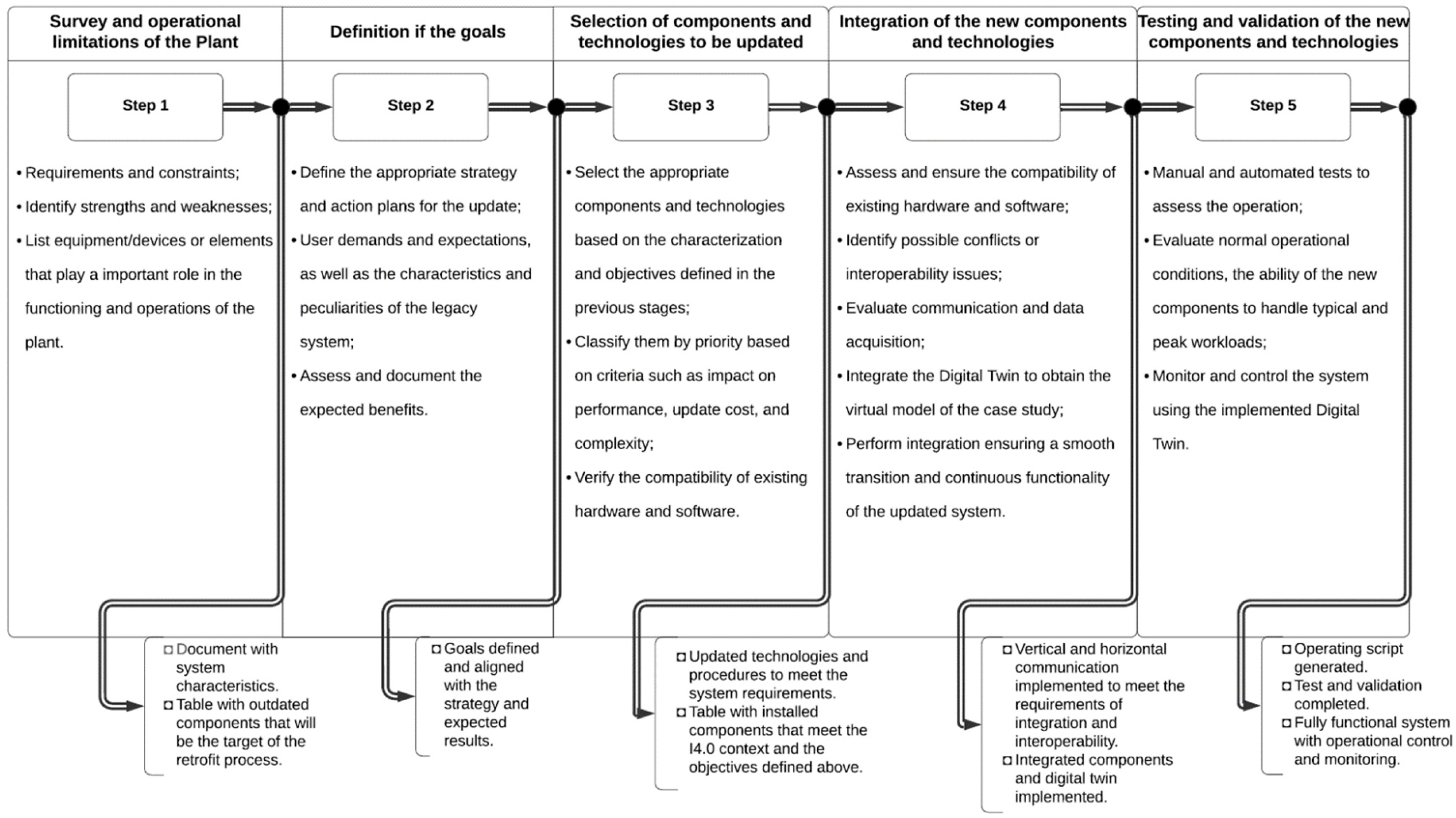
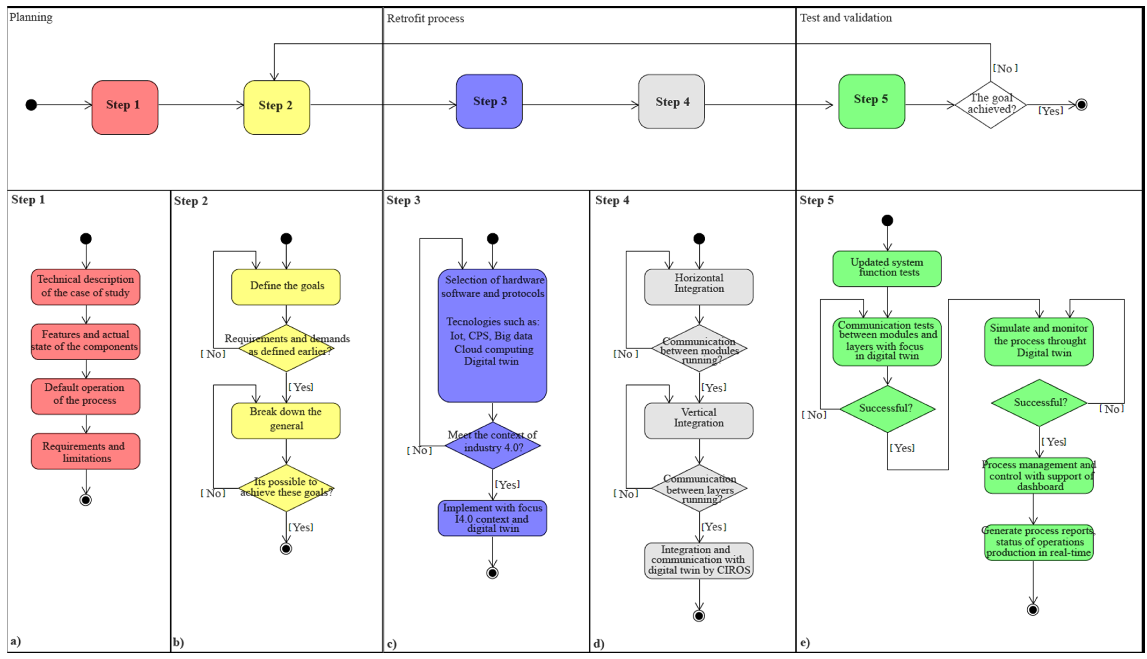
Figure 1 shows a step-by-step implementation of the retrofit process that aims to furnish a systematic and structured approach to updating legacy systems. It involves identifying updated requirements, defining objectives, and making assumptions for development. Consequently, the procedural guide delineates a clear and concise pathway for retrofitting legacy systems. By adhering to the steps outlined, systematic updates can be made to existing systems, ensuring alignment with modern technological requirements. Subsequently, qualitative and quantitative methods are used to evaluate the performance of the updated legacy system.
The goal is to integrate technologies, rendering the legacy system sufficiently and technologically advanced to integrate seamlessly with other processes. Additionally, the system’s maturity is gauged on the basis of the levels of maturity stipulated in the RAMI model, considering its criteria for smart factories [
26].
To update a legacy system by retrofitting techniques, it is necessary to follow a well-defined process to identify and establish update goals that improve efficiency, reduce costs, increase quality, strengthen security, and meet other desirable objectives.
Retrofitting, as described by [
22], is an approach that aims to update existing systems or production processes. The primary purpose is to make them more efficient, flexible, secure, and adaptable to new needs and technologies. This procedure may include adding or replacing devices or technologies and integrating information or management systems as needed.
In parallel, conducting a thorough analysis of the legacy system is essential. This analysis identifies the legacy system’s devices, dependencies, interactions, problems, and limitations. This enables the appropriate selection of technologies to be used in the update. These technologies consider the updated goals as well as the specific characteristics of the legacy system.
During the update process, it is worth defining the devices, procedures, and methods that will be the modification target. Then, tests must be performed to ensure correct functioning, with the necessary adjustments made when problems are identified. Additionally, providing training to users so that they can interact effectively with the implemented changes is essential.
On the basis of the state of the art, the proposed retrofit framework is developed via the following steps to identify problems and consolidate modernization.
Figure 1 presents a general diagram outlining the flow of stages to be applied to achieve the proposed retrofit framework successfully. Each step is detailed in the following section.
2.1. Step 1—Survey and Operational Limitations of the Plant
A detailed analysis of the existing legacy system is essential to ensure successful retrofitting. This involves identifying its strengths and weaknesses, as well as its requirements and constraints.
Figure 2a depicts a diagram outlining the flow of this stage and the expected outcome, considering factors such as evaluating individual components and the technologies that need to be updated or replaced; expected benefits, potential risks, and impacts; cost estimation; and establishing implementation timelines, among others.
Considering all these aspects makes it possible to decide which components to update and how to proceed. This stage is crucial because it provides the foundation for all subsequent steps. Therefore, this stage’s precise and detailed completion is fundamental for a successful updating process, beginning with a thorough understanding of the plant, environment, and installation where the legacy system is deployed. This understanding includes diagrams, schematics, operation flowcharts, and relevant documentation.
Hence, this information identifies equipment, devices, or elements that play a role in the plant’s operational activities. Consequently, these assets may be the primary targets for an update, regardless of the component’s condition (whether it has deteriorated) or the need for an update (if it falls under legacy technology).
2.2. Step 2—Definition of Goals
Defining the appropriate strategy and action plans for the update is essential for identifying the goals for updating the legacy system, including improving efficiency, reducing costs, and increasing flexibility.
Figure 2b shows a diagram outlining the flow of this stage and the expected outcome, emphasizing the identification of the goals and considering user needs and expectations, as well as the characteristics and peculiarities of the legacy system. It is also essential to assess the expected benefits, risks, and impacts, among other aspects.
In addition to defining goals, evaluating and documenting the expected benefits resulting from the successful implementation of the retrofit process is relevant. This may include cost reduction, increased productivity, fewer failures, improved energy efficiency, and sustainability.
Defining solid and realistic goals and mapping the constraints of the legacy system are essential for effectively guiding the retrofitting process. These goals provide a roadmap for project decisions, goal fulfillment, and successful assessment. Therefore, carefully considering the identified needs, evaluating benefits and risks, and mapping the constraints of the legacy system and its impacts helps ensure that the update meets established expectations and quality standards.
2.3. Step 3—Selection of Components and Technologies to Be Updated
Selecting appropriate components and technologies on the basis of the previous characterization and defined goals is essential to ensure a successful updating process.
Figure 2c shows a diagram outlining the flow of this stage and the expected outcome on the basis of the selection of which components or technologies will be updated; their prioritization is based on criteria such as impact on performance, update cost, and installation complexity.
Maintaining a consistent alignment between the decisions made at the initiation stage and throughout the retrofitting process is important. This alignment is essential for ensuring that all actions align with the plant’s requirements. For example, carefully choosing the components and technologies compatible with existing systems can significantly mitigate the integration and operational issues arising from incompatibility. This compatibility ensures a smoother transition during the retrofitting process.
The alignment also allows foresight in technology selection, ensuring that the chosen technologies can be easily updated or expanded. This step is vital for maintaining the system’s relevance and adaptability over time, reducing the need for further extensive retrofits. Therefore, selecting appropriate components and technologies is a fundamental aspect of the retrofitting process. The impact of these choices can significantly influence a project’s overall effectiveness and success.
2.4. Step 4—Integration of New Components and Technologies
Before proceeding with the integration, assessing the compatibility of the new components and technologies with the legacy system is essential. This includes identifying potential conflicts, interoperability issues, and hardware and software requirements. The compatibility of communication protocols is also relevant for ensuring effective communication between systems.
Figure 2d shows a diagram outlining the flow of this stage and the expected outcome.
Therefore, in this stage, it is essential to use a detailed integration plan that outlines the necessary steps to incorporate the new components into the existing system and the sequence of activities, schedules, and procedures for the tests conducted in the next stage.
Integration tests are conducted with careful diligence to establish the appropriate operation of the new components and validate the success of their integration. This procedure involves examining the combined operation of all system components to identify any compatibility issues or communication breakdowns.
These tests are designed to guarantee that each part functions correctly and to ensure that they perform together harmoniously. Any concerns that develop during testing can be resolved quickly, resulting in a smoother transition and lowering the possibility of subsequent operational disruptions.
2.5. Step 5—Testing and Validation of New Components and Technologies
A combination of human and automated tests is an excellent technique for evaluating the capabilities of new components and technologies. Manual tests use a first-hand approach, with functionalities evaluated and confirmed manually, whereas automation tests allow for efficient repetition of usage situations, increasing the overall scope of tests.
As shown in
Figure 2e, this process stage involves conducting specific tests. These tests aim to assess the system under standard operational settings, measure the new components’ ability to manage typical and peak workloads, and determine how well the new components integrate into the old system.
A simulation is used to develop scenarios that assess the performance of new components under various conditions without interfering with the system’s actual operations. This creates a safe setting for identifying and addressing any difficulties.
The testing and validation process is vital for ensuring that improvements to the legacy system are implemented smoothly and that previously specified goals are accomplished. This stage provides a crucial opportunity to detect and resolve issues before they affect regular operations.
This contributes significantly to the continuous integrity and functionality of the modified system. This procedure serves not only as a quality gatekeeper but also as protection for the system’s long-term performance and stability.
2.6. Outlook and Expected Results of the Proposal
A retrofit methodology aims primarily to update and improve legacy systems, bringing them to a more modern context. Continuous monitoring and preventive maintenance become more critical as these systems mature, even when updates are applied. This emphasizes the importance of constant operational monitoring, performing scheduled and corrective maintenance, and replacing components.
The retrofitting procedure is supposed to increase efficiency, as the system benefits from a succession of enhancements caused by the introduction of modern technology and components. These updates can increase processing speed while decreasing processing time and downtime.
Another prediction effect of the retrofitting procedure is enhanced security. Innovative technologies frequently include advanced security features, such as two-factor authentication and data encryption, which add an extra layer of safety to the system.
The retrofitting also increases the system’s flexibility. Recent technology can make the system more adaptable to present and future changes or demands. This adaptability is essential in today’s fast-changing technology environment. Furthermore, the retrofitting process might lead to lower maintenance expenses. New components and technology are frequently easier to maintain and update, resulting in significant long-term cost reductions.
Finally, the five-step process outlines a structured plan for performing a retrofit in a legacy system. This plan guarantees that updates are deployed successfully, preserving the system’s integrity and operation while accomplishing project goals.
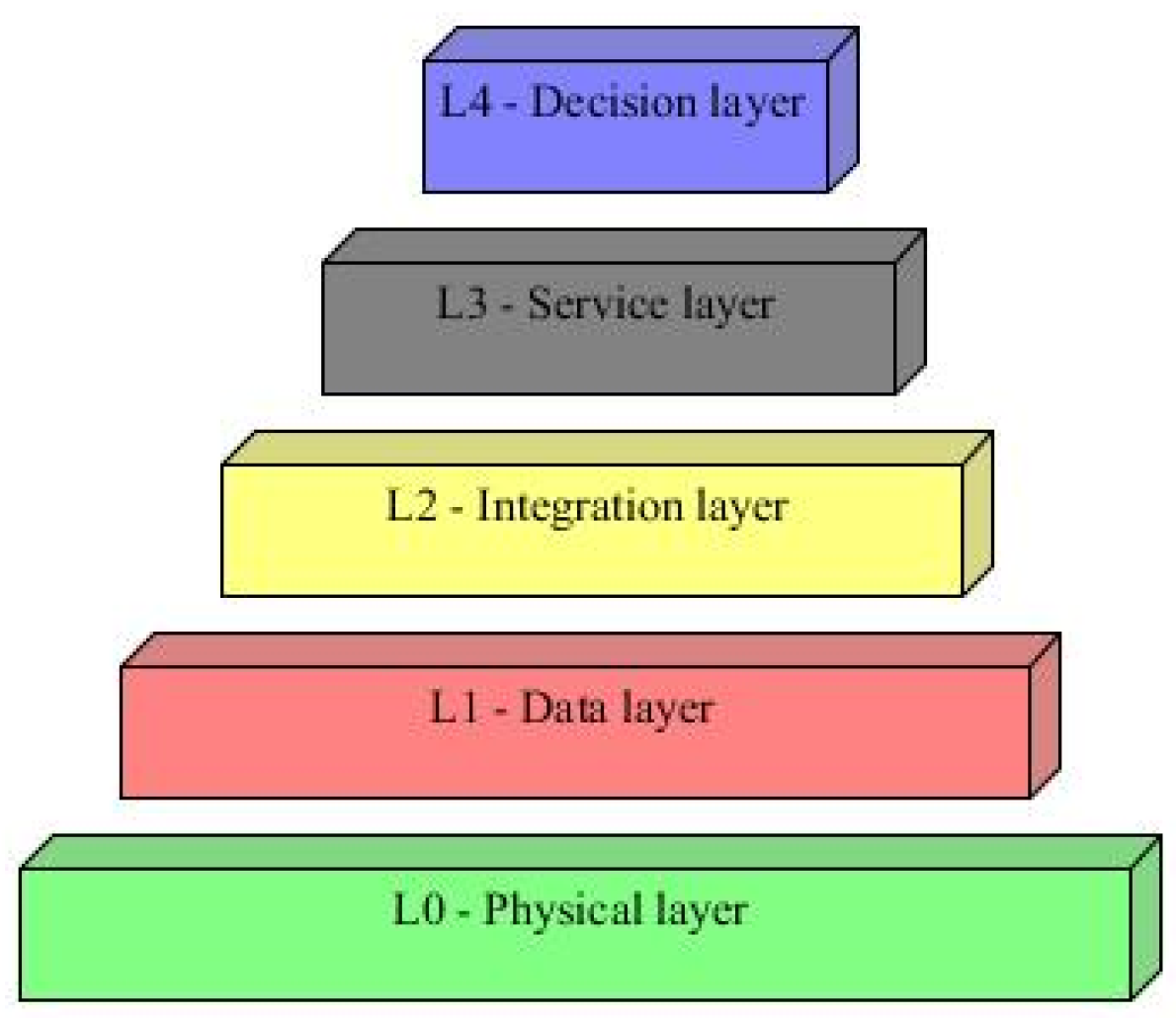
3. Architecture of the Digital Twin
The implementation of this research was based on the proposed architecture inspired by the RAMI 4.0 model presented in previous work by Mendonca [
27]. The architecture was divided into layers, with the DT as the central element of the CPS. Each layer of the proposed architecture is presented in
Figure 3, in order to provide a comprehensive understanding of the structure.
DTs serve as a support, for example, in developing CPSs by providing a unified platform for integrating and managing physical and information systems, enabling simulations and predictions, and optimizing the performance of the process [
28]. The proposed framework provides a structured approach to implementing DT and a global visualization of the interactions between layers and components of the process.
The physical layer (L0) of the proposed architecture includes the physical elements of the CPS. These components include sensors, actuators, conveyors, robotic arms, and pumps. This layer oversees monitoring and collecting data from physical devices.
Horizontal communication protocols such as ProfNet or Modbus make communicating between the many units in this layer easier. The data collected from these devices are sent to the next layer, the data layer, for processing and management.
The data layer (L1) manages the constant data flow from the physical layer. This includes data collected by devices, sensors, and actuators. At this layer, various data-driven methodologies can filter, classify, and organize the data to be processed.
The integration layer (L2) is essential for fluid interactions between layers. It fills the gap between physical and virtual systems. This layer uses various technologies, including the Internet of Things, to effectively link different systems and operations.
The service layer (L3) is essential for developing digital twins (DTs). It utilizes the integration provided by the layer below it (L2) to synchronize with the data and physical layers.
Monitoring, diagnosis and prognosis, verification and validation, fault identification, and management are just some of the services that digital twins can offer. They achieved this by applying data processing, modeling tools, automated reasoning, artificial intelligence (AI), and optimization algorithms.
The decision layer (L4) manages the system’s structure to achieve the defined goals. These aims could involve improving production, minimizing system wear, and reducing production costs. The decision layer can use communication protocols to integrate the system to accomplish these goals vertically.
A critical feature of the decision layer is the ability to utilize a script, which can be created via services such as process monitoring, control, or diagnosis. For example, a digital twin can provide failure prognosis services by evaluating a system device’s remaining life and planning the replacement of devices, sensors, or other process components. This permits maintenance conditions to be changed to reduce costs (minimize losses) and extend the component’s life while ensuring that the process runs continuously.
These five layers offer a structured approach for retrofitting a legacy system. They guarantee that updates are adequately conducted while maintaining the system’s integrity and operation, ensuring project objectives, and completing a retrofit project. This results in considerable system performance, efficiency, and safety improvements, divided by subheadings. It should provide a concise and precise description of the experimental results, their interpretation, and the experimental conclusions that can be drawn.
3.1. Application
The digital twin (DT) can integrate all layers of the proposed architecture, utilizing the capabilities of the cyber-physical system (CPS) to ensure complete control and operation of the entire process [
29]. This is accomplished by modeling the operation on a virtual product life cycle model.
The suggested structure includes a variety of functionalities, each involving a distinct technology. These technologies can be integrated into the system in two ways: vertically or horizontally.
Vertical integration occurs at multiple layers of architecture. It binds the layers together, allowing data and commands to flow seamlessly from top to bottom and vice versa [
30]. For example, vertical integration enables sensors in the physical layer to communicate with applications in the service layer.
Horizontal integration, on the other hand, occurs at a single architectural layer [
31]. It entails creating communication between devices and systems that function simultaneously. Horizontal integration, for example, could involve communication between multiple sensors in the physical layer.
Finally, the proposed structure offers a comprehensive and systematic approach to system integration, allowing for efficient management and operation of all process parts. The result is a more efficient, durable, and intelligent system that can meet the demands of current manufacturing environments.
The connection of the service layer with legacy systems and the specification of how data analysis and simulations are performed via the DT are equally important. To guarantee that the implementation is efficient and effective, all procedures should follow the best practices and standards specified by the proposed design on the basis of RAMI.
The RAMI provides criteria for evaluating and validating outcomes related to the architecture’s implementation and industry maturity level. These criteria permit the evaluation and categorization of the legacy system’s digital transformation and the measurement of the system’s level of Industry 4.0 maturity after the update.
Furthermore, examining the system’s maturity and criteria and validating the use of the retrofitting process enables a realistic evaluation of the results. This technique highlights the modified system’s Industry 4.0 characteristics, allowing for a more precise projection of the acquired result, efficacy, and alignment with the Industry 4.0 environment.
3.2. Maturity Analysis Based on the RAMI Model
The analysis utilizing various criteria is an approach to measure the level of maturity and performance following the Reference Architecture Model for Industries 4.0 (RAMI) [
32]. The RAMI architecture integrates quantitative and qualitative evaluations to evaluate the performance of manufacturing systems [
33].
Quantitative analysis is an objective evaluation that includes quantitative factors such as production volume and time, downtime, and incident reaction time, among others. This consists of production, energy efficiency, and downtime of production systems. The analysis, which is based on numerical measures, aids in measuring the performance of production systems and creating goals. It is typically conducted by analyzing data collected by sensors and information systems. This allows the measurement of key performance metrics such as utilization and production functionality.
In contrast, qualitative analysis is a subjective review that considers qualitative factors such as the quality of components, devices, systems, manufacturing processes, and generated information. Considering that it depends on subjective assessments, it can evaluate more subjective aspects of manufacturing systems, such as flexibility, agility, and product quality. This evaluation can be performed through user interviews, production process observations, and document and report analyses.
In the context of the RAMI architecture, it is desirable to integrate the two studies. This fusion enables a more precise and comprehensive assessment of the Industry 4.0 system or process, which helps optimize decision-making and the manufacturing process. Furthermore, these studies may assist in the planning and execution of updates and improvements.
To determine and categorize the system level, the application technique must be evaluated to ensure that the smart factory criteria are met. The parameters and levels (ranging from 1 to 5)—A higher level represents a closer alignment with Industry 4.0.
The evaluation must be performed simultaneously at the start (to assess the legacy system) and at the end of the methodology application (the updated system). This comparison can be used as a reference to evaluate the improvements that occurred by the update and the system’s current level of maturity in terms of smart factory criteria.
By assessing the maturity level of their production systems, the client may identify areas that require updating and planning the necessary activities to achieve the highest levels of maturity [
34]. This can also help determine the cost-effectiveness of implementing Industry 4.0 technologies. The following criteria are established to evaluate smart factories:
- (1)
Automation of production processes: This evaluates the level of automation in production processes, ranging from data collection to decision-making.
- (2)
System integration evaluates how control systems and data management are integrated, allowing for real-time information interchange.
- (3)
Use of smart devices: This assesses the use of sensors, IoT devices, and other Industry 4.0-enabling technologies.
- (4)
Real-time data analysis: This test determines the system’s capacity to interpret real-time data to aid decision-making.
- (5)
Production flexibility measures a factory’s capacity to react to market demand and production variations.
Understanding the system requires knowing the “before” (legacy system) and “after” (updated system) of this work’s goal and case study, its components, communication, technologies employed, places in the process that can be improved, and categorized as obstacles. The suggested retrofit framework and digital twin architecture provide results that may be analyzed by classifying and comparing the legacy and updated systems.
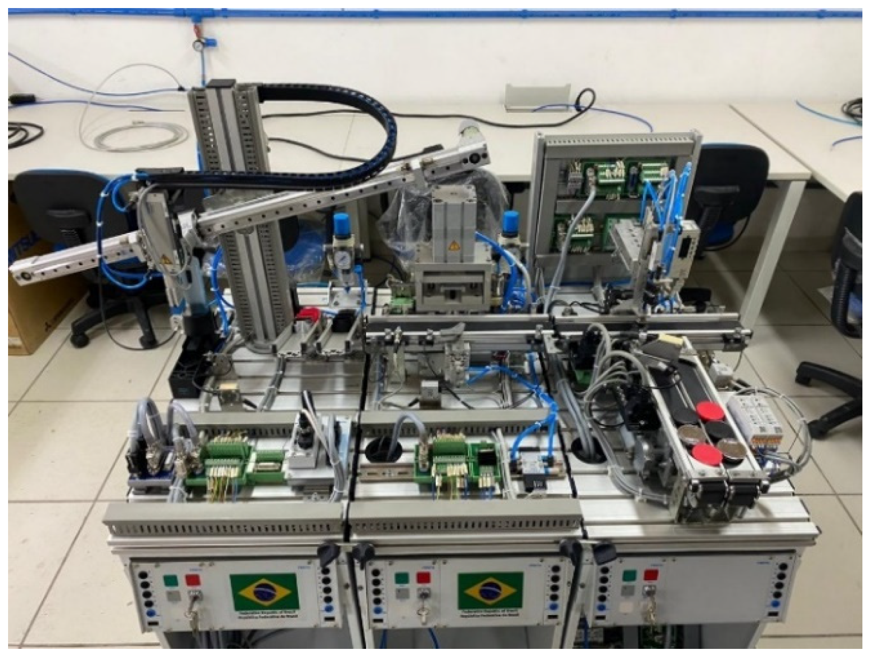
4. Case Study: Application of the Proposed Retrofit Framework in a Didactic Manufacture Production System
The methodology presented can be applied to modernize one or more modules of the Modular Production System (MPS platform). The platform provides a teaching tool for practical education in automation. It is designed to assist teachers and students in understanding the fundamental concepts of automation and to provide practical experience in programming automation systems.
4.1. Brief Description of the Legacy System
The MPS is adaptable and may be used in a wide range of applications, including part production, product assembly, and customized manufacturing. It is organized as a production system divided into modules or autonomous units. These modules can be merged and integrated in line with the individual needs of the manufacturing process.
Each module in the MPS is responsible for a particular stage of the manufacturing process. This could include everything from raw material preparation to component processing and final product assembly. The modular structure of the MPS allows for flexibility, allowing the system to adapt to changing production requirements and conditions.
Default Operation
The system’s input stage can include a variety of containers, including red, black, and metallic containers. Depending on the production script, one or more currencies (resources) are assigned to various containers,
Figure 4 is an example of a running script. These resources may or may not be processed (such as drilling). For example, two coins could be placed in the red container, and a drilled coin could be placed in the black container, but the metallic container may not receive any coins. Red and black containers are essential in this process, whereas metallic containers are discarded.
In module 1 (M1), the containers are placed randomly and individually in the waiting area. A gripper takes up each container and determines whether it is black. The container is carried and placed on the conveyor for the next module if it is. The color information is kept as a variable and sent across the network.
In module 2 (M2), an inductive sensor determines whether the container is metallic. This information is then stored in a variable, indicating the type of container—metallic or red. Depending on the configuration, metallic containers are directed to the disposal site. If a container is red, resources are allotted accordingly, and the module moves on to the next stage as specified in the script.
Module 3 (M3) involves capping the containers. When the type of container is defined, a sensor determines the color of the cap. A suction cup then takes up the cap, shuts the container, and transports it to the waiting point, which connects to the next module.
Module 4 (M4) houses the robotic arm, in which the presence sensor is activated at the end of M3. The gripper picks up the capped container and deposits it on the platform or at the module’s disposal. The robot is programmed to pick up containers and arrange them successively in previously defined locations.
Module 5 (M5) contains a platform that serves as a stock for container processing. This platform comprises six positions organized into two rows and three columns. When all available roles are filled, one option for the production script is to assign additional requests to this module’s discard section.
Finally, as a didactic platform, the system uses hardware (especially a programmable logic controller (PLC)), sensors, actuators, and software to carry out the procedure. This provides a full learning experience that combines theory and practical activities, supported by materials to assist students in understanding and applying principles to real-world problems.
4.2. Results of Retrofit Methodology
When the retrofit methodology was applied to the MPS, the system contained obsolete components and technologies that more current equivalents had since been replaced. This fact confirms the system’s status as a legacy system.
Despite its limits, the system is notable for its adaptability and modularity, which enables the incorporation of new technologies and components. As a result, upgrading the MPS entails updating the outdated system with cutting-edge Industry 4.0 technologies.
The methodical technique for system update (mentioned previously) was followed, and the outcomes for each phase are presented in this section. These findings apply to updating or replacing sensors and equipment to improve efficiency, productivity, system longevity, safety, and product quality. The retrofitting procedure, therefore, revitalizes the legacy system, allowing it to keep up with the improvements of Industry 4.0.
4.2.1. Step 1—Survey and Operational Limitations of the Plant
The MPS platform from Festo was acquired in 2011 and eventually experienced component degradation, sensor misalignment, defects, or failures in actuators and other components, likely due to the effects of time. A complicating factor was that the system remained inactive for an extended period without proper maintenance, leading to further deterioration.
Table 2 shows the components identified in the requirements analysis, which, in the context of Industry 4.0, will be updated.
The Transporter (M1), Press (M2), and Capper (M3) modules are shown in
Figure 4 and have the following characteristics:
Transporter module (Handling—M1)—the gripper’s optical sensor was not correctly fixed, the optical fiber and pneumatic hoses deteriorated or broke, some electrical cables were disconnected, and the entry pneumatic actuator was misaligned. The servo motor was functional, but its control driver had a partial electrical assembly, preventing the transporter from being activated. The controller for this module, the CPX-FEC PLC, was functional even though its control panel was not connected. The other electrical components are in good condition. Thus, the main requirements and limitations were identified, and the necessary activities and modifications to update the module properly for the Industry 4.0 context were determined to achieve the goals.
Press Module (Press—M2)—The pneumatic hoses deteriorated, the pneumatic actuator for the conveyor was misaligned, the press piston was misaligned, and the pneumatic press actuator was misaligned. However, the sensors, controllers, and other electrical components are in good condition.
Capper module (Pick and Place—M3)—pneumatic hoses deteriorate, and some electrical cables are disconnected; one functional conveyor and the other with a torn canvas; the control driver for the functional conveyance is operational; and the positioning sensors are misaligned.
The sensors function correctly. The CPX-FEC PLC was also operational; however, the absence of the control panel was identified. Other components, such as the suction cup and the pneumatic actuator for the z-axis, are worn out; however, elements such as actuators and valves are in good condition and without leaks. The physical situation of this module was more complicated than that of the other modules. Several components must be replaced or reinstalled for proper updates in Industry 4.0.
Robotic Arm Module (Robot—M4) integrates the platform with the stock. This module is not functional and has lost its home position. Owing to the system being turned off for an extended period, the hoses deteriorated, and some electrical cables disconnected. The arm axes need lubrication, and the home and initial state points need recalibration.
Similarly, after a brief test, it was observed that the robot controller turns on but does not initialize. The controller display does not light up, and on Teach Pendant, only the initialization warning is signaled with an error code on the screen. There is also a Parts Storage Module (M5), which is used to allocate finished and discarded containers in the MPS platform process and is in good condition.
4.2.2. Default Operation
The proposed retrofit framework for the MPS platform is designed to restore, update, and connect the system with other devices. This enables synchronization with the Industry 4.0 framework, particularly with respect to technology that supports the digital twin concept.
This technique is advantageous in an academic setting, as it introduces and combines concepts essential to Industry 4.0. It is a platform for simulating and developing new and existing operational proposals. Furthermore, it enables improvements and alterations to the process structure, as well as the commissioning of all stages.
The main focus of the MPS platform’s hardware update is the replacement of physical components, electrical and pneumatic connectors, and the updating of old technologies. The particular goals of this hardware update are discussed in the following sections.
The main focus of the MPS platform’s hardware update is the replacement of physical components, electrical and pneumatic connectors, and updating outdated technologies. The particular goals of this hardware update are discussed in the following sections. The MPS platform is updated with current concepts, and by undergoing this update, its usability and performance are improved following Industry 4.0 requirements. The following are the detailed goals:
Cleaning and sanitizing modules and components;
Organization of electrical connectors;
Replacement of all pneumatic hoses;
Mechanical alignment of the conveyors in all modules;
Calibration and testing of the pneumatic actuators in the modules;
Replacement of module controllers with updated controllers;
Replacement and installation of the optical sensor fiber in M1;
The installation of a new motor and its respective driver in M1;
Installation of a new acrylic protection in M2;
Lubrication and calibration of the pneumatic actuator that inserts coins in M2;
Replacement of the suction cup plunger for the caps in M3;
Replacement of the belts on the conveyors in M3;
Installation of the physical control panel for the module in M3.
4.2.3. Step 3—Selection of Components and Technologies to Be Updated
The retrofitting process provides improved ease of use and configuration, the introduction of new functionalities, and the correction of any process concerns via web monitoring.
Figure 5 illustrates the comprehensive approach to the MPS platform.
Table 3 shows that the new controller CPX-CEC-C1-V3 was installed during the hardware updates. This controller was explicitly built to control process systems. It is a small, high-performance device that combines automation operations, communication, and a human–machine interface in one device. A high-speed microprocessor powers it and has a variety of communication interfaces, including CANopen and USB.
This controller has an intuitive user interface that allows straightforward process setting and monitoring. Its communication interfaces enable users to control various automation devices, including actuators and sensors. It is also used to monitor the status of devices and manage alarms and error messages. Programming tools that comply with IEC 61131-3 standards enable users to program and adjust the system’s automated functionalities efficiently [
35].
The CANopen network enables real-time monitoring and control of platform operations and configuration and programming of various devices and modules. It provides a secure and effective method for ensuring communication between different elements of a smart factory and enables the integration of multiple automation systems. The updated MPS can function with increased communication and control owing to the CANopen network, which aligns with Industry 4.0 requirements.
4.2.4. Step 4—Integration of New Components and Technologies
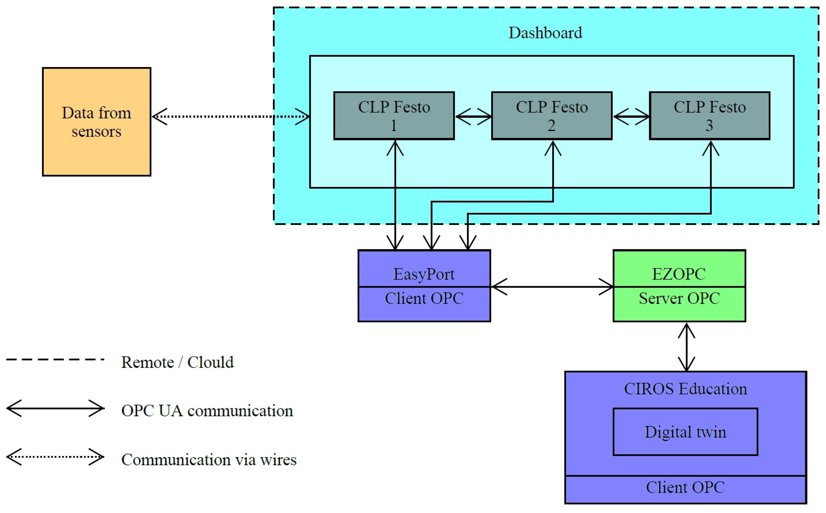
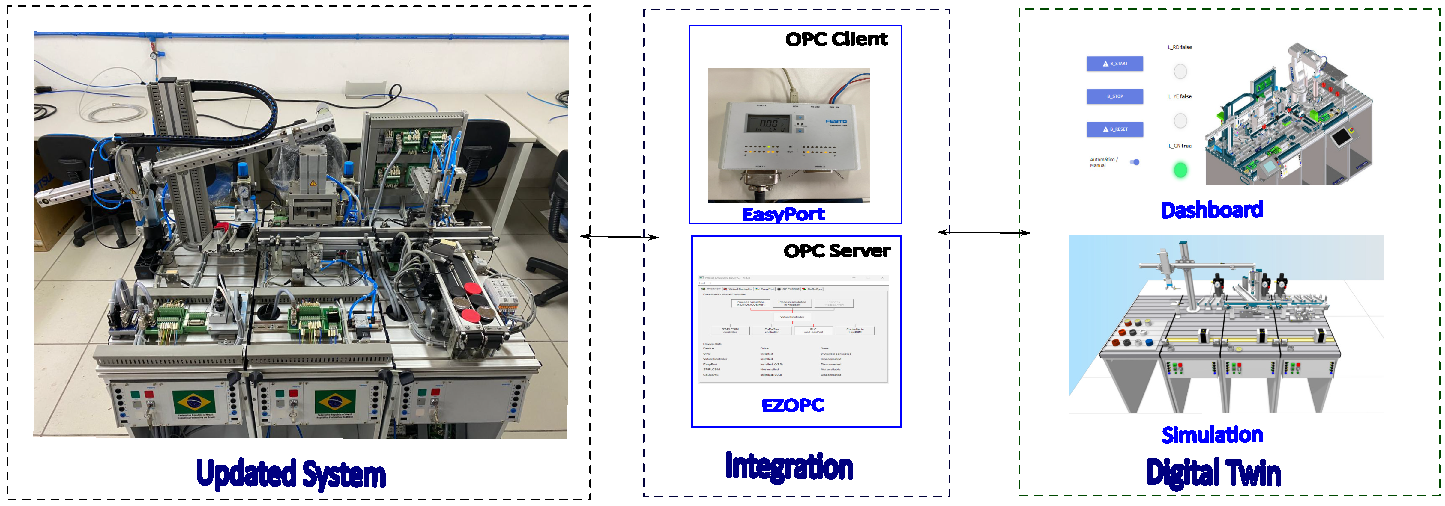
This phase involves the integration and commissioning of new components and technology. This requires guaranteeing that these components are appropriately incorporated into the existing system. The implementation was completed to generate a digital twin.
An approach for connecting devices to a computer network via EasyPort was established. EasyPort is an interface allowing MPS platform modules to communicate via a USB connection with a computer. This interface provides various tools for configuring and monitoring the sensors and actuators involved. It is interoperable with multiple Festo components, including cylinders, valves, sensors, and actuators, on the MPS platform. It is a gateway that connects one or more platform modules to the application, in this case, CIROS, where the digital twin was developed.
In CIROS Education, the computer’s digital twin was implemented to model, test, and train the skills required for industrial production. Thus, the representation of the operation (virtual twin) of the MPS platform is implemented in the CIROS. It reveals features that provide real-time data monitoring, event logging, and remote diagnostics. This reproduction mirrors what is happening on the MPS platform (physical twin), the state of sensors and actuators, and the process status.
Figure 6 shows how the physical twin’s operation is replicated and synchronized with its virtual twin.
Figure 6 shows the running of the production scripts, where it is possible to observe the synchronization between the virtual twin and the physical twin. In
Figure 6A, we see the beginning of the process in M1, where the piece is inserted and we identify if it is black. Next, the conveyor picks up this piece and places it on conveyor 2. This stage is fully synchronized, as the virtual twin reads the physical inputs and outputs, keeping them aligned with the virtual inputs and outputs.
In
Figure 6B, which functions as a simulation, we represent the stage where the part arrives at M2, where the process continues normally with the identification of whether the part is metallic, the addition of resources, the pressing, and finally, the forwarding to M3.
Figure 6C illustrates the picking place process, also in simulation format, where the containers are capped according to color and then sent for storage. It is important to highlight that the digital twin was applied only in M1, that is, in the handling phase. In the other modules, the inputs and outputs are exclusively physical, without synchronization with the virtual inputs and outputs, due to the need for an EasyPort module with CanOpen for each of the PLCs.
Figure 7 shows that communication occurs via EasyPort and EZOPC, a connectivity interface that facilitates communication between Festo’s automation equipment. EZOPC 5.4 is a software tool that enables the communication and control of Festo components through an OPC (OLE for Process Control) connection, a widely used communication standard in the automation industry. OPC enables different control systems and devices to communicate effectively with each other.
In this configuration, the CIROS operates as an OPC client. It communicates with EZOPC, the OPC server, via the OPC protocol. EZOPC, in turn, connects to EasyPort, another OPC client. This layered communication ensures that other systems can be successful. Monitor and control data from the MPS platform’s sensors and actuators. The data are collected and transmitted via EasyPort to the digital twin program, which simulates and monitors the MPS platform’s physical processes.
The integration and commissioning phases ensure that all new components and technologies are smoothly integrated into the system. The system is rigorously validated and tested throughout these phases to improve its modeling, control, and data analysis capabilities. EasyPort and CIROS Education are used to construct a digital twin that simulates the physical processes of the MPS platform in a virtual environment. This complete strategy ensures that the system functions safely, efficiently, and reliably.
4.2.5. Step 5—Integration of New Components and Technologies
This step involves performing the production script and meticulously reviewing the system’s performance, emphasizing the operation of actuators and sensors. These components are necessary for accurate MPS platform operation since they directly impact manufacturing process control and monitoring. Furthermore, finishing and inspection tests are conducted to guarantee that the system satisfies all the set quality standards.
Ensuring that all basic needs have been met during this phase is essential. Any irregularities discovered must be corrected immediately. This may require revisiting the first steps (Steps 1 and 2) and reopening the procedure to ensure complete integration and functionality. After making the necessary changes, the conformity of the new components and technologies may be validated, ensuring the system’s safety, efficiency, and dependability.
The system was assessed through activation tests and operational cycles. These tests were created to ensure that the system performs optimally under various scenarios.
Figure 8 shows that the proposed retrofit architecture was effective when it was applied to the MPS platform case study. The diagram depicts an intuitive interface for monitoring, configuring, and controlling processes in the physical twin.
The digital twin accurately duplicated the real-time activities of the MPS platform during testing. This involved monitoring actuator runtimes and detecting delays in the process, such as the pressing module, which took longer to accomplish jobs than other modules did. The fundamental purpose of the digital twin was to replicate and control processes in real time. This functionality enables interaction, pausing, and restarting of process parameters, allowing detailed studies to assess the impact of changes and foresee probable undesirable situations in the MPS platform.
The proposed retrofit framework was verified by examining the smart factory’s maturity level and product specifications. This complete method ensures that the system operates with maximum safety, efficiency, and dependability. The extensive analysis and validation processes play an essential role in determining whether integrating new components and technologies improves the overall performance and reliability of the MPS platform.
The system’s actuators and sensors are checked to ensure that they fulfill quality standards by running the production script and performing detailed assessments. Addressing anomalies and certifying the system via activation tests and operational cycles ensures peak performance. The digital twin’s capacity to mimic and control operations in real time expands the system’s capabilities, making it a reliable solution for current production environments.
5. Discussion of Maturity Level Analysis Considering the Smart Factory Criteria
The maturity level of the MPS platform can be assessed to determine its alignment with Industry 4.0 technologies and practices. This study thoroughly reviews the system’s features as a legacy system and after retrofitting. The primary goal was for the improved MPS platform to perform significantly better than the legacy system in the RAMI maturity assessment. This includes evaluating the maturity criteria for smart factories.
Each criterion’s characteristics and degree of development were evaluated to classify the MPS platform on the basis of the smart factory and smart product maturity levels. The requirements for smart factories (F1–F5) were thoroughly assessed. This evaluation allowed us to establish a reasonable classification for each parameter level.
This work contributes by evaluating and applying Industry 4.0 maturity levels and criteria. It is used to validate the suggested retrofit framework for the digital twin, which has been created throughout this research. The framework was guided by information gained from the initial review of the legacy system, which impacted the choice of components and technologies. This method resulted in a greater degree of development for each measured metric.
Table 4 compares the legacy and updated systems using smart factory criteria. The legacy system provided parameter F1, a level 3 based on the “good” level of automation achieved with electrical and pneumatic components. However, F2 was rated as level 2 because the MPS platform’s integration was restricted by legacy architecture and interoperability problems.
The previous system parameters F3, F4, and F5 were classed as level 1 because no intelligent devices were installed or had any data analysis or processing capacity. The manufacturing method lacks flexibility due to intrinsic restrictions.
Following the update process, the findings revealed considerable improvements. Parameters F1, F2, and F4 achieved level 4, meeting the requirements for enhanced automation, real-time process monitoring and control, increased integration, and efficient data gathering and processing capabilities. Parameters F3 and F5 reached level 3, indicating progress in process component improvements, flexibility, integration, and the ability to simulate various production scenarios.
The spider web graphic in
Figure 9 demonstrates the success of the proposed retrofit architecture for digital twins. The illustration depicts significant improvements in the manufacturing process, including better real-time data collection and analysis, informed decision-making, and the identification of process concerns. Additionally, platform components’ communication and connections were improved, making them more versatile and robust.
The system’s alignment with Industry 4.0 technologies and processes was greatly improved by studying and improving the maturity level of the MPS platform. The examination and application of the Industry 4.0 criteria confirmed the suggested retrofit framework, resulting in significant gains in automation, integration, and data processing capabilities. The successful adoption of the digital twin highlighted the system’s improved performance, flexibility, and dependability.
6. Conclusions
The proposed retrofit framework was applied to the MPS platform to generate a digital twin, and the updated process improved significantly. Updates and replacements of sensors and devices on the MPS platform followed the defined systematic procedure, bringing the system up to Industry 4.0 requirements. This update has various advantages, including a longer lifespan, improved integration, flexibility, etc.
The evaluation of the MPS platform’s maturity level, which is based on the RAMI characteristics for smart factories, revealed considerable improvement from the legacy to the updated system. The goal of a higher position in the maturity evaluation demonstrates the dedication to aligning the MPS platform with the most recent industry trends and practices.
The most notable contribution of this work is the effective implementation of the retrofit framework aimed at the digital twin. The validation of the technique by evaluating the Industry 4.0 maturity level emphasizes the need for retrofitting and aligning modernization practices with evolving industry demands. This technique verifies the retrofit architecture and emphasizes the strategic value of updating legacy systems to meet modern requirements.
The table and spider web charts compare the legacy and updated systems, which support the success of retrofitting. The investigation revealed significant gains in critical areas, including real-time data gathering and analysis, informed decision-making, process integration and interoperability, and improved communication among platform components. Communication and simulation tools such as CANOpen, EasyPort, EZOPC, and CIROS were essential to the update process, allowing for more efficient integration and matching of the basic methodology requirements.


 ,
, 


