Article

Numerical Investigation of Heat Transfer Characteristics of Trapezoidal Fin Phase Change Thermal Energy Storage Unit

1
School of Resources & Environment, Nanchang University, Nanchang 330031, China
2
School of Advanced Manufacturing, Nanchang University, Nanchang 330031, China
*
Authors to whom correspondence should be addressed.
Processes 2024, 12(6), 1080; https://doi.org/10.3390/pr12061080
Submission received: 12 April 2024 / Revised: 17 May 2024 / Accepted: 22 May 2024 / Published: 24 May 2024

Abstract

:
In order to enhance the heat transfer performance of a phase change thermal energy storage unit, the effects of trapezoidal fins of different sizes and arrangement modes were studied by numerical simulation in the heat storage and release processes. The optimal enhancement solution was obtained by comparing the temperature distribution, instantaneous liquid-phase ratio, solid–liquid phase diagram and comprehensive heat storage and release performance of the thermal energy storage unit under different fin sizes. During the heat storage process, the results show that when the ratio of the length of the upper and lower base of the trapezoid h1/h2 is 1:9, the heat storage time is shortened by 9.03% and 18.21% compared with h1/h2 = 3:7 and 5:5, respectively. During the heat release process, the optimal heat transfer effect is achieved when h1/h2 = 5:5. To further improve the heat transfer effects, the energy storage unit is placed upside down; then, the least time is achieved when h1/h2 = 2:8. When heat storage and release are considered together, the energy storage unit with h1/h2 = 2:8 takes the shortest time to melt in upright placement and then to solidify in upside-down placement.

1. Introduction

With the vigorous development of new energy, phase change heat storage technology has been widely applied in the development of sustainable energy because it offers stable energy storage [1,2,3], small device volume [4,5,6,7], and broad temperature adaptability [8,9]. However, the thermal conductivity of phase change materials (PCMs) is usually low; scholars have improved the heat transfer performance of thermal energy storage units (TESUs) by modifying the structure of the energy storage devices [10].
The influence of the angle variation of longitudinal fins connected to horizontal pipes on the melting and solidification characteristics of PCMs was considered by Yuan et al. [11]. The numerical study conducted by Wang et al. [12] shows that, if the spacing between fins is four times greater than the inner radius of the pipe, the influence of the fin radius on the heat storage efficiency is not significant. The influence of fin parameters (number of fins, height, and thickness) was studied by Yang et al. [13]. The optimized parameters for minimizing the melting time of PCMs around vertical finned tubes were determined to be as follows: a fin number of 31, a ratio of fin thickness to pipe length of 0.0248, and a ratio of fin spacing to pipe length of 0.0313. The numerical model of three-dimensional Y-shaped and T-shaped fractal fins for phase change TESUs, studying the effects of fractal fins and inlet fluid temperature on the heat storage/release process, was established by Ren et al. [14]. Upside-down oriented finned tube TESUs were studied by Zhang et al. [15] while discussing the effects of heat conduction, thermal convection, and secondary flow on the performance of the thermal storage unit. Research has shown that heat conduction is the primary mode of heat transfer in smooth tubes, while natural convection leads to uneven melting vertically. Furthermore, secondary flow has a significant influence on the heat transfer process of the TESU. The promoting effect of individual helical fins was studied by Zonouzi and Dadvar [16]. The enhancement effects of inclined fins on shell-and-tube TESUs, including different angles of inclination and structural designs of fins, were investigated by Guo et al. [17,18]. The enhanced heat transfer effects of longitudinal fins in horizontal shell-and-tube thermal storage devices were investigated by Yang et al. [19]. The results indicate that adding fins enhances heat storage efficiency, and increasing the number of fins also improves energy storage efficiency, however, it reduces localized natural convection within the storage unit. The heat transfer performance of double-tube (DT), triplex-tube (TT), and multi-tube (MT) units was investigated by Janusz T. Cieśliński et al. [20]. The melting process of latent heat thermal energy storage with fins of various irregular shapes and sizes was improved by Farqad T. Najim et al. [21].
In summary, scholars have extensively explored fin-enhanced heat storage enhancement technologies through a combination of experimental and numerical simulation methodologies. Studies indicate that the trapezoidal structure of fins accelerates the melting of PCMs near the outlet and reduces the temperature difference across the entire TESU, enhancing the energy storage efficiency of the storage unit without altering the heat transfer area. Nonetheless, research focusing on trapezoidal fins remains notably scarce in the literature. This study employs numerical simulation to investigate the influence of structural parameters and placement strategies of axial trapezoidal fins on the heat transfer characteristics of phase change TESUs, utilizing paraffin as the PCM. The primary aim of this research is to provide valuable insights aimed at improving the energy storage efficiency of heat storage systems.

2. Materials and Methods
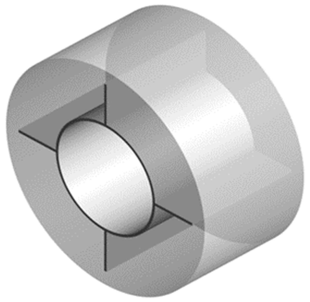
2.1. Physical Model

The different distribution of heat along the axial direction in shell-and-tube phase change heat storage systems results in uneven melting of the PCM within the storage unit. In order to accelerate the melting of PCM near the outlet and reduce the temperature difference across the entire TESU, a trapezoidal structure of fins varying along the axial direction was designed. This design aims to enhance the energy storage efficiency of the unit while keeping the heat transfer area unchanged. Figure 1 shows the structural sketch of the model. In the model, the inner tube is a copper pipe with a diameter of 18 mm and a wall thickness of 1 mm. There are four longitudinal trapezoidal fins made of copper distributed along the circumference of the outer wall of the inner tube, and the outer tube radius R is 50 mm. The height of the model, D, is 100 mm. Considering the computational workload and the symmetric nature of the TESU, one quarter of the entire structure was selected as the computational domain. Water is used as the heat transfer fluid (HTF). This study found that the flow direction has a very weak influence on the heat transfer performance; thus, the HTF is set to circulate from top to bottom as shown in Figure 1b, which is applied to all simulations in this study. The structural design of the trapezoidal fins depends on the location of the heat transfer deterioration zone. Due to natural convection, during the melting process, the hard-to-melt zone is at the bottom, while during the solidification process, the hard-to-solidify zone is at the top. Therefore, the fin structures should be tailored according to specific circumstances.

2.2. Mathematical Model

Using the enthalpy-porosity method, the melting process of PCM was simulated based on discrete computations on a fixed grid. The commercial program ANSYS FLUENT 2022 R1 from ANSYS, Inc., San Diego, CA, USA was used in this study. As PCM melts, the porosity of the porous region increases from 0 (solid) to 1 (liquid). The liquid PCM in the cavities is treated as a Newtonian incompressible fluid. Viscous dissipation of the liquid is neglected, and there is no contact thermal resistance between the fins and the wall surfaces. Based on these assumptions, the governing equations for PCM are as follows:
The continuity equation is
ρ t + · ρ U = 0
The momentum equation is
t ρ U + · ρ U U = P + ρ β P C M g T T m + 1 L L 3 + δ A m u s h U
where, U represents velocities in the x, y, z directions, (m/s), ρ represents density of PCM, (kg/m3), βPCM represents thermal expansion coefficient of PCM, g represents gravitational acceleration, (m/s2), T represents temperature of PCM, Tm represents melting temperature of PCM, (K), Amush represents constant of the mushy zone, (105 kg/m3s) [22,23], L represents the liquid portion within TESU, defined as
L = 0 i f   T < T s L = T T s T l T s i f   T s < T < T l L = 1 i f   T T l
where, Ts represents solidus temperature of PCM, Tl represents liquids temperature of PCM.
The energy equation is
ρ H t + ρ U H = · k T
where, H represents total enthalpy of PCM, (J), k represents thermal conductivity of PCM, [W/(m∙K)], the total enthalpy of the material can be defined as the sum of latent heat ΔH and sensible heat h
h = h r e f + T r e f T c p d T H = h + Δ H
where, Tref represents reference temperature, (K), href represents reference enthalpy of PCM at reference temperature, (J), ΔH represents the latent heat value in kJ/kg, ranging from 0 (solid PCM) to Q (liquid PCM), and Q represents latent heat of PCM from solid to liquid.
Δ H = L Q

2.3. Boundary Conditions and Computational Settings

In this study, paraffin serves as the PCM, with the fins made of copper. Water is used as HTF in the numerical simulation. The physical properties of the materials are shown in Table 1. The water inlet temperature is 353.15 K, with a mass flow rate of 0.01109x kg/s (equivalent to a volumetric flow rate of 40 L/h). The initial temperature of the PCM during the melting process is 288 K, with a free outflow outlet. For the solidification process, the initial temperature of PCM is 353.15 K, the water inlet temperature is 288 K, and the mass flow rate inlet is 0.01109 kg/s (equivalent to a volumetric flow rate of 40 L/h), with a free outflow outlet. The outer tube wall and both end faces are adiabatic.
Double precision computation is employed. The pressure-velocity coupling adopts the SIMPLE (Semi-Implicit Method for Pressure-Linked Equations) algorithm, which uses the mutual correction relationship between pressure and velocity to enforce mass conservation and obtain the pressure field, and the pressure differences are calculated by the PRESTO (Pressure Staggering Option) scheme, which uses the discrete continuity balance for a staggered control volume about the face to compute the staggered pressure. The energy and momentum equations are numerically computed using the fast difference method and second-order implicit transient method, respectively. The convergence residual values for the continuity equation, momentum equation, and energy equation are set to 10−4, 10−4 and 10−6, respectively. The maximum number of iterations within each time step is set to 500.

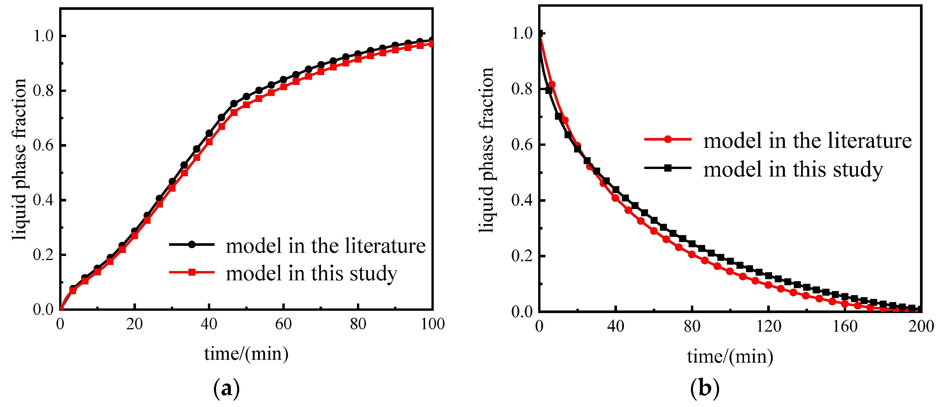
2.4. Mesh Independence and Model Validation

To ensure the accuracy of the calculations, the influence of grid size and time step on the research results needs to be accounted for. Therefore, this study compares calculations using five different grid densities (96,652, 153,788, 244,300, 375,868, and 667,000 grids) for the model structure with h1/h2 = 1:9, as well as five different time steps (1.0 s, 0.5 s, 0.2 s, 0.1 s, and 0.01 s) as shown in Figure 2. After considering both the computational workload and accuracy, a grid count of 244,300 and a time step of 0.1 s were selected.
Figure 3 shows the physical model from Ref. [24], which is used to validate our simulation method in this study. This PCM latent heat thermal energy storage system is composed of cylindrical annuluses with fins, and RT82 is used as the PCM. The initial temperatures of the melting and solidification processes are 300.15 K and 363.15 K, respectively, and the temperatures of the inner tube for melting and solidification processes are 363.15 K and 338.15 K, respectively. The evolution of the liquid phase fraction over time during the melting and solidification processes is presented in Figure 4. By comparison, it is evident that the trends in the evolution of the liquid phase fraction over time are consistent with the literature, and the maximum error in the experiment does not exceed 3%, thus providing sufficient evidence for the reliability of the numerical model and methodology in this study.

3. Results and Discussion

This study investigated the melting and solidification characteristics of PCM within TESU. Additionally, it explored the influence of different ratios of trapezoidal fins’ upper and lower bases (h1/h2 = 1:9, 3:7, and 5:5) and the orientation (upright and upside-down) of the TESU on their phase change processes.

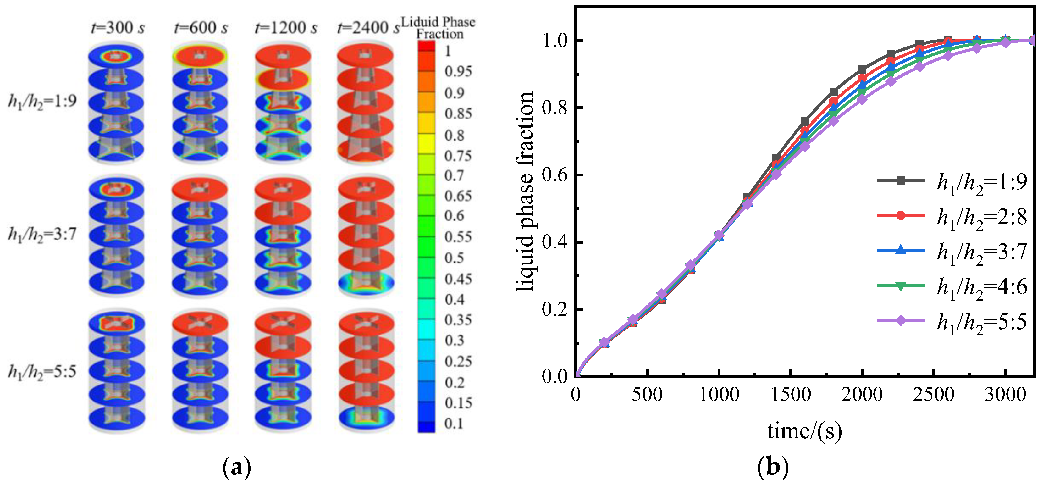
3.1. Melting Process

Figure 5a presents the phase diagrams of solid–liquid distribution for the TESU with three different fin structure sizes (h1/h2 = 1:9, 3:7, and 5:5) at different time points. Meanwhile, Figure 5b depicts the instantaneous liquid phase fractions inside the TESU with five different fin sizes (h1/h2 = 1:9, 2:8, 3:7, 4:6, and 5:5).
In Figure 5a, at t = 300 s, the melting rate of h1/h2 = 5:5 surpasses the others, exhibiting a contour resembling a quadrilateral, influenced by the fins. At this point, the instantaneous liquid phase fraction of h1/h2 = 5:5 exceeds that of h1/h2 = 1:9 and h1/h2 = 3:7 by 5.71% and 2.80%, respectively. By t = 600 s, the top PCM melting rate of the h1/h2 = 1:9 structure remains relatively slow. By t = 1200 s, the top PCM of all three TESUs has nearly entirely melted, albeit with the h1/h2 = 1:9 unit retaining a small amount of unmelted PCM. Particularly notable is at t = 2400 s, where the instantaneous liquid phase fraction of h1/h2 = 1:9 reaches 98.86%, exceeding the other structures by 3.92% and 3.52%, respectively. This is attributed to the larger area of lower fins in the h1/h2 = 1:9 unit, enhancing heat transfer and accelerating the melting rate. At this moment, only 4.14% of PCM remains incompletely phase changed in the h1/h2 = 3:7 unit, while the h1/h2 = 5:5 structure retains 7.84%.
In summary, characterized by shorter fins near the inlet, the TESU with fin dimensions of h1/h2 = 1:9 exhibits a slower initial melting rate. However, accelerated melting of PCM in the middle and lower sections is facilitated by the larger area of fins. As a result, this structure completes the melting process the fastest, taking a total of 2568 s.

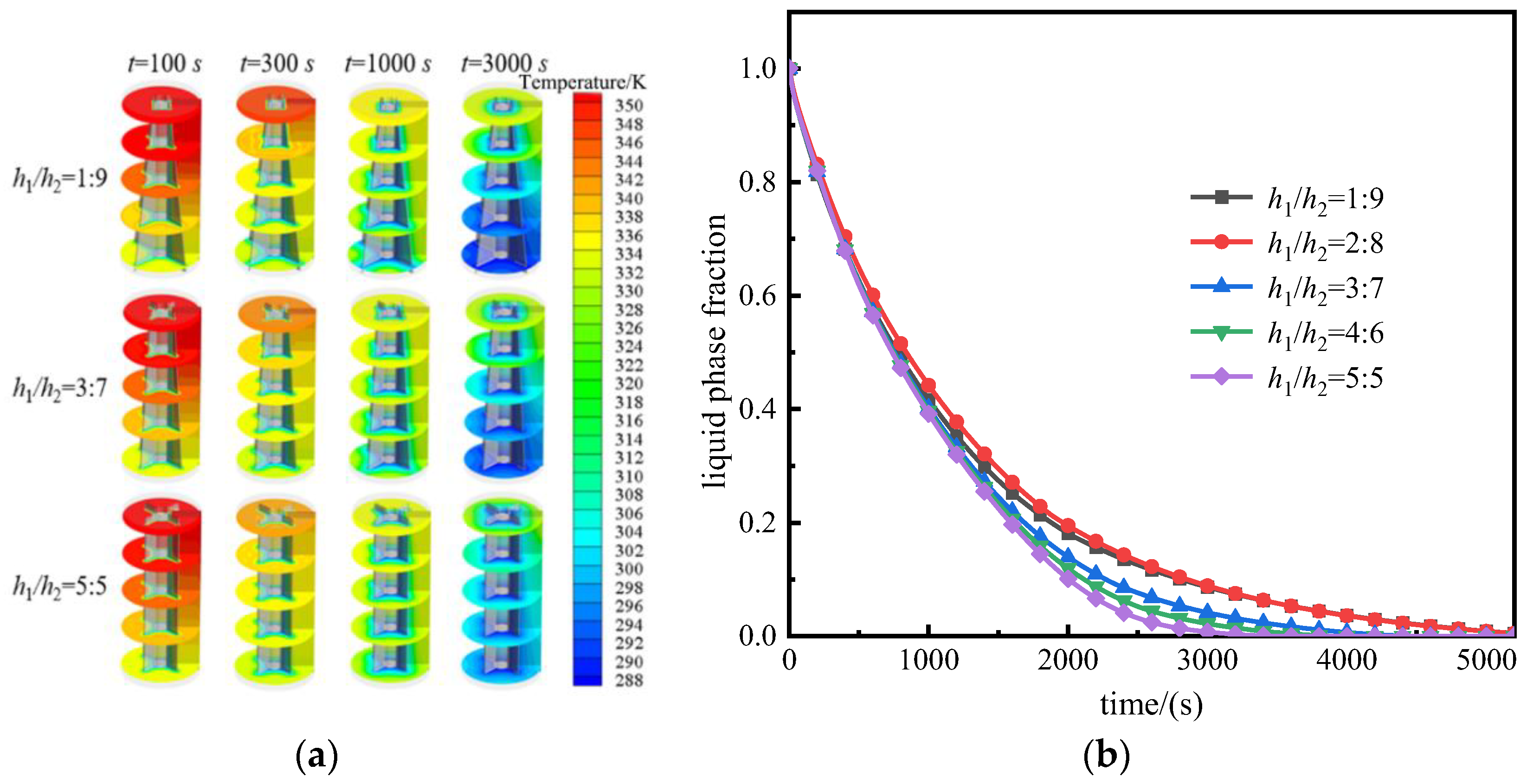
3.2. Solidification Process

3.2.1. Upright Placement of TESU

Figure 6 shows the temperature distribution at various time points for TESUs with different fin sizes when uprightly placed in the solidification process. At t = 100 s, the temperature distribution for TESUs with different fin sizes is similar, and the instantaneous liquid phase fraction for each structure is around 90%. By t = 300 s, the h1/h2 = 1:9 structure exhibits the highest temperature at the top, with a temperature of 347 K on the first cross-section, while the h1/h2 = 3:7 and h1/h2 = 5:5 structures have a maximum temperature of approximately 343 K on the first cross-section. This is due to the h1/h2 = 1:9 structure having fewer fin extensions near the inlet, leading to an increased heat transfer distance. Simultaneously, the upward movement of heat causes heat accumulation at the top of the structure. The average temperature for all three TESUs is around 330 K, and the liquid phase fraction for each is around 74%.
At t = 1000 s, the temperature difference between the top of the TESU with h1/h2 = 1:9 and those with h1/h2 = 3:7 and 5:5 structures is relatively small. However, the maximum temperature difference at the bottom can reach up to 5 K. This is because the influence of fin dimensions near the inlet on the solidification process gradually decreases with time, while the material properties of PCM gradually become the primary influencing factors. Therefore, the maximum temperature difference at the upper part of the structures gradually decreases. In the lower part of the TESU, the solidification rate of PCM is mainly determined by the size of the heat transfer area. The h1/h2 = 1:9 structure has a larger heat transfer area in the lower part, resulting in a faster heat exchange rate. Consequently, the maximum temperature at the bottom of the TESU with this size is significantly lower than that of the other structures. In terms of average temperature, the TESU with h1/h2 = 1:9 has an average temperature of 332 K at the first cross-section, while the unit with h1/h2 = 5:5 has a temperature of 327 K at the same cross-section. Moreover, the former has an average temperature of 307 K at the fifth cross-section compared to approximately 314 K for the latter.
When the fin structure is h1/h2 = 1:9, the temperature difference in the lower part of the TESU increases, accelerating the solidification of PCM. Additionally, when the fin structure is h1/h2 = 5:5, the temperature difference in the upper part of the TESU increases, also promoting solidification. Comparing with Figure 6b, it can be observed that the liquid phase fraction of the TESU with h1/h2 = 1:9 is the largest among the three, reaching 41.68%. This phenomenon is still observable at 3000 s, but at this time, the overall average temperature of the TESU is lower when the structure is h1/h2 = 5:5, at 302 K. Comparing the instantaneous liquid phase fractions in Figure 6b, it can be found that the TESU with h1/h2 = 5:5 completes the solidification process the fastest, taking only 3595 s, which is 37.64% shorter than the time required for the TESU with h1/h2 = 1:9. The TESU with h1/h2 = 2:8 takes the longest time to solidify, totaling 5830 s, which is 62.17% longer than the solidification time of the TESU with h1/h2 = 5:5, and the TESU with h1/h2 = 2:8 has the most liquid phase fraction throughout the entire solidification process. Compared with the TESU with h1/h2 = 1:9, although the TESU with h1/h2 = 2:8 has a better promotion effect in the upper part of the structure, the latter has a better enhancement effect on the lower part of the TESU. In summary, the TESU with h1/h2 = 1:9 slightly outperforms in the solidification process, with an improvement of about 1%.

3.2.2. Upside-Down Placement of TESU

Due to the effect of gravity, heat tends to accumulate at the top of the TESU. Placing the TESU upside down increases the heat transfer area at the top, facilitating the timely dissipation of accumulated heat and the solidification of the PCM in the top region.
Figure 7a shows temperature distributions at different time points for the upside-down placed TESU, while Figure 7b illustrates the variation of instantaneous liquid fraction for different structural configurations. At t = 100 s, the temperature distribution in the TESUs with h1/h2 ratios of 1:9, 3:7, and 5:5 shows relatively small differences, increasing gradually from bottom to top and from inside to outside. At this moment, the liquid fractions of all three configurations are around 90%, indicating that their solidification rates are essentially consistent. Although the temperature differences inside the storage units vary among different structures at this point, the values and directions of the temperature differences between the upper and lower parts of the storage units are close and opposite to each other. Consequently, overall, these differences cancel each other out, resulting in similar overall average temperatures for the storage units.
At t = 1000 s, the storage unit with h1/h2 = 1:9 exhibited a phenomenon where the average temperature of the fifth section exceeded that of the first section, while for the other two structures, the average temperature of the first section remained higher than that of the fifth section. At this point, the temperature differences between the two sections for the h1/h2 = 1:9 and 5:5 storage units began to increase, and the former’s liquid phase fraction was smaller than the latter’s by about 2%. The heat transferred from the upper part of the storage unit through the fins to the cold fluid was greater than the heat climbing from the lower part to the upper part due to gravity, resulting in an occurrence where the average temperature of the upper part was lower while that of the lower part was higher. This condition also facilitated the rapid solidification of the PCM in subsequent stages. By t = 3000 s, the storage unit with h1/h2 = 3:7 also exhibited the phenomenon where the average temperature of the fifth section exceeded that of the first section, but the temperature difference between the two sections was smaller compared to that of h1/h2 = 1:9 at this time, accounting for only 18.40% of the latter’s temperature difference. According to Figure 7b, at this point, the storage units with h1/h2 = 2:8 and 3:7 had completed the solidification process, taking 2856 s and 2958 s, respectively. This represented a reduction of 20.6% and 17.76% in time compared to the storage unit with h1/h2 = 5:5.

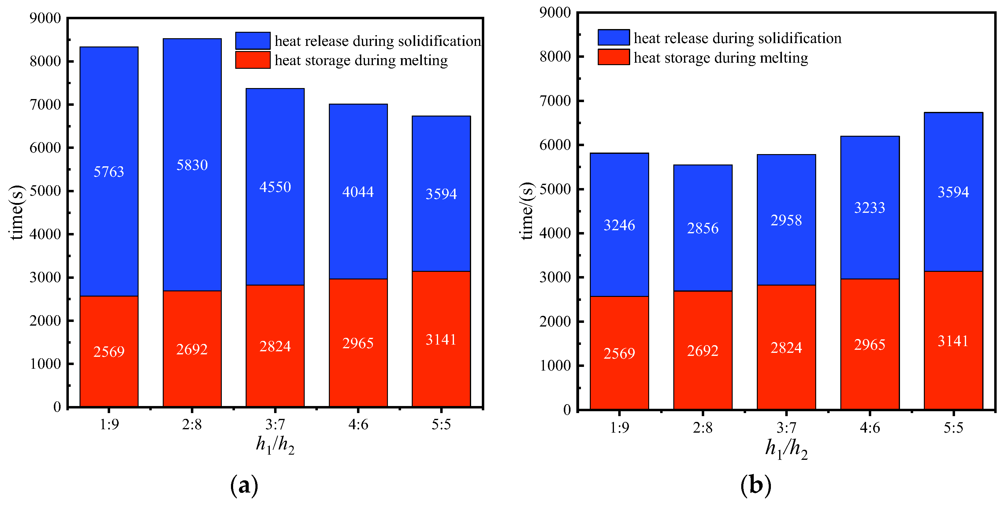
3.3. Comprehensive Thermal Energy Storage and Release Performance

The impact of various fin configurations on the TESU varies, with one of the criteria for assessing their effectiveness being the duration of thermal storage and release. Figure 8 presents the statistical analysis of thermal storage and release durations for the TESUs under different placement configurations. In Figure 8a, the storage units are placed in the upright position during both the melting and solidification processes. It is evident from the graph that the unit with an aspect ratio of h1/h2 = 1:9 exhibits the shortest melting duration, while its solidification time ranks second highest. Conversely, the unit with an aspect ratio of h1/h2 = 5:5 demonstrates the shortest solidification duration, yet it requires the longest time for melting. Consequently, the unit with an aspect ratio of h1/h2 = 5:5 shows the shortest overall thermal storage and release duration. In Figure 8b, the units are arranged in the upright position during the melting process and in the upside-down position during solidification. The unit with an aspect ratio of h1/h2 = 2:8 exhibits the shortest solidification duration, in contrast to the upright placement, where this structure ranks second. Interestingly, the unit with an aspect ratio of h1/h2 = 5:5, which is the fastest in melting under upright conditions, becomes the slowest under the upside-down placement. Comparing the two placements, the unit with the shortest thermal storage and release duration in the second arrangement saves 17.62% of the time compared to its counterpart in the upright position and reduces the duration by 34.90% compared to the slowest structure in the upright arrangement. These results indicate that the performance is consistent between the two structures, with only the placement method differing.

4. Conclusions

The simulation investigated the influence of trapezoidal fin sizes (h1/h2 = 1:9, 2:8, 3:7, 4:6, 5:5) on the thermal energy storage and release process of the TESU, as well as the effects of different placement configurations (upright and upside-down) on the solidification process of the storage unit. The main conclusions are as follows:
  • During the melting process, the fin structure with h1/h2 = 1:9 exhibited the most optimal enhancement in heat transfer for the storage unit, resulting in a reduction of the melting time by 18.24% compared to the structure with h1/h2 = 5:5;
  • During the solidification process, when the storage unit was upright, the structure with h1/h2 = 5:5 enhanced heat transfer best, resulting in a decrease in the heat storage time by 37.64% compared to the unit with h1/h2 = 1:9. Conversely, when the storage unit was placed upside-down, the unit with h1/h2 = 2:8 demonstrated the best enhancement in heat transfer, resulting in a reduction of the heat storage time by 20.6% compared to the unit with h1/h2 = 5:5;
  • When heat storage and release are considered together, the unit with h1/h2 = 5:5 shows the shortest overall energy storage and release time, with the energy storage unit placed in the upright position during both melting and solidification processes. The energy storage unit with h1/h2 = 2:8 takes the shortest time to melt in the upright placement and then to solidify in the upside-down placement.

Author Contributions

Conceptualization and methodology, M.X.; software, validation C.Y.; formal analysis, investigation, writing and editing, H.L.; supervision and project administration, Y.Z. All authors have read and agreed to the published version of the manuscript.

Funding

This work was supported by the National Natural Science Foundation of China (Grant No. 52166009).

Data Availability Statement

Data are contained within the article.

Conflicts of Interest

The authors declare no conflicts of interest.

References

  1. Cui, H.T.; Zhang, G.; Jiang, J.Z. Numerical simulation on thermal performance of multiple-pipe heat storage. Fluid Mach. 2014, 42, 56–61. [Google Scholar]
  2. Hei, Y.X.; Qu, M.L.; Huang, P.; Zhang, T.Y.; Li, Z. Study on multi-temperature heat release characteristics of phase change heat storage. Fluid Mach. 2022, 50, 21–26. [Google Scholar]
  3. Lin, D.G.; Mao, Y.N.; Li, X.H. Simulation study on the heat storage characteristics of the internal fin type casing phase change regenerator. Fluid Mach. 2021, 49, 84–89. [Google Scholar]
  4. Huang, K.L.; Chang, Q.P.; Song, J.S.; Feng, G.; Liu, K. Analysis of influence factors to heat transfer of concentric tube air type phase change heat accumulator. Fluid Mach. 2018, 46, 74–78. [Google Scholar]
  5. Qu ML Zhang, T.Y.; Zhang, R.; Fan, Y. Experimental study on charge and discharge thermal efficiency of cascade air source heat pump phase change regenerator. Fluid Mach. 2019, 47, 66–71. [Google Scholar]
  6. Sun, J.C.; Du, P.; Li, P.S.; Zhang, Y.; Li, W. The numerical simulation about energy storage process of spiral tube phase-change energy storage box. Fluid Mach. 2017, 45, 76–81. [Google Scholar]
  7. Meng, F.; Che, C.; Wu, Y.; Wei, J.; Rong, J.; Yang, X.; Li, D.; Yang, R.; Wang, Z. Thermal Storage Performance of a Shell and Tube Phase Change Heat Storage Unit with Different Thermophysical Parameters of the Phase Change Material. Processes 2024, 12, 123. [Google Scholar] [CrossRef]
  8. Zhang, Y.; Fu, Q.; Liu, Y.; Lai, B.; Ke, Z.; Wu, W. Investigations of Lithium-Ion Battery Thermal Management System with Hybrid PCM/Liquid Cooling Plate. Processes 2023, 11, 57. [Google Scholar] [CrossRef]
  9. Ashok Kumar, J.; Muthuvel, S.; Issac Selvaraj, R.V.; Ramoni, M.; Shanmugam, R.; Pandian, R.S. Mechanical Property Comparison of Geopolymer Brick Dried by Electrical and Passive Solar Devices with Phase Change Material (Paraffin Wax). Processes 2024, 12, 28. [Google Scholar] [CrossRef]
  10. Yang, T.Y.; King, W.P.; Mil Jkovic, N. Phase change material-based thermal energy storage. Cell Rep. Phys. Sci. 2021, 2, 100540. [Google Scholar] [CrossRef]
  11. Yuan, Y.; Cao, X.; Xiang, B.; Du, Y. Effect of installation angle of fins on melting characteristics of annular unit for latent heat thermal energy storage. Sol. Energy 2016, 136, 365–378. [Google Scholar] [CrossRef]
  12. Wang, W.W.; Wang, L.B.; He, Y.L. Parameter effect of a phase change thermal energy storage unit with one shell and one finned tube on its energy efficiency ratio and heat storage rate. Appl. Therm. Eng. 2016, 93, 50–60. [Google Scholar] [CrossRef]
  13. Yang, X.; Lu, Z.; Bai, Q.; Zhang, Q.; Jin, L.; Yan, J. Thermal performance of a shell-and-tube latent heat thermal energy storage unit: Role of annular fins. Appl. Energy 2017, 202, 558–570. [Google Scholar] [CrossRef]
  14. Ren, Z.; Huang, H.; Gao, J.; Zhao, M. Analysis of heat transfer characteristics of three-dimensional tubular ribbed chase change heat storage unit. J. Chin. Soc. Power Eng. 2022, 42, 437–443. [Google Scholar]
  15. Zhang, S.; Pu, L.; Xu, L.; Dai, M. Study on dominant heat transfer mechanism in vertical smooth/finned-tube thermal energy storage during charging process. Appl. Therm. Eng. 2022, 204, 117935. [Google Scholar] [CrossRef]
  16. Zonouzi, S.A.; Dadvar, A. Numerical investigation of using helical fins for the enhancement of the charging process of a latent heat thermal energy storage system. J. Energy Storage 2022, 49, 104157. [Google Scholar] [CrossRef]
  17. Guo, J.; Wang, X.; Yang, B.; Yang, X.; Li, M.J. Thermal assessment on solid-liquid energy storage tube packed with non-uniform angled fins. Sol. Energy Mater. Sol. Cells 2022, 236, 111526. [Google Scholar] [CrossRef]
  18. Guo, J.; Liu, Z.; Yang, B.; Yang, X.; Yan, J. Melting assessment on the angled fin design for a novel latent heat thermal energy storage tube. Renew. Energy 2022, 183, 406–422. [Google Scholar] [CrossRef]
  19. Yang, X.; Wang, X.; Liu, Z.; Luo, X.; Yan, J. Effect of fin number on the melting phase change in a horizontal finned shell-and-tube thermal energy storage unit. Sol. Energy Mater. Sol. Cells 2022, 236, 111527. [Google Scholar] [CrossRef]
  20. Cieśliński, J.T.; Fabrykiewicz, M. Thermal Energy Storage with PCMs in Shell-and-Tube Units: A Review. Energies 2023, 16, 936. [Google Scholar] [CrossRef]
  21. Najim, F.T.; Mohammed, H.I.; Al-Najjar, H.M.T.; Thangavelu, L.; Mahmoud, M.Z.; Mahdi, J.M.; Tiji, M.E.; Yaïci, W.; Talebizadehsardari, P. Improved Melting of Latent Heat Storage Using Fin Arrays with Non-Uniform Dimensions and Distinct Patterns. Nanomaterials 2022, 12, 403. [Google Scholar] [CrossRef] [PubMed]
  22. Khodadadi, J.M.; Hosseinizadeh, S.F. Nanoparticle-enhanced phase change materials (NEPCM) with great potential for improved thermal energy storage. Int. Commun. Heat Mass Transf. 2007, 34, 534–543. [Google Scholar] [CrossRef]
  23. Vivekananthan, M.; Amirtham, V.A. Characterisation and thermophysical properties of graphene nanoparticles dispersed erythritol PCM for medium temperature thermal energy storage applications. Thermochim. Acta 2019, 676, 94–103. [Google Scholar] [CrossRef]
  24. Duan, J.; Xiong, Y.L.; Yang, D. Study on the effect of multiple spiral fins for improved phase change process. Appl. Therm. Eng. 2020, 169, 114966. [Google Scholar] [CrossRef]
Figure 1. Physical model of the trapezoidal fin TESU; (a) structural sketch of the model; (b) cross-section diagram.
Processes 12 01080 g001
Figure 2. Grid independence verification.
Processes 12 01080 g002
Figure 3. Model of the validated literature [24].
Processes 12 01080 g003
Figure 4. Model validation [24]; (a) the melting process; (b) the solidification process.
Processes 12 01080 g004
Figure 5. Liquid fraction distribution in melting process; (a) solid–liquid phase diagram; (b) instantaneous liquid phase fraction.
Processes 12 01080 g005
Figure 6. Temperature distribution and liquid fraction in solidification process; (a) temperature field distribution; (b) instantaneous liquid phase fraction.
Processes 12 01080 g006
Figure 7. Temperature distribution and liquid fraction in the solidification process when the TESU is placed backward; (a) temperature field distribution; (b) instantaneous liquid phase fraction.
Processes 12 01080 g007
Figure 8. Comparison of heat storage and release time of the TESU; (a) heat storage and release time when TESUs are placed in the upright position; (b) heat storage and release time for TESUs with melting in the upright and solidifying in the upside-down position.
Processes 12 01080 g008
Table 1. Physical properties of materials.
ParametersParaffinCopper
solidus temperature/K322.36
liquidus temperature/K334.14
latent heat of fusion/(J/kg)142,716.3
density/(kg/m3)902.28430
specific heat capacity/(J/(kg·K)2300375
thermal conductivity of the solid phase/(W/(m·K))0.2437108.86
thermal conductivity of the liquid phase/(W/(m·K))0.177
dynamic viscosity/(kg/(m·s))0.00324
thermal expansion coefficient/(K−1)0.005
Disclaimer/Publisher’s Note: The statements, opinions and data contained in all publications are solely those of the individual author(s) and contributor(s) and not of MDPI and/or the editor(s). MDPI and/or the editor(s) disclaim responsibility for any injury to people or property resulting from any ideas, methods, instructions or products referred to in the content.

