Article

Batch to Continuous: From Laboratory Recycle Trickle Bed Test Reactor Data to Full-Scale Plant Preliminary Design—A Case Study Based on the Hydrogenation of Resorcinol

1
Johnson Matthey Technology Centre, P.O. Box 1, Belasis Avenue, Billingham TS23 1LB, UK
2
Robinson Brothers Ltd., Phoenix Street, West Bromwich B70 0AH, UK
*
Authors to whom correspondence should be addressed.
Processes 2024, 12(5), 859; https://doi.org/10.3390/pr12050859
Submission received: 27 March 2024 / Revised: 19 April 2024 / Accepted: 22 April 2024 / Published: 25 April 2024

Abstract

:
The fine chemical and pharmaceutical sectors are starting to advocate for the use of flow chemistry due to reasons such as the environment, health and safety, efficiency, cost saving, and regulatory compliance. The use of a trickle bed or fixed bed system could replace a batch autoclave typically used for hydrogenation reactions. However, there are few studies that detail the process from laboratory proof of concept through design to commercial realization. This study, using the production of 1,3-cyclohexanedione from the catalytic hydrogenation of resorcinol as a case study, demonstrates how the laboratory-scale recycle trickle bed can be used for catalyst screening and selection. Further, design data are generated by operation over a range of design superficial velocities and operating pressures that are used to derive a design correlation that is then used to specify a single stream plant at a level of definition consistent with a Preliminary Design for capital cost estimation. Finally, the further actions required in terms of data generation to increase the level of definition and confidence to a sanction grade or final design are discussed.

1. Introduction

The chemical industry has embraced continuous production for decades, primarily in the sectors that produce one product on a large scale e.g., petrochemical and bulk chemicals such as ammonia [1], sulfuric acid [2], sodium hydroxide, and chlorine [3]. The pharmaceutical and fine and specialty chemical sectors have been slower to implement continuous production, primarily due to the requirement for more than one product on a smaller scale. However, the case for continuous manufacturing is very persuasive from an environmental and sustainable perceptive [4], and thus the sectors are starting to advocate for the use of flow chemistry due to environmental, health and safety (EHS), efficiency, cost saving, and regulatory compliance reasons [5]. Regulatory approval of several pharmaceutical products manufactured via continuous processes have been granted [5], such as Orkambi™ by Vertex in 2015, Prezista™ by Janssen in 2016, Verzenio™ by Ely Lilly in 2017, and Symdeko™ by Vertex in 2018, along with substantial investment in continuous manufacturing by major players in the pharmaceutical industry. This has been accompanied by numerous publications detailing the advantages of flow in chemical reactions [6,7,8,9,10,11,12,13,14,15,16,17,18,19,20,21], along with several vendors offering flow chemistry equipment at different scales to facilitate the transition from laboratory scale to industrial realization [22,23,24,25,26,27,28,29]. The focus has mainly been the reaction chemistry itself, but pre- and post-processing steps as well as process analytical technology and data storage must also form part of the overall strategy in the shift from batch to continuous operation.
Nevertheless, the requirement for the quick manufacturing of numerous products at various scales, while maintaining quality and safety, remains [6]. This begs the question; can multiple products be made using the same equipment or by utilizing the same footprint [30]? The consensus from industrial practitioners is that there is no “one size fits all” and that a modular approach should be employed. However, the range of chemical transformations that are required in the pharmaceutical/fine chemical sector is extensive; therefore, to exploit this fully, the development of continuous flow chemistry ‘know-how’ is essential to understanding the benefits and optimum routes for manufacturing. Companies will have varied experience in different chemical transformations, so the move to continuous will necessitate both in-house development and working closely with contract manufacturing (development) organizations (CM(D)O) to realize other transformations via continuous routes [31]. Although there is a plethora of commercial reactors advocated for continuous processing, the wide range of reaction conditions and different chemistries that can be involved means that investment in this technology can be challenging for an industry that has historically, for several reasons, been risk-averse. These designs of reactors are “solutions looking for a problem”, and thus, it is the reaction chemistry that should dictate the design of the reactor system and accompanying associated equipment [30].
The trickle bed represents the simplest continuous reactor concept for gas/liquid solid catalysed reactions. By virtue of the packed bed, it provides a very high-specification catalyst inventory. Trickle bed catalysts are typically extrudates or cylindrical-, trilobe-, or quadrilobed-shaped materials. They are randomly packed into a single adiabatic reactor shell and operated in downflow mode for both the liquid (generally the substrate) and the reactive gas. As such, there are two important mass transfer processes that may influence the observed reaction rate: from the gas into the liquid and the liquid diffusion with the catalyst pore network. As a result, these trickle bed reactions can commonly be rate-limited by the gasliquid mass transfer. Additionally, the catalyst extrudates will likely operate at “pellet effectiveness” values significantly less than unity; 50% or thereabouts is a reasonable first estimate. It is of course essential to take these transport limitations into account in addition to the reaction kinetics in reactor design.
According to the gas and liquid mass velocities, a number of distinct flow regimes have been identified, all with different mass transfer characteristics [32,33]. Unless detailed and validated models are available to the designer for the mass transfer in the given system, the impact of flow rate and flow regime needs to be established experimentally. Equally, the “pellet effectiveness” needs to be established if the design is to be based on intrinsic kinetics [34].
Trickle beds have been in widespread use in the oil refining and petrochemical industries for over 100 years where established testing, scale-up, and design methods are well established. The test reactor, typically 10–40 mm in diameter and up to 1 m in length, is filled “full” of catalyst pellets/extrudate particles and the interstitial voids are filled with inert fine particles (say 50–100 micron SiC particles) [35,36]. This moves the packed voidage to a first approximation from 0.4 to 0.16. The fine particles also dominate the structure of the two-phase flow, leading to an increase in liquid hold-up and thus longer liquid residence times [37]. This essentially allows the test reactor to be operated at design liquid hourly space velocities and thus allows testing on a once-through integral reactor basis. Scale-up and design is based on the arising data and, significantly, on prior knowledge including kinetic and hydrodynamic models as well as data from existing units.
For trickle bed applications in the fine chemicals industry, it may become the norm that only one or two units for a given reaction will ever be built. While hydrodynamic and mass transfer models are widely available in the literature, reliable kinetic modes are likely to be unavailable and prohibitively expensive to obtain in terms of elapsed time and the required experimental resources. Therefore, to enable the wider exploitation of the trickle bed for flow chemistry in the fine chemicals industry, an alternative approach is needed.
There has been significant attention in the literature on so-called “micro-trickle beds”. These are generally 2–5 mm diameter reactor tubes, say 300 mm in height and packed with catalyst powder of diameter 10–250 microns. There is a significant amount of literature on their use, as heat exchanger reactors for process intensification, e.g., the series of studies by Bavykin and co-workers on benzyl alcohol oxidation [38,39,40]. Furthermore, the reproducible behavior of these test reactors has been demonstrated, provided that a consistent packing procedure is followed [41,42]. The hydrodynamics are dictated by the fine catalyst particles, as was the case for the conventional fines-diluted approach discussed above. However, in oil and petrochemical applications, the surface tension and wetting angles of the liquid are incorporated in the design models and are unlikely to vary greatly. In fine chemical applications, changing the solvent could significantly change these physical properties, with a major impact on the hydrodynamics of the bed [43].
There are a number of reports on the scaling of data from commercially available micro-trickle bed test units [44,45]. However, scaling to a conventional, extrudate-packed commercial reactor is fraught with uncertainty regarding the hydrodynamics, mass transfer, and pellet effectiveness. While these may not be ideal for generating design data, this type of reactor is invaluable for catalyst screening and establishing the preferred temperature and pressure design space. In addition, it has the benefit of requiring only relatively small volumes of the substrate. An alternative approach to small-scale trickle bed testing is to run a small reactor, packed with extrudates (no fines) in recycle mode with the liquid and mass velocities at full-scale design rates (in the order of 1–20 mm s−1). The first detailed analysis of this approach was presented by Hickman et al. [46], although the concept does seem to be somewhat older than this [47,48]. This has the benefits of allowing operation at design velocities and thus full-scale hydrodynamics, given that low-pass conversion leads to, in reaction kinetics measurement terminology [49], gradientless operation. That is to say, this reactor configuration is inherently set up to measure extrinsic kinetic data (including both mass transport and kinetic effects), which can be used directly in a design model.
The present authors have used this design configuration extensively to collect data not only on trickle beds [34] but also on coated monoliths [34,50], a structured slurry bubble column [51,52], and homogenous catalyst gasliquid reactions [53]. The same concept has equally been used, as examples, to study the scale-up and design of trickle beds for wastewater denitrification [54], catalytic wet-air oxidation of bisphenol A [55], and the dehydrogenation of tetrahydrocarbazole [56]. The case study for this work was the synthesis of 1,3-cyclohexanedione, which is an important chemical intermediate in the pharmaceutical and agro-chemical industries. It can be synthesized through aldol condensation methods [57] but the preferred commercial manufacturing route is from selective hydrogenation of 1,3-benzenediol (resorcinol) using Raney-type nickel or platinum group metal catalyst (PGM) in batch operation [58,59]. The focus of this work is to design a viable continuous process. Modeling and simulation approaches can be employed to scale up hydrogenation processes [60] but this paper reports, for the first time, how data from this laboratory reactor set-up can be used directly to develop a full preliminary plant design.

2. Materials and Methods

2.1. Reagents

The resorcinol feedstock was provided by Robinson Brothers Ltd. The sodium hydroxide used was sodium hydroxide pellets (99.998%, Product Number 480878 from Sigma Aldrich, Gillingham, Dorset, UK). The catalysts were provided from Johnson Matthey’s Life Sciences Technologies Business, the details of which are provided in Table 1.

2.2. Experimental Reactor

This was the same 25.4 mm i.d. stainless steel reactor and set up as described in the authors’ previous reports of trickle bed testing in a recycle loop reactor for hydrogenation and oxidation reactions [34,50], wherein a more detailed description may be found. Based on the typical trickle bed mode of co-current downflow operation, the liquid was recirculated via a small receiver vessel and distributed at the reactor entry using a spray nozzle to ensure good distribution. The hydrogen was fed continuously to the top of the reactor. The process flow was depressurized through a backpressure valve prior to entry to the receiver, allowing gas disengagement and venting, minimizing end effects from dissolved hydrogen.

2.3. Charging the Reactor

The reactor was charged with the catalyst (cylindrical, pellet, trilobe, or extrudate). The packing procedure was stepwise: introducing 30 cm3 per step with tapping prior to adding the next portion [34], in accordance with the methodology described by Al-Dahhan et al. [35], noting, however, that no fines were used in the present investigation. The “packed” densities of the catalysts in the reactor are presented in Table 1.

2.4. Catalyst Activation

After charging the batch recycle reactor, the catalyst was activated using the procedure described in detail elsewhere [34]. Briefly, this comprises initially purging the system with nitrogen and then passing hydrogen over the catalyst at 250 cm3 min−1 while maintaining a total pressure of 4 barg and ramping the temperature at 3 K min−1 up to 393 K with a dwell time of 1 h at this temperature. The nickel catalyst was further processed by then ramping the temperature at 3 K min−1 up to 723 K with a further dwell time of 1 h under the hydrogen flow. Cooling of the reduced samples to reaction temperature was carried out under hydrogen.

2.5. Experimental Procedure

The liquid solution was made to mimic the commercial operation. Resorcinol (127 g) was added to a solution of sodium hydroxide pellets (54 g) dissolved in distilled water (194 g). This solution was then used to pre-wet the catalyst for an hour. The solution was then discharged and a fresh solution (300 cm3) was introduced. The typical experimental conditions that were varied are shown in Table 2. Samples (2 cm3) were extracted at regular intervals during the course of the reaction.

2.6. Analysis

From the samples extracted during the course of the experiment, 1 cm3 was neutralized with 0.45 cm3 of 37 wt. % HCl and was then mixed with acetone (2 cm3). The mixture of resorcinol and 1,3-cyclohexanedione was extracted with acetone and analyzed by a Varian 3400 gas chromatograph equipped with a flame ionization detector and a capillary column (Varian VF-5MS column 30 m × 0.32 mm 0.25 μm film thickness). The conversion for a given sample was evaluated by closure of the mass balance.

3. Results

The experimental study initially tested a range of commercially available catalysts believed to be suitable for this particular hydrogenation (Table 1). The reaction profile was used to infer key mechanistic information required for reactor design. The selected catalyst was tested under a range of temperature, mass velocity, and pressure conditions to determine the preferred design conditions. The data were then used to carry out a full-scale reactor design and flowsheeting exercise leading to a preliminary plant design.

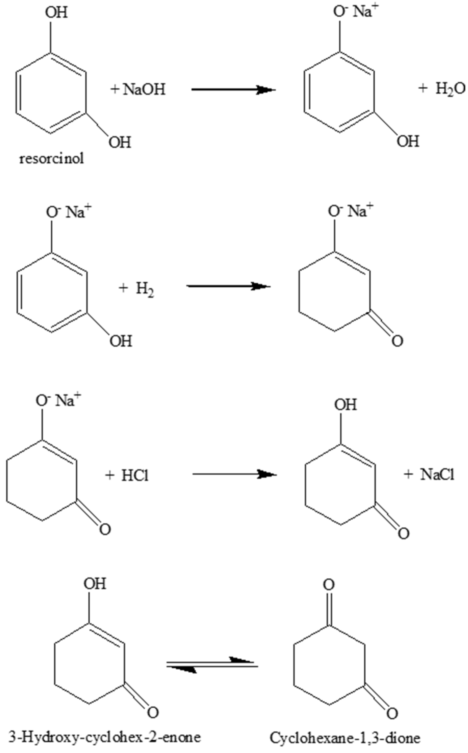
3.1. 1,3-Cyclohexanedione Formation

The experimental protocol described in Section 2.4 mimics the commercial procedure as it forms 1,3-cycloexanedione at a high yield and avoids significant byproduct formation, e.g., 1,3-cyclohexanediol [51,52,57]. The first step is the acid–base reaction between resorcinol and sodium hydroxide. The molar ratio of sodium hydroxide to resorcinol is 1.18, which has been reported to be the optimum for obtaining 1,3-cyclohexanediol in high yields [61]. After hydrogenation of the resorcinol salt, the product is then reacted with acid to obtain 1,3-cyclohexandione. It should be noted that 1,3-cyclohexanedione itself is unstable. It usually deteriorates on exposure to air, can be stored only for a short time, and has a tendency to give self-condensation products at higher temperatures in the presence of a catalyst (Scheme 1).

3.2. Catalyst Screening: Rate of Reaction over Catalysts

Figure 1 shows the hydrogenation of resorcinol over commercial Ni/Al2O3 catalyst trilobes as a function of time. Total conversion of resorcinol was observed. The results indicate that the reaction was zero order up to 80–85% conversion, after which the rate tends to be pseudo-first order, presumably because the catalyst:substrate ratio becomes greater than 1. This may be considered classical behavior for a substrate that absorbs strongly, but not sufficiently to cause substrate inhibition.
Table 3 shows the apparent rate of reaction for all catalysts studied. While the PGM catalysts were far more effective on a specific rate per gram of metal, on a total mass or volumetric basis, Ni/Al2O3 was the most promising candidate as a fixed bed catalyst for resorcinol hydrogenation to 1,3-cyclohexanedione. These results indicate a reactor volume five times smaller than the best PGM catalyst (Rh/C). Given the relative prices of the studied catalysts, reactor volume will dominate the relative plant costs. The Ni/Al2O3 catalysts are preferred from an operating (catalyst initial charge and replacement) and capital (reactor size and cost) perspective.

3.3. Reaction Parameters over the Ni/Al2O3 Catalyst

Figure 2 shows the zero-order reaction rate for the hydrogenation of resorcinol over the Ni/Al2O3 catalyst as a function of liquid superficial velocity. The rate of reaction increased as the superficial velocity was increased from 7 mm s−1 up to 14 mm s−1. It is expected that the trickle-to-pulse regime transition for this catalyst would occur at 8–10 mm s−1 for this size and type of extrudate [62,63,64]. The experimental range thus spans the flow regime transition.
Figure 3 shows the influence of pressure on the reaction rate. As would be expected for a reaction of this type, the reaction rate shows a first-order dependency on the hydrogen pressure. This is consistent with the zero-order interpretation of the earlier part of the reaction, and that the rate here is probably transport-limited.
Figure 4 shows an Arrhenius-type plot, where the natural logarithm of the reaction rate has been plotted against 1/Temperature (K) to determine an activation energy (Ea) for hydrogenation. The gradient of the line is −Ea·R−1, where R is the gas constant, which gives rise to an activation energy of 22 kJ mol−1. This value of 22 kJ mol−1 is quite low for hydrogenation and would commonly be used to infer a mass transfer limitation. A low activation energy was observed for this reaction in autoclave studies over a Rh/Al2O3 catalyst [52]; whereas, when the reaction was performed in a more structured system (capillary flow), the value was higher, indicating kinetic control consistent with the high rates of mass transport and mixing for multiphase flow in more structured reactors. This is consistent with the first-order pressure dependency observed above.
As noted above, the liquid superficial velocity exerts a moderate influence on the observed reaction rate. This can be taken to infer a degree of external (gas/liquid) mass transfer influence on the process. A detailed analysis of the mass transfer for a trickle bed in a hydrogenation reaction was given in our previous paper [34], where trickle bed operation in both trickle flow and transition regimes was found to be significantly influenced by intra-pellet mass transfer; pellet effectiveness in the order of 50% was estimated. Given the similarity of the overall rate, this also may be expected in this study. However, returning to the external influence, the operating liquid rates span the expected transition from a trickle regime to a pulsing regime with a consequential increase in mass transfer efficiency. Therefore, overall, the reaction process is significantly influenced by both external and internal mass transfer: the rates measures are definitively apparent or extrinsic, rather than intrinsic, in their nature.
There was a significant impact of temperature on reaction selectivity. As noted earlier, at higher temperatures, byproducts were observed. These are presumably self-condensation products from 1,3-cyclohexanedione in the presence of a catalyst.
A multi-variate analysis of the experimental data can be completed to obtain a design correlation for the zero-order portion of the reaction below, for which the fitting parity plot is shown in Figure 5.
R a t e     U L 0.2   ·   p H 2   · e 2500 T K
where UL is the liquid superficial velocity (mm/s), pH2 is the hydrogen partial pressure (bara), and TK is the temperature (K). In the study, to the point reported herein for the purposes of generating a preliminary design, the data volume in the first-order regime is not sufficient to generate a meaningful equivalent correlation. The design of that column is thus, by necessity, based on a more empirical approach.

4. Preliminary Plant Design

Analysis of the obtained products from the commercial Ni/Al2O3 catalyst hydrogenation studies indicated that reaction selectivity was good, with a high yield of 1,3-cyclohexanedione. When isolated, the 1,3-cyclohexanedione solid was of “good color” and filtered very well. The yield was noted as being comparable to that from autoclave studies carried out at Robinson Brothers Ltd. on a sponge-metal (nickel) catalyst. Therefore, the trickle bed reactor was able to produce a product of a quality at least comparable to that of the traditional autoclave.

4.1. Design Philosophy

A number of key observations from the experimental data influenced the reactor design strategy for the industrial application:
  • The selectivity and product quality declined significantly for isothermal run temperatures significantly above 343 K. The byproducts leading to poor yield and color were largely derived from the product. When the temperature was significantly below 333 K, catalyst activity was low. The preferred design temperature of 343 ± 5 K is therefore specified.
  • The enthalpy of the reaction is estimated to be 105 kJ mol−1 (exothermic) and there will be a significant adiabatic temperature rise (ca. 80 K). Therefore, cooling must be provided to maintain the temperature largely between 338 and 348 K. Trickle bed reactors themselves are essentially adiabatic, so the reactor flowsheeting must accommodate this. Adequate mass transfer and reaction rates were obtained in the trickle bed under the selected process conditions, more specifically across the range of liquid mass velocities.
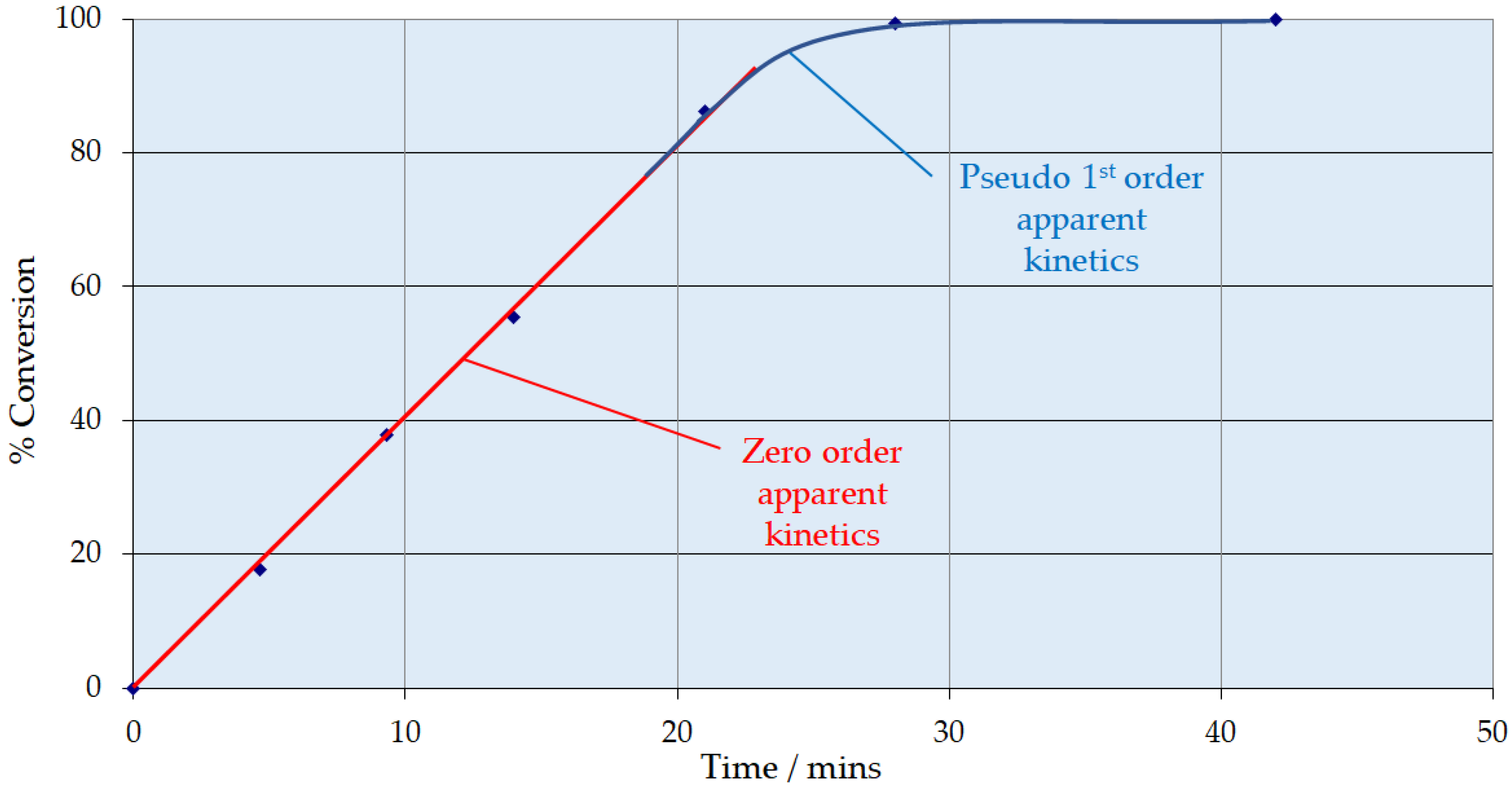
  • The zero-order behavior observed below 85% conversion is fortuitous. This means that the same resorcinol reaction rate is obtained irrespective of its concentration. This affords a solution to the adiabatic temperature rise issue. A first column can be designed to run with a recycle loop to limit pass conversion for the allowable temperature rise.
  • A bleed from this recycle loop will be taken forward to a second, single-pass column that will take the reaction through to complete conversion, operating in the first-order reaction rate domain.

4.2. Process Flowsheet

A process flowsheet and mass balance summary for a continuous hydrogenation resorcinol plant that would produce 1,3-cyclohexanedione (2000 metric tons per annum) with a composition suitable for a hydrogenation plant for resorcinol was designed using the information in Figure 1, Figure 2, Figure 3 and Figure 4. LHSVs were estimated from the laboratory experiments described earlier, and the reactor catalyst volumes were estimated from the flow rate determined from the plant mass balance for the desired plant throughput. The flow diagram from the process flowsheet is shown in Figure 6. The design is based on the reaction profile as shown in Figure 1, where the reaction at concentrations corresponding to <80–85% conversion was substantially zero-order in resorcinol, with no observed inhibition from product adsorption. The majority of the reaction may, therefore, be conducted in a single reactor (C100 in Figure 6) with product stream recycling. This reactor should convert approximately 85% of the plant’s resorcinol feed. The recycle ratio should be selected to control the per-pass temperature rise to within acceptable limits. A purge from the recycle loop should then be fed to a second “polish” trickle bed (C200 in Figure 6) that will be used to hydrogenate the remaining resorcinol (first-order reaction regime) in a single pass.
As noted above, there are two hydrogenation reactors; the first one (C100) is designed to convert 85% of resorcinol at an inlet temperature of 333 K and a nominal design pressure of 7 barg as described above. The second reactor (C200) is designed to convert the remaining resorcinol at 333 K at a nominal design pressure of 7 barg. The feed composition of resorcinol, sodium hydroxide, and water is fed from a preparation feed tank, which may be available from existing vessels. The feed preparation tank will require moderate agitation and may require jacketing due to heat generation from the addition of caustic materials to water (not accounted for). The hydrogen gas is fed from a hydrogen storage vessel.
The starting liquid feed solution (S101) is introduced (S103) to the first hydrogenation reactor (C100). The gas feed (S105) is introduced to the first hydrogenation reactor (C100). The liquid hydrogenation products exit the reactor (S106). Any remaining gas that is not consumed (S202) is passed to the second hydrogenation reactor (C200). The liquid feed (S106) is cooled via a heat exchanger (E102). The majority of this liquid stream (S107) is recycled back (with a recycle ratio of 5:1), mixed with the starting liquid stream (S108), and fed (S102) to the hydrogenation reactor (C100). This recycling loop is necessary to mitigate the adiabatic temperature rise in the hydrogenation reactor (C100) so that the exit stream (S106) is at a temperature of 343 K, i.e., a 10 K exotherm in the reactor.
The hydrogenated liquid feed solution (S201) is introduced to the second hydrogenation reactor (C200). The gas feed (S202) is introduced to the second hydrogenation reactor (C200). The liquid hydrogenation products exit the reactor (S203). Any remaining gas that is not consumed (S204) is vented or recycled according to the needs of the plant (S205). The liquid feed (S203) is cooled via a heat exchanger (E201). The cooled liquid feed (S301) is reduced from 7 bar down to 1 bar atmospheric. The liquid product is treated with hydrochloric acid (which is not accounted for), which may need to be jacketed due to heat generation from the neutralization reaction (acid and base). The product stream is then treated to produce the desired 1,3-cyclohexanedione product. The feed to the reactor (C200) could be preheated to near the feed section temperature by heat exchange with product streams.

4.3. Main Plant Items

To obtain more realistic costings, the sizes and duties of the main plant items (reactors, heat exchangers, pumps, and compressors) need to be identified based on the experimental data. This estimate would be for a unit responsible for the continuous hydrogenation of resorcinol, producing 2000 metric tons per annum of product. Figure 7 shows how the preliminary trickle bed reactor (first hydrogenation vessel C100) can be designed. The catalyst volume required is 2.6 m3 for a reactor diameter of 0.4 m, giving a bed height of 20 m. While data generated to date indicate the absence of acute deactivation and this commercial catalyst generally exhibits long lifetimes, there are no specific data presently on chronic effects. This volume therefore includes an arbitrary but experiential 20% design margin to account for catalyst deactivation. Increasing the diameter of the reactor decreases the height of the catalyst bed but more catalyst volume is required due to the dependence on liquid mass velocity. Figure 8 shows the impact of superficial velocity on the relative cost of the reactor. Increasing superficial velocity lowers the cost of the reactor and catalyst costing, which is a positive result considering that increasing superficial velocity increases the rate of the reaction (Figure 2). Figure 9 shows the impact of superficial velocity on the polishing reactor (second hydrogenation reactor C200). Increasing the reactor’s diameter means that reduced trickle bed height and superficial velocities are required for a realistic reactor design. Operation of the polishing reactor (C200) implies that low superficial velocities are required. While a small diameter extrudate may ostensibly be beneficial for reasons related largely to internal mass transfer mitigation in this operating mode, the desired solution in the present study was for an established commercial catalyst. Therefore, this was not taken into consideration.
The design sizing of the other main plant items required for a preliminary design costing was achieved using simple approximate standard design approaches. For example, the heat exchanger duties are defined by the energy balance and the heat exchange area (the key parameter for costing purposes). This can be determined simply from Q = U·A·ΔT, where Q is the heat exchanger duty (W), U is the overall heat transfer coefficient (W·m−2·K−1), A is the heat exchanger area, and ΔT is the logarithmic mean temperature difference (K). Equally, the sizing of the pumps can be sized by using the flow rate (defined in the mass balance), with the required head estimated by the elevation of the delivery (the column heights) and P = ρ·g·H multiplied by a suitable design margin to account for pipeline friction losses, where P is the delivery Pressure (N·m−2), ρ is the fluid density (kg·m−3), g is the gravitational constant (9.81 m·s−2), and H is the column height (m).

4.4. Preliminary Cost Estimate

The information from this experimental program and the process flowsheet and mass balance can be used to obtain a preliminary cost estimate for the main plant items, e.g., reactor sizing, heat exchange duty, and pump and compression, for a continuous hydrogenation resorcinol plant designed to produce 1,3-cyclohexanedione for a given production rate per year. It is recommended that capital cost estimates be made using the factorial costing approach [65,66]. Main plant item costs can be obtained by vendor estimates, bearing in mind the materials of construction required for the high-alkalinity feed stream. Multiple (rather than) single installation factors should be applied. Mid-range Lang factor values should be used. The plant is pretty small so some installation factors (e.g., instrumentation, piping) are unusually high. The capital cost considerations for continuous operation have been addressed in numerous publications [8,9,31,67,68]. This estimate can be used to move from an initial screening stage to an extended evaluation [69]. An important factor is that the design is based on a packed (fixed) trickle bed catalyst. While this is advantageous over the use of a slurry catalyst in that the need for catalyst filtration, separation, and recycling is circumvented, an important aspect is to ensure that the trickle bed is durable enough for infrequent change out (replacement) [70]. Some fixed bed catalyst systems have lifetimes of several years but that depends on the chemical transformation [71,72].

4.5. Beyond Preliminary Design

The discussion above has presented how the data from the recycle trickle bed reactor can be used for a plant preliminary design. The data and methods presented herein are quite sufficient and adequate for the purpose of generating a Preliminary Estimate (nominally ±30%). If, however, plant design and specification are to progress beyond this stage, additional data will be required. The discussion above has highlighted that the data volume and variety are not yet sufficient for detailed plant design. Moreover, the sampling frequency in the pseudo-first-order regime is clearly not adequate to allow determination of a reliable apparent kinetic model for design and optimisation purposes.
It should be emphasized that the recycle trickle bed data alone are not sufficient. Most importantly, they give no information on chronic catalyst deactivation. Longer-term testing in a micro-trickle bed or a conventional packed bed with fines is essential for this purpose. Traditional trials using a trickle bed packed with fines may be a requirement for customer confidence and high-conversion demonstration purposes but are not essential for design purposes alone. However, in either of these, it is essential to also mimic the likely temperature profiles, which might require heat transfer to be built into the test reactor design.

5. Conclusions

This investigation has shown that commercial Ni/Al2O3 is a most promising candidate as a fixed bed catalyst for resorcinol hydrogenation to 1,3-cyclohexanedione. The data obtained from the batch recycle tests have been used to construct a process flowsheet, giving information about main plant items to generate a capital cost estimate. The utilization of a fixed (packed) bed catalyst over a slurry catalyst is that the need for catalyst filtration, separation, and recycling is circumvented. However, this does cause a loss in flexibility for multi-product production. This loss of flexibility is a major inhibitor in terms of the take up of fixed bed reactors in intermediate-scale chemicals manufacturing. However, it can be argued this application is for a small commercial unit and that the flowsheet shown in Figure 6 is generic for hydrogenation reactions demonstrating zero-order kinetics (no inhibition from the reactant or product). In addition, the equipment could be used for similar chemical transformations utilizing the same footprint. It is important to highlight that the use of heterogeneous catalysts in flow for fine chemical applications has relatively recently begun to be explored and that packed bed platforms are available, yet probably underutilized by the fine chemical and pharmaceutical companies and CM(D)Os. This is attributed to the added complexity of developing these reactions and platforms where catalyst deactivation, adsorption variables, complex fluid and vapour dynamics, and the continuously changing state of the catalyst bed are all parameters that can vary from reaction to reaction. However, there is extensive experience in the use of packed bed technology which can be utilized to exploit the technology in the fine chemical sector.

Author Contributions

Conceptualization, E.H.S.; methodology, E.H.S. and S.D.P.; formal analysis, B.S.K. and S.D.P.; investigation, S.D.P.; data curation, S.D.P. and E.H.S.; writing—original draft preparation, S.D.P.; writing—review and editing, E.H.S.; supervision, E.H.S.; project administration, B.S.K. and E.H.S.; funding acquisition, E.H.S. All authors have read and agreed to the published version of the manuscript.

Funding

This research was partly funded by Engineering and Physical Sciences Research Council U.K. (EPSRC) for the funding for this work under the Controlling the Access of Reactant Molecules to Active Centres (CARMAC) programme GR/S43702/01.

Data Availability Statement

No new Data were created.

Acknowledgments

The authors thank the Engineering and Physical Sciences Research Council U.K. (EPSRC) under the Controlling the Access of Reactant Molecules to Active Centres (CARMAC) programme GR/S43702/01, which was carried out at the Johnson Matthey Technology Centre in Billingham. The authors wish to thank Ken Hindle (Queens University, Belfast) for experimental work, Steve Hawker (Johnson Matthey) for catalysts used in this work, and Colin Baptist (Johnson Matthey) and Ken Rock (Robinson Brothers Ltd.) for their help with analysis. The authors thank Johnson Matthey plc and Robinson Brothers Ltd. for permission to publish this work.

Conflicts of Interest

Authors Steve D. Pollington and E. Hugh Stitt are employed by the Johnson Matthey Technology Centre. Author Bal S. Kalirai is employed by the company Robinson Brothers Ltd. The companies provided pledged in-kind contribution to a funded university programme which included Queens University, Robinson Brothers and Johnson Matthey. The authors were bound and adhered to the ethical demands demanded by their respective companies and by the funding body, the Engineering and Physical Sciences Research Council (EPSCR) U.K.

References

  1. Brightling, J. Ammonia and the Fertiliser Industry: The Development of Ammonia at Billingham. A history of technological innovation from the early 20th century to the present day. Johns. Matthey Technol. Rev. 2018, 62, 32–47. [Google Scholar] [CrossRef]
  2. King, M.; Moats, W.; Davenport, W. Sulfuric Acid Manufacture. Analysis, Control and Optimization, 2nd ed.; Elsevier: Amsterdam, The Netherlands, 2013. [Google Scholar]
  3. Brinkmann, T.; Santonja, G.G.; Schorcht, F.; Roudier, S.; Delgado Sancho, L. Best Available Techniques (BAT). Reference Document for the Production of Chlor-alkali. In JRC Science and Policy Reports; European Commission: Brussels, Belgium, 2014. [Google Scholar]
  4. Blacker, A.J.; Breen, J.R.; Bourne, R.A.; Hone, C.A. The Growing Impact of Continuous Flow Methods on the Twelve Principles of Green Chemistry. In Green and Sustainable Medicinal Chemistry: Methods, Tools and Strategies for the 21st Century Pharmaceutical Industry; Summerton, L., Sneddon, H.F., Jones, L.C., Clark, J.H., Eds.; The Royal Society of Chemistry: London, UK, 2016; Chapter 12; pp. 140–155. [Google Scholar]
  5. Dilley, G. Continuous Manufacturing at Johnson Matthey for Pharmaceutical Applications. Johns. Matthey Technol. Rev. 2019, 63, 148–149. [Google Scholar] [CrossRef]
  6. Gutmann, B.; Cantillo, D.; Kappe, C.O. Continuous-Flow Technology—A Tool for the Safe Manufacturing of Active Pharmaceutical Ingredients. Angew. Chem. Int. Ed. 2015, 54, 6688–6728. [Google Scholar] [CrossRef]
  7. Baumann, M.; Baxendale, I.R. The Synthesis of Active Pharmaceutical Ingredients (APIs) using Continuous Flow Chemistry. Beilstein J. Org. Chem. 2015, 11, 1194–1219. [Google Scholar] [CrossRef] [PubMed]
  8. Baumann, M.; Moody, T.S.; Smyth, M.; Wharry, S. A Perspective on Continuous Flow Chemistry in the Pharmaceutical Industry. Org. Process Res. Dev. 2020, 24, 1802–1813. [Google Scholar] [CrossRef]
  9. Porta, R.; Benaglia, M.; Puglisi, A. Flow Chemistry: Recent Developments in the Synthesis of Pharmaceutical Products. Org. Process Res. Dev. 2016, 20, 2–25. [Google Scholar] [CrossRef]
  10. Guan, F.; Kapur, N.; Sim, L.; Taylor, C.J.; Wen, J.; Zhang, X.; Blacker, A.J. A Universal Reactor Platform for Batch and Flow: Application to Homogeneous and Heterogeneous Hydrogenation. React. Chem. Eng. 2020, 5, 1903–1908. [Google Scholar] [CrossRef]
  11. Calabrese, G.S.; Pissavini, S. From Batch to Continuous Flow Processing in Chemicals Manufacturing. AIChE J. 2011, 57, 828–834. [Google Scholar] [CrossRef]
  12. Costandy, J.G.; Edgar, T.F.; Baldea, M. Switching from Batch to Continuous Reactors is a Trajectory Optimization Problem. Ind. Eng. Chem. Res. 2019, 58, 13718–13736. [Google Scholar] [CrossRef]
  13. Morschhäuser, R.; Krull, M.; Kayser, C.; Boberski, C.; Bierbaum, R.; Püschner, P.A.; Glasnov, T.N.; Kappe, C.O. Microwave-Assisted Continuous Flow Synthesis on Industrial Scale. Green Process. Synth. 2012, 1, 281–290. [Google Scholar] [CrossRef]
  14. Newman, S.G.; Jensen, K.F. The Role of Flow in Green Chemistry and Engineering. Green Chem. 2013, 15, 1456–1472. [Google Scholar] [CrossRef]
  15. Kashid, M.M.; Kiwi-Minsker, L. Microstructured Reactors for Multiphase Reactions: State of the Art. Ind. Eng. Chem. Res. 2009, 48, 6465–6485. [Google Scholar] [CrossRef]
  16. Schrickel, J. Continuous Processes-Sustainable Manufacturing. Chem. Today 2013, 31, 22–25. [Google Scholar]
  17. Loh, G.; Tanigawara, R.; Shaik, S.M.; Sa-ei, K.; Wong, L.; Sharratt, P.N. Manufacture of a b-Hydroxyester via a Continuous Reformatsky Process. Org. Process Res. Dev. 2012, 16, 958–966. [Google Scholar] [CrossRef]
  18. Wong, L.; Wong, R.L.; Loh, G.; Tan, P.E.W.; Teoh, S.K.; Shaik, S.M.; Sharratt, P.N.; Chew, W.; Tan, S.T.; Wang, D. Multikilogram Synthesis of 4-D-Erythronolactone via Batch and Continuous Processing. Org. Process Res. Dev. 2012, 16, 1003–1012. [Google Scholar] [CrossRef]
  19. Lee, S.L.; O’Connor, T.F.; Yang, X.; Cruz, C.N.; Chatterjee, S.; Madurawe, R.D.; Moore, C.M.V.; Yu, L.X.; Woodcock, J. Modernizing Pharmaceutical Manufacturing: From Batch to Continuous Production. J. Pharm. Innov. 2015, 10, 191–199. [Google Scholar] [CrossRef]
  20. Halford, B. Process Chemistry: Flow Chemistry Advanced in Industry. Chem. Eng. News 2017, 95, 23. [Google Scholar]
  21. Plutschack, M.B.; Pieber, B.; Gilmore, K.; Seeberger, P.B. The Hitchhiker’s Guide to Flow Chemistry. Chem. Rev. 2017, 117, 11796–11893. [Google Scholar] [CrossRef]
  22. Available online: https://thalesnano.com/ (accessed on 22 January 2024).
  23. Available online: https://www.vapourtec.com/ (accessed on 22 January 2024).
  24. Available online: https://www.uniqsis.com/ (accessed on 22 January 2024).
  25. Available online: https://syrris.com/ (accessed on 22 January 2024).
  26. Available online: https://www.lonza.com/ (accessed on 22 January 2024).
  27. Available online: https://www.corning.com (accessed on 22 January 2024).
  28. Available online: https://ehrfeld.com/ (accessed on 22 January 2024).
  29. Available online: https://www.chemtrix.com/ (accessed on 22 January 2024).
  30. Holtze, C.; Boehling, R. Batch or Flow chemistry?—A Current Industrial Opinion on Process Selection. Curr. Opin. Chem. Eng. 2022, 36, 100798. [Google Scholar] [CrossRef]
  31. McWilliams, J.C.; Allian, A.D.; Opalka, S.M.; May, S.A.; Journet, M.; Braden, T.M. The Evolving State of Continuous Processing in Pharmaceutical API Manufacturing: A Survey of Pharmaceutical Companies and Contract Manufacturing Organizations. Org. Process Res. Dev. 2018, 22, 1143–1166. [Google Scholar] [CrossRef]
  32. Baker, O. Simultaneous Flow of Oil and Gas. Oil Gas J. 1954, 53, 185–195. [Google Scholar]
  33. Sie, S.T.; Krishna, R. Process Development and Scale Up: III. Scale-up and scale down of Trickle Bed Processes. Rev. Chem. Eng. 1998, 14, 203–252. [Google Scholar] [CrossRef]
  34. Enache, D.I.; Landon, P.; Lok, C.M.; Pollington, S.D.; Stitt, E.H. Direct Comparison of a Trickle Bed and a Monolith for Hydrogenation of Pyrolysis Gasoline. Ind. Eng. Chem. Res. 2005, 44, 9431–9439. [Google Scholar] [CrossRef]
  35. Al-Dahhan, M.H.; Wu, Y.; Dudukovic, M.P. Reproducible Technique for Packing Laboratory Scale Trickle Bed Reactors with a Mixture of Catalyst and Fines. Ind. Eng. Chem. Res. 1995, 34, 741–747. [Google Scholar] [CrossRef]
  36. Al-Dahhan, M.H.; Dudukovic, M.P. Catalyst Bed Dilution for Improving Catalyst Wetting in Laboratory Trickle-bed Reactors. AIChE J. 1996, 42, 2594–2606. [Google Scholar] [CrossRef]
  37. Kulkarni, R.R.; Wood, J.; Winterbottom, J.M.; Stitt, E.H. Effect of Fines and Porous Catalyst on Hydrodynamics of Trickle Bed Reactors. Ind. Eng. Chem. Res. 2005, 44, 9497–9501. [Google Scholar] [CrossRef]
  38. Bavykin, D.V.; Lapkin, A.A.; Kolaczkowski, S.T.; Plucinski, P.K. Selective Oxidation of Alcohols in a Continuous Multifunctional Reactor: Ruthenium Oxide Catalysed Oxidation of Benzyl Alcohol. Appl. Catal. A Gen. 2005, 288, 175–184. [Google Scholar] [CrossRef]
  39. Plucinski, P.K.; Bavykin, D.V.; Kolaczkowski, S.T.; Lapkin, A.A. Application of a Structured Multifunctional Reactor for the Oxidation of a liquid Organic Feedstock. Catal. Today 2005, 105, 479–483. [Google Scholar] [CrossRef]
  40. Plucinski, P.K.; Bavykin, D.V.; Kolaczkowski, S.T.; Lapkin, A.A. Liquid-Phase Oxidation of Organic Feedstock in a Compact Multichannel Reactor. Ind. Eng. Chem. Res. 2005, 44, 9683–9690. [Google Scholar] [CrossRef]
  41. van Herk, D.; Kreutzer, M.T.; Makkee, M.; Moulijn, J.A. Scaling Down Trickle Bed Reactors. Catal. Today 2005, 106, 227–232. [Google Scholar] [CrossRef]
  42. van Herk, D.; Castaño, P.; Makkee, M.; Moulijn, J.A.; Kreutzer, M.T. Catalyst Testing in a Multiple-parallel, Gas–Liquid, Powder-packed bed Microreactor. Appl. Catal. A Gen. 2009, 365, 199–206. [Google Scholar] [CrossRef]
  43. Krishnamurthy, S.; Peles, Y. Surface Tension effects on Adiabatic gas–liquid flow across micro pillars. Int. J. Multiph. Flow 2009, 35, 55–65. [Google Scholar] [CrossRef]
  44. Spadoni, C.; Jones, R.V.; Urge, L.; Darvas, F. Scaling up and Validation of Hydrogenation reactions using a Continuous-flow Microfluidics-based reactor, H-Cube®. Chem. Today 2006, 1, 38–41. [Google Scholar]
  45. Szöllösi, G.; Hermán, B.; Fülöp, F.; Bartók, M. Continuous enantioselective hydrogenation of activated ketones on a Pt-CD chiral catalyst: Use of H-Cube reactor system. React. Kinet. Catal. Lett. 2006, 88, 391–398. [Google Scholar] [CrossRef]
  46. Hickman, D.A.; Weidenbach, M.; Friedhoff, D.P. A Comparison of a Batch Recycle Reactor and an Integral Reactor with Fines for Scale-up of an Industrial Trickle Bed Reactor from Laboratory Data. Chem. Eng. Sci. 2004, 59, 5425–5430. [Google Scholar] [CrossRef]
  47. Papayannakos, N.; Marangozis, J. Kinetics of Catalytic Hydrodesulfurization of a Petroleum Residue in a Batch Recycle Trickle Bed Reactor. Chem. Eng. Sci. 1984, 39, 1051–1061. [Google Scholar]
  48. Gu, Q.; Mao, Z.; Zhu, Y. The Experimental Investigation of Catalytic Reaction Processes in Trickle Beds. J. Chem. Ind. Eng. 1986, 1, 120–127. [Google Scholar]
  49. Berger, R.J.; Stitt, E.H.; Marin, G.B.; Kapteijn, F.; Moulijn, J.A. Chemical Reaction Kinetics in Practice. CATTECH 2001, 5, 30–60. [Google Scholar] [CrossRef]
  50. Pollington, S.D.; Enache, D.I.; Landon, P.; Meenakshisundaram, S.; Dimitratos, N.; Wagland, A.; Hutchings, G.J.; Stitt, E.H. Enhanced Selective Glycerol Oxidation in Multiphase Structured Reactors. Catal. Today 2009, 145, 169–175. [Google Scholar] [CrossRef]
  51. Enache, D.I.; Hutchings, G.J.; Taylor, S.H.; Natividad, R.; Raymahasay, S.; Winterbottom, J.M.; Stitt, E.H. Experimental Evaluation of a Three-Phase Downflow Capillary Reactor. Ind. Eng. Chem. Res. 2005, 44, 6295–6303. [Google Scholar] [CrossRef]
  52. Enache, D.I.; Hutchings, G.J.; Taylor, S.H.; Raymahasay, S.; Winterbottom, J.M.; Mantle, M.D.; Sederman, A.J.; Gladden, L.F.; Chatwin, C.; Symonds, K.T.; et al. Multiphase Hydrogenation of Resorcinol in Structured and Heat Exchange Reactor Systems. Influence of the Catalyst and the Reactor Configuration. Catal. Today 2007, 128, 26–35. [Google Scholar] [CrossRef]
  53. Enache, D.I.; Thiam, W.; Dumas, D.; Ellwood, S.; Hutchings, G.J.; Taylor, S.H.; Hawker, S.; Stitt, E.H. Intensification of the solvent-free catalytic hydroformylation of cyclododecatriene: Comparison of a stirred batch reactor and a heat-exchange reactor. Catal. Today 2007, 128, 18–25. [Google Scholar] [CrossRef]
  54. Allison, M.; Bergquist, A.M.; Madison Bertoch, M.; Gildert, G.; Strathmann, T.J.; Werth, C.J. Catalytic Denitrification in a Trickle Bed Reactor: Ion Exchange Waste Brine Treatment. J. AWWA 2017, 109, E129–E151. [Google Scholar]
  55. Kaplan, R.; Erjavec, B.; Senila, M.; Pintar, A. Catalytic wet air oxidation of bisphenol A solution in a batch-recycle trickle-bed reactor over titanate nanotube-based catalysts. Environ. Sci. Pollut. Res. 2014, 21, 11313–11319. [Google Scholar] [CrossRef] [PubMed]
  56. Shen, Y.; Maamor, A.; Abu-Dharieh, J.; Thompson, J.M.; Kalirai, B.; Stitt, E.H.; Rooney, D.W. Moving from Batch to Continuous Operation for the Liquid Phase Dehydrogenation of Tetrahydrocarbazole. Org. Process Res. Dev. 2014, 18, 392–401. [Google Scholar] [CrossRef]
  57. Müller, W.H. Process for Preparing 1,3-Cyclohexanedione. U.S. Patent 3,922,307, 25 November 1975. [Google Scholar]
  58. Roche, H.-L. Process for Manufacture of Dihydroresorinol. GB Patent 416,892, 19 January 1934. [Google Scholar]
  59. Thompson, R.B. 1,3-cyclohexandione. Org. Synth. 1947, 27, 21. [Google Scholar]
  60. Kokkinos, N.C. Modeling and simulation of biphasic catalytic hydrogenation of a hydroformylated fuel. Int. J. Hydrogen Energy 2021, 46, 19731–19736. [Google Scholar] [CrossRef]
  61. Hou, X.; Xu, L.; Wei, Z.; Liu, X.; Li, X.; Deng, S. Reaction Process and Kinetics of the Selective Hydrogenation of Resorcinol into 1,3-Cyclohexanedione. J. Taiwan Inst. Chem. Eng. 2014, 45, 1428–1434. [Google Scholar] [CrossRef]
  62. Lim, M.H.M.; Sederman, A.J.; Gladden, L.F.; Stitt, E.H. New insights to Trickle and Pulse Flow Hydrodynamics in Trickle-Bed Reactors using MRI. Chem. Eng. Sci. 2004, 59, 5403–5410. [Google Scholar] [CrossRef]
  63. Gladden, L.F.; Anadon, L.D.; Lim, M.H.M.; Sederman, A.J.; Stitt, E.H. Insights into the Mechanism of the Trickle-to-Pulse Transition in Trickle-Bed Reactors. Ind. Eng. Chem. Res. 2005, 44, 6320–6331. [Google Scholar] [CrossRef]
  64. Pollington, S.D.; Dingwall, L.D.; Collier, P.J.; Stitt, E.H. Comparison of Reactors for 2-Hydroxy Benzyl Alcohol Oxidation over Pt/Bi/Al2O3 Fixed Catalyst. Presented at the Joint Event Catalysis in Multiphase Reactors CAMURE-8 International Symposium on Multifunctional Reactors ISMR-7, May 2011. Available online: https://pubs.acs.org/doi/10.1021/ie300910t (accessed on 26 March 2024).
  65. Ulrich, G.D. A Guide to Chemical Engineering Process Design and Economics; John Wiley & Sons, Inc.: Hoboken, NJ, USA, 1988. [Google Scholar]
  66. De la Mare, R.F. Manufacturing Systems Economics; Holt Reinhart and Winston: London, UK, 1982. [Google Scholar]
  67. Teoh, S.K.; Rathi, C.; Sharratt, P. Practical Assessment Methodology for Converting Fine Chemicals Processes from Batch to Continuous. Org. Process Res. Dev. 2016, 20, 414–431. [Google Scholar] [CrossRef]
  68. Gerogiorgis, D.; Jolliffe, H.G. Continuous Pharmaceutical Process Engineering and Economics: Investigating Technical Efficiency, Environmental Impact and Economic Viability. Chem. Today 2015, 33, 29–32. [Google Scholar]
  69. Kockmann, N. Modular Equipment for Chemical Process Development and Small-Scale Production in Multipurpose Plants. ChemBioEng Rev. 2016, 3, 5–15. [Google Scholar] [CrossRef]
  70. Hickmann, D.A.; Holbrook, M.T.; Mistretta, S.; Rozeveld, S.J. Successful Scale-up of an Industrial Trickle Bed Hydrogenation Using Laboratory Reactor Data. Ind. Eng. Chem. Res. 2013, 52, 15287–15292. [Google Scholar] [CrossRef]
  71. Spencer, M.S. Fundamental Principles. In Catalyst Handbook, 2nd ed.; Twigg, M.V., Ed.; Wolfe Publishing Ltd.: Frome, UK, 1989; Chapter 1; pp. 17–84. [Google Scholar]
  72. Ishitani, H.; Saitom, Y.; Laroche, B.; Rao, X.; Kobayashi, S. Recent Perspectives in Catalysis under Continuous Flow. In Flow Chemistry: Integrated Approaches for Practical Applications; Luis, V.L., Garcia-Verdugo, E., Eds.; The Royal Society of Chemistry: London, UK, 2020; Chapter 1; pp. 1–49. [Google Scholar]
Scheme 1. Reaction scheme of hydrogenation of resorcinol to 1,3-cyclohexanedione.
Processes 12 00859 sch001
Figure 1. Conversion of resorcinol over Ni/Al2O3 as a function of time. Conditions: temperature 353 K, pressure 7 barg, superficial liquid velocity 10 mm s−1, G/L volumetric ratio 1:1.
Processes 12 00859 g001
Figure 2. Zero-order apparent rate constant over Ni/Al2O3 as a function of liquid superficial velocity. Conditions: temperature 353 K, pressure 7 barg, G/L volumetric ratio 1:1.
Processes 12 00859 g002
Figure 3. Zero-Order Apparent Rate Constant over Ni/Al2O3 as a function of hydrogen pressure. Conditions: temperature 353 K, superficial liquid velocity 10 mm s−1, G/L volumetric ratio 1:1.
Processes 12 00859 g003
Figure 4. Plot of the natural log of the reaction rate for the reaction rate constant of resorcinol over Ni/Al2O3 as a function of 1/T. Conditions: pressure 5 barg, liquid superficial velocity 10 mm s−1, G/L volumetric ratio 1:1.
Processes 12 00859 g004
Figure 5. Design Correlation for the Zero-Order Reactor–Parity Plot.
Processes 12 00859 g005
Figure 6. Preliminary Process Flowsheet Design for full 1,3-cyclohexanedione production.
Processes 12 00859 g006
Figure 7. Primary Trickle Bed Reactor (C100) Design Options.
Processes 12 00859 g007
Figure 8. Economic Factors in Primary Column (C100) Design.
Processes 12 00859 g008
Figure 9. Polishing Trickle Bed Reactor (C200) Design Options.
Processes 12 00859 g009
Table 1. Features of commercial packed bed catalysts for hydrogenation of resorcinol.
FormCylinderPelletExtrudateTrilobe
Diameter1.2 mm3 mm1–3 mm 2.5 mm
Length3–7 mm3 mm 1–4 mm2.8 mm
BET Surface Area960 m2 g−1130 m2 g−11000 m2 g−1 110 m2 g−1
“packed” density0.53 g cm−31.18 g cm−30.54 g cm−30.83 g cm−3
Metal content2 wt. % Pd5 wt. % Pd0.4 wt. % Rh22 wt. % Ni
SupportCarbonAluminaCarbonAlumina
Table 2. Experimental conditions used in hydrogenation of Resorcinol.
Catalyst Volume/cm3Temperature/KPressure/BargLiquid Superficial Velocity/mm s−1Gas:Liquid Ratio
140333–3635–96–141:1
Table 3. Comparison of apparent rates of catalysts tested for hydrogenation of resorcinol. Conditions; temperature 353 K, pressure 7 barg, superficial liquid velocity 10 mm s−1, G/L volumetric ratio 1:1.
Catalystmmol h−1 gcat−1Apparent Rate
mmol h−1 gmetal−1
mmol h−1 mcat−3
2%Pd/C314715
5%Pd/Al2O31.46816
0.4%Rh/C6.6164035
22%Ni/Al2O31991164
Disclaimer/Publisher’s Note: The statements, opinions and data contained in all publications are solely those of the individual author(s) and contributor(s) and not of MDPI and/or the editor(s). MDPI and/or the editor(s) disclaim responsibility for any injury to people or property resulting from any ideas, methods, instructions or products referred to in the content.

