1. Introduction
Formation permeability is the key variable to be investigated in the field of geotechnical engineering. Effective analysis of the permeability of rock and soil formation to fluid can provide an important basis for engineering construction and improve work efficiency. Through theoretical derivation and numerical simulation, the seepage distribution law and geotechnical characteristics of underground rock and soil have been well studied [
1,
2,
3,
4], and can also be used to intuitively and accurately analyze the underground fluid structure. These analyses are widely used in engineering and have great practical value.
Relevant research has mainly studied the fluid–structure interaction effect between water and rock to track the change characteristics of geotechnical sites. According to a series of complex problems caused by water on rock and soil, such research has revealed nonlinear behavior in the process of rock and soil disasters and provided corresponding preventive measures for engineering and construction [
5,
6,
7,
8,
9,
10]. Under the erosion of formation water, there is a non-equilibrium force in the rock and soil. The generation of uneven stress promotes continuous change in geotechnical properties, which can form a reaction mechanism to water. This phenomenon is mainly derived and analyzed through relevant theoretical models, taking porous media of rock and soil as the research object. According to the behavior characterization of particles under the action of fluid, the actual cohesiveness, matrix deformation, and stress correction of rock and soil were considered and inversely calculated for the permeability of rock and soil [
11,
12,
13,
14,
15]. The main problems encountered in the project included tunnel excavation, subgrade slope, stratum mining, etc., which are often affected by high water level and rainwater infiltration. Using the method of numerical simulation, relevant research established numerical models that are in line with practical situations and can more intuitively reflect the continuous deformation behavior of rock masses [
16,
17,
18,
19,
20,
21]. In addition, some researchers have conducted more in-depth studies on the movement and creep characteristics of rock and soil particles under the seepage effect of water pressure on rock and soil and explored the relationship and creep model of water–rock interaction. The permeability coefficient of rock and soil is closely related to its internal microstructure [
22,
23,
24,
25,
26,
27]. The above research results are mainly used in macroscopic property analysis of rock and soil under the action of water. The change law of lithology, the reaction effect of internal evolution of rock and soil on fluid, and other related issues still need to be further studied.
In addition, many researchers have studied the permeability–damage coupling mechanism of rock and soil in water permeability, which is mainly reflected in the following findings. Under natural constraints, dry–wet cycle tests were conducted on rock and soil, tracking the correlations among mineral composition, particle size, crack changes, and the mechanical properties of the rock mass itself. Based on experimental data, the dominant factors of soil softening were analyzed to explore relevant quantitative indicators. It was found that the water–rock permeability effect was due to the position of clay minerals in soft rocks changing with water and increasing porosity [
28,
29]. In addition, relevant studies have shown that different types of rock, soil, mineral components, and the connection between hydrophilic clay particles are internal factors. This can determine the permeability of rock and soil [
30,
31,
32,
33,
34]. From the above analyses, it can be seen that water–rock interaction is extremely complex and changeable, which is the focus of fluid–structure interaction process analysis. During the seepage process, different types and areas of new water-based clay minerals in rock and soil exhibit nonlinear water pressure gradients due to their high viscous resistance. After the seepage effect of water, the damage to rock and soil is mainly reflected in the generation and expansion of internal cracks. These cracks will expand and extend in different directions, and the mechanical properties of soft rock will decrease again. At this point, the damage characteristics are extremely severe, and the softening of the rock and soil may have entered the most severe damage stage. The softening of soft rock is subject to a strong time effect, and relevant researchers have conducted compression failure tests on rock and soil under different soaking times. The results indicate that as the soaking time lengthens, the sensitivity of the peak strength and residual strength of the rock and soil to confining pressure gradually decreases. Water can reduce the sensitivity of peak strength and residual strength to confining pressure and can also affect the mechanical properties of crack shear [
35,
36,
37,
38,
39]. The seepage damage mechanism of water on rock and soil is not only a change in the internal microstructure of the rock mass caused by physical, chemical, and mechanical effects but also a cumulative process of damage from local to overall.
The mechanical behavior of water in saturated and unsaturated soils has become a hot topic for researchers. This kind of research usually focuses on the mechanical coupling effect in soil cracks. For example, H. Ghasemzadeh et al. proposed an elastoplastic coupled constitutive model of hydraulic and mechanical properties in unsaturated soil. They analyzed the interaction between the mechanical behavior of water and the plastic deformation of soil. It was found that there is a nonlinear coupling effect between water and soil and that the sealing property of soil is an evolutionary process of self-suppression and self-enhancement [
40,
41]. In addition, the author also established a finite element coupling model of fluid and deformed porous media and analyzed the mechanism of pore water pressure acting on the interior of porous media. The results showed that the fluid has a destructive effect on the deformed porous media, thus changing its internal structure distribution [
42]. The loss of particles in rock and soil will further increase the degree of damage and destroy the stability of rock and soil seepage. It can be seen that under the joint action of seepage and the external environment, the internal structure of rock and soil continues to deteriorate, causing internal damage. This failure behavior in turn will affect the seepage characteristics and mechanical properties of rock and soil.
Based on the results of numerous researchers, we know that there is a nonlinear coupling mechanism between water and rock in the seepage effect of water inside rock and soil. The interaction and influence between the two ultimately evolve into changes in the macroscopic properties of rock and soil. The changes in the internal structural arrangement of rock and soil, as well as the loss of particles, can result in intensified internal damage. However, on this basis, we still need to conduct in-depth research on the seepage coupling problem between water and rock. For example, how does the fractal mechanism and percolation characteristics of mineral particle damage within rock and soil affect its permeability? What are the fluctuations in the internal permeability of rock and soil under different time effects? In what form does the pore water pressure inside the rock and soil complete the nonlinear self-feedback mechanism? These questions can further explore the mechanism of water–rock interaction. They will improve the theoretical framework in the field of geotechnical engineering and academia. Therefore, in response to the above practical problems, the authors analyzed the law of water–rock interaction and the mechanical characteristics of the internal structure of rock and soil. The corresponding relationship between the degree of internal damage in rock and soil and the non-equilibrium stress in the structure was discussed. The effect of the inversion of erosion of fluid on the dynamic processes of rock and soil can provide a favorable theoretical basis for actual geological survey.
2. Permeability Process of Rock and Soil under Water
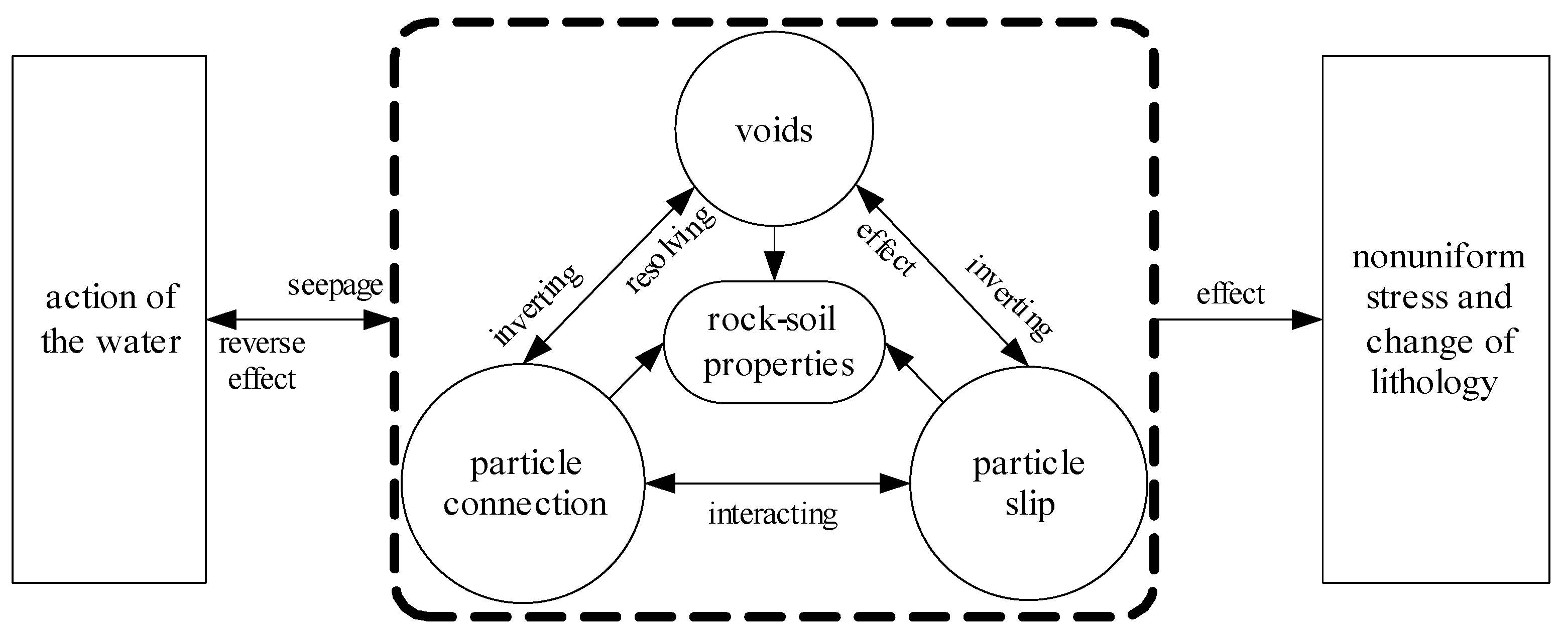
Rock and soil are complex discrete materials. The load-bearing capacity of rock mass depends on the continuous stability of its lithology and mechanical characteristics. As shown in
Figure 1, particles are the components of rock mass structure. In the initial state, the connection and distribution of particles determine the initial void size of rock and soil. This can affect the difficulty of subsequent sliding of particles. Under the penetration of water, water molecules move into the interior of rock and soil. They can cause a series of physical effects, such as the separation between particles and the increase in voids in the interior of rock and soil. The movement and loss of particles and the interference of buoyancy will inevitably produce uneven stress in the rock and soil. This is dynamic and randomly distributed. In addition, in the process of internal changes in rock and soil, there is a nonlinear feedback mechanism from beginning to end that constantly transits from non-equilibrium to equilibrium, thus driving the continuous change in lithology and negatively affecting the permeability of water. It can be seen that the infiltration of water into rock and soil is a process in which the mutual physical properties between water and rock and soil are changing. Each will finally reach its balance.
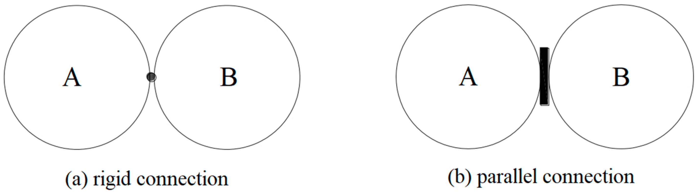
As shown in
Figure 2, there are two typical patterns of particle connections within soil and rock. Both particle A and particle B are skeleton particles of rock and soil, and do not undergo chemical reactions with water. For rock and soil with strong hydrophilicity, the internal skeleton particles are surrounded by a large number of clay minerals, and the connection between the two skeleton particles can be regarded as a parallel connection mode, while a small number of particles are in a rigid connection mode. When water seeps through the interior of the rock and soil, the spacing between particles inside the damaged rock and soil increases, and the original tightly connected state becomes loose. The detachment between particles increases the voids in the rock and soil, and the effect of water changes more significantly. Therefore, it can be seen that water plays a destructive role, causing alternating changes between solids and voids.
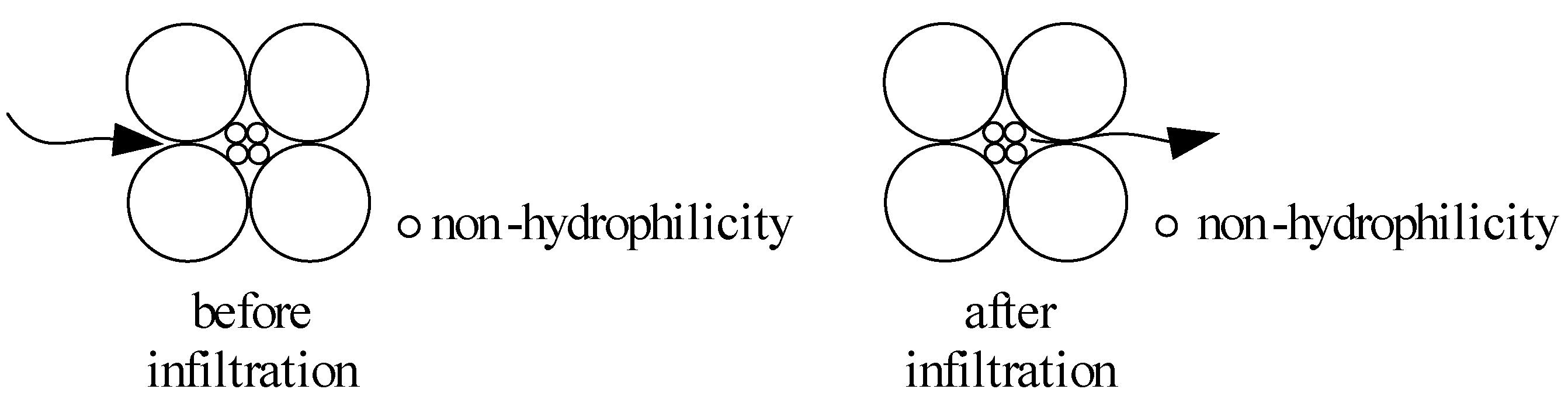
For different types of rock and soils, their internal grain composition is different. Comparing hydrophilic mineral particles with non-hydrophilic mineral particles, there is a great difference in the effect of the two on water permeability. As shown in
Figure 3, the rock and soil are filled with non-hydrophilic particles. In the process of water infiltration, it is similar to the arrows in the figure. If the water pressure is weak, the water will penetrate through the pores formed between the particles. There is almost no damage to the interior of rock or soil, and its initial void size basically determines that the water permeability remains unchanged. The connection mode between non-hydrophilic mineral particles can affect the overall compressive strength of rock and soil. The transmission of force between particles can jointly resist external loads. This type of rock and soil structure has good stability and can form a complete force chain inside.
For non-hydrophilic particles, only physical interaction can occur between water and particles. The seepage of water causes these particles to slide, be lost, or precipitate. For internal voids in rock and soil that have formed seepage channels, when these particles move into the channel, the seepage effect of water will be weakened. On the contrary, due to the scouring of these particles by water, the local voids in the rock and soil will increase, connecting the adjacent pores and increasing the seepage effect of water. Therefore, the seepage effect of water in rock and soil usually shows nonlinear variation characteristics until it finally tends toward a stable state.
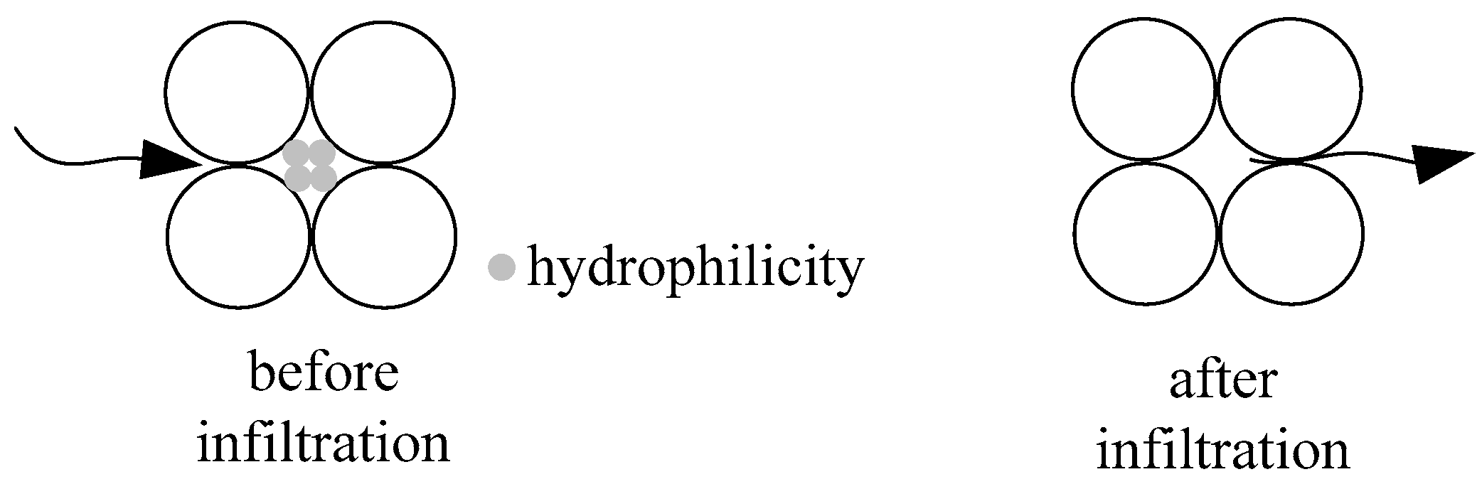
When there are hydrophilic clay minerals in the rock and soil, the skeleton particles play the main bearing role. They can be directly contacted or connected with the skeleton particles through the clay mineral particles. As shown in
Figure 4, arrows are process of water infiltration. Because clay mineral particles are easily hydrophilic and react with water chemically, they have a certain adsorption effect in the process of meeting water to strengthen water penetration. At the same time, water constantly erodes such particles, which changes their composition and reduces their viscosity. This causes the slip and loss of the particles. It can change the permeability of water in rock and soil.
It can be seen that in non-hydrophilic particles, water can flow around the particle boundary in the void formed by it. The internal structure of rock and soil remains unchanged. For hydrophilic particles, they have a certain adsorption effect on water. Due to the chemical reaction between the particles and water, there will be a temporary barrier to water infiltration in the adsorbed rock and soil. When clay mineral particles are damaged by water, the particles will slip and be lost. This will greatly reduce the water’s viscosity and increase the voids in the rock and soil. At this time, the permeability of water is very obvious, which is equivalent to water infiltration in rock and soil without hydrophilic mineral particles. In addition, considering the actual situation, the formation water encountered in engineering practice has certain height differences and flow velocity. Water pressure and flow rate are also principal factors affecting permeability. The greater the pressure difference and flow velocity formed at the infiltration and outflow, the better the mobility and permeability of water in the rock and soil. Therefore, the internal particle viscosity resistance of rock and soil, the pressure difference, and flow velocity of formation water are important factors. It is the key to analyze the internal force characteristics of rock and soil in the process of formation water infiltration.
3. Analysis of Water–Rock Interaction Mechanism in Seepage Process
At present, the permeability of rock and soil is mainly reflected in the following two points. First, there is basically no seepage into the pores, but water is stored by adsorption. The rock mass pores are the main channel of water flow, and the pores and fractures in the rock mass form a coupling system in the seepage. Second, both pores and fractures in the rock mass have a seepage effect, but this is only applicable to rocks with large porosity. The fracture network formed in the rock mass not only provides a channel for seepage but also can store a quantity of water.
3.1. Permeability Characteristics of Rock and Soil
The permeability of rock and soil is usually measured by the permeability coefficient. Darcy’s law is applied to the permeability process of rock and soil, and its expression is:
In the formula, is the permeability coefficient of rock and soil, is the total flow of water in the process of internal flow of rock and soil, is the cross-sectional area of rock and soil, is the permeability viscosity of water in rock and soil, and is the water pressure gradient. From Formula (1), it can be seen that there may be two situations regarding the permeability inside the rock and soil. One is that there is basically no seepage in the voids inside the rock and soil, only water storage. Rock and soil fractures are the main channels for water flow. This are due to their greater permeability than rock and soil pores. The internal fractures and pores of rock and soil form a coupling system in the process of seepage. Another situation is where both the internal pores and fractures of rock and soil have seepage effects, but this is only applicable to rocks and soils with high porosity. Usually, the fracture network formed within the rock and soil not only provides channels for seepage but also stores a portion of water.
The seepage action in a local area within the rock and soil is simplified as a plane problem for analysis. It is assumed that the skeleton particles are closely connected by clay minerals, and the water infiltration enters only from the
x direction. If the forces in the
x direction are balanced, the sum of the water seepage forces
is [
43]:
In the above formula, is the unit volume of the basin, p is the seepage pressure during the process of water flow, is the diameter of each different skeleton particle, and is the total number of skeleton particles. For the first item on the far right of the above formula, the negative sign represents the reaction force of particles on water, which is negative. The second is the force that the pressure gradient of water, which is constantly changing, is exerting on the skeleton particles. The pressure is continuously decreasing along the direction of action of the water, and the solid is also negative. Due to the seepage effect of water, the viscous force of water does negative work, resulting in loss of water flow. Therefore, the water pressure acting on the rock and soil particles is not hydrostatic pressure. The effective energy per unit weight of fluid is used to drive the fluid through porous media. This energy is lost due to viscous friction at the solid–liquid interface. When friction loses energy, there is always a resistance applied to the solid skeleton along the direction of motion.
It can be seen that the larger permeability coefficient and smaller the seepage viscosity of rock and soil, the greater permeability of formation and the stronger its permeability. However, for this kind of rock and soil, the degree of damage from water to their interior is relatively low. The water only passes around the rock and soil particles. For rock and soil with higher seepage viscosity, the permeability of water in the rock and soil is very slow. This is due to the large proportion of freshwater particles. In addition, some water will be stored, forming a situation where particles perform negative work on water, reducing its infiltration.
3.2. Damage Analysis of Internal Structure of Rock and Soil
Taking into account the action of movement in the process of water infiltration, tThe uneven water around the outer surface of the rock and soil particles drives the movement of the skeleton particles. This movement is uneven, and each particle is moving randomly. If only the average performance of all particles is considered, the momentum and continuous action equation of particles can be obtained as [
44]:
In the above formula, is the porosity in the rock and soil, and is the drag force of water by particles, which is a physical action that blocks the flow of water. There are two kinds of velocities implicit in the formula: the velocity of water flowing into the fracture , which is the absolute velocity, and , which is derived from Darcy’s law of permeability. This is usually obtained by dividing the velocity of water flowing through the rock mass by the flow area. From the above equation, it can be seen that the permeability exhibited inside the rock and soil is closely related to the velocity of water flow. The velocity of water affects the particle motion trajectory inside the rock and soil. The trajectory of particles is random and disorderly. They react on water, creating a certain resistance to it. Therefore, the coupling relationship between water and particles inside the rock and soil is mutually unified. The nonlinear dynamic feedback mechanism of water–rock interaction is ultimately manifested in how the energy is generated and evolves throughout the entire interaction process. Energy accompanies the process of changes in all systems, and the entire system is conserved before and after the changes occur.
With the continuous infiltration of water, when there is water pressure due to the seepage of rock and soil fissures, the expansion and lengthening of fissures will produce a complex deformation process. This will affect the permeability and the distribution of the internal structure of rock and soil. That is the seepage–stress coupling of rock and soil. Under the action of water and rock, the forces acting on the non-hydrophilic particles in the rock and soil are mainly the drag force
and the hydrostatic pressure
of water on the particles, whose comprehensive expression is:
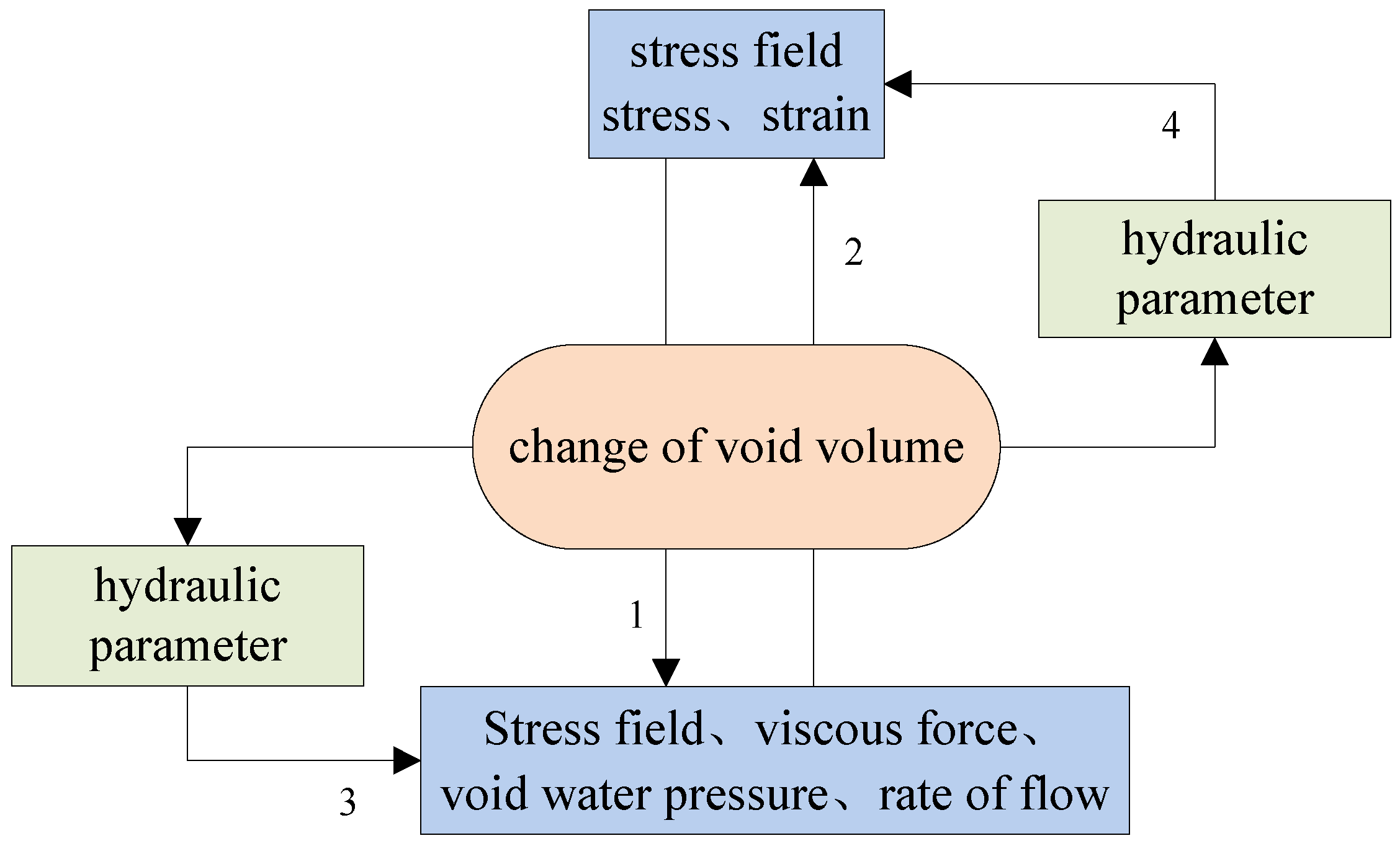
Through the above analysis, it can be seen that the complex interaction process between water and rock is summarized as the interaction mechanism of a complete fluid–solid coupling model (process 1 and 2 in
Figure 5). Through the interaction of water and rock, the porosity and permeability of the rock and soil are changing, which can reduce the effective stress of particles. The change in the void will cause a change in the cross-sectional area and water content of the medium, further affecting the mechanical parameters of soft rock, namely, processes 3 and 4. This indirect coupling process makes the coupling system present nonlinear characteristics.
For rock and soil, their internal structure includes solid particles and voids. The solid particles are further divided into skeleton particles and clay minerals. If the rock and soil are not damaged by water or external loads and maintain their own structure without any changes, the internal microstructure can be considered stable. The seepage effect of water causes continuous changes in the internal microstructure of rock and soil. There must be a certain correlation between solid and void inside the rock and soil. This determines the occurrence of rock and soil disasters and reduces the mechanical properties of the rock and soil.
3.3. Fractal Mechanism of Internal Structural Changes in Rock and Soil Seepage
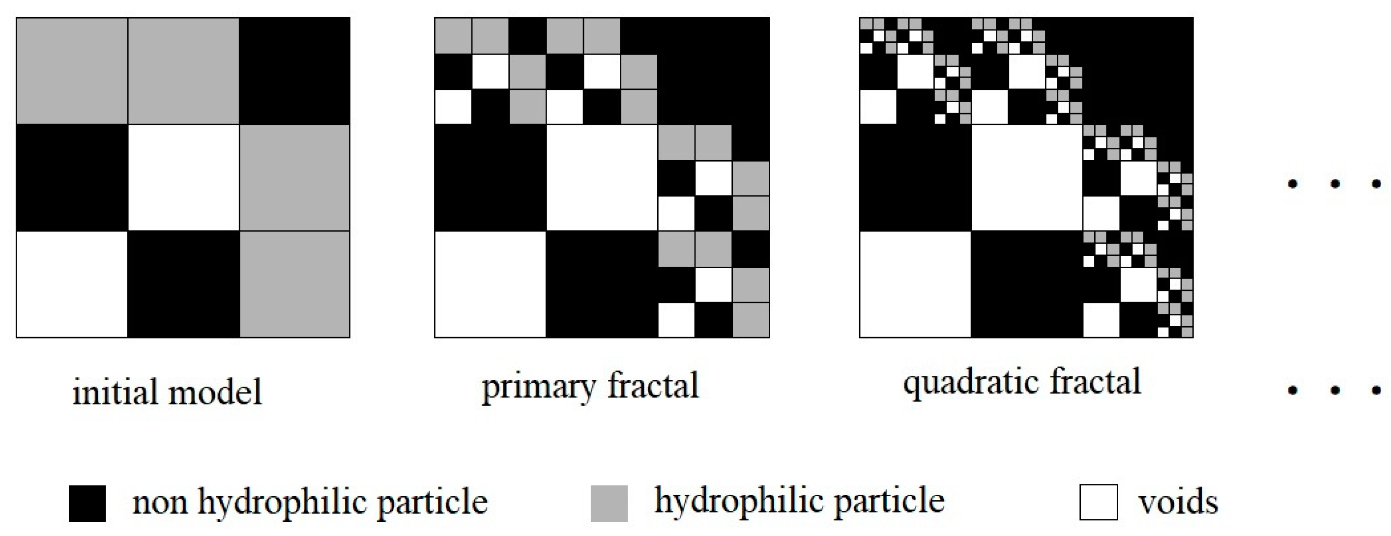
As mentioned earlier, the internal structure of rock and soil is composed of a combination of solids and voids. Under the action of water seepage, different changes in composition, arrangement, and other aspects occur between them. These are the behavioral characteristics of mutual transformation between the solid and the void. Based on the void solid fractal model, we further studied the internal correlation mechanism between solids and voids. The solid part inside the rock and soil is composed of skeleton particles and clay minerals that play a cementation role. During the continuous seepage process of water inside, the skeleton particles do not participate in the reaction. It is mainly the clay minerals inside that are constantly destroyed. Therefore, based on the ratio of the internal skeleton particles to the content of clay minerals, a model of the internal structure can be constructed, as shown in
Figure 6.
As shown in
Figure 6, there are non-clay particles, clay particles and internal voids in the rock and soil. Non-clay particles do not participate in the chemical reaction between water and rock, and are connected by clay particles. When water percolates in the rock and soil, the clay particles have good hydrophilicity, and these particles react with water chemically. Clay particles are destroyed, which further affects the connection between non-clay particles. However, the water–rock chemical action here is random and the fractal path is complex and changeable, resulting in uneven distribution of voids in the rock and soil. After several fractal actions, the degree of damage to clay particles is more serious: the bonding effect is weakened and the particles become smaller. In addition, some clay particles directly form non-clay particles after the initial chemical reaction with water. The rest of the clay particles continue to react with water, and the damage inside the rock and soil continues to deepen. It can be seen that after each fractal iteration, the solid and voids generated inside the rock and soil are retained and form a fractal set. The proportion of clay minerals is constantly decreasing, while voids are constantly increasing and forming various-sized pores. This also precisely indicates that as the seepage time of rock and soil increases, their internal porosity continues to increase. The dispersion and degree of damage from the pores become more complex.
4. Numerical Simulation Analysis of Water–Rock Permeability Effect
4.1. Rock and Soil Seepage Damage Mechanism
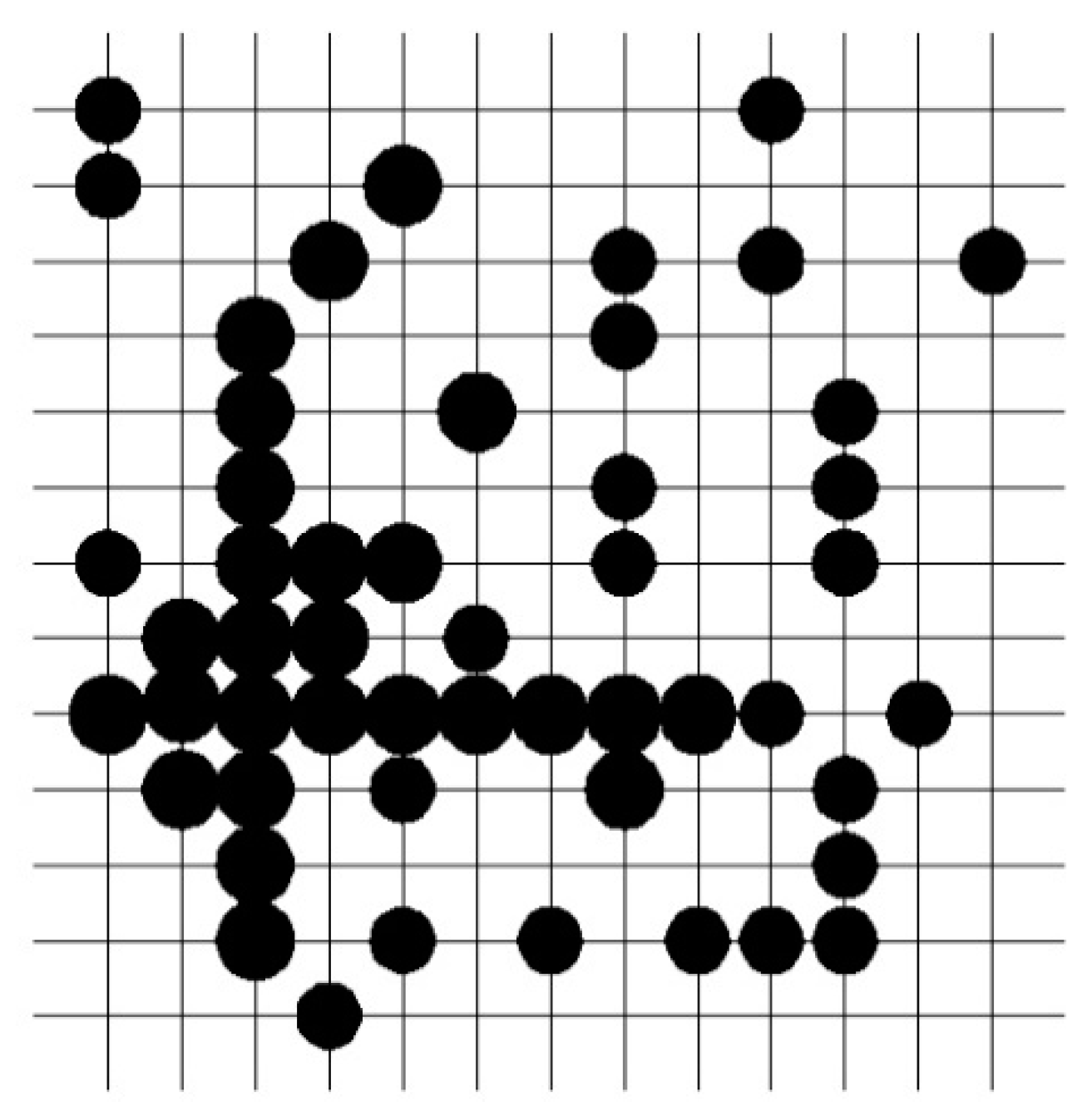
The water pressure difference formed before and after the seepage of water, as well as the voids or clay minerals formed inside the rock and soil, can result in a seepage effect between water and rock. The cracks and pores inside the rock and soil jointly provide a seepage channel for water–rock interaction. This can cause water to move in a randomly and disorderly fashion in various directions within the rock and soil and exhibit percolation characteristics.
As shown in
Figure 7, assuming that a black dot appears somewhere inside the rock and soil, the probability of the lattice at that point is p. These black dots are all collected into a certain part of the rock and soil through probability p. When the comprehensive analysis of this part reaches a certain threshold, its connectivity effect suddenly increases. This can cause a physical quantity inside the soft rock to undergo instantaneous mutations, jumps, and other behaviors. Among these, bond percolation and point percolation are the most common. In a certain network system, the keys connecting any two points in the network form a connection with a certain probability. At this point, compared to bond percolation, if this probability increases to a specific value, the interconnections within the network increase sharply. For point percolation, the occupancy probability of a certain point in the network is used as the research focus. After random action, if two adjacent points are occupied at the same time based on probability, this indicates that the area is connected. There is a random nonlinear change in the internal structural damage to the rock and soil. Therefore, the continuous effect of water pressure difference and the continuous changes in internal damage to rock and soil result in the continuous destruction of hydrophilic clay minerals. This will ultimately lead to a continuous water absorption process in the rock and soil.
4.2. Model Parameter
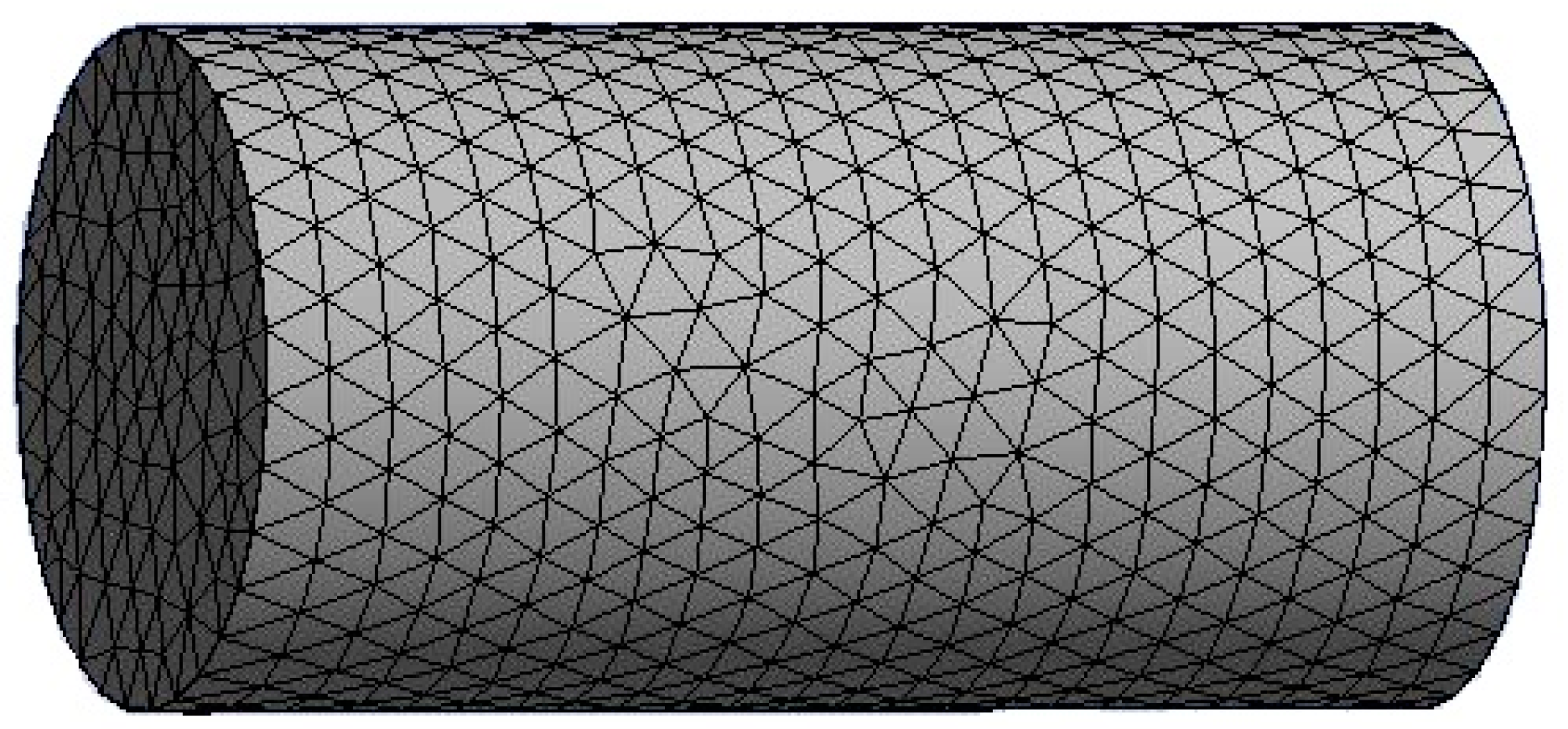
Fluent 17.0 finite element software is used for numerical simulation analysis. The rock sample of the geotechnical layer is taken as the simulation object. The rock sample is a cylinder with a bottom diameter of 0.2 m and a height of 0.8 m. During the simulation, it is assumed that one bottom is the inlet and the other is the outlet. During the whole simulation process, the water velocity at the inlet is kept constant, and the changes in relevant physical parameters between water and rock during the whole infiltration process are analyzed. In order to form a comparative analysis, rock and soil with different viscosity resistance coefficients are selected for simulation. Other initial conditions, including initial damage, void ratio, internal structure characteristics, are the same. Relevant parameters are shown in
Table 1. Model S1 and model S2 have the same initial density, so the initial porosity of the two models is the same. In two different geotechnical models, even though the total volume of the particles constituting the soil is the same, the clay mineral particles are quite different. The number of clay mineral particles usually determines the viscous resistance and inertial resistance of water in rock and soil. Therefore, for comparative analysis, model S1 is identified as having a smaller viscous resistance coefficient and inertial resistance coefficient. The model is similar in that there is less clay mineral composition in the rock and soil. Model S2 is identified as having large viscous resistance coefficient and inertial resistance coefficient. The model is similar in that there are more clay minerals in the rock and soil.
In addition, only the boundary conditions of the inlet and outlet are considered in the model. The flow velocity at the inlet and outlet is 0.15 m/s. The turbulence intensity of water is set to 5%. For the strength and hydraulic diameter of water, in order to ensure that water can cover the whole model, the hydraulic diameter is set as 0.25 m.
4.3. Modeling and Solving
The core solid model is established by Fluent, and the elements are divided by triangular free mesh. The total number of elements is 19,606, and the number of nodes is 5861. The finite element model is shown in
Figure 8.
In this model, boundary conditions are set at both ends of the core. The left end is the inlet, the flow rate remains unchanged, and the right end is the outlet. During the solving process, relevant parameters can be set for monitoring. The whole solving process is set to 500 time steps. For each step toward the solution, the software records and stores the relevant parameters until the final solution is completed.
5. Results Analysis
According to the results of the numerical model, the solved permeability coefficient, the mass flow velocity at the entrance and exit, and the pore water pressure inside the rock and soil are selected for discussion. The variation rules for the physical quantities of the water–rock interaction are analyzed.
5.1. Variation Law of Permeability Coefficient of Rock and Soil
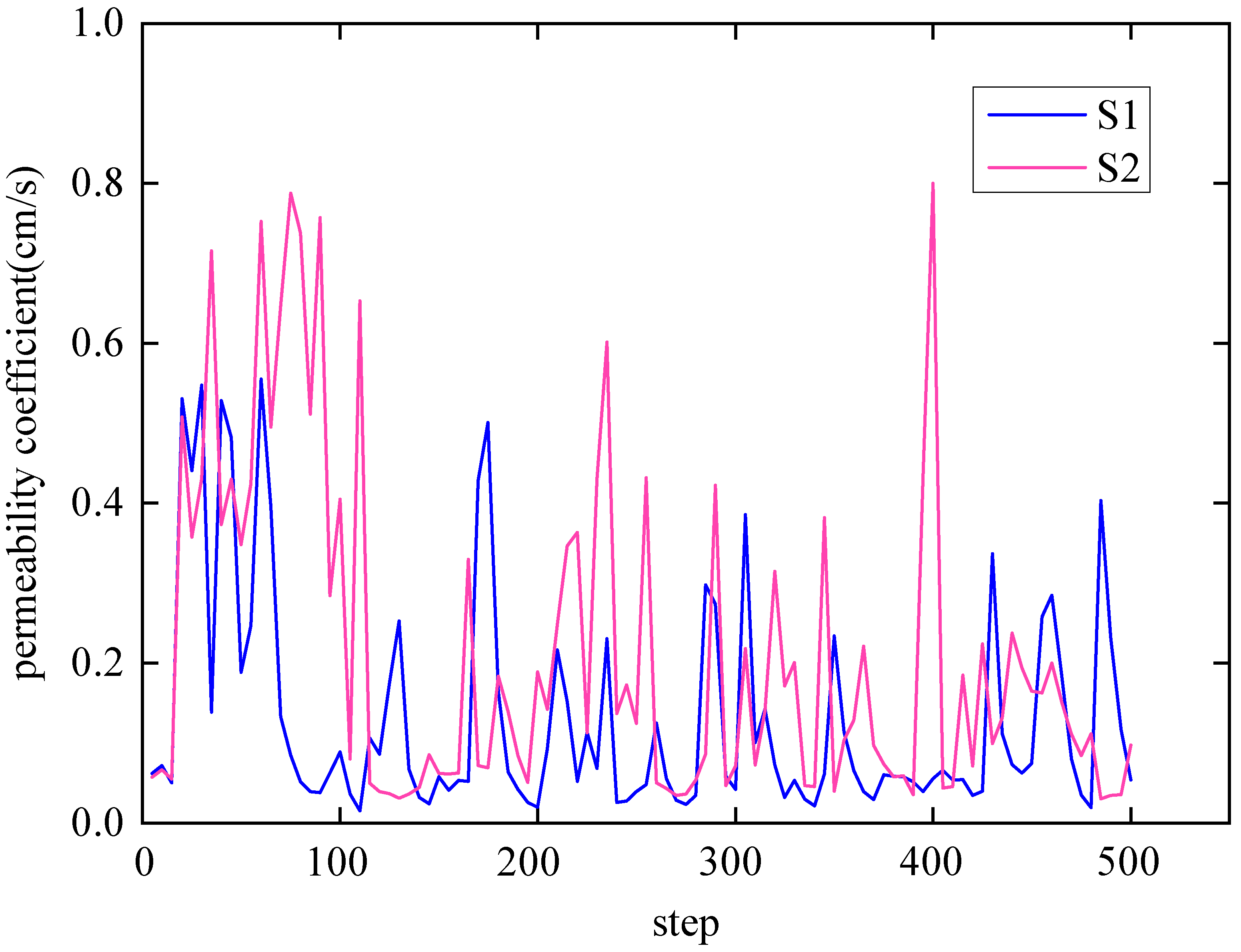
As shown in
Figure 9, with the continuous deepening of formation water infiltration, its permeability coefficient presents a disorderly mutation, and the nonlinear characteristics are extremely obvious. There is no much difference between high-cohesive-resistance geotechnical particles and low-cohesive-resistance geotechnical particles. It can be seen that the change in the internal composition of rock and soil is random. Under different time steps, the permeability coefficient of rock and soil exhibits disorderly fluctuations. This change pattern is the result of the random fractal evolution of the internal structure of rock and soil during the seepage process. It is related to the internal damage mechanism of rock and soil in
Figure 6. The fluctuation in the permeability coefficient is further explained below.
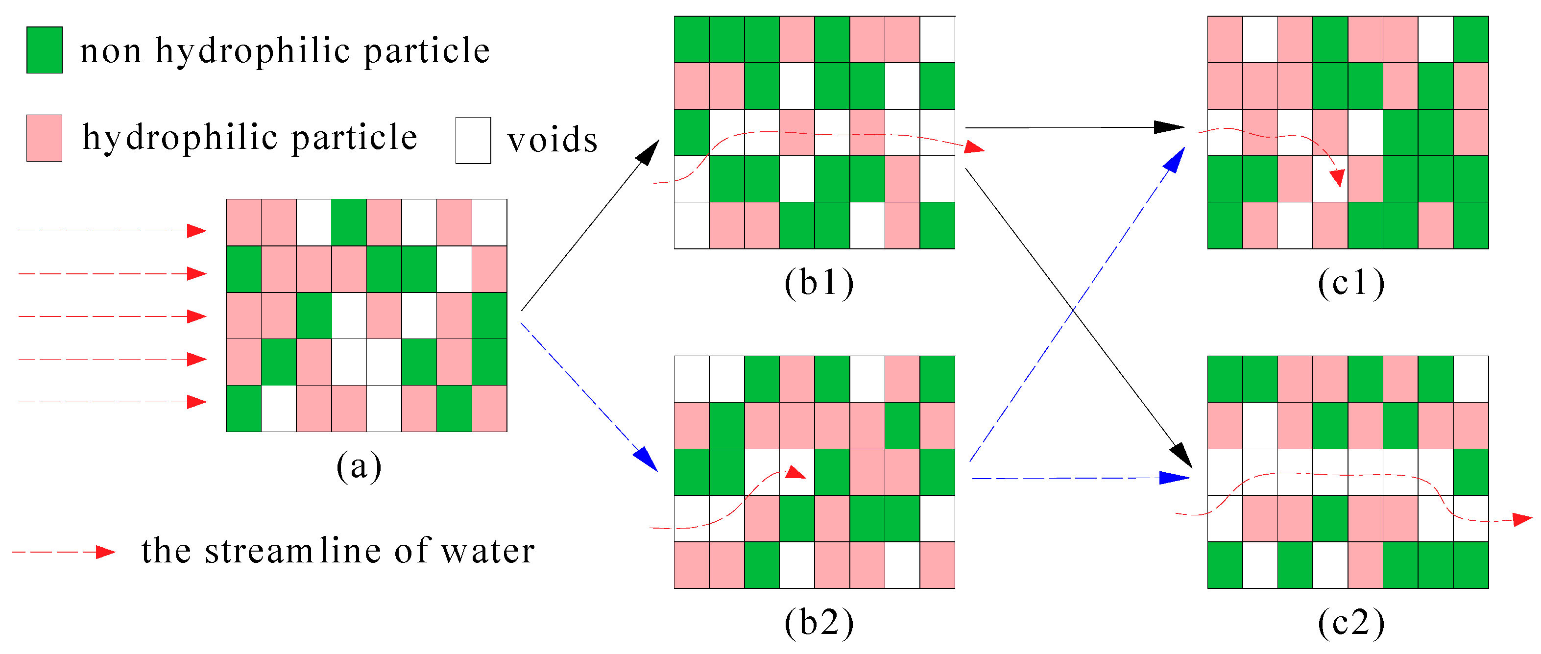
As shown in
Figure 10, rock and soil with hydrophilic minerals are taken as an example. The (a) to (c) parts of the figure represent a series of possible changes in the internal structure of the rock and soil during the process of water seepage. At the beginning of water seepage, it is assumed that (a) is the initial internal structural arrangement of the rock and soil, and there are initial damages and some hydrophilic minerals that absorb water easily. After a period of seepage, the internal structure of the rock and soil in the same area changes. One possibility is that, as shown in (b1), hydrophilic particles undergo chemical reactions with water or are destroyed by physical interactions. The voids increase and form favorable channels. At this point, the seepage effect becomes apparent. Another possibility is that, as shown in (b2), although some hydrophilic particles are damaged, non-hydrophilic particles from other regions will merge and form a closed arrangement during the flow and erosion of water. At this point, further seepage of water is hindered, which will reduce the permeability coefficient of the rock and soil. With the further action of seepage, the original permeability coefficient increases (b1). After the particles inside the rock and soil are rearranged again, the permeability effect may be weakened (c1) or become more obvious (c2).
Similarly, for non-hydrophilic rock and soil, although the particles inside the rock and soil will not be damaged, water still has a physical effect on the particles. It can cause them to undergo uncertain random behaviors, such as flow, slip, and rotation. The random variation of these particles causes the seepage channels inside the rock and soil to sometimes close and sometimes open. This continuous and repeated action continues, which can result in fluctuations in the permeability coefficient of the rock and soil at different time steps.
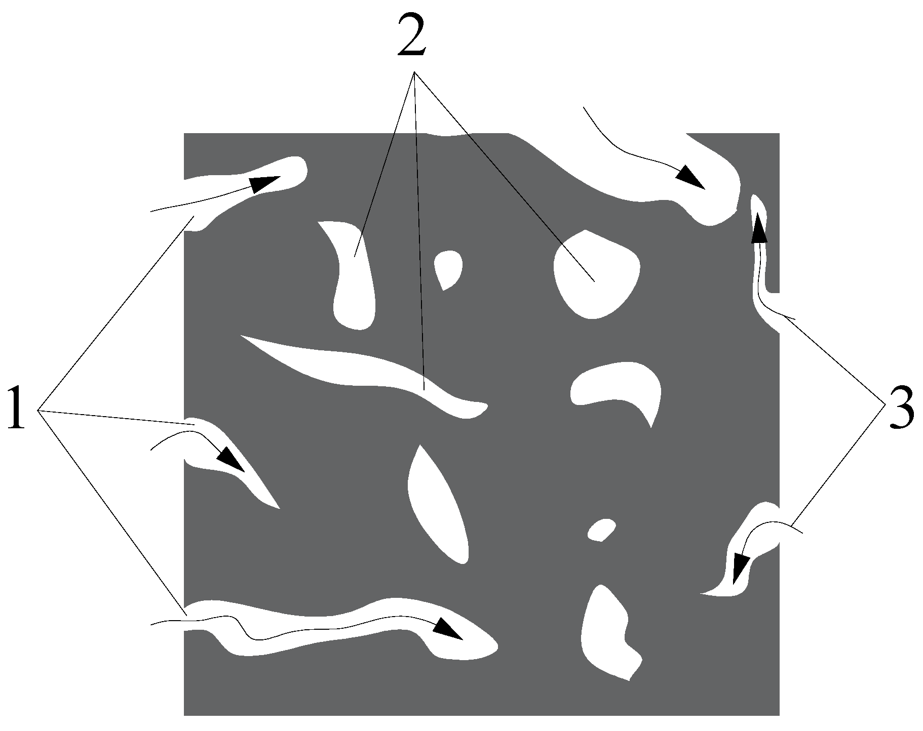
In addition, based on the open and closed pores inside the rock and soil, the nonlinear characteristics of water inside the rock and soil can be further explained. As shown in
Figure 11, arrows are the penetration of water. Taking the local pores inside the rock and soil as an example, when water passes through open pores, its flow becomes smoother and its seepage effect becomes more pronounced. At this point, the arrangement of the internal structure of the rock and soil provides a very convenient channel for water seepage. However, for closed pores, water cannot directly enter the pores. During this process, water reacts chemically with clay particles that form closed pores, continuously damaging the internal structure of the rock and soil. At this point, for closed pores, the seepage effect of water slows down. It can be seen that at the same time, different positions within the rock and soil have different seepage effects, which together determine the nonlinear seepage characteristics of the rock and soil.
5.2. Change Law of Water Mass Flow Rate
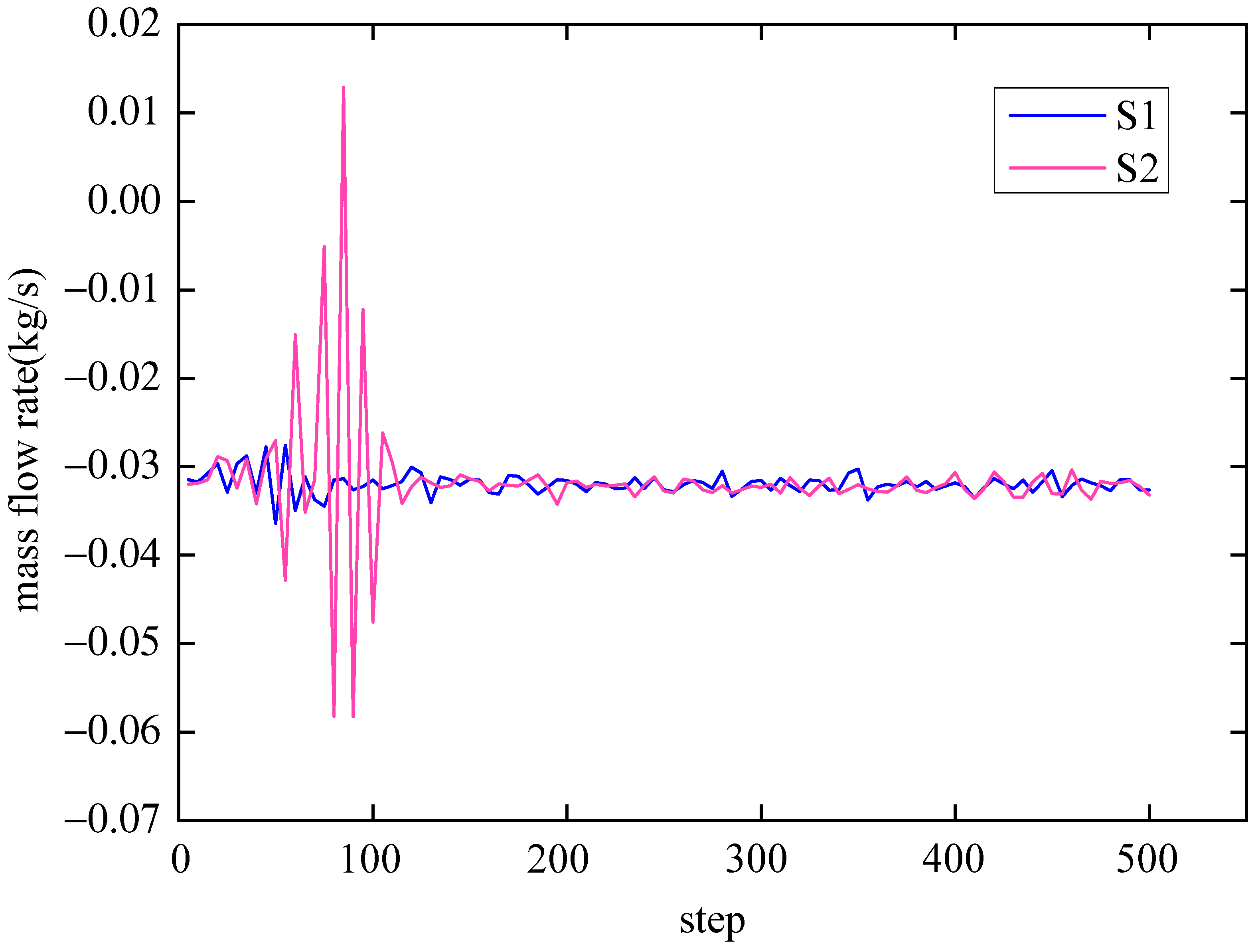
Here, the mass flow rate of water at the outlet of the rock sample is taken as the whole seepage process to discuss the change rule of water.
As shown in
Figure 12, the mass flow rate fluctuates greatly in the initial stage of infiltration, especially for rock and soil with high cohesive resistance. It can be seen that the hydrophilic mineral particles of this kind of rock and soil are largely damaged in the initial stage. With continuous infiltration, the mass flow rate tends to be flat. It can reach a certain balance around −0.03 kg/s with negative resistance and in a closed state. Therefore, for the rock and soil with hydrophilic particles, when the water penetration time is longer, the damage to the particles becomes more obvious. Non-hydrophilic mineral composition increases in the interior, which is similar to approaching low-cohesive-resistance rock and soil. They all present similar nonlinear characteristics.
5.3. Distribution Law of Water Pressure in Rock and Soil
A comprehensive analysis is carried out on low-cohesive-resistance rock and soil and high-cohesive-resistance rock and soil. These represent the distribution nephogram of pore water pressure under different steps of formation water infiltration in rock and soil.
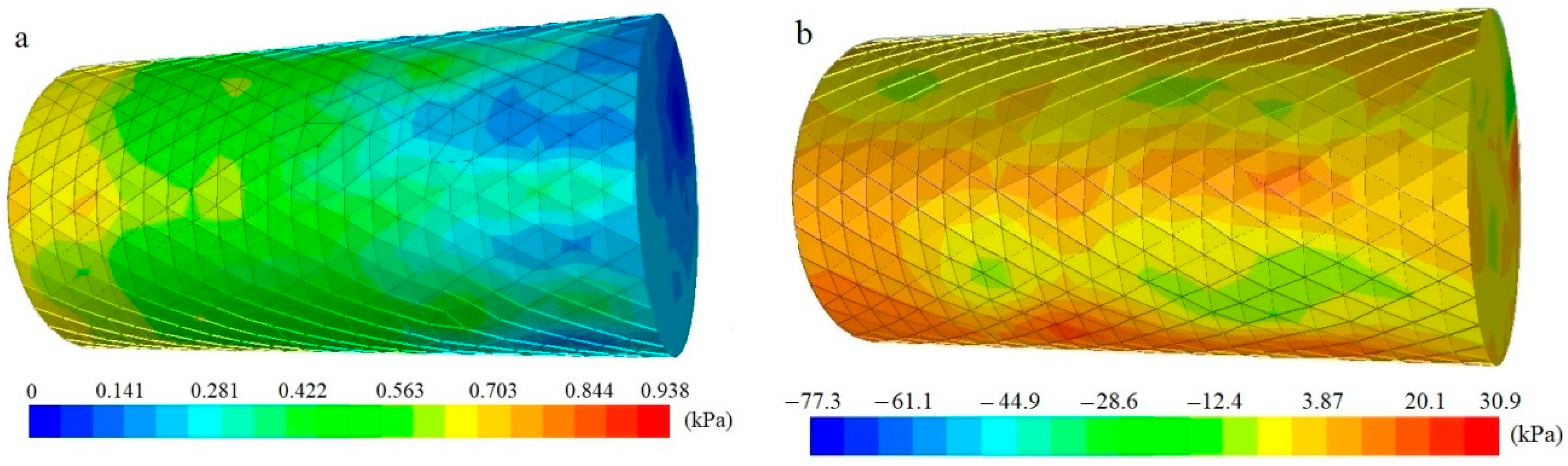
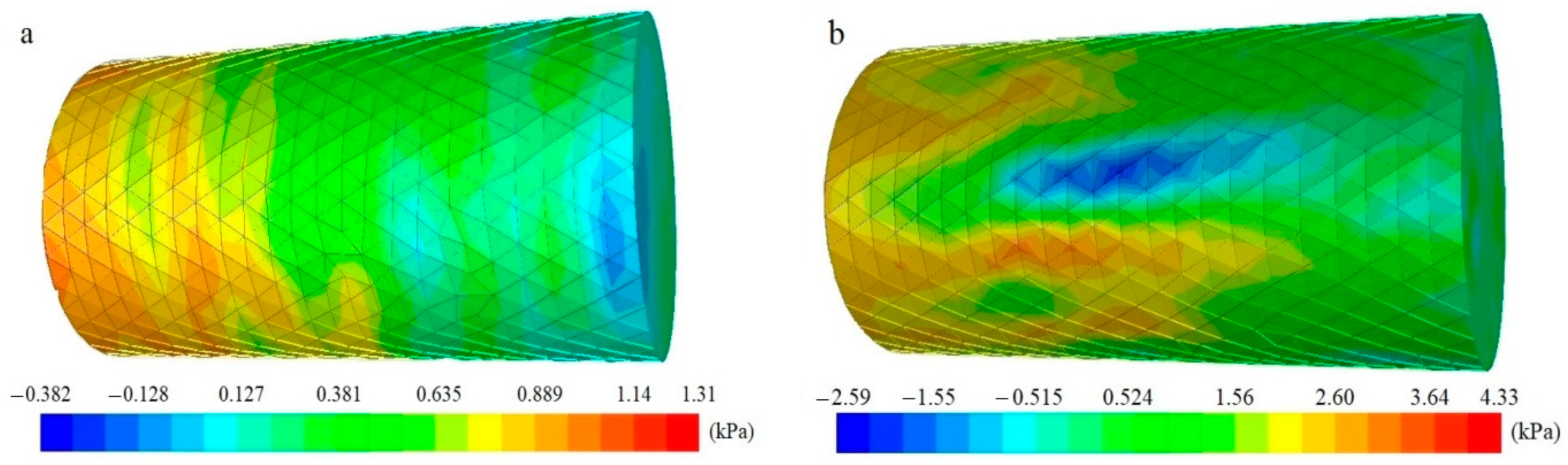
In the initial stage of water infiltration, the pore water pressure is randomly distributed in the rock and soil and there is no negative resistance, which indicate that the initial infiltration effect of water is good (as shown in
Figure 13). With the continuous action of seepage, negative pore water pressure appears in the rock and soil. Due to the presence of viscous substances, there is a certain resistance to water penetration and the penetration process slows down (as shown in
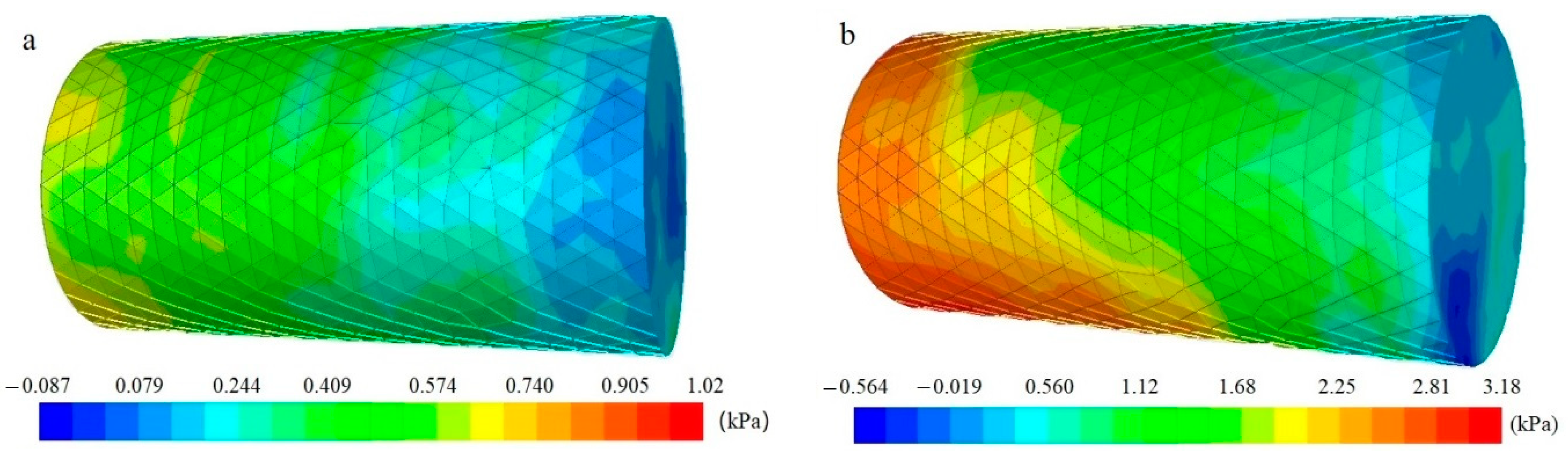
Figure 14). At this time, more water and clay minerals will participate in relevant chemical reactions, destroying hydrophilic particles. However, with the increase in infiltration time, the negative pore water pressure decreases and the permeability effect increases after most clay particles are destroyed (as shown in
Figure 15).
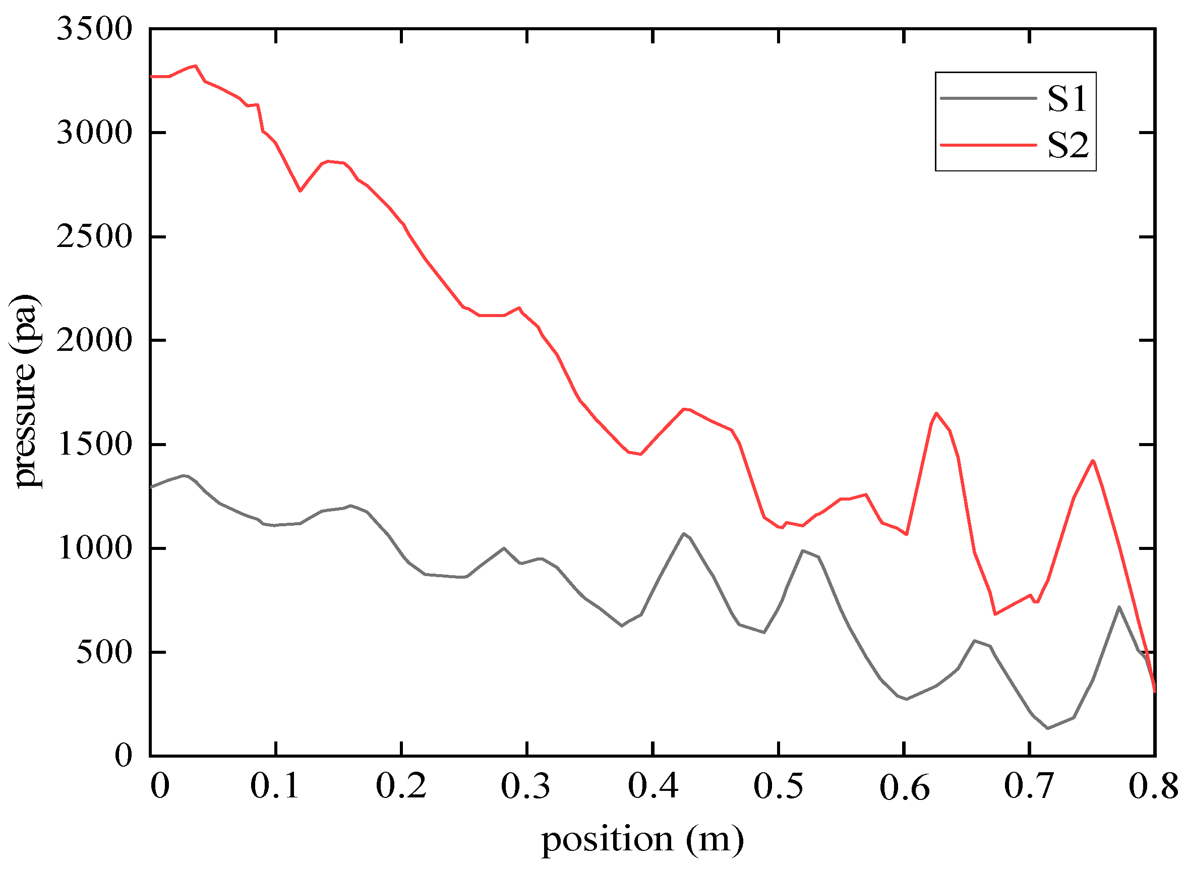
As shown in
Figure 16 below, the pressure-drop difference curve changes at different locations from the rock sample to the inlet. For low-cohesive-resistance rock and soil minerals, the pressure-drop difference from the infiltration point to the outlet point shows a slow downward trend. For high-cohesive-resistance rock and soil minerals, the pressure-drop difference changes very quickly, and the pressure-drop difference curve has a large slope. It can be seen that the degree of damage to low-cohesive-resistance rock and soil minerals by water is relatively small, and the flow of water in the rock mass is relatively balanced. However, in the early stage of water infiltration, rock and soil particles with high viscosity will absorb water for storage. This can greatly reduce the water-permeability effect and form a great pressure-drop difference in the early stage. With the prolongation of infiltration time, these particles are constantly destroyed, and the permeability of water becomes progressively easier. The water finally forms a stable flow in the rock mass.
It can be seen from the above analysis that water first seeps into the interior from the microfracture and micropore channels of rock and soil. Through the continuous water absorption of hydrophilic clay minerals in the rock and soil, the permeability effect of water is changed. The internal degree of damage to rock and soil is increasing. Microfissures and micropores of rock and soil continue to expand. As a result, the microstructural damage to rock and soil increases, and the clay mineral layer is damaged and loses its cementation. The geological problems encountered in practical engineering are often due to the continuous effect of this behavior, which eventually forms the intersecting and penetrating cracks inside the rock mass and reduces the bearing capacity of the rock mass.
5.4. Analysis of the Mechanism of Internal Particle Changes in the Permeability Effect of Rock and Soil
Here, a specific analysis will be conducted on the internal particle structure changes after the seepage effect of rock and soil to further explore its internal damage mechanism. Relevant research has shown that both hydrophilic and non-hydrophilic particles exhibit mechanical damage behaviors such as deposition, transport, detachment, pore drainage, and weakened cementation during water infiltration. Among these, the most important diagenetic process that allows rock and soil to exhibit good mechanical properties is cementation, which determines the compressive strength of the rock and soil.
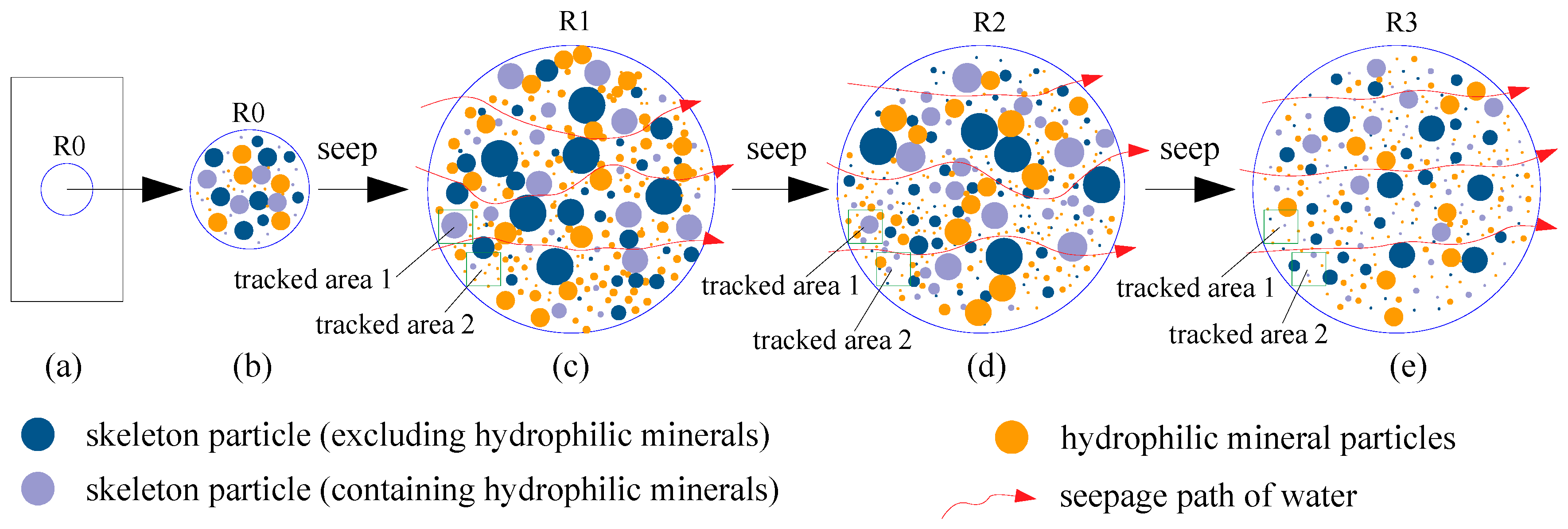
Figure 17 depicts the damage process of particles in rock and soil, wherein (a) is the initial rock sample, and R0 in a certain area is extracted for detailed analysis. Area R0 in the figure is a whole composed of skeleton particles and clay minerals. After damage in region R0, some clay particles in the outer layer begin to fall off. The original large particle set R0 has become a smaller particle set R1, and the connection between particles has become loose, as shown in (c). Under the continuous infiltration of water, the connection between particles continues to be destroyed, and the previously formed particle set R1 disintegrates, as shown in (d) and (e). They become smaller particle sets—R2 and R3. Therefore, the aggregates continue to disintegrate and become smaller, and finally only skeleton particles and a small amount of clay minerals remain in the rock and soil.
It can be seen that the different damage caused by the particles in rock and soil are the root of the final collapse and disintegration of the rock mass. The interaction mechanism between the particles is reflected in the law of different degrees of damage to rock and soil at the mesoscale.
6. Comparative Analysis of Numerical Simulation and Experiment
Based on the analysis and comparison of numerical simulation results with existing experimental research results, this article will further explain the degree of structural damage and nonlinear characteristics of the rock and soil seepage process.
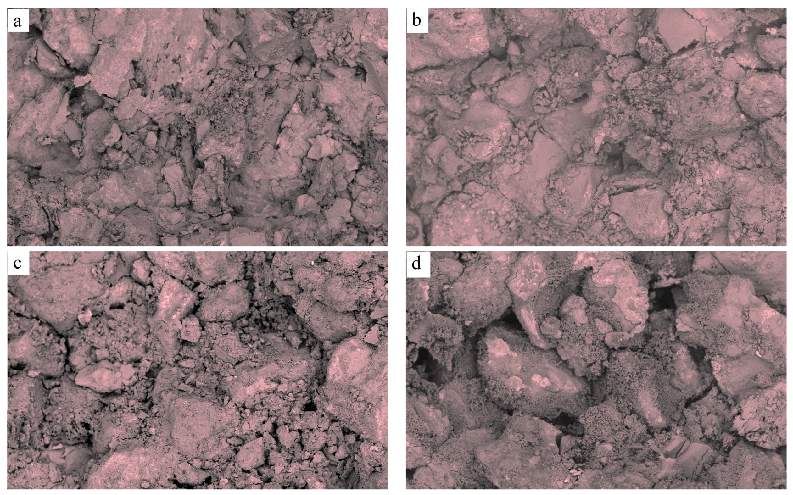
As shown in
Figure 18, the authors take soft rock as the research object and analyze the degree of internal damage to soft rock under the infiltration of water. From (a) to (d), it can be seen that the rock sample area specified in the figure is analyzed. The area begins in a fully integrated state, and after water infiltration, its interior continuously decomposes, which can increase the degree of damage. As the seepage time increases, the effect of subsequent damage changes decreases. According to the experimental results, it can be concluded that due to the large number of hydrophilic particles present in soft rocks, water can undergo chemical reactions with these particles during the seepage process. This will disrupt the connection between the internal particles in the rock sample. Therefore, at the beginning of seepage, the degree of damage inside the rock sample is significant. With the continuous action of seepage, a large number of hydrophilic particles have been destroyed, and non-hydrophilic particles are independent of each other and form channels for water flow. At this time, water flows through the internal pores, and the degree of damage to the structure gradually weakens. The experimental results are consistent with the numerical simulation in this article, indicating the internal random damage variation mechanism of water–rock seepage.
7. Conclusions
This article uses theoretical analysis and numerical simulation methods to study the nonlinear behavior characteristics of water inside rock and soil. It explores the coupling effect and coordination mechanisms between water and rock. Finally, the research value and explanatory power of this article are highlighted. The main conclusions are as follows.
- (1)
The permeability of formation water can cause a certain degree of damage to the internal structure of rock and soil. In the initial stage of seepage, water significantly damages the hydrophilic particles inside the rock and soil, which can lead to a sharp increase in damage inside the rock and soil. As the seepage continues, the hydrophilic particle composition inside the rock and soil decreases significantly, and the water seepage tends to stabilize.
- (2)
During the seepage process, the permeability coefficient of the rock and soil exhibits strong nonlinear changes, with many sudden changes that can reflect the dynamic characteristics of internal structural changes in the rock and soil. A series of behaviors, such as particle rotation, sliding, and clay mineral failure, are the root causes of changes in geotechnical properties. The mechanical behavior of particles inside rock and soil is a concentrated manifestation of their random fractal and infiltration strength. Seepage will ultimately lead to continuous protrusion and jumping of the rock and soil permeability. This is an extremely irregular behavioral characteristic, which indicates that the interior of the rock and soil is undergoing rapid damage.
- (3)
The pore water pressure of rock and soil exhibits a non-equilibrium variation pattern. The overall trend is that the infiltration effect becomes more pronounced. A complete fluid–structure interaction system is formed between water and rock, and the two are coordinated and unified. Pore water pressure forms local stress concentration in different areas within the rock and soil. It can accelerate the generation and expansion of pores in that area. The state is changing from non-equilibrium to equilibrium between water and rock and soil.
The research results of this article have important reference value for the problem of rock and soil disasters, especially for the study of correlation between scales, as well as the quantitative characterization of random damage and nonlinear characteristics within rock and soil.
Author Contributions
Data curation, N.L. and Z.W.; formal analysis, N.L.; methodology, N.L.; project administration, N.L.; writing—original draft, N.L. and Z.W.; writing—review and editing, Z.W. All authors have read and agreed to the published version of the manuscript.
Funding
This research was funded by the Guangxi Science and Technology Base Talent Project (Guike AD21220126), the Basic Ability Enhancement Program for Young and Middle-Aged Teachers of Guangxi (2021KY0358), and the Guangxi University of Science and Technology Doctoral Fund Project (Xiaokebo21z53), and the Guangxi Science and Technology Department project and the Guangxi Education Department project.
Data Availability Statement
Data are contained within the article.
Conflicts of Interest
The authors declare no conflicts of interest.
References
- Klungtvedt, K.R.; Saasen, A. A method for assessing drilling fluid induced formation damage in permeable formations using ceramicdiscs. J. Pet. Sci. Eng. 2022, 213, e110324. [Google Scholar] [CrossRef]
- Eltom, H.A.; Al-Mahfoudh, A.E.; Kusuma, L. Geological understanding of permeability upscaling in mixed carbonate siliciclastic reservoirs: An outcrop approach, Miocene Dam formation, eastern Saudi Arabia. Geoenergy Sci. Eng. 2023, 223, e211559. [Google Scholar] [CrossRef]
- Hua, W.; Li, J.X.; Dong, S.M.; Pan, X. Experimental Study on Mixed Mode Fracture Behavior of Sandstone under Water-Rock Interactions. Processes 2019, 7, 70. [Google Scholar] [CrossRef]
- Chen, K.; Liu, Q.M.; Yang, T.T.; Ju, Q.D.; Feng, Y. Statistical analyses of hydrochemistry in multi-aquifers of the Pansan coalmine, Huainan coalfied, China: Implications for water-rock interaction and hydraulic connection. Heliyon 2022, 8, e10690. [Google Scholar] [CrossRef] [PubMed]
- Pavazdavani, M.; Movaghar, M.R.K.; Dehghani, S.A.M. Low salinity water flooding: Evaluating the effect of salinity on oil and water relative permeability curves suing coupling of DLVO and geochemical reactions. J. Pet. Sci. Eng. 2022, 215, e110677. [Google Scholar] [CrossRef]
- Shabani, A.; Kalantariasl, A.; Parvazdavani, M.; Abbasi, S. Geochemical and hydrodynamic modeling of permeability impairment due to composite scale formation in porous media. J. Pet. Sci. Eng. 2019, 176, 1071–1081. [Google Scholar] [CrossRef]
- Yakovlev, G.; Grokhovsky, V. Application of Water-rock Interaction to Structural Changes of Iron Meteorites in Terrestrial Conditions. Procedia Earth Planet. Sci. 2017, 17, 542–545. [Google Scholar] [CrossRef]
- Phan, T.T.; Vankeuren, A.N.P.; Hakala, J.A. Role of water-rock interaction in the geochemical evolution of Marcellus Shale produced waters. Int. J. Coal Geol. 2018, 191, 95–111. [Google Scholar] [CrossRef]
- Negrel, P.; Pauwels, H.; Chabaux, F. Characteerizing multiple water-rock interactions in the critical zone through Sr-isotope tracing of surface and groundwater. Appl. Geochem. 2018, 93, 102–112. [Google Scholar] [CrossRef]
- Zhang, Y.L.; Sui, H.T.; Yang, L.; Lin, R.F. An Experimental Investigation on the Shear-Seepage Coupling Failure Behavior of Split Grouting-Reinforced Body. Processes 2023, 11, 2704. [Google Scholar] [CrossRef]
- Liu, T.T.; Yu, Q.C. Experimental investigation into the permeability of water vapor in shales. J. Hydrol. 2022, 609, e127697. [Google Scholar] [CrossRef]
- Jin, L.; Zeng, Y.W.; Cheng, T.; Li, J.J. Seepage clogging characteristics of rock and soil porous media using LBM-IMB-DEM simulation method. Chin. J. Geotech. Eng. 2021, 43, 909–917. [Google Scholar]
- Xiao, Z.Y.; Wang, C.S.; Wang, G.; Jiang, Y.J.; Yu, J.H. Influences of matrix-fracture interaction on permeability evolution: Considering matrix deformation and stress correction. Chin. J. Geotech. Eng. 2021, 43, 2209–2219. [Google Scholar]
- Jia, Q.L.; Xiang, L.T.; Yu, M.; Deng, X.; Zhao, Z.H.; Li, C.S.; Chen, H.L. Scale effect of permeability variation pattern of fracture-karst media. J. Arid Land Resour. Environ. 2022, 36, 127–134. [Google Scholar]
- Duan, L.L.; Deng, H.F.; Xiong, Y.; Zhi, Y.Y.; Pan, D.; Qi, Y. Study on the Influence of Morphology of Rock Mass Fracture Surface on Its Seepage Characteristics. J. Disaster Prev. Mitig. 2021, 41, 110–117. [Google Scholar]
- Kang, K.; Wang, Z.Z.; Dong, P.; Liu, B.; Liu, Q.H.; Cao, L.S. Inversion Analysis of Surrounding Rock Permeability Coefficient and External Water Load of Shield Tunnel in Complex Stratum with High Groundwater Table. J. Water Resour. Archit. Eng. 2022, 20, 35–41. [Google Scholar]
- Wu, G.J.; Chen, W.Z.; Tan, X.J.; Dai, Y.H. Effect of the permeability dynamic evolution of saturated rock on the stability of diversion tunnels. Chin. J. Rock Mech. Eng. 2020, 39, 2172–2182. [Google Scholar]
- Cui, S.D.; Guo, S.T.; Dai, Y.Q. Determination Method of Anisotropy Permeability Coefficient for Underground Water Sealed Cavern in Sandstone Area and Its Application. Mod. Tunn. Technol. 2019, 56, 65–69. [Google Scholar]
- Kong, H.L.; Wang, L.Z. The Mass Loss Behavior of Fractured Rock in Seepage Process: The Development and Application of a New Seepage Experimental System. Adv. Civ. Eng. 2018, 2018, 7891914. [Google Scholar] [CrossRef]
- Wang, Z.J.; Li, Z.; Lu, L.; Liu, Y.R. Study on the Distribution Law of Permeability Coefficient of Surronding Rock Based on Seepage. Chin. J. Undergr. Space Eng. 2018, 14, 619–624. [Google Scholar]
- Huang, Y.; Zhou, L.T.; Zhou, Z.F. Equations for Permeability Variation of Fractured Rock Mass under High Water Pressure. J. Eng. Geol. 2018, 26, 1433–1438. [Google Scholar]
- Chen, P.P.; Bai, B. Simulation of seepage problems in unsaturated soil using the smoothed particle hydrodynamics (SPH) method. Chin. J. Rock Mech. Eng. 2016, 35, 2124–2130. [Google Scholar]
- Wang, J.G.; Jin, Q.; Liang, B.; Liu, W.F. Creep features and the creep model of the rock and soil variable parameters under the impact of the seepage pressure in the creep process. J. Saf. Environ. 2016, 16, 120–125. [Google Scholar]
- Yang, Y.R.; Li, W.P.; Wang, Q.Q. A study of the relationship between the coefficient of permeability and microstructure of the Pliocene laterite. Hydrogeol. Eng. Geol. 2020, 47, 153–160. [Google Scholar]
- Li, Y.S.; An, N.; Zhao, B.; Zhang, Z.N. Damage-Induced Seepage Model for Jointed Rockmass. Sci. Technol. Eng. 2020, 20, 1780–1785. [Google Scholar]
- Sheng, J.L.; Han, Y.F.; Ye, Z.Y.; Cheng, A.P.; Huang, S.B. Relative permeability model for water-air two-phase flow in rough-walled fractures and numerical analysis. Rock Soil Mech. 2020, 41, 1048–1055. [Google Scholar]
- Wang, W.M.; Wang, X.J.; Zhang, W.S.; Tiao, Z.X. Analysis of deformation parameter and permeability coefficient of single fractured heterogeneous rock mass. J. Huazhong Univ. Sci. Technol. (Nat. Sci. Ed.) 2018, 46, 40–45. [Google Scholar]
- Cao, X.S.; E, L.S.; Lai, X.Y.; Zhou, S.; Li, G.W.; Yuan, J.P.; Wu, J.T. Factors for strength attenuation of mudstone during slaking and disintegration. Chin. J. Geotech. Eng. 2019, 41, 1936–1942. [Google Scholar]
- Liang, B.; Li, R.C.; Jiang, L.G.; Dong, Q. Experimental study on mineral composition of sedimentary rock and influence of durable disintegration. Coal Sdcience Technol. 2018, 46, 27–32. [Google Scholar]
- Keppert, M.; Zumar, J.; Cachova, M.; Konakova, D.; Svora, P.; Pavlik, Z.; Vejmelkova, E.; Cerny, R. Water Vapor Diffusion and Adsorption of Sandstones: Influence of Rock Texture and Composition. Adv. Mater. Sci. Eng. 2016, 2016, 8039748. [Google Scholar] [CrossRef]
- Cao, L.L.; Zhang, P.; Zhang, J.Z.; Lin, G.; Jiskani, I.M.; Chen, Z.Q.; Wang, Z.F.; Li, M. Experimental Study of Hysteresis Characteristics of Water-Sediment Mixture Seepage in Rock Fractures. Geofluids 2021, 2021, 6692388. [Google Scholar] [CrossRef]
- Chen, Z.M.; Zhao, J.W.; Gong, J.; Chen, Y.F.; Li, Z.Y.; Sun, S.Q. Softening and Disintegration Characteristics of Soft Rock Swelling Rocks. Sci. Technol. Eng. 2022, 22, 5358–5365. [Google Scholar]
- Del Greco, O.; Ferrero, A.M.; Oggeri, C. Experimental and analytical interpretation of the behaviour of laboratory tests on composite specimens. Int. J. Rock Mech. Min. Sci. Geomech. Abstr. 1993, 30, 1539–1543. [Google Scholar] [CrossRef]
- David Frost, J.; Jang, D.J. Evolution of Sand Microstructure during Shear. J. Geotech. Geoenviron. Eng. 2000, 126, 116–130. [Google Scholar] [CrossRef]
- Zhou, H.; Song, M.; Zhang, C.Q.; Yang, F.J. Experimental study of influences of water on mechanical behaviors of argillaceous sandstone under tri-axial compression. Rock Soil Mech. 2022, 43, 2391–2398. [Google Scholar]
- Dou, Z.H.; Zhao, Z.H.; Gao, T.Y.; Li, J.J.; Yang, Q. Evolution law of water-rock interaction on the shear behavior of granite fractures. J. Tsinghua Univ. (Sci. Technol.) 2021, 61, 792–798. [Google Scholar]
- Chen, G.B.; Zhang, J.W.; Li, T.; Chen, S.J.; Zhang, G.H.; Lu, P.F.; Teng, P.C. Timeliness of damage and deterioration of mechanical properties of coal-rock combined body under water-rock interaction. J. China Coal Soc. 2021, 46, 701–712. [Google Scholar]
- Yang, K.; Zhang, Z.N.; Chi, X.L.; Lu, X.; Wei, Z.; Liu, W.J. Experimental study on crack evolution and damage characteristics of water bearing sandstone under cyclic loading. Rock Soil Mech. 2022, 43, 1791–1802. [Google Scholar]
- Zhao, Z.H. Study on water-rock interaction mechanisms and mechanical behaviors of single rock fractures. Chin. J. Rock Mech. Eng. 2021, 40, 3063–3073. [Google Scholar]
- Ghasemzadeh, H.; Ghoreishian Amiri, S.A. A hydro-mechanical elastoplastic model for unsaturated soils under isotropic loading conditions. Comput. Geotech. 2013, 51, 91–100. [Google Scholar] [CrossRef]
- Ghasemzadeh, H.; Sojoudi, M.H.; Ghoreishian Amiri, S.A.; Karami, M.H. Elastoplastic model for hydro-mechanical behavior of unsaturated soils. Soils Found. 2017, 57, 371–383. [Google Scholar] [CrossRef]
- Ghoreishian Amiri, S.A.; Sadrnejad, S.A.; Ghasemzadeh, H. A hybrid numerical model for multiphase fluid flow in a deformable porous medium. Appl. Math. Model. 2017, 45, 881–899. [Google Scholar] [CrossRef]
- Luo, Y.; Gong, X.N.; Wu, R.Q. Analysis and simulation of fluid-particles interaction with particle flow code. J. Zhejiang Univ. (Eng. Sci.) 2007, 11, 1932–1936. [Google Scholar]
- Liu, G. Pore-Scale Modeling on Hydro-Mechanical Coupling Effects of Geotechnical Meterials; Wuhan University: Wuhan, China, 2016. [Google Scholar]
Figure 1.
Permeability mechanism of rock and soil in water.
Figure 1.
Permeability mechanism of rock and soil in water.
Figure 2.
The connection mode of particles inside rock and soil.
Figure 2.
The connection mode of particles inside rock and soil.
Figure 3.
Water penetration process in non-hydrophilic particles.
Figure 3.
Water penetration process in non-hydrophilic particles.
Figure 4.
Water penetration process in hydrophilic particles.
Figure 4.
Water penetration process in hydrophilic particles.
Figure 5.
Mechanical damage mechanism of fluid–structure interaction.
Figure 5.
Mechanical damage mechanism of fluid–structure interaction.
Figure 6.
Schematic diagram of internal void solid fractal model in rock and soil.
Figure 6.
Schematic diagram of internal void solid fractal model in rock and soil.
Figure 7.
Schematic diagram of internal seepage model of rock and soil.
Figure 7.
Schematic diagram of internal seepage model of rock and soil.
Figure 8.
Finite element model of rock sample.
Figure 8.
Finite element model of rock sample.
Figure 9.
Permeability coefficient in different steps.
Figure 9.
Permeability coefficient in different steps.
Figure 10.
Schematic diagram of internal structural changes in rock and soil during seepage process. (a) Initial time-step size. (b1,b2) Increased time steps. (c1,c2) More time steps.
Figure 10.
Schematic diagram of internal structural changes in rock and soil during seepage process. (a) Initial time-step size. (b1,b2) Increased time steps. (c1,c2) More time steps.
Figure 11.
The porosity structure inside the rock and soil: 1 open pore, 2 closed pore, 3 streamline of water.
Figure 11.
The porosity structure inside the rock and soil: 1 open pore, 2 closed pore, 3 streamline of water.
Figure 12.
Mass flow rate in different steps.
Figure 12.
Mass flow rate in different steps.
Figure 13.
Distribution of pore water pressure in rock and soil in 100 steps. (a) Model S1. (b) Model S2.
Figure 13.
Distribution of pore water pressure in rock and soil in 100 steps. (a) Model S1. (b) Model S2.
Figure 14.
Distribution of pore water pressure in rock and soil in 200 steps. (a) Model S1. (b) Model S2.
Figure 14.
Distribution of pore water pressure in rock and soil in 200 steps. (a) Model S1. (b) Model S2.
Figure 15.
Distribution of pore water pressure in rock and soil in 500 steps. (a) Model S1. (b) Model S2.
Figure 15.
Distribution of pore water pressure in rock and soil in 500 steps. (a) Model S1. (b) Model S2.
Figure 16.
Pressure-drop curve at different positions of rock sample.
Figure 16.
Pressure-drop curve at different positions of rock sample.
Figure 17.
Schematic diagram of particle damage in rock and soil. (a) Rock and Soil Sample. (b) Local of Sample. (c) Primary Seepage. (d) Seepage Intensification. (e) the Last of Seepage.
Figure 17.
Schematic diagram of particle damage in rock and soil. (a) Rock and Soil Sample. (b) Local of Sample. (c) Primary Seepage. (d) Seepage Intensification. (e) the Last of Seepage.
Figure 18.
Damage characteristics of internal structure of rock and soil under different infiltration times. (a) Initial state. (b) After a period of penetration. (c) After penetration for a longer time. (d) The last moment of penetration.
Figure 18.
Damage characteristics of internal structure of rock and soil under different infiltration times. (a) Initial state. (b) After a period of penetration. (c) After penetration for a longer time. (d) The last moment of penetration.
Table 1.
Numerical simulation parameters.
Table 1.
Numerical simulation parameters.
| Parameter | Model Type |
|---|
| S1 | S2 |
|---|
| Inlet flow rate (m/s) | 0.15 | 0.15 |
| Initial density (kg/m3) | 1.138 | 1.138 |
| Viscosity resistance coefficient | 1.17 × 10⁷ | 5.53 × 10⁷ |
| Inertial drag coefficient | 5 | 20 |
| Disclaimer/Publisher’s Note: The statements, opinions and data contained in all publications are solely those of the individual author(s) and contributor(s) and not of MDPI and/or the editor(s). MDPI and/or the editor(s) disclaim responsibility for any injury to people or property resulting from any ideas, methods, instructions or products referred to in the content. |
© 2024 by the authors. Licensee MDPI, Basel, Switzerland. This article is an open access article distributed under the terms and conditions of the Creative Commons Attribution (CC BY) license (https://creativecommons.org/licenses/by/4.0/).


