Abstract
Hydrogen storage is a crucial factor that limits the development of hydrogen energy. This paper proposes using a split liner for the inner structure of a hydrogen storage cylinder. A self-tightening seal is employed to address the sealing problem between the head and the barrel. The feasibility of this structure is demonstrated through hydraulic pressure experiments. The influence laws of the O-ring compression rate, the distance from the straight edge section of the head to the sealing groove, and the thickness of the head on the sealing performance of gas cylinders in this sealing structure are revealed using finite elements analysis. The results show that when the gas cylinder is subjected to medium internal pressure, the maximum contact stress on the O-ring extrusion deformation sealing surface is greater than the medium pressure. There is sufficient contact width, that is, the arc length of the part where the stress on the O-ring contact surface is greater than the medium pressure, so that it can form a good sealing condition. At the same time, increasing the compression ratio of the O-ring and the head’s thickness will help improve the sealing performance, and reducing the distance from the straight edge section of the head to the sealing groove will also improve the sealing performance.
1. Introduction
The energy crisis and environmental issues are two significant problems today. Hydrogen energy, as a kind of secondary energy with a wide range of sources, clean and carbon-free nature, and rich application scenarios, is regarded as one of the most promising clean energy sources in the 21st century [1,2]. The utilization of hydrogen mainly includes three aspects: manufacture, storage, and transportation [3,4]. The storage of hydrogen is the most critical factor among them.
Hydrogen storage pressure vessels are classified into four types: I, II, III, and IV. Type I hydrogen storage pressure vessels [5], typically made of all-metal steel, were used for industrial hydrogen storage in the late 19th century. However, due to their high structural density and weak corrosion resistance, they are not very practical for hydrogen storage, with an approximate mass hydrogen storage density of only 1 wt%. Subsequently, type II hydrogen storage pressure vessels [6] were fabricated. These vessels have a metallic inner liner and circumferentially wound fibers in the cylinder segments. The structural loads are shared by both the metallic inner liner and the composite material. Type II hydrogen storage pressure vessels are approximately 50% more expensive to fabricate than type I but weigh 30–40% less. However, type I and II hydrogen storage pressure vessels are not ideal due to their sizeable capacity-to-weight ratio, low hydrogen storage efficiency, and the hydrogen embrittlement phenomenon. Developing and popularizing composite materials have led to the creation of III and IV hydrogen storage pressure vessels. These vessels consist of a metallic inner liner and a fiber outer structure, resulting in a vessel with good airtightness, strong load-bearing capacity, and high hydrogen storage density. The only difference between III and IV types is the material used for the inner liner. The inner liner for type III is made of metal materials.
In contrast, the inner liner for type IV is made of polymer materials using injection molding, blow molding, extrusion, or roto molding. However, the valve seat is typically metal and integrated with the liner through bonding, heat fusion, threading, or sealing elements. The inner liner of type III and IV primarily serves as a seal, while the outer structure, fully wound with carbon fiber or glass fiber, is the primary load-bearing structure. Under the premise that the hydrogen storage pressure vessel meets the requirements of use, hydrogen storage pressure vessels are targeted towards lightweight, high strength, good fatigue resistance, and long service life. The inner liner of the type III hydrogen storage pressure vessel is typically made of metal materials such as aluminum, titanium, or stainless steel. Based on years of engineering experience and actual use, aluminum alloy has been shown to exhibit superior material properties when used as the inner liner material for thoroughly wound pressure vessels. There are two types of metal inner liners: one involves one-piece inner liners formed through spinning, molding, and welding. Q.X. Xia et al. [7,8] optimized the spinning technology without mandrel closure and provided the basis for manufacturing weldless hydrogen storage pressure vessel linings. Due to the high manufacturing cost and equipment investment required for an aluminum alloy seamless hydrogen storage pressure vessel, the metal inner liner must be thick enough to ensure proper forming quality. Using the plug welding technique, R. Pramod [9] achieved effective continuity between the metal head and the barrel. Moreover, the sealing joints are used in fillet welding technology to prevent gas leakage. Another type of split inner liner is formed by gluing and sealing elements. General Motors developed a new composite pressure gas cylinder that connected the barrel and head through plastic deformation and used a sealant to solve the sealing problem. The head and barrel are fixed with a clamp to create a metal liner without weld connections. However, this design has the disadvantages of low-pressure bearing and unreliable sealing. Chilou Zhou [10] designed a new sealing structure for hydrogen storage. The structure consists of a wedge ring and an O-ring. The wedge ring prevents the O-ring from being extruded from the gap between the head and barrel. The effects of the wedge ring, hydrogen pressure, and hydrogen expansion of the O-ring on the performance of the combined seal were analyzed. This analysis will be helpful for future cylinder sealing.
The structure of the inner liner of a Type IV hydrogen storage pressure vessel was developed. E.S. Barboza Neto [11] investigated the minimum inner liner thickness re-quired to meet load requirements in a polyethylene-lined pressure vessel using hydro-static experiments and finite element simulation methods based on the Tsai-Wu and von Mises theories. Their findings provide a foundation for the pre-selection and design of the inner liner. Sung-Min Cho [12] carried out an experimental study on the structure of the liner of a Type IV hydrogen storage cylinder. Finite element analysis was performed on three types of head forms. The head forms included an equal stress head, a long head (with a longer longitudinal axis than the equal stress head), and a flat head (with a shorter longitudinal axis than the equal stress head). The hydraulic burst test was performed on all three cylinders, and the results showed that the cylinders with the equal stress head structure experienced burst failure of the barrel. In contrast, the long-head and flat-head cylinders experienced burst failure between the head and barrel. The study found that type IV composite cylinders designed with equal stress head structures are considered safer regarding damage mode. Gun Young Park [13] designed the head form of the liner to have an equal ellipsoidal design, which has an equal ellipsoidal curve and a spherical shape. It can avoid slipping in the dome region when the filament is wound. Moreover, the Response Variation Method optimizes the liner’s shape. The connection between the metal valve seat and the inner liner is also vital; gas leakage in the liner can affect the safety of a Type IV hydrogen storage cylinder. In 2020, Toyota introduced an improved 70 MPa onboard type IV hydrogen storage cylinder with a boss structure that utilizes double seals. This structure is commercially available. Ji qi Zhu [14] optimized the BOSS structure with a 65° inclination stop rotating platform and two sealing grooves. This structure meets the industrial requirements for strength, fatigue, and sealing performance, and allows the polymer liner, BOSS structure, and composite material to be tightly connected under high pressure. This is of great significance for producing Type IV hydrogen storage cylinders.
Numerous scholars have launched research on polymer liners to replace metal liners with polymer liners, but polymer liners have many drawbacks. First of all, with the cycle of pressure and pressure relief, the temperature field varies greatly, which can easily lead to the aging of plastics, and the mechanical properties of the liner decline, making it difficult to solve the airtightness between the metal seat and the inner liner; moreover, the inner liner made of plastic and rubber becomes brittle and unstable and ruptures. Secondly, hydrogen cylinders with plastic or rubber liners are more sensitive to impact damage than metal liners, and severe impacts can lead to fiber breakage and failure. Last but not least, the polymer liner cannot meet the demanding conditions for gas tightness of composite hydrogen storage cylinders. Therefore, the metal liner of type III hydrogen storage cylinders is still the mainstream application. The optimization of the structural design of the liner can also further reduce the weight of the cylinder and improve its strength to meet the requirements of safe use. In the existing process, the metal liner of the type III hydrogen storage cylinder is usually obtained through spin molding. However, molding is more complicated and prone to defects such as local folds and concentric ripples in the head. This process has specific requirements for the liner size, wall thickness, and volume, and it cannot be adapted to the production of all specifications of the metal liner. The thin-walled inner liner is usually made by welding, and the defects caused by welding will seriously reduce the fatigue life of cylinders. Therefore, manufacturing metal liners limits the promotion and application of type III hydrogen storage cylinders. A split liner avoids the above drawbacks and can be applied to the connection between the head and barrel of different materials. The liner is easy and convenient to manufacture, the size of the manufactured hydrogen storage cylinders is not limited, the head can be designed, the liner defects can be controlled, and it has a wide range of applicability. However, the split liner adds a connection structure that creates sealing problems for the hydrogen storage cylinder.
The self-tightening sealing principle is that when the pressure of the medium inside the container rises, the sealing element is pressed tighter, and the seal is more effective. The higher the pressure, the better the sealing effect. The O-ring is the most commonly used sealing structure because of its simple structure, easy processing, and reliable sealing. Yiran Zheng and Chilou Zhou [15,16] investigated the material properties of rubber O-rings under the action of high-pressure hydrogen, including their chemical structure, mechanical properties, and expansion properties. Subsequently, the sealing performance of rubber O-rings under the action of high-pressure hydrogen was discussed, including static sealing characteristics and dynamic sealing characteristics. Hong Zhang and Zhen Li [17,18] established a structural simulation model to analyze the influence of different structural parameters on the sealing performance of O-rings to achieve the best sealing effect of the structure.
In this paper, a new sealing structure for the head is designed to solve the sealing problem of the hydrogen storage cylinder’s split inner liner and meet the sealing requirements of the split inner liner by self-tightening sealing. Moreover, the specimen preparation, hydraulic pressure experiment, and finite element simulation are carried out for this structure to verify its feasibility of the structure. This paper reveals its sealing mechanism and the influence of critical geometric parameters on sealing.
2. Experimental and Simulation Methods
2.1. Designing the Structure
The structure of a Type III hydrogen storage cylinder consists of composite material winding layers and a metal inner liner. In a one-piece inner liner, due to the discontinuity of the head and barrel, under the action of internal pressure, the local area near the connection of the head and barrel will appear to experience a stress increase with rapid decay. Fatigue damage may occur in one-piece liners under alternating loads when the gas is repeatedly filled with hydrogen storage cylinders. Therefore, a split inner liner is used, divided into left and right heads and barrels. Each structure in the inner liner is independent, and the joints are not subjected to axial load fatigue, significantly improving its fatigue resistance. The head and cylinder are connected by sealing elements, as shown in Figure 1. In order to realize a reliable seal between the head and the barrel under internal pressure, the straight edge section of the head has a sealing groove for mounting the sealing element, and the initial seal is formed between the barrel and the sealing element using an interference fit. Figure 2 shows the schematic structure of the head. In order to avoid the uneven force caused by the accumulation of fibers at the head, which reduces the performance of the hydrogen storage cylinder, this hydrogen storage cylinder chooses the ellipsoidal head with a relatively simple production process and reasonable force uniformity, and the ellipsoidal ratio is (the ratio of the long and short axes of the rotating ellipsoidal spherical bus). The head includes an elliptical section and a straight side section. A sealing groove is provided on the straight side section for placing the sealing element. There is a transition section in the middle of the elliptical section and the straight side section. The end of the transition section of the head contains a groove, which is matched with the end of the barrel. This groove can limit the end of the barrel to a more considerable circumferential deformation under internal pressure conditions, so it can control the premature leakage failure of the seal, improve the reliability of the seal, and make the head and barrel a single unit in the connection of the deformation of the same to avoid stress concentration and improve its anti-fatigue performance. Without compromising the strength of the hydrogen storage cylinder, wrapping the composite material around the outside of the liner can reduce the weight of the liner and solve the problem of effective continuity between the head and the barrel. Circumferential winding is used to increase the circumferential strength of the cylinder, and spiral winding provides axial restraint for the head and the barrel. Spiral winding is used as the central load-bearing unit in the axial direction of the vessel under internal pressure conditions.
Figure 1.
Schematic diagram of the structure of the split inner liner.

Figure 2.
Schematic diagram of head.
2.2. Preparation of Hydrogen Storage Cylinders
The preparation of hydrogen storage cylinders was mainly divided into four steps. The first was the assembly between the head and the barrel. The sealing elements (rubber O-rings and gaskets) were mounted into the sealing groove of the head. Then, the end of the barrel was pressed into the end groove of the head by axial force so that the head and the barrel become an integral whole, and the initial sealing was completed. The inner wall surface of the barrel and sealing element was an interference sealing fit, as shown in Figure 3a. Then, to check whether the liner can be sealed, the liner was loaded with water pressure using a 4DY-18/130 electric test pump from Taizhou Huixin Pump Manufacturing Company (Taizhou, China), and the experimental pressure was 5 MPa. Since the liner is split, a steel frame was used to provide axial force, and the device is shown in Figure 3b. After loading to 5 MPa, the pressure was held for half an hour, and there was no drop in the pressure. It was considered that the liner was sealed well and could be used for subsequent steps. Followed by fiber winding, the thicknesses of helical and circumferential winding layers were determined through lattice theory, and the layup order was as follows: {[(±12)2/904]4/(±12)4/904}sym. The outer fiber winding layer of the hydrogen storage cylinder was made using a CNC winding machine model 5FW1000×6000 from Harbin Institute of Technology (Harbin, China), as shown in Figure 3c. The resin used in the experiment was an AF-4206A/B epoxy resin combination from Huibai New Material Technology (Shanghai) Corporation (Shanghai, China). The carbon fiber was the carbon fiber of TG7012KB22A from Jilin Carbon Valley Carbon Fiber Corporation (Jilin, China). Finally, the wrapped hydrogen storage cylinders were placed in the oven and heated at 90 °C × 3 h + 130 °C × 3 h to cure the carbon fibers into shape, as shown in Figure 3d.
Figure 3.
Preparation process of the hydrogen storage cylinder: (a) split metal liner; (b) installation for water pressure test; (c) fiber winding process; and (d) sample after curing.
2.3. Experimental Methods
After the curing of the hydrogen storage cylinder was completed, its surface was polished smooth, and strain gauges were applied at the junction of the head and the barrel and in the middle of the barrel to measure the circumferential and longitudinal deformation of the cylinder, as shown in Figure 4a. In order to improve the fatigue performance of hydrogen storage cylinders and increase their service life, self-tensioning pressure experiments are carried out on the cylinders before they leave the factory for use [19,20]. On the one hand, this can reduce the internal stress of the composite layer due to the winding process, thus improving the performance of the composite cylinders. On the other hand, it can put the metal liner in a compressive stress state after the self-tightening pressure, reducing the stress amplitude of the metal liner under the working pressure and improving its fatigue performance. Hydrogen storage cylinders were used to carry out hydraulic experiments with an electric test pump, and water pressure was used to the self-tightening pressure of 55 MPa, holding pressure for half an hour, as shown in Figure 4b. Then, the hydrogen storage cylinder drain pressure was set to 0 MPa, the hydrogen storage cylinder hydraulic experiment was carried out again, water pressure was set to the working pressure of 35 MPa, the pressure was held for half an hour, and the pressure did not drop, proving that the seal was good.

Figure 4.
Hydraulic experiment: (a) position of strain gauge; (b) self-tightening pressure experiment.
2.4. Finite Element Simulation
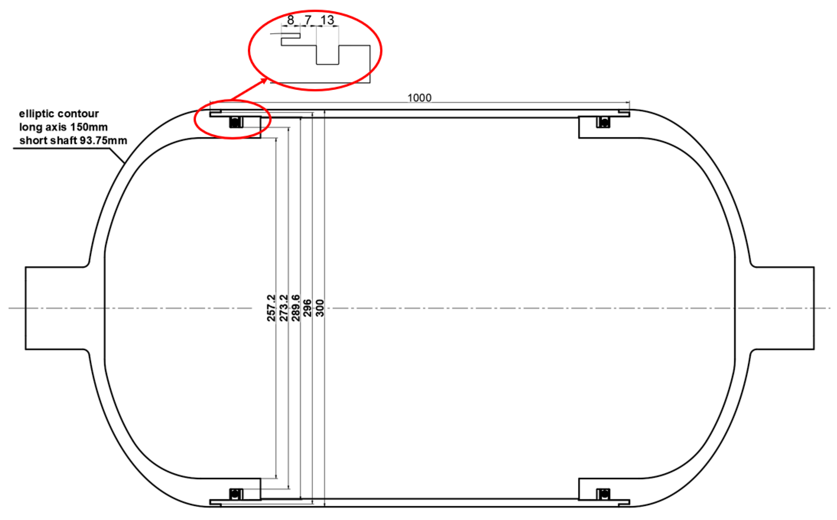
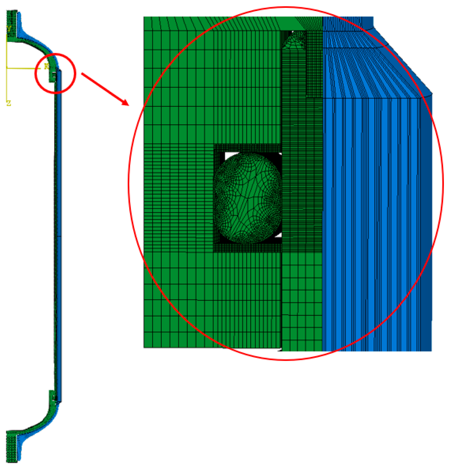
Hydrogen storage cylinders made of composite materials were simulated and analyzed, focusing on the forces and deformation of the O-rings in their sealing structure. The simulation was modeled according to the real size, and the liner is shown in Figure 5. In order to simplify the computational model, the hydrogen storage cylinder was a 1/36 model, as shown in Figure 6, which includes a metal liner, sealing elements (O-rings and two flat gaskets), and a fiber winding layer. A cylindrical coordinate system was established, the boundary condition was circular symmetry, and the pole hole of one end head was fixed. The mesh type was a three-dimensional cubic linear reduced integral cell (C3D8R). Because the material was nonlinear, the structure was nonhomogeneous and discontinuous, and the deformation, stress, and contact state were complex. The simulated procedure type was Dynamic, Explicit. In the model, hard contact was used between the head, cylinder and sealing element.
Figure 5.
Schematic diagram of the parameters of the size of the liner.

Figure 6.
Model of a hydrogen storage cylinder.
In order to accurately simulate the behavior of the sealing elements during the process of assembly of the hydrogen storage cylinder and the process of internal pressure loading, the finite element loading analysis step is divided into four steps. Step 1: The pre-installation process of the inner was simulated. In the simulation, the barrel was fixed, and axial displacements toward the cylinder were applied to the left and right heads to make the heads and the barrel a single unit and establish the initial seal assembly state. Step 2: The metal liner was bound to the fiber layer [21], and the head end was restrained for axial displacement; then, a self-tightening pressure of 55 MPa was applied to the interior of the hydrogen storage cylinder. Step 3: Pressure relief. Step 4: A working pressure of 35 MPa was applied to the interior of the hydrogen storage cylinder.
In the simulation, the model involves a variety of materials. The inner liner is aluminum alloy, and the true stress–true strain principal relationship is used. Its plasticity parameters are shown in Table 1. E = 70 GPa, u = 0.3. The O-ring is made of rubber. To simulate the geometric nonlinear behavior under large deformation accurately, this paper adopts the two-parameter Mooney–Rivlin model to describe its intrinsic relationship, and its simplified model is shown in Equation:
where W is the strain potential energy; I1 and I2 are the first and second strain bias invariants; J is the volume ratio; C10 and C01 are the material coefficients; and D1 is the material incompressibility coefficient. C10 = 1.25 MPa, C01 = 5.1 MPa, and D1 = 0.003.
W = C10(I1 − 3) + C01(I2 − 3) + (J − 1)2/D1

Table 1.
True stress–true strain intrinsic parameters used for the metal inner liner.
The fiber winding layer material is a carbon fiber material, the material properties of the carbon fibers are defined using a user subroutine, and the failure criterion uses the three-dimensional Chang–Chang damage initiation criterion [22,23], which takes into account the possible fiber stretching, fiber compression, matrix stretching, and matrix compression of the fibers. The material property parameters of carbon fibers are shown in Table 2.
Table 2.
Parameters of carbon fiber material properties.
3. Results and Discussion
3.1. Accuracy of Finite Element Methods
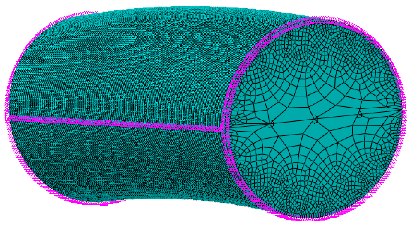
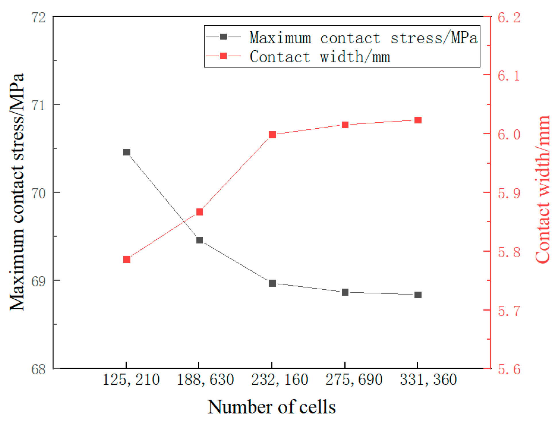
The O-ring cells were refined to minimize calculation errors caused by differences in the number of cells and to ensure the accuracy and efficiency of the calculations, as shown in Figure 7. Maximum contact stress and contact width of the O-ring were used as evaluation indexes. As shown in Figure 8, when the number of O-ring cells reached 275,690, the results of the maximum contact stress and contact width tended to be stable, and the resulting error was less than 1%, so the number of O-ring cells was selected to be 275,690.
Figure 7.
O-ring meshing.
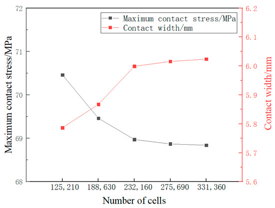
Figure 8.
Maximum contact stress and contact width results.
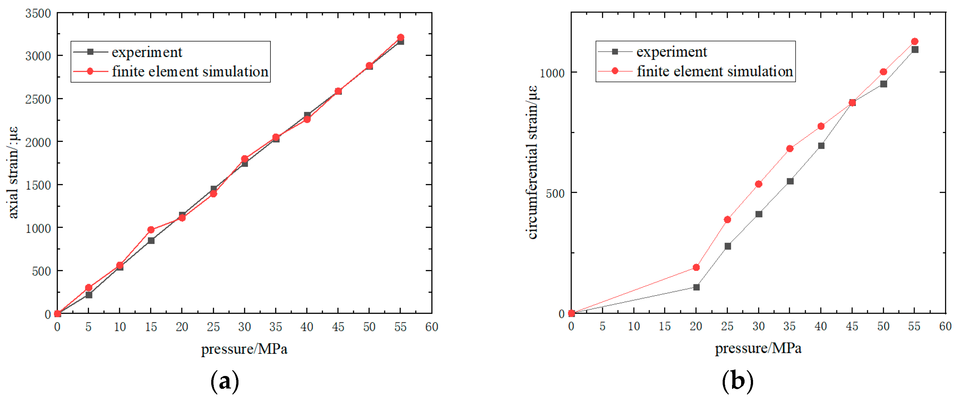
This paper focuses on the reliability of the sealing structure. Composite fibers provide axial and circumferential strength to the liner, and fiber strength affects the sealing effect of the split liner, so the strain gauge data of the fiber at the junction of the head and cylinder were selected for comparison with the finite element simulation. In the experiment, the strain gauge recorded the change in strain value with time, and the digital pressure gauge recorded the change in pressure with time. Finally, the change of strain value with pressure was obtained through data processing. As shown in Figure 9a, the experimental results of axial strain are consistent with those of the finite element method. As shown in Figure 9b, the trend of the experimental and simulated results of the circumferential strain is relatively close. They verify the accuracy of the fiber parameters in the model and the grid of the gas cylinder model.
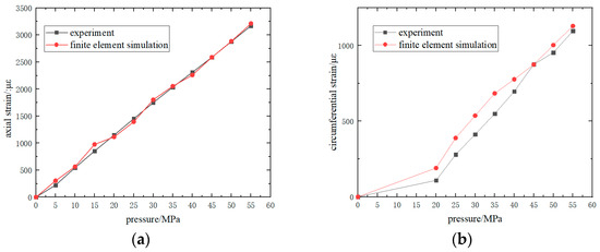
Figure 9.
Experimental and simulated fiber strain result curves: (a) axial strain; (b) cyclic strain.
3.2. Influence Analysis of Gas Cylinder Sealing Structure Parameters
To analyze the sealing performance of the O-ring [24], two evaluation indexes were used: contact stress and contact width. The condition that the O-ring can achieve sealing is that when the O-ring is squeezed, the maximum contact stress on the contact surface is greater than the medium pressure, and there is sufficient contact width, that is, the arc length of the part where the stress on the O-ring contact surface is greater than the medium pressure. In this paper, the contact stress and contact width on the main contact surface, that is, the contact surface between the O-ring and the cylinder, were used to determine the seal reliability. The influences of the O-ring compression rate ε, the distance l from the straight edge section of the head to the sealing groove, and the thickness d of the head on the sealing performance of the gas cylinder were explored, as shown in Figure 10.
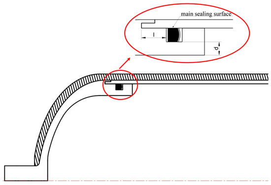
Figure 10.
Geometric parameters of the seal structure.
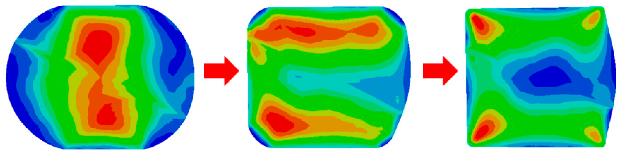
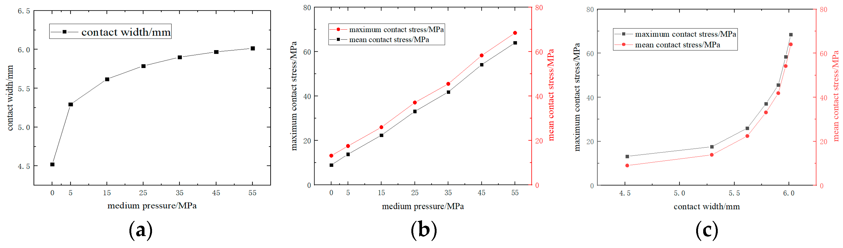
The O-ring can be divided into two stages of sliding seal and extrusion seal in the process of bearing the internal pressure of the medium, as shown in Figure 11. When the pressure is low, the O-ring slides to the side without the internal pressure of the medium, and the contact width of the O-ring increases with the increase in the internal pressure of the medium, and the growth rate is faster. When the medium pressure reaches a certain level, the O-ring cannot slide, and one side of the O-ring is tightly attached to the sealing groove wall. With the increase in the internal pressure of the medium, the O-ring is squeezed and deformed to complete the seal. At this time, the contact width of the O-ring increases with the increase in the internal pressure of the medium, but the growth rate is slow, as shown in Figure 12a. When the O-ring is subjected to the internal pressure of the medium, whether it is a sliding seal or an extrusion seal, the contact stress increases approximately linearly with the internal pressure of the medium, as shown in Figure 12b. In general, the contact stress does not increase linearly with the contact width, and the growth rate shows a trend of first busy and then fast, as shown in Figure 12c.
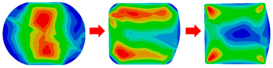
Figure 11.
Deformation process of O-ring under pressure.
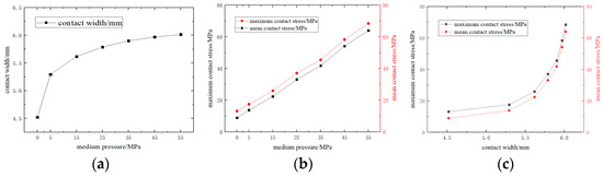
Figure 12.
Analysis of O-ring under pressure: (a) relationship between contact width and pressure; (b) relationship between contact stress and pressure; and (c) relationship between contact stress and contact width.
3.2.1. Sealing of O-Rings at Different Compression Rates
The compression rate of the O-ring should generally be between 15% and 25%. It is important to select the appropriate compression rate based on specific conditions to ensure the equipment’s normal use and service life. Under fixed conditions of a sealing groove height of 8.2 mm, we selected rubber O-rings with compression rates of 16%, 18%, 20%, and 22% to simulate and calculate their performance under a 55 MPa self-tightening pressure condition and a 35 MPa working pressure condition after self-tightening pressure.
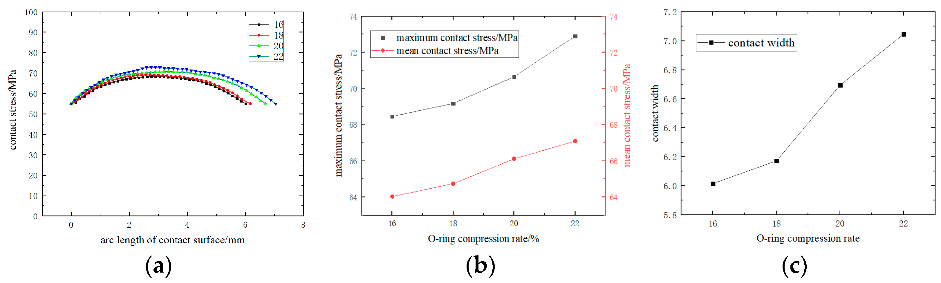
The contact stress and contact width on the O-ring were extracted from the main sealing surface, and the contact stress distribution and contact width size were analyzed from the part of the contact surface where the contact stress was greater than the medium pressure. As shown in Figure 13a and Figure 14a, under the self-tightening pressure condition and the working pressure condition after self-tightening, the contact stress on the contact surface of the O-ring was greater than the medium pressure, and the width of the sealing surface was more than 50% of the O-ring wire diameter so that it could form a good sealing condition. Under self-tightening pressure conditions, the O-ring’s contact stress increased with the compression ratio. This increase showed a slow-fast trend, as Figure 13b depicts. Similarly, the contact width increased with the compression rate increase, showing a slow-fast-slow trend, as shown in Figure 13c. Under working pressure conditions after self-tightening, the trends of contact stress and contact width with compression rate were consistent with those under self-tightening pressure conditions, as shown in Figure 14b,c. Under the same internal pressure, increasing the O-ring compression rate also increased the deformation amount, resulting in a closer fit between the O-ring surface and the seal construct, thereby improving the sealing effect. Increasing the O-ring compression rate can improve its effectiveness. However, a compression rate that is too high can lead to high Mises stress on the O-ring, resulting in stress relaxation and plastic deformation over time. This can cause a loss of elasticity, leading to leakage and sealing failure, ultimately shortening the O-ring’s service life [25,26,27].
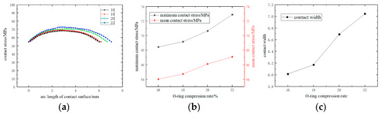
Figure 13.
Sealing of O-rings at different compression rates under a 55 MPa self-tightening pressure condition: (a) division of contact stress under different parameters; (b) the trend of contact stress under different parameters; and (c) the trend of contact width under different parameters.
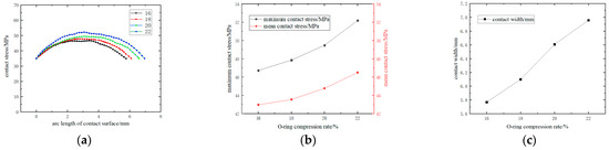
Figure 14.
Sealing of O-rings at different compression rates under a 35 MPa working pressure condition after self-tightening pressure: (a) Division of contact stress under different parameters; (b) The trend of contact stress under different parameters; (c) The trend of contact width under different parameters.
3.2.2. Sealing of Different Distances from the Straight Edge Section to the Sealing Groove of the Head
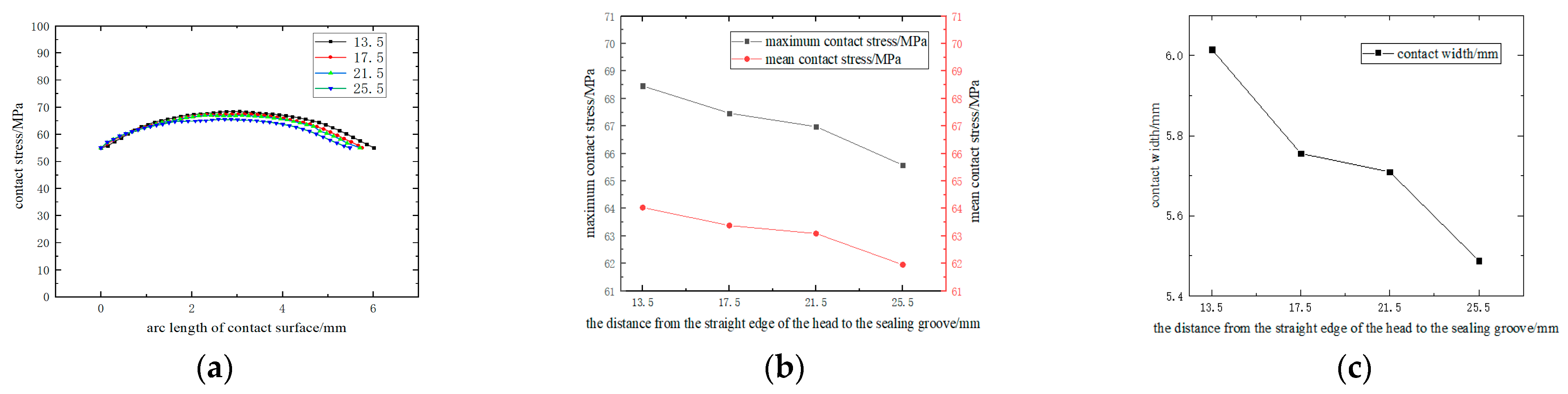
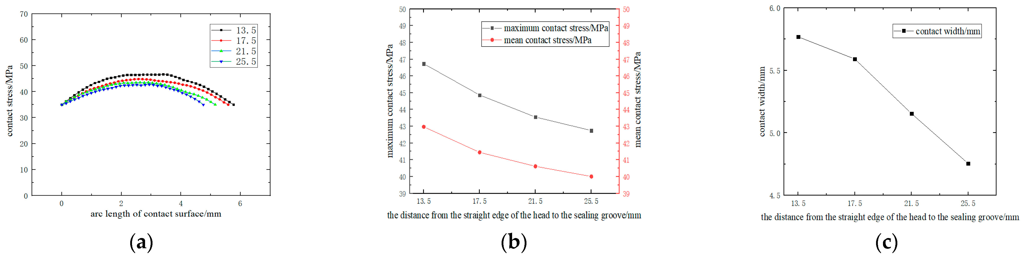
The sealing performance of the cylinder is affected by the distance from the straight edge section to the sealing groove of the head. Therefore, we selected the distance from the straight edge section of the head to the sealing groove as 13.5 mm, 17.5 mm, 21.5 mm, and 25 mm to simulate and calculate their performance under a 55 MPa self-tightening pressure condition and a 35 MPa working pressure condition after self-tightening pressure. The distribution of contact stresses on the O-ring contacting surfaces is shown in Figure 15a and Figure 16a. Under the self-tightening pressure condition and the working pressure condition after self-tightening, the contact stress on the contact surface of the O-ring was greater than the medium pressure, and the width of the sealing surface was more than 45% of the O-ring wire diameter so that it could form a good sealing condition. Under self-tightening pressure conditions, the contact stress of the O-ring decreased with the increase in the distance from the straight edge section of the head to the sealing groove, as depicted in Figure 15b. Similarly, the contact width decreased with the increase in the distance from the straight edge section of the head to the sealing groove, as depicted in Figure 15c. Under working pressure conditions after self-tightening, contact stress and contact width also decreased with the increase in the distance from the straight edge section of the head to the sealing groove, as shown in Figure 16b,c.
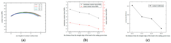
Figure 15.
Sealing of different distances from the straight edge section to the sealing groove of the head under a 55 MPa self-tightening pressure condition: (a) division of contact stress under different parameters; (b) the trend of contact stress under different parameters; and (c) the trend of contact width under different parameters.
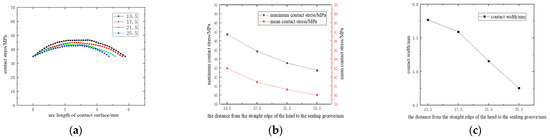
Figure 16.
Sealing of different distances from the straight edge section to the sealing groove of the head under a 35 MPa working pressure condition after self-tightening pressure: (a) division of contact stress under different parameters; (b) the trend of contact stress under different parameters; and (c) the trend of contact width under different parameters.
The contact reason that the stress and contact width decrease with the increase in the distance from the straight edge section of the head to the sealing groove is that, under internal pressure, the head is more rigid than the cylinder and can be considered a rigid body relative to the cylinder. The cylinder will deform under the internal pressure, slightly arching from the middle to the sides, enlarging the gap between the cylinder and the sealing structure. At this point, the further away the sealing structure is from the straight edge portion of the head, the more significant the gap will be, resulting in a worse sealing effect. Hence, the sealing effect decreases as the distance from the straight edge section of the head to the sealing groove increases. However, it is essential to ensure that the distance from the straight edge of the head to the sealing groove is not too short, as this can result in unreliable sealing performance. The head and barrel are independent, and the composite fibers provide the axial force to hold them together. Suppose that the outer layer of fibers cannot provide sufficient axial pressure at high internal pressures due to material properties or the winding process. In that case, the cylinder and head may experience relative displacement. The cylinder will eventually disengage from the head, resulting in the inability to form a sealing surface with the O-ring. This will negatively impact the sealing performance.
3.2.3. Sealing of Different Head Thicknesses
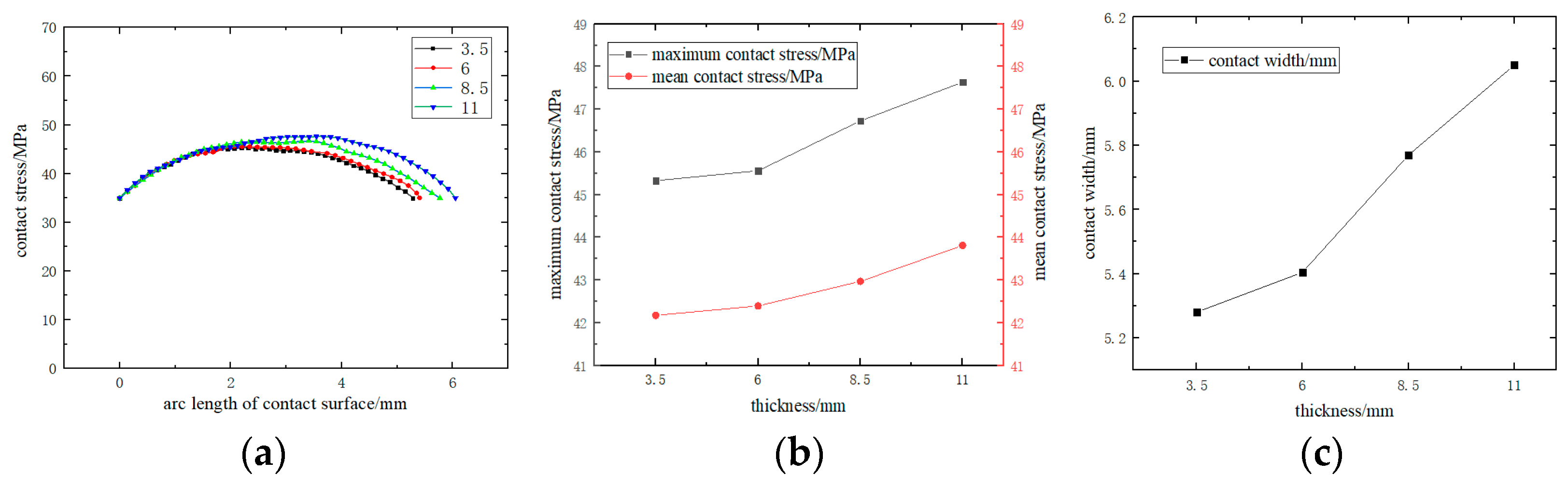
The sealing performance of the cylinder is affected by the head thickness. Therefore, we chose head thicknesses of 3.5 mm, 6 mm, 8.5 mm, and 11 mm to simulate and calculate their performance under a 55 MPa self-tightening pressure condition and a 35 MPa working pressure condition after self-tightening pressure. The distribution of contact stresses on the O-ring contacting surfaces is shown in Figure 17a and Figure 18a. Under the self-tightening pressure condition and the working pressure condition after self-tightening, the contact stress on the contact surface of the O-ring was greater than the medium pressure, and the width of the sealing surface was more than 50% of the O-ring wire diameter so that it could form a good sealing condition. Under self-tightening pressure conditions, the contact stress of the O-ring increased with the increase in head thickness, as depicted in Figure 17b. Similarly, the contact width increased with head thickness, as shown in Figure 17c. Under working pressure conditions after self-tightening, contact stress and contact width increased with head thickness, as shown in Figure 18b,c. As shown in Figure 19, the head was subject to an internal pressure load of P1, P2, and P3, all equal in size. The O-ring was deformed under this pressure load and simultaneously exerted a downward force P4 on the head, completing the sealing process. To ensure effective sealing, the contact stress of the O-ring was greater than the internal pressure of the medium, so the downward force P4 given by the O-ring to the head was greater than the internal pressure load, and the sealing groove end of the head was deformed downward. Therefore, the greater the head thickness is, the smaller the downward deformation of the head sealing groove under pressure load is, the smaller the gap distance between the cylinder and sealing structure is, and the better the sealing performance is.
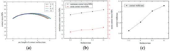
Figure 17.
Sealing of different head thicknesses under a 55 MPa self-tightening pressure condition: (a) division of contact stress under different parameters; (b) the trend of contact stress under different parameters; and (c) the trend of contact width under different parameters.
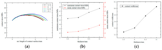
Figure 18.
Sealing of different head thicknesses under a 35 MPa working pressure condition after self-tightening pressure: (a) division of contact stress under different parameters; (b) the trend of contact stress under different parameters; and (c) the trend of contact width under different parameters.
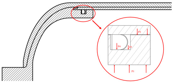
Figure 19.
Head force analysis.
4. Conclusions
To address the limitations of the integral hydrogen storage cylinder liner, a split hydrogen storage cylinder liner was designed and tested for its sealing feasibility through experiments. Additionally, the influence of cylinder structural parameters on sealing performance was studied using finite element simulation and analysis methods. The conclusions are presented below:
(1) The finite element simulation and analysis method involves establishing an internal pressure model for a composite gas cylinder with multiple materials and complex contacts. The pre-installation process of the O-ring can be accurately simulated by applying a certain axial displacement to the left and right heads. The calculation results are consistent with the actual situation. The internal pressure loading sequence is 0~55~0~35 MPa, which simulates the O-ring sealing performance under the self-tightening pressure condition and the working pressure condition after self-tightening. It provides a reference for the design of the cylinder seal.
(2) In this paper, the effects of the O-ring compression rate, the distance from the straight edge section of the head to the sealing groove, and the thickness of the head on the sealing performance of gas cylinders are investigated using finite element simulation and analysis. The results indicate that increasing the compression rate of the sealing element improves the sealing performance. However, an excessive compression rate will lead to a greater compression deformation of the O-ring when subjected to large medium internal pressure, resulting in stress concentration and Von Mises stress increase, which may lead to stress relaxation and the plastic strain of the sealing element under long service time, shortening its service life. Reducing the distance between the straight edge of the head and the sealing groove will also improve the sealing performance. However, if the distance is too short, the head and the cylinder will slide relative to each other when subjected to high internal pressure, and the cylinder and the sealing element will not produce the sealing surface, resulting in seal failure. Increasing the thickness of the cylinder head can improve its sealing performance. The greater the thickness of the head, the smaller the downward deformation of the pressure of the sealing groove of the head, the smaller the change in the gap between the cylinder and the sealing structure, and the more effectively the O-ring can be compressed to produce greater deformation, improving the contact stress and contact width of the O-ring; therefore, increasing the thickness of the head can improve the sealing performance. However, if the head is too thick, it will cause the overall weight of the cylinder to be larger, reducing the economy of gas storage and transportation. The sealing performance of a hydrogen storage cylinder is influenced by multiple factors, including the compression rate of the O-ring, the distance from the straight edge of the head to the sealing groove, and the thickness of the head. This paper only explores the influence of a single factor on the sealing performance of hydrogen storage cylinders and the sealing mechanism. In future research, we will obtain the optimal structure parameters through a large number of simulations and mathematical algorithms.
Author Contributions
Conceptualization, G.T. and X.Z.; methodology, G.T.; software, G.T. and Y.L.; validation, Y.L. and F.L.; writing—original draft preparation, G.T.; writing—review and editing, X.Z.; supervision, X.Z. and X.L. All authors have read and agreed to the published version of the manuscript.
Funding
This research was funded by National Major Scientific Research Instrument Development Program of China (No. 12027901).
Data Availability Statement
Data are contained within the article.
Conflicts of Interest
The authors declare no conflicts of interest.
References
- Aziz, G.; Sarwar, S.; Waheed, R.; Khan, M.S. Significance of Hydrogen Energy to Control the Environmental Gasses in Light of COP26: A Case of European Countries. Resour. Policy 2023, 80, 103240. [Google Scholar] [CrossRef]
- Lin, Y.; He, L.; Chen, T.; Zhou, D.; Wu, L.; Hou, X.; Zheng, C. Cost-Effective and Environmentally Friendly Synthesis of 3D Ni2P from Scrap Nickel for Highly Efficient Hydrogen Evolution in Both Acidic and Alkaline Media. J. Mater. Chem. A 2018, 6, 4088–4094. [Google Scholar] [CrossRef]
- Abdalla, A.M.; Hossain, S.; Nisfindy, O.B.; Azad, A.T.; Dawood, M.; Azad, A.K. Hydrogen Production, Storage, Transportation and Key Challenges with Applications: A Review. Energy Convers. Manag. 2018, 165, 602–627. [Google Scholar] [CrossRef]
- Muljadi, E.; Hossain, S. Powering Transportation with Hydrogen Fuel Cells [About This Issue]. IEEE Electrif. Mag. 2018, 6, 2–3. [Google Scholar] [CrossRef]
- Barthelemy, H.; Weber, M.; Barbier, F. Hydrogen Storage: Recent Improvements and Industrial Perspectives. Int. J. Hydrogen Energy 2017, 42, 7254–7262. [Google Scholar] [CrossRef]
- Moradi, R.; Groth, K.M. Hydrogen Storage and Delivery: Review of the State of the Art Technologies and Risk and Reliability Analysis. Int. J. Hydrogen Energy 2019, 44, 12254–12269. [Google Scholar] [CrossRef]
- Xia, Q.X.; Xie, S.W.; Huo, Y.L.; Ruan, F. Numerical Simulation and Experimental Research on the Multi-Pass Neck-Spinning of Non-Axisymmetric Offset Tube. J. Mater. Process. Technol. 2008, 206, 500–508. [Google Scholar] [CrossRef]
- Huang, C.-C.; Hung, J.-C.; Hung, C.; Lin, C.-R. Finite Element Analysis on Neck-Spinning Process of Tube at Elevated Temperature. Int. J. Adv. Manuf. Technol. 2011, 56, 1039–1048. [Google Scholar] [CrossRef]
- Pramod, R.; Krishnadasan, C.K.; Siva Shanmugam, N. Design and Finite Element Analysis of Metal-Elastomer Lined Composite over Wrapped Spherical Pressure Vessel. Compos. Struct. 2019, 224, 111028. [Google Scholar] [CrossRef]
- Zhou, C.; Zheng, J.; Gu, C.; Zhao, Y.; Liu, P. Sealing Performance Analysis of Rubber O-Ring in High-Pressure Gaseous Hydrogen Based on Finite Element Method. Int. J. Hydrogen Energy 2017, 42, 11996–12004. [Google Scholar] [CrossRef]
- Barboza Neto, E.S.; Chludzinski, M.; Roese, P.B.; Fonseca, J.S.O.; Amico, S.C.; Ferreira, C.A. Experimental and Numerical Analysis of a LLDPE/HDPE Liner for a Composite Pressure Vessel. Polym. Test. 2011, 30, 693–700. [Google Scholar] [CrossRef]
- Cho, S.-M.; Kim, K.-S.; Lee, S.-K.; Jung, G.-S.; Lee, S.-K.; Lyu, S.-K. Effect of Dome Curvature on Failure Mode of Type4 Composite Pressure Vessel. Int. J. Precis. Eng. Manuf. 2018, 19, 405–410. [Google Scholar] [CrossRef]
- Park, G.; Jang, H.; Kim, C. Design of Composite Layer and Liner for Structure Safety of Hydrogen Pressure Vessel (Type 4). J. Mech. Sci. Technol. 2021, 35, 3507–3517. [Google Scholar] [CrossRef]
- Zhu, J.; Li, Y.; Cao, W.; Li, Y.; Gao, Z. Failure Analysis of Novel BOSS Structures for Type IV Hydrogen Storage Vessels. Energies 2023, 16, 4005. [Google Scholar] [CrossRef]
- Zheng, Y.; Tan, Y.; Zhou, C.; Chen, G.; Li, J.; Liu, Y.; Liao, B.; Zhang, G. A Review on Effect of Hydrogen on Rubber Seals Used in the High-Pressure Hydrogen Infrastructure. Int. J. Hydrogen Energy 2020, 45, 23721–23738. [Google Scholar] [CrossRef]
- Zhou, C.; Chen, G.; Xiao, S.; Hua, Z.; Gu, C. Study on Fretting Behavior of Rubber O-Ring Seal in High-Pressure Gaseous Hydrogen. Int. J. Hydrogen Energy 2019, 44, 22569–22575. [Google Scholar] [CrossRef]
- Zhang, H.; Sun, Y.; Li, C.; Wang, H. Optimal Design of the Sealing Structure of a Hydraulic Cylinder on the Basis of a Surrogate Model. Adv. Mater. Sci. Eng. 2020, 2020, 1753964. [Google Scholar] [CrossRef]
- Li, Z. Study on the Sealing Performance of O-Ring under High-Pressure Environment. J. Phys. Conf. Ser. 2023, 2419, 012005. [Google Scholar] [CrossRef]
- Wu, E.; Zhao, Y.; Zhao, B.; Xu, W. Fatigue Life Prediction and Verification of High-Pressure Hydrogen Storage Vessel. Int. J. Hydrogen Energy 2021, 46, 30412–30422. [Google Scholar] [CrossRef]
- Son, D.-S.; Hong, J.-H.; Chang, S.-H. Determination of the Autofrettage Pressure and Estimation of Material Failures of a Type III Hydrogen Pressure Vessel by Using Finite Element Analysis. Int. J. Hydrogen Energy 2012, 37, 12771–12781. [Google Scholar] [CrossRef]
- Zu, L.; Xu, H.; Wang, H.; Zhang, B.; Zi, B. Design and Analysis of Filament-Wound Composite Pressure Vessels Based on Non-Geodesic Winding. Compos. Struct. 2019, 207, 41–52. [Google Scholar] [CrossRef]
- Hou, J.P.; Petrinic, N.; Ruiz, C.; Hallett, S.R. Prediction of Impact Damage in Composite Plates. Compos. Sci. Technol. 2000, 60, 273–281. [Google Scholar] [CrossRef]
- Hou, J.P.; Petrinic, N.; Ruiz, C. A Delamination Criterion for Laminated Composites under Low-Velocity Impact. Compos. Sci. Technol. 2001, 61, 2069–2074. [Google Scholar] [CrossRef]
- Liu, D.; Yun, F.; Jiao, K.; Wang, L.; Yan, Z.; Jia, P.; Wang, X.; Liu, W.; Hao, X.; Xu, X. Structural Analysis and Experimental Study on the Spherical Seal of a Subsea Connector Based on a Non-Standard O-Ring Seal. J. Mar. Sci. Eng. 2022, 10, 404. [Google Scholar] [CrossRef]
- Zhao, Y.; Feng, Z.; Li, Y.; Feng, L.; Li, Q.; Cui, W. Analysis of Contact Surface Wear Performance of O-Ring Dynamic Seal Based on Archard Model. Teh. Vjesn. 2022, 29, 281654. [Google Scholar] [CrossRef]
- He, S.; Peng, Y.; Qiu, S.; Du, X.; Jin, Y. Sealing Performance of Sealing Structure in a Sediment Sampler under Ultra-High Pressure. Sci. Rep. 2023, 13, 18548. [Google Scholar] [CrossRef]
- Windslow, R.J.; Busfield, J.J.C. Viscoelastic Modeling of Extrusion Damage in Elastomer Seals. Soft Mater. 2019, 17, 228–240. [Google Scholar] [CrossRef]


Disclaimer/Publisher’s Note: The statements, opinions and data contained in all publications are solely those of the individual author(s) and contributor(s) and not of MDPI and/or the editor(s). MDPI and/or the editor(s) disclaim responsibility for any injury to people or property resulting from any ideas, methods, instructions or products referred to in the content. |
© 2024 by the authors. Licensee MDPI, Basel, Switzerland. This article is an open access article distributed under the terms and conditions of the Creative Commons Attribution (CC BY) license (https://creativecommons.org/licenses/by/4.0/).