Article

Study of the Transient Heat Transfer of a Single-U-Tube Ground Heat Exchanger by Integrating a Forward-Difference Numerical Scheme with an Analytical Technique

1
Purdue Polytechnic Institute, Purdue University, West Lafayette, IN 47907, USA
2
Department of Mechanical Engineering, Jigjiga University, Jigjiga P.O. Box 1020, Ethiopia
3
Department of Mechanical Engineering, King Abdulaziz University, P.O. Box 80204, Jeddah 21589, Saudi Arabia
4
Department of Mechanical, Industrial and Mechatronics Engineering, Toronto Metropolitan University, Toronto, ON M5B 2K3, Canada
*
Author to whom correspondence should be addressed.
Processes 2024, 12(12), 2867; https://doi.org/10.3390/pr12122867
Submission received: 17 November 2024 / Revised: 9 December 2024 / Accepted: 10 December 2024 / Published: 14 December 2024
(This article belongs to the Special Issue Heat and Mass Transfer Phenomena in Energy Systems)

Abstract

:
This study presents the development of a novel computational technique for modeling the transient heat transfer in the outer and inner regions of a single U-tube ground heat exchanger. The modeling approach couples a forward-difference numerical technique with a well-established analytical method with the aim of reducing the two-dimensional axisymmetric heat transfer problem into a one-dimensional problem, which has the benefit of reducing the computational time. Furthermore, the suggested method is numerically stable compared to a full numerical scheme, and the solution converges for a time step of up to 150 min. This is because the suggested method computes the heat transfer of the streaming fluid in the U-tube, which has a lower thermal capacitance, using the analytical technique, resulting in numerical stability at a larger time step, while the full numerical scheme has stability issues at a large time step as it computes the heat transfer of the flowing fluid in the U-tube, which also requires more computational time than the suggested method. In this model, numerical and analytical analyses are coupled with borehole wall temperature. The time-varying temperature histories of the grout material inside the borehole, the borehole wall, and the surrounding soil are presented. In addition, the time variations in the exit fluid temperature and the energy storage within the grout and the outer soil material are presented. The results show that the energy storage in the grout material reaches 62 MJ at the end of 1000 h of ground heat exchanger charging operation, while the energy storage in the surrounding soil can be as high as 7366 MJ. This study also investigates the effect of mass flow rate on the heat transfer performance of the ground heat exchanger.

1. Introduction

Energy is one of the essential and fundamental constituents for sustaining humanity [1,2,3,4,5,6,7]. However, the use of fossil fuels has an adverse impact on the environment and needs to be substituted with that of renewable energy [8,9,10,11,12,13,14]. As a result, transitioning to greener energies is vital. The world is giving more attention to renewable energy technologies [15,16,17,18,19,20]. It is expected that the market for green energy will rise significantly in the near future [21,22,23]. Nevertheless, renewable energy sources do not supply power consistently at all times of the day, instead following a pattern of intermittency, and energy storage is one way of overcoming this problem and ensuring the reliability of renewable energy systems [24,25,26]. Thermal energy storage is the most efficient way to solve the problem of intermittent power fluctuations in renewable energy sources [27,28], and it has wide applications, especially within solar energy systems [29]. It is also an important way of storing energy with the objective of balancing supply and demand [30], especially for heating and cooling applications. As stated by the International Energy Agency (IEA), the worldwide demand for heat energy is more than 50% of our total energy consumption. Buildings utilize more than 30% of all of the energy consumed worldwide [31,32,33,34,35]. Ground heat exchangers, especially borehole heat exchangers, are energy storage systems that play a significant role in building applications; specifically, they can be utilized by integrating them with ground source heat pumps [36]. The enormous heat capacitance and steady thermal features underground result in the higher performance characteristics of ground-source heat pumps [37,38,39]. As a result, ground-source heat pumps offer dependable solutions for meeting the necessary cooling and heating demand for buildings [40].
Modeling ground heat exchangers is an essential factor in designing and optimizing ground heat exchangers [41]. Various modeling techniques have been suggested by researchers in the field. Ahmadfard and Bernie [42] suggested two methods for the thermal characteristics of a ground heat exchanger. The first method utilizes the concept of heat transfer and storage efficiencies in relation to the state-of-charge of the ground heat exchanger, while the second approach implements a thermal response factor based on a thermal resistance network. Hosseinnia et al. [43] numerically studied a ground heat exchanger with a constant load by computing a Navier–Stokes equation for the streaming fluid in the U-tube and heat balance equations for the ground using ANSYS commercial software. Lui et al. [44] studied the flow and heat transfer features of a coaxial ground heat exchanger by utilizing a numerical approach. The effect of the geometric parameters of the heat exchanger, such as pitch ratio, thickness ratio, and width ratio, on the ground heat exchanger’s performance was studied. Guo et al. [45,46] proposed a semi-analytical method which was capable of capturing the varying heat flux along the depth of a ground heat exchanger. Shen et al. [47] suggested a novel analytical model which depends on the finite line source technique, with the objective of investigating the heat transfer of deep borehole ground heat exchangers. Chen et al. [48] studied a deep ground heat exchanger by utilizing a response factor matrix technique, which was based on a well-designed data structure and a simple analytical method, and also implemented a superposition algorithm. In their analysis, they investigated the ground heat exchanger’s heat capacity and thermal radius. Extremera-Jiménez et al. [49] implemented both a finite line source technique and a thermal response test to analyze the transient heat transfer of a ground heat exchanger with the objective of exploiting a computational technique with a low computing time, in comparison to numerical and artificial intelligence techniques, which involve long computing times. Li et al. [50] developed a novel algorithm which is capable of estimating the performance parameters of a ground heat exchanger. The algorithm combines three key elements, which are the zero-order Tikhonov regularization strategy, a derivative-enhanced objective function, and a short-time model. Kerme and Fung [51,52] undertook a performance analysis and a heat transfer study of double- and single-U-tube ground heat exchangers. They implemented a full numerical model based on the Crank–Nicolson numerical scheme to investigate the transient heat transfer characteristics of the inside and outside regions of the borehole. Salilih et al. [53] employed the same full numerical scheme based on the Crank–Nicolson numerical technique to study the transient heat transfer of a ground heat exchanger where PCM was considered the backfill material. Salilih et al. [54] suggested a similar computational technique to that in this study which combined the well-known analytical model with the Crank–Nicolson numerical technique to investigate the heat transfer process of a double-U-tube ground heat exchanger. Nevertheless, the technique simplified and ignored the transient heat transfer feature of the inside region of the borehole. In this study, a forward-difference numerical scheme is integrated with the well-known analytical model to study the transient heat transfer process in a single-U-tube borehole heat exchanger. Unlike the previous study, the suggested model captures the transient heat transfer in both the inside and outside regions of the borehole. The significance of this study lies in significantly reducing the computational time which is encountered when employing the full numerical scheme as the problem is reduced from a two-dimensional axisymmetric problem to a one-dimensional problem. At the same time, the technique helps to understand the transient heat transfer process of both the inner and outer regions of the borehole. Furthermore, the formulated method in this study can replace the simple line-source model, which is a 1D model similar to the model proposed in this study. However, unlike the line-source model, the suggested model considers the details of the complicated geometry of the U-tube with the use of an existing analytical heat transfer model. Unlike the line-source model, it also considers the differences in the thermal properties of the soil and grout. Since the proposed model has low computational time, it can be adopted to model a borehole field or borefield with multiple boreholes similar to those of the line-source model.

2. Mathematical Modeling

Figure 1 shows the actual thermal network of a single-U-tube borehole heat exchanger. However, in this analysis, the thermal network is modified into Figure 2 and Figure 3, in order to comprise the analytical and numerical analyses.
The region of the borehole heat exchanger inside the borehole is considered grout material, while the region of the borehole heat exchanger outside the borehole is considered soil. The boundary between the soil and gout material is the borehole wall. As part of transient heat transfer analysis, an initial temperature of 10.0 °C is considered for the grout, the soil, and the borehole wall.

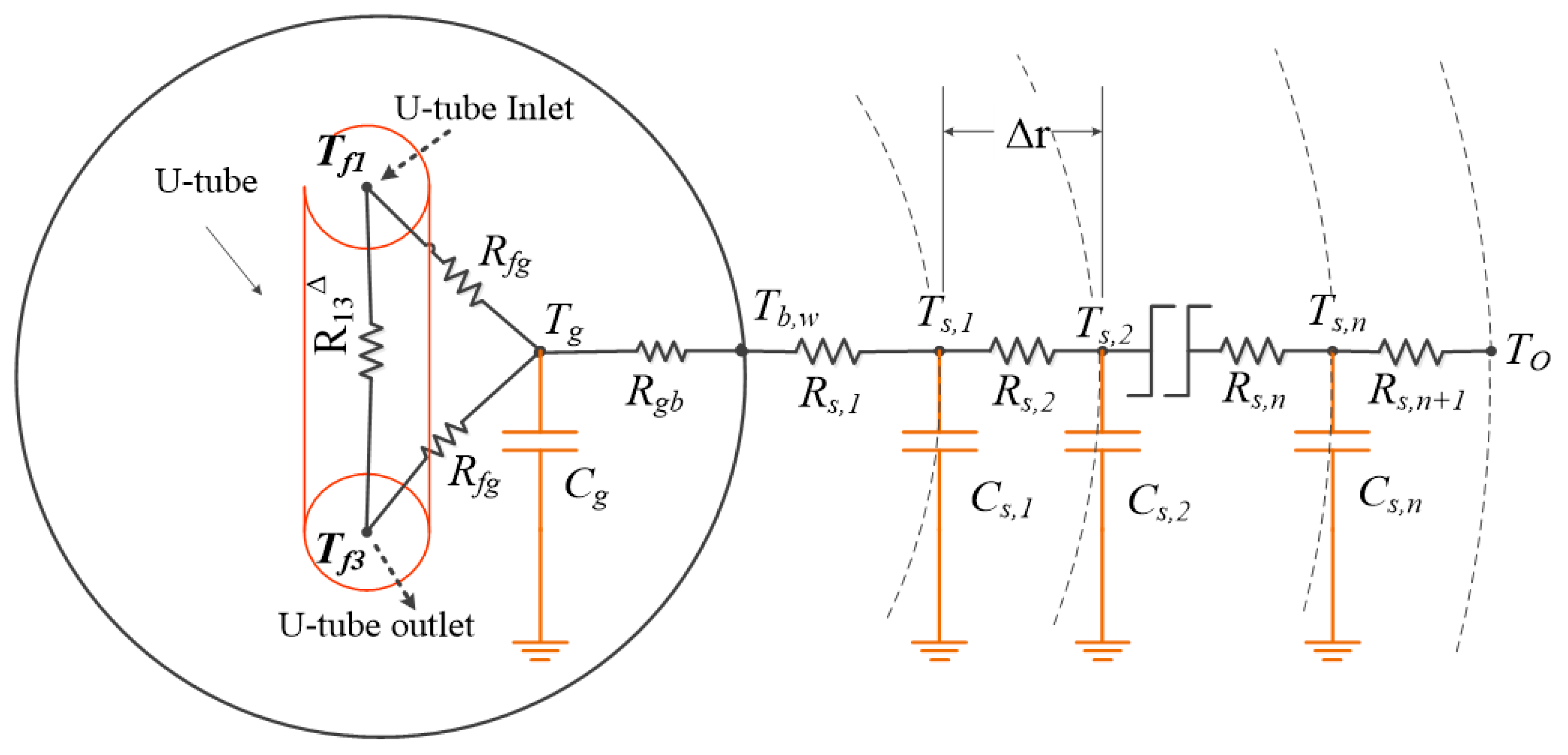
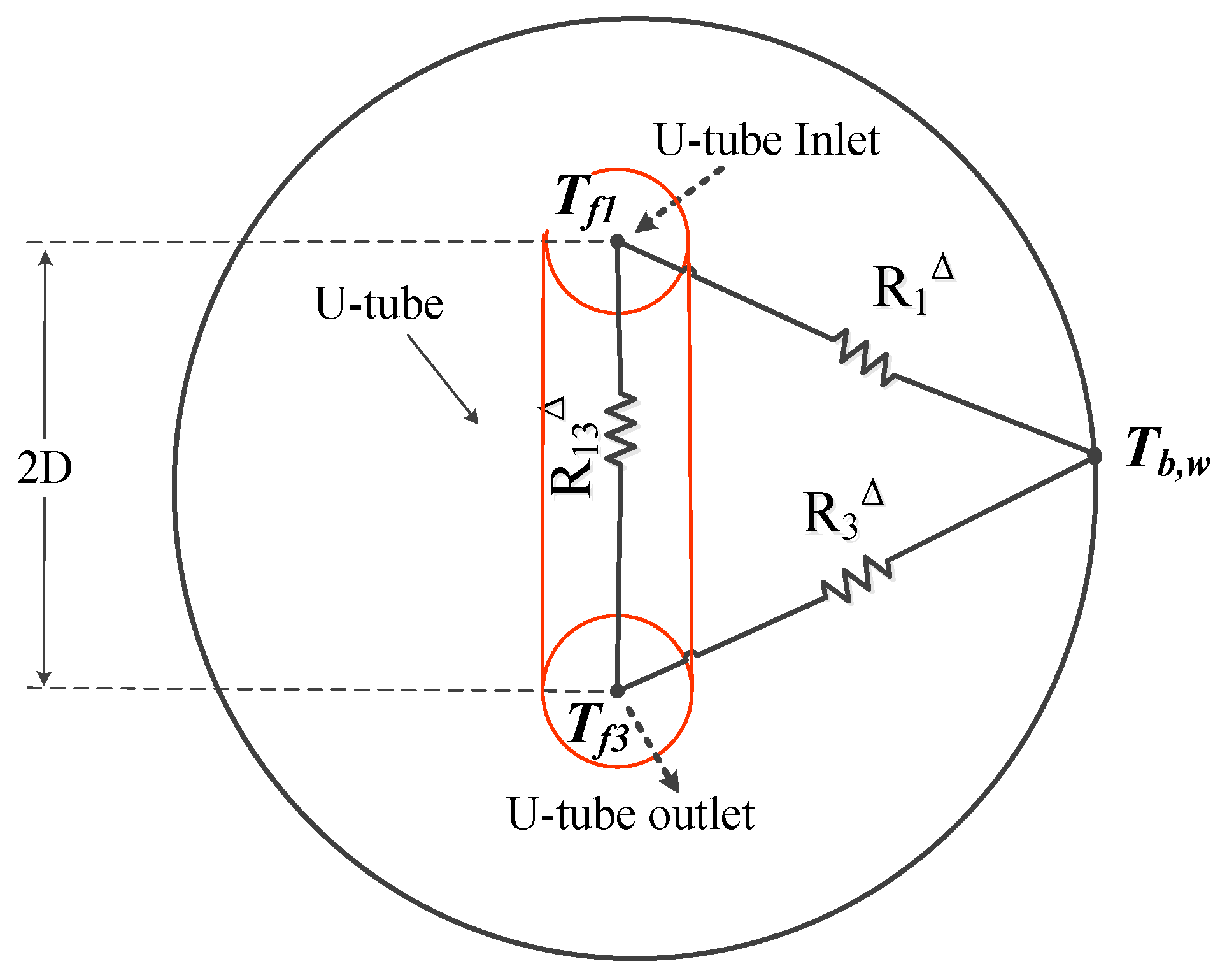
2.1. Analytical Modeling

Figure 2 depicts the thermal network which is implemented for the analysis. The analysis is critical in determining the amount of heat which is exchanged between the streaming fluid in the U-tube and the ground by considering the borehole wall temperature as a reference or input.
The non-dimensional temperature profile of the streaming fluid in the U-tube along the depth of the borehole for the down-running tube ( θ 1 ) and up-running tube ( θ 3 ) are given in Equation (1) [55]:
± d θ 1 d Z = 1 R 1 * + 1 R 13 * θ 1 1 R 13 * θ 3 ± d θ 3 d Z = 1 R 13 * θ 1 + 1 R 1 * + 1 R 13 * θ 3
where R 1 * = m ˙ c p , f H R 11 + R 13 , R 13 * = m ˙ c p , f H R 11 2 R 13 2 R 13   a n d Z = z H .
The non-dimensional temperatures, θ 1 and θ 3 , of Equation (1) are given in Equation (2) [55]:
θ 1 = T f 1 z T b , w T f , i n T b , w θ 3 = T f 3 z T b , w T f , i n T b , w
where T f 1 z is the fluid temperature in the down-running tube at depth z, T f 3 z is the fluid temperature in the up-running tube at depth z, T f , i n is the inlet fluid temperature, and T b , w is the borehole wall temperature. In this study, a 20.0 °C inlet temperature is considered for the streaming fluid in the U-tube.
Equation (1) can be written in a matrix form as presented in Equation (3):
d d Z θ 1 θ 3 = a b b a θ 1 θ 3
where a = 1 R 1 * + 1 R 13 * , b = 1 R 13 * .
Table 1 shows the boundary conditions which are used in the analysis.
R 11 and R 13 of Equation (1) can be expressed using Equation (4) [56,57,58]:
R 11 = 1 2 π k b l n r b r p o k b k s k b + k s l n r b 2 D 2 r b 2 + R p R 13 = 1 2 π k b l n r b 2 D k b k s k b + k s l n r b 2 + D 2 r b 2
The pipe resistance per unit length ( R p ) is the sum of the convective and pipe wall thickness resistances and is expressed with Equation (5) [51,58]:
R p = 1 2 π h i r p i + l n r p o / r p i 2 π k p
The convective coefficient ( h i ) inside the U-tube can be determined with the following equation [51,59]:
h f = 0.023 R e f 0.8 P r f n k f 2 r p i ,
where n = 0.4 for heating while n = 0.3 for cooling.
Equations (1)–(6) can be used to determine the fluid temperature profiles of the down-running and up-running tubes along the depth of the borehole (i.e., T f 1 z and T f 3 z ).
The heat energy transferred from the streaming fluid in the U-tube to the borehole can be given as Equation (7), where the outlet fluid temperature of the U-tube ( T f 3 0 ) can be determined from the computed temperature profile of the U-tube.
Q f = m ˙ c p , f T f , i n T f 3 0

2.2. Numerical Modeling

Figure 3 depicts the one-dimensional thermal network which is considered for the numerical analysis. The numerical analysis is crucial in investigating the temperature history of the grout material inside the borehole and soil material outside the borehole.
The thermal resistance between the grout and the borehole wall for a unit length ( R g b ) can be computed using Equation (8) [60]:
R g b = 1 r ¯ R g
where the center mass ( r ¯ ) can be estimated using Equation (9) [60]:
r ¯ = l n r b 2 2 r p o 2 2 r p o l n r b r p o 2
R g can be estimated using Equation (10) [60]:
R g = R f b R p / 2
where R f b = R 11 + R 13
Considering the grout node, the energy balance of the node can be given as Equation (11):
Q f T g T s , 1 R g b H + R s , 1 = C g d T g d t
Equation (11) can be rewritten as follows:
Q f C g 1 C g R g b H + R s , 1 T g + 1 C g R g b H + R s , 1 T s , 1 = d T g d t
The forward-difference formulation of Equation (12) can be given as follows:
1 Δ t C g R g b H + R s , 1 T g j + Δ t C g R g b H + R s , 1 T s , 1 j + Q f C g Δ t = T g ( j + 1 )
where j is a variable-to-index time step.
The energy balance for the first node of the soil can be given as follows:
T g T s , 1 R g b H + R s , 1 T s , 1 T s , 2 R s , 2 = C s , 1 d T s , 1 d t
Equation (14) can be rewritten as follows:
T g C s , 1 R g b H + R s , 1 1 C s , 1 R g b H + R s , 1 + 1 C s , 1 R s , 2 T s , 1 + T s , 2 C s , 1 R s , 2 = d T s , 1 d t
The forward-difference formulation of Equation (15) can be given as follows:
Δ t C s , 1 R g b H + R s , 1 T g j + 1 Δ t C s , 1 R g b H + R s , 1 + Δ t C s , 1 R s , 2 T s , 1 j + Δ t C s , 1 R s , 2 T s , 2 ( j ) = T s , 1 j + 1
The energy balance equation for node i of the soil, which ranges from node 2 to node n 1 , can be given as follows:
T s , i 1 T s , i R s , i T s , i T s , i + 1 R s , i + 1 = C s , i d T s , i d t
where 2 i n 1
Equation (17) can be rewritten as follows:
1 C s , i R s , i T s , i 1 1 C s , i R s , i + 1 C s , i R s , i + 1 T s , i + 1 C s , i R s , i + 1 T s , i + 1 = d T s , i d t
The forward difference formulation of Equation (18) can be given as follows:
Δ t C s , i R s , i T s , i 1 + 1 Δ t C s , i R s , i + Δ t C s , i R s , i + 1 T s , i + Δ t C s , i R s , i + 1 T s , i + 1 = T s , i j + 1
The energy balance equation for the last node n of the soil can be given as follows:
T s , n 1 T s , n R s , n T s , n T O R s , n + 1 = C s , n d T s , n d t
Equation (20) can be rewritten as follows:
1 C s , n R s , n T s , n 1 1 C s , n R s , n + 1 C s , n R s , n + 1 T s , n + T O C s , n R s , n + 1 = d T s , n d t
The forward difference formulation of Equation (21) can be given as follows:
Δ t C s , n R s , n T s , n 1 j + 1 Δ t C s , n R s , n + Δ t C s , n R s , n + 1 T s , n ( j ) + Δ t C s , n R s , n + 1 T O = T s , n ( j + 1 ) .

2.3. Coupling the Analytical and Numerical Method

The objective of the analytical method is to determine the temperature profile of the flowing fluid inside the down-running and up-running tubes, and then to predict the heat transferred from the streaming fluid to the borehole. From Equation (1) to Equation (6), it can be understood that the borehole geometry, mass flow rate, borehole wall temperature, and inlet fluid temperature are required to determine the temperature profiles of the streaming fluid in the U-tube. As a result, the algorithm for the analytical analysis can be summarized by Equation (23):
T f , i n , m ˙ , T b , w , b o r e h o l e g e o m e t r y a n a l y t i c a l a l g o r i t h m T f 1 z , T f 3 z , Q f
According to Equation (23), if the borehole geometry, mass flow rate, and inlet fluid temperature are kept constant, then the analysis (i.e., determining the fluid temperature profiles and heat transfer) is dependent on the borehole wall temperature ( T b , w ), which varies with time.
The borehole wall temperature is used as a coupling parameter of the two analyses.
Considering the borehole wall node in Figure 3, the energy balance for the node can be given by the following equation:
T g T b , w R g b H T b , w T s , 1 R s , 1 = C b , w d T b , w d t
Since the borehole wall is just a boundary without thermal capacitance, Equation (24) can be simplified to Equation (25):
T g T b , w R g b H = T b , w T s , 1 R s , 1
Equation (25) can be expanded by considering the time dimension as follows:
R g b H R s , 1 R g b H + R s , 1 T g ( j + 1 ) R g b H + T s , 1 ( j + 1 ) R s , 1 = T b , w ( j + 1 )
From Equation (26), it can be understood that the borehole wall temperature changes with time, which results a change in fluid temperature profiles in the U-tube from the analytical analysis.
Table 2 presents the modeling parameters, such as the geometric parameters of the borehole, physical characteristics of the soil and grout, inlet fluid temperature and initial conditions which are used in the modeling, while Table 3 shows the time step and mesh size which are used in the analysis. Δ r is the mesh size of the soil material outside of the borehole in the radial direction. Changes in the physical properties of materials, due to temperature change, are ignored in this study.

2.4. Energy Storage

The heat power ( Q f ), which is transferred from the flowing fluid in the U-tube to the borehole, is stored by the grout material inside the borehole, as well as by the soil material outside the borehole, while the rest is transferred to the undisturbed ground at a temperature of T O , which acts as a heat sink. The energy stored by the grout material after the jth time step is given by the following equation:
E g ( j ) = C g T g j T g 0
Similarly, the heat energy stored by the soil nodes outside of the borehole can be given by Equation (28):
E s ( j ) = i = 1 n C s , i T s , i j T s , i 0

2.5. Model Adaptation to Varying Boundary Conditions

In this study, a transient heat transfer investigation of a single-U-tube borehole heat exchanger is presented based on a novel mathematical model which integrates a 1D numerical model and the well-known analytical solution. However, the study is carried out for a constant inlet condition, such as the inlet temperature of the working fluid. In order to consider a varying inlet fluid temperature, the model can be arranged as a computer algorithm or a function that takes the inlet fluid temperature as one of the inputs, as shown in Equation (29).
T s , i j , T g j , T b , w j , T f ,   i n j   A l g o r i t h m   T g j + 1 T s , i j + 1 T b , w j + 1  
From Equation (29), it can be understood that in order to compute the grout temperature ( T g ), the soil node temperatures ( T s , i ), and the borehole wall temperature T b , w at the present j + 1 time step, numerical values of T s , i , T g , T b , w and the inlet temperature of the working fluid ( T f ,   i n ) at the previous j time step are required.

3. Mesh and Time Step Sensitivity

Figure 4 shows the sensitivity of grout temperature to the time step for a radial soil mesh size (Δr) of 0.2 m. Various time steps (Δt), such as 1, 10, 30 and 60 min, are considered. The analysis is insignificantly sensitive to the change in time step. The change in the grout temperature is only around 0.001 °C as the time step changes from 1 min to 60 min.
Figure 5 shows the sensitivity of borehole wall temperature to the radial soil mesh size (Δr). In the figure, various radial soil mesh sizes, such as 0.05, 0.1, 0.2 and 0.4 m, are considered for a time step of 60 min. There is a small sensitivity to the change in mesh size. The change in the borehole wall temperature can reach as high as 0.9 °C for a change in mesh size from 0.05 m to 0.2 m. The change in the borehole wall temperature can reach as high as 0.5 °C for a change in mesh size from 0.2 m to 0.4 m.

4. Validation and Comparison with Other Methods

Figure 6 shows the temperature profile of the streaming fluid in the U-tube along the depth of a borehole for an inlet fluid temperature ( T f , i n ) of 20.0 °C, a borehole wall temperature of 10.0 °C, and the specified geometry and thermal characteristics of the borehole as provided in the caption of the figure. The result from this study is compared with one of the results from Lamarche et al. [61], and it can be seen that the two results are close. Webplotdigitizer version 5 software is used to extract data points from a figure of the reference, and the extracted data points are taken to a Matlab2024b program to compare against the those of the method suggested in this study.
Figure 7 presents a comparison of this work against the full Crank–Nicolson numerical method for borehole wall temperature. The results are based on modeling parameters presented in Table 2, a mass flow rate of 0.4 kg·s−1 in the U-tube, and a radial mesh size of 0.2 m for both analyses. However, additionally, a 10 m axial mesh size along the depth of the borehole is used for the full numerical method, as it is a 2D analysis unlike that in the current work. As is shown in the figure, a 5 min time step is considered for the full numerical scheme, while a 60 min time step is considered for the suggested method. The temperature profiles of the two works are close. Approximately 0.9 °C or a 5.5% deviation is observed between the two methods at 20 h. As time progresses, the deviation decreases and reaches 0.4 °C or 2.4% at 1000 h. However, the suggested computational technique is highly efficient and stable, and the solution converges even for a large time step of 150 min. Because of that, the full Crank–Nicolson numerical scheme is inferior in comparison to that in the suggested work with regard to numerical stability. According to Figure 8, the solution of full Crank–Nicolson numerical scheme does not converge for a 75 min time step with a 10 m axial mesh size along the depth of the borehole. This is because the full numerical scheme uses the Crank–Nicolson numerical method to solve the energy equations of the flowing fluid, the grout and the soil. Since the U-tube has a smaller diameter (26 mm) compared to the borehole and the surrounding soil, its thermal capacitance is comparatively lower. As a result, solving the energy equation of the flowing fluid numerically at a large time step leads to numerical instability due to its lower thermal capacitance. This instability propagates throughout the entire numerical analysis, leading to a progressively oscillatory solution, as shown in Figure 8a. However, the suggested integrated method solves the energy equation of the fluid using the analytical method, which does not have the issue of numerical instability. In the case of the suggested method, the instability may start within the energy equation of the grout or the soil nodes, therefore requiring a much larger time step, as they have comparatively larger thermal capacitances. Since the suggested work allows the use of a larger time step, it results in less computational time.

5. Results and Discussion

All the simulations, which are presented in this section, are carried out with the modeling parameters, which are shown in Table 2, and the timestep and mesh size, as shown in Table 3.
Figure 9 shows the temperature profile of the fluid inside the U-tube along the depth of the borehole after 10, 100, 500, and 1000 h of operating the borehole heat exchanger at a mass flow rate of 0.4 kg·s−1. As the inlet temperature (20.0 °C) of the fluid in the U-tube is higher than the initial temperature (10.0 °C) of the grout and soil materials, heat energy from the fluid is transferred to the grout and then to the soil. Hence, the temperature of the fluid decreases as it flows down inside the down-running tube, and also decreases as it flows up inside the up-running tube. After 10 h of operation, the fluid temperature decreases to 19.1 °C at the end of the down-running tube, and further decreases as it flows up and exits the U-tube with a temperature of 18.3 °C. After 100 h of operations, the fluid temperature decreases to 19.2 °C at the end of the down-running tube, and further decreases as it flows up and exits the U-tube with a temperature of 18.6 °C. After 500 h of operations, the fluid temperature decreases to 19.3 °C at the end of the down-running tube, and further decreases as it flows up and exits the U-tube, with the temperature of 18.8 °C. After 1000 h of operation, the fluid temperature decreases to 19.4 °C at the end of the down-running tube, and further decreases as it flows up and exits the U-tube, with a temperature of 18.9 °C.
Generally, the temperature of the fluid at the end of the down-running tube and up-running tube increases with time, and the shape of the temperature profile narrows down. This is due to the fact that the temperature of the borehole wall, which is crucial in determining the temperature profile of the fluid in the U-tube, changes and increases with time, as the grout and soil materials are heated by the streaming hotter fluid in the U-tube.
Figure 10 shows the radial temperature profile of the borehole wall and the soil nodes after 10, 100, 500, and 1000 h of operation for a mass flow rate of 0.4 kg·s−1. The simulation is carried out for the mesh size and time step, which are shown in Table 3. Generally, the temperature profile decreases exponentially outward along the radial direction. This is because heat is transferred from the hotter fluid to the soil nodes radially in the outward direction.
After 10 h of operating the borehole heat exchanger, the temperature of the borehole wall reaches around 14.5 °C (which is the most inward node in the radial direction); then, the temperature profile decreases and reaches 10 °C at approximately 0.65 m from the center of the borehole. After 100 h of operating the borehole heat exchanger, the temperature of the borehole wall reaches around 15.5 °C; then, the temperature profile decreases and reaches 10 °C at approximately 1.6 m from the center of the borehole. After 500 h of operating the borehole heat exchanger, the temperature of the borehole wall reaches around 16.2 °C; then, the temperature profile decreases and reaches 10 °C at approximately 3.0 m from the center of the borehole. After 1000 h of operating the borehole heat exchanger, the temperature of the borehole wall reaches around 16.4 °C; then, the temperature profile decreases and reaches 10 °C at approximately 4.0 m from the center of the borehole.
Figure 11 shows the temperature history of the grout and borehole wall with time, for a 0.4 kg·s−1 flow rate of the hotter fluid in the U-tube. Overall, the temperature of the grout is higher than that of the borehole wall. The temperature of the grout increases from its initial temperature of 10 °C and reaches 17.7 °C at the end of 1000 h of borehole charging. The temperature of the borehole wall increases from its initial temperature of 10 °C and reaches 16.4 °C a after 1000 h of operation. This is consistent with the result in Figure 10.
Figure 12 shows the temperature profiles with time of the selected soil nodes, which are located at different radial distances from the center of the borehole, for a 0.4 kg·s−1 flow rate of the hotter fluid in the U-tube. Overall, the temperature history of the soil nodes increases with time in a logarithmic manner.
At a 269.8 mm distance from the center of the borehole, the temperature of the soil increases from its initial value of 10 °C and reaches around 13.8 °C after 1000 h of operation. At a 664.0 mm distance from the center of the borehole, the temperature of the soil increases from its initial value of 10 °C and reaches around 12.0 °C after 1000 h of operation. At a 1058.2 mm distance from the center of the borehole, the temperature of the soil reaches around 11.2 °C after 1000 h of operation. At a 1452.3 mm distance from the center of the borehole, the temperature of the soil reaches around 10.7 °C after 1000 h of operation.
From Figure 10, Figure 11 and Figure 12, it can be seen that the temperature profiles of the soil nodes, borehole wall, and grout increase with time in logarithmic manner. This means that the rate of change in the temperatures ( d T d t ) decreases with time. This is due to the decrease in the heat transfer rate between the hotter fluid in the U-tube and the surrounding grout and soil materials ( Q f ). The temperatures of the grout and soil nodes increase with time in the heating process. Hence, the temperature difference between the inlet temperature of the fluid and the surrounding grout and soil nodes (which is the driving force of the heat transfer rate) decreases with time, as shown in Figure 13. In the figure, the initial heat transfer rate from the fluid to the surrounding grout is around 5176 W. However, the heat transfer rate decreases exponentially with time and reaches 1870 W after 1000 h of operation.
Figure 14 shows the temperature history of the exit temperature of the flowing fluid in the U-tube, for a 0.4 kg·s−1 flow rate. The exit temperature of the fluid is about 17.8 °C at the start of the charging of the borehole; it increases with time in a logarithmic manner and reaches 18.9 °C a after 1000 h of operation of the borehole heat exchanger. The increase in the exit temperature is due to the decrease in heat transfer rate from the fluid to the surrounding grout and soil materials, as is shown in Figure 13.
Figure 15 and Figure 16 show the energy storage by the grout and soil materials, respectively. The energy storage at the start of the charging process is zero for both grout and soil materials. The energy storage increases with time for both grout and soil materials. At the end of the 1000 h period of operation of the borehole heat exchanger, the energy stored by the grout material reaches a value of 62 MJ, while the energy stored by the soil material outside the borehole reaches a value of 7366 MJ.
Figure 17 and Figure 18 show the effect of the mass flow rate of the fluid on the grout and borehole wall temperature profiles with time, respectively. Mass flow rates of 0.2, 0.3 and 0.4 kg·s−1 are studied. Generally, the temperatures increase with the mass flow rate. For the grout material, the temperature of the grout node reaches 17.7 °C at the end of the 1000 h period of operation for a 0.4 kg·s−1 flow rate, while the temperature reaches 17.6 °C at the end of the 1000 h period for a 0.3 kg·s−1 flow rate and 17.2 °C for a 0.2 kg·s−1 flow rate. For the borehole wall, its temperature reaches 16.4 °C at the end of the 1000 h period of operation for a 0.4 kg·s−1 flow rate, while the temperature reaches 16.3 °C after 1000 h for a 0.3 kg·s−1 flow rate and 16.0 °C for a 0.2 kg·s−1 flow rate.

6. Conclusions

With the objective of reducing the computational time while achieving reasonable accuracy in results, a transient heat transfer analysis of a vertical ground heat exchanger with a single U-tube is carried out by coupling the well-known analytical technique with a forward-difference numerical method. This analysis is carried out based on modeling parameters that are presented in Table 2, where the ground heat exchanger is thermally charged with a relatively hotter fluid in the U-tube. The following conclusions can be drawn from this study.
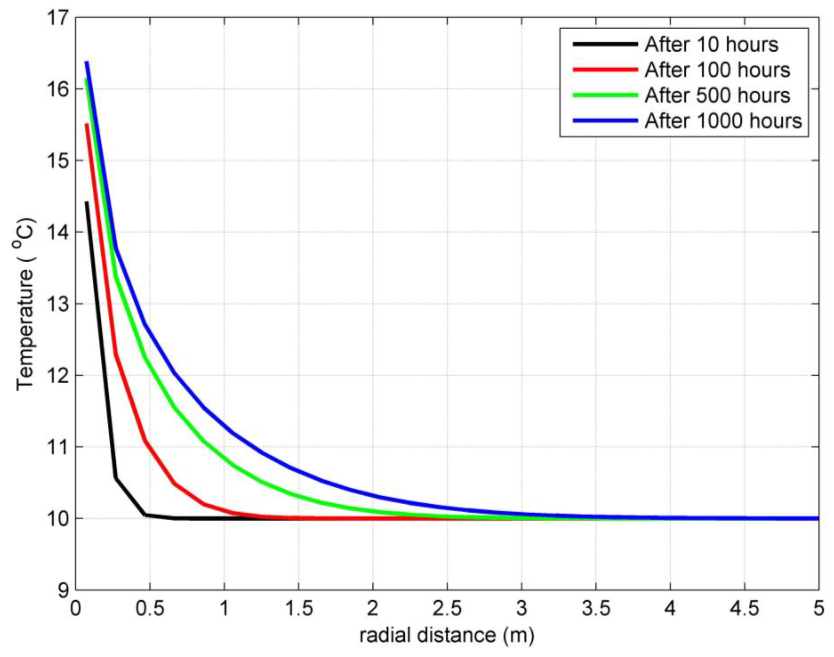
  • Considering the radial temperature change of the soil material, the temperature decreases exponentially outward along the radial direction. This is because heat is transferred from the hotter fluid in the U-tube to the soil nodes radially in the outward direction.
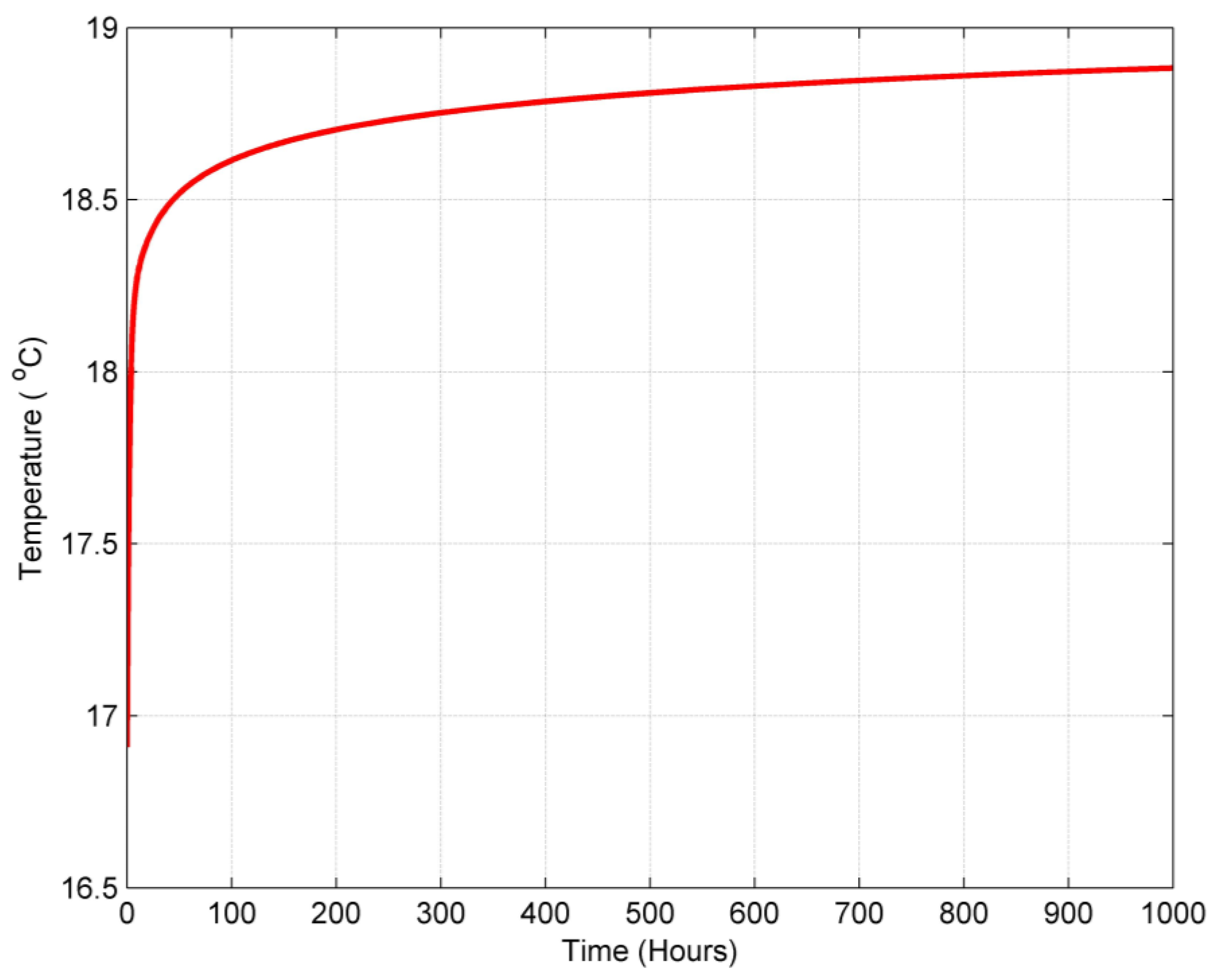
  • The temperature of the grout is higher than that of the borehole wall, as the position of the borehole wall is located in the outward direction of the grout node.
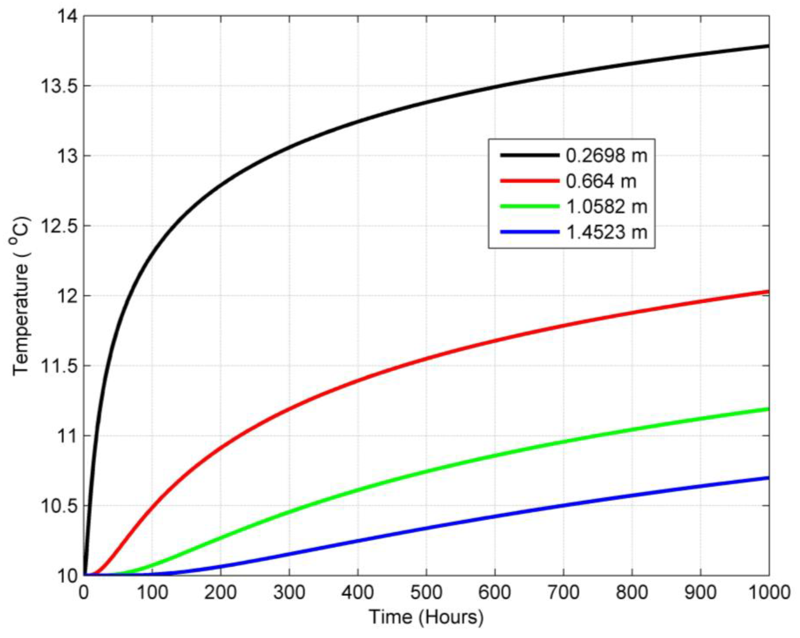
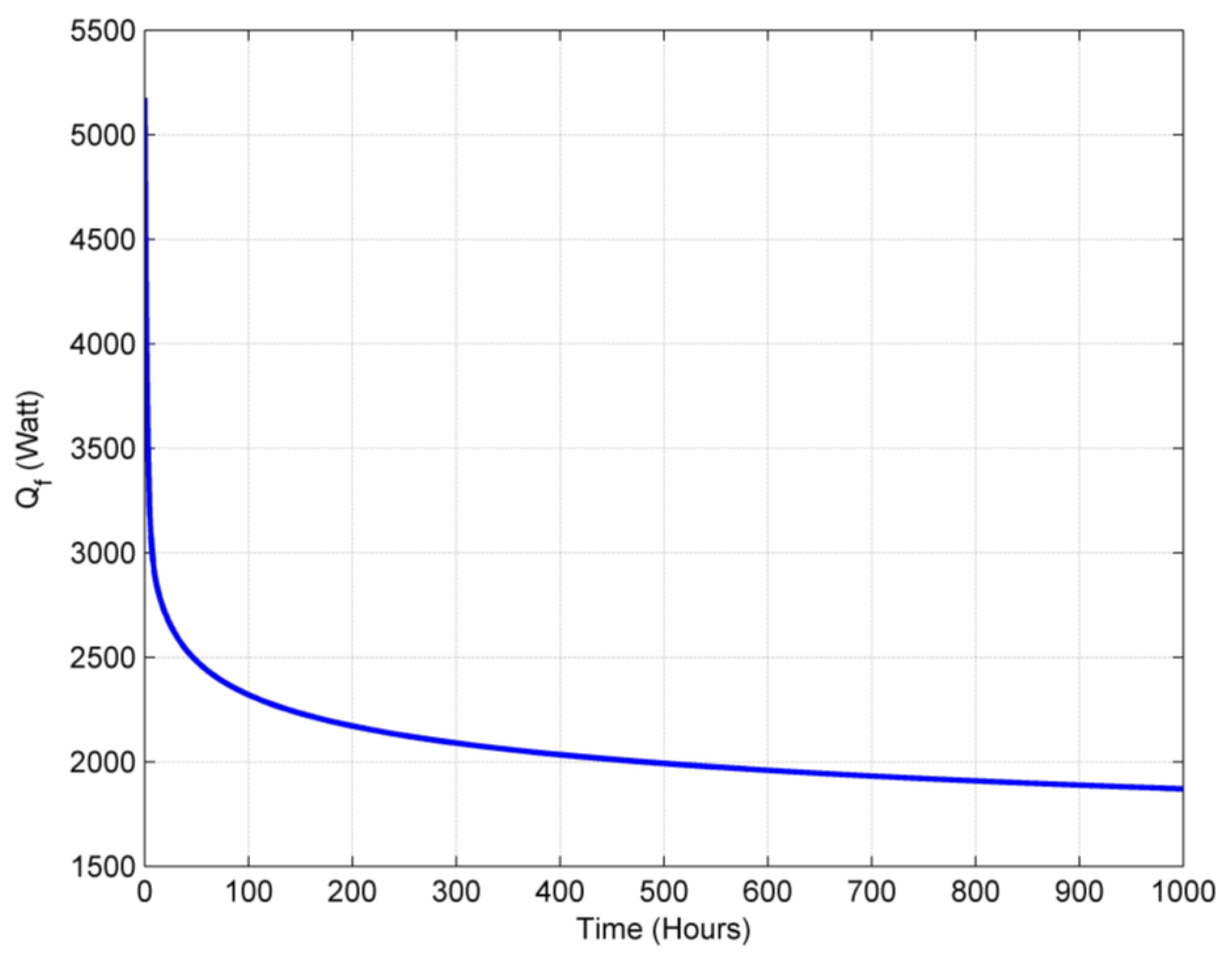
  • The heat transfer between the streaming fluid and the surrounding grout and soil materials decreases exponentially with time as the temperature difference between the inlet fluid temperature and the grout temperature decreases with time, while the temperature of the grout is elevated with the heating process.
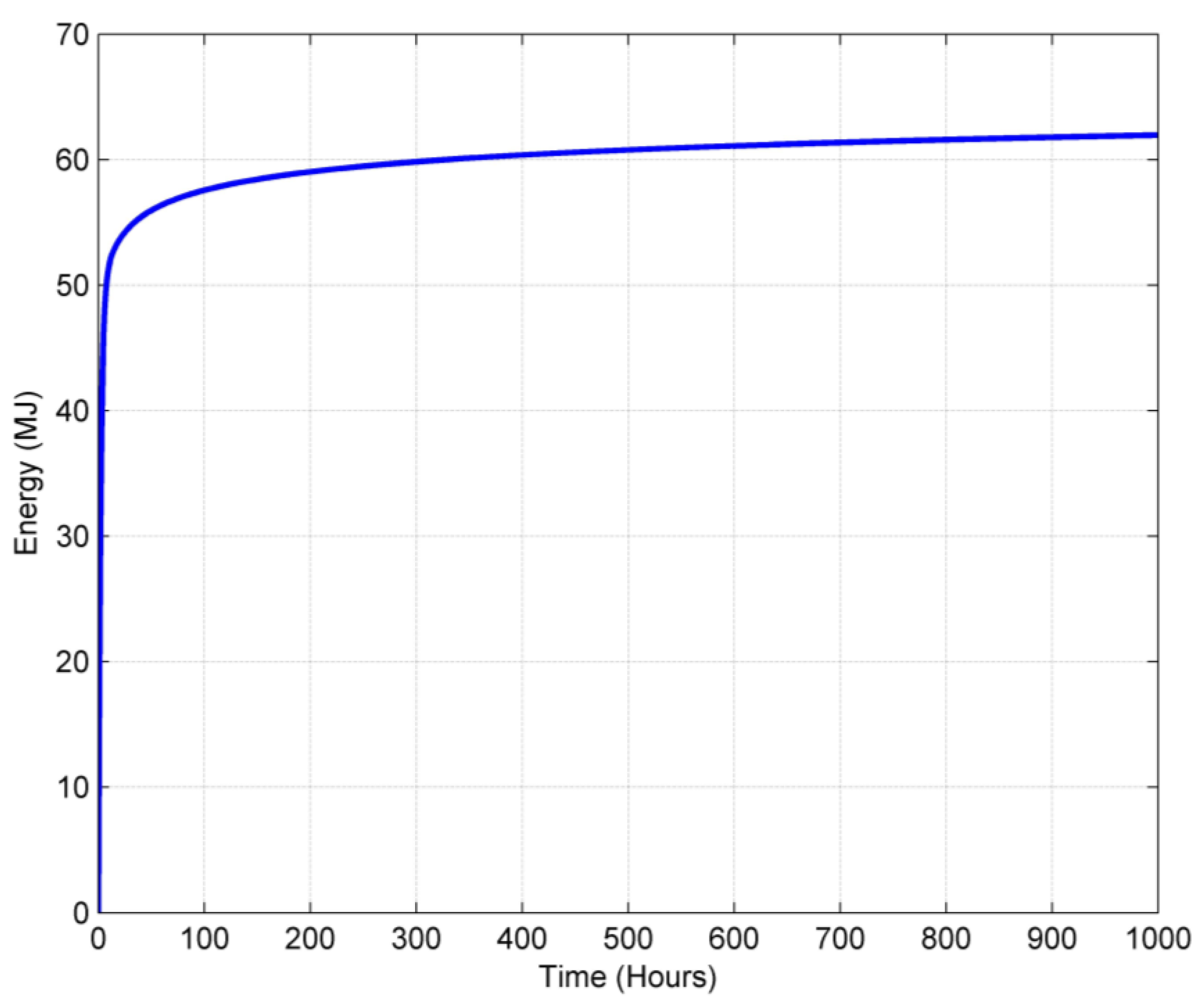
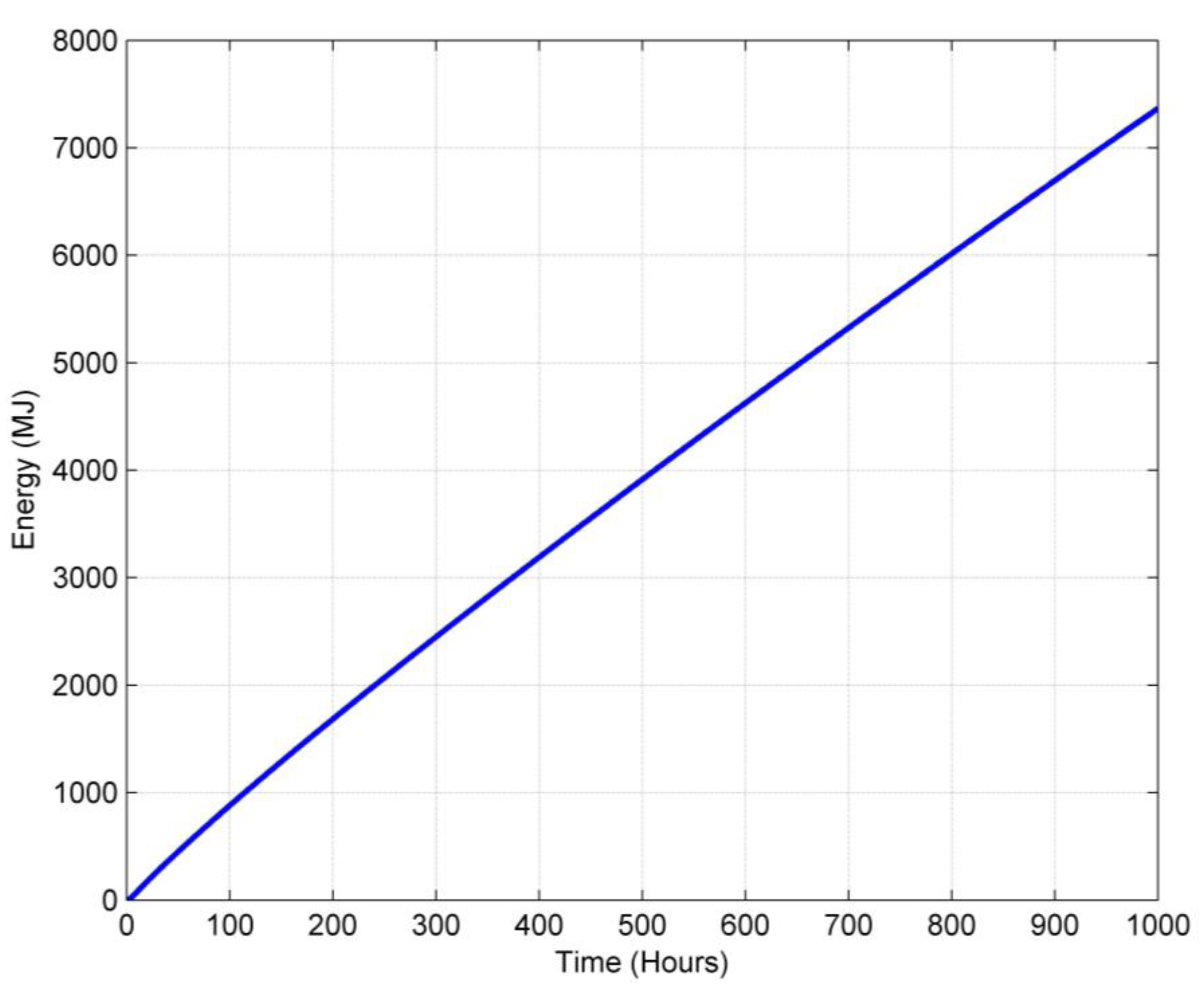
  • The energy storage of the grout material inside the borehole is only about 62 MJ, while the energy storage of the soil material outside the borehole reaches 7366 MJ after 1000 h of operation.
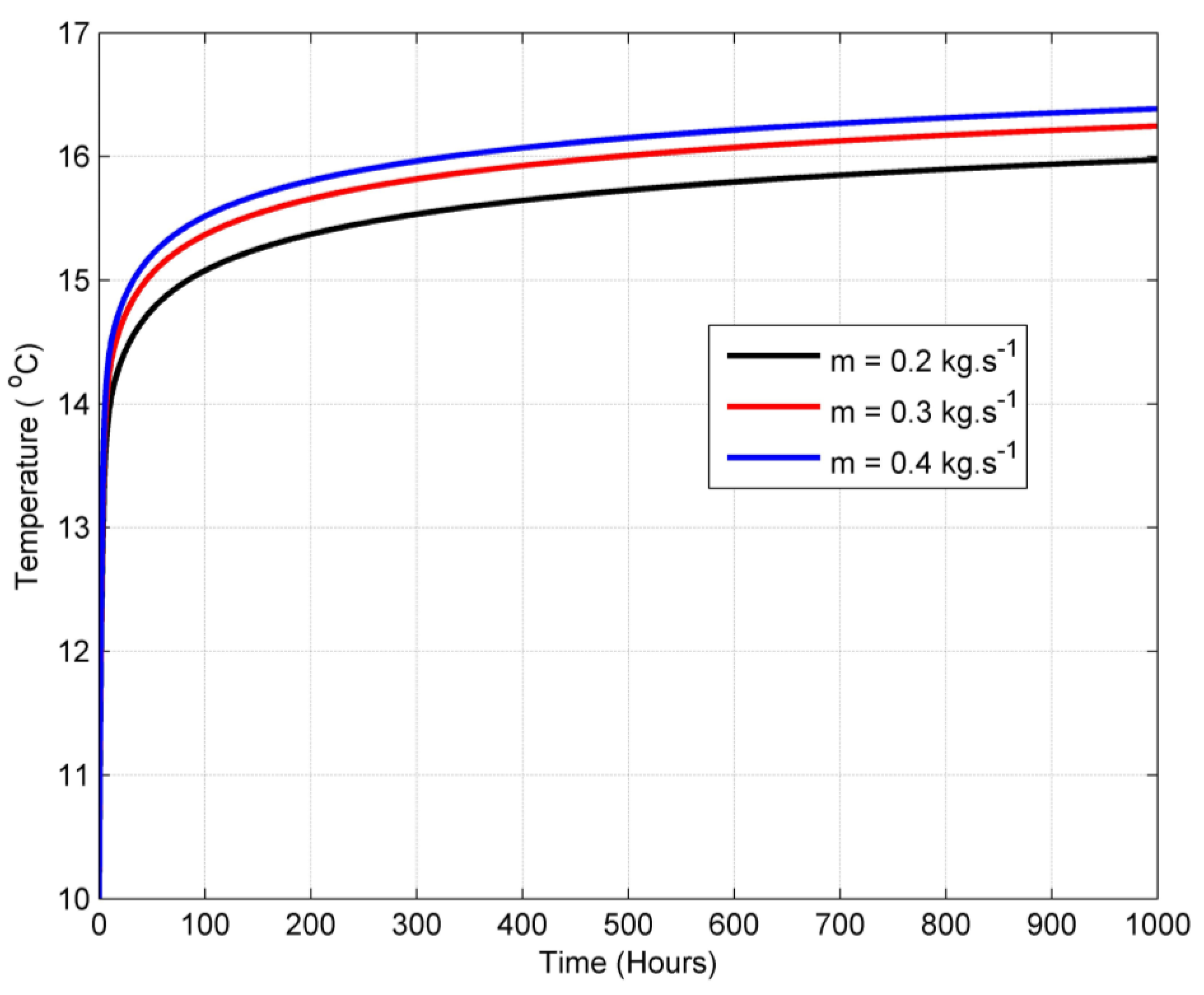
  • The heat transfer performance of the ground heat exchanger increases with the mass flow rate.
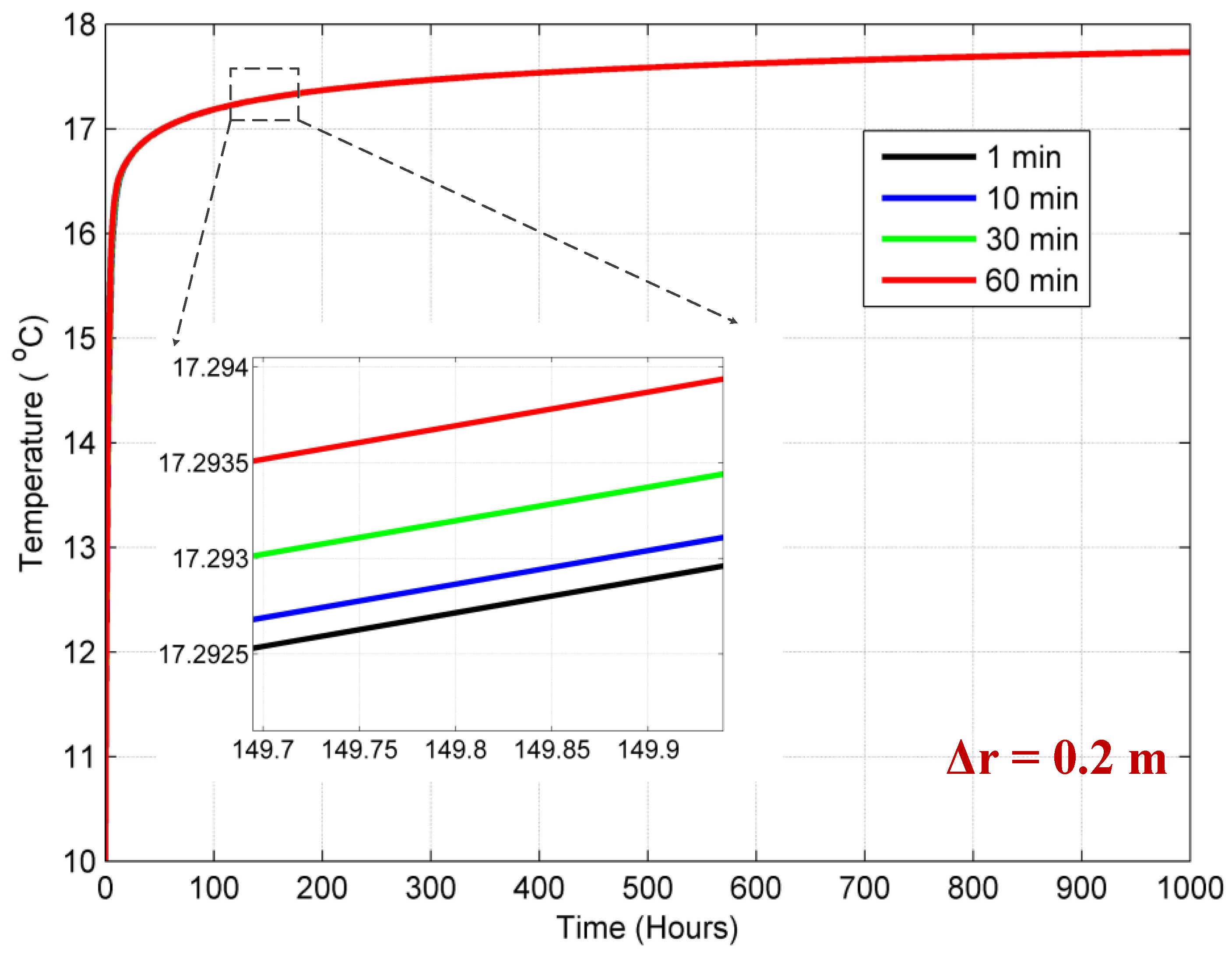
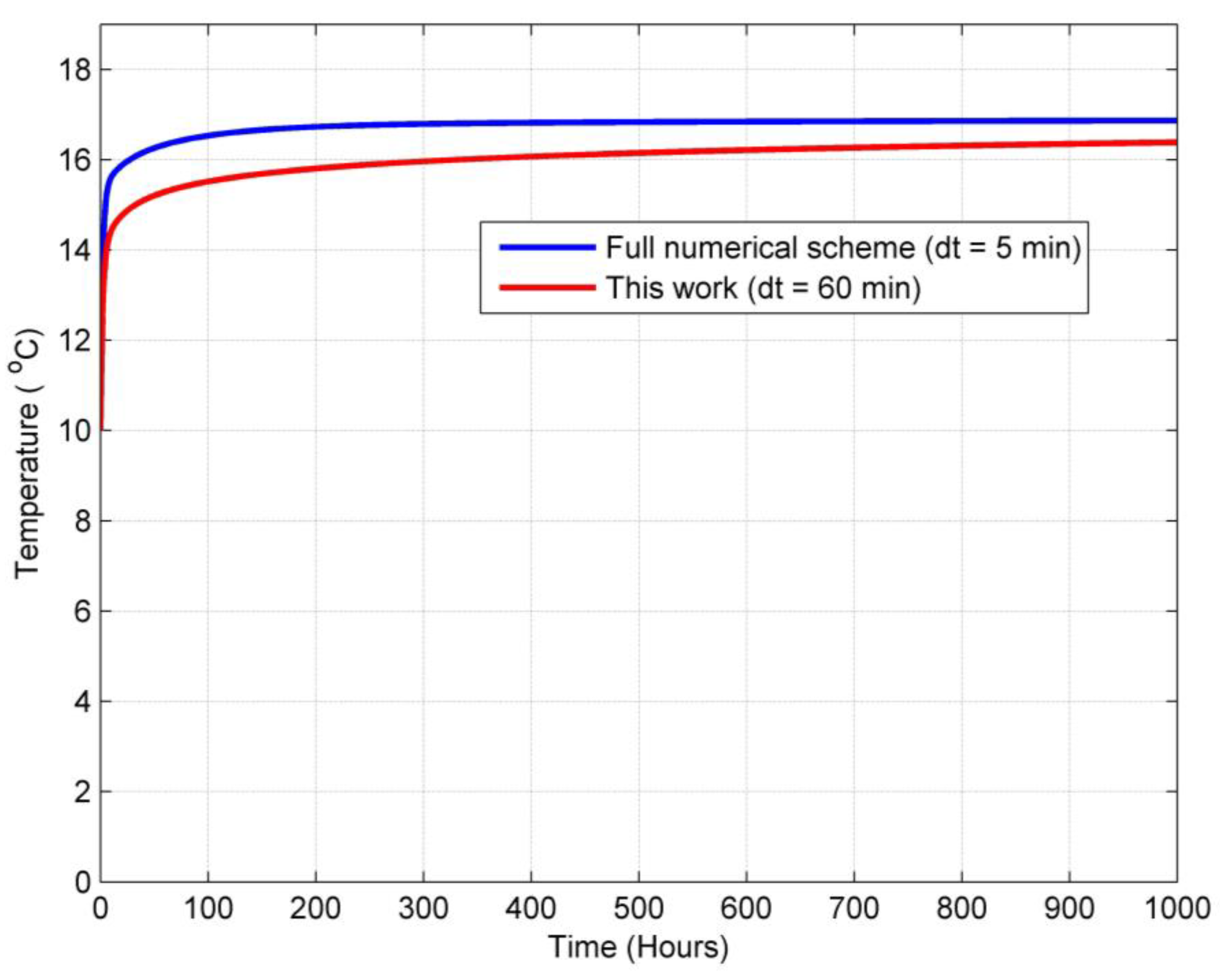
  • The suggested model is insignificantly sensitive to the change in time step. The sensitivity of the model is investigated with the grout temperature. There is only about a 0.001 °C difference as the time step changes from 1 min to 60 min.
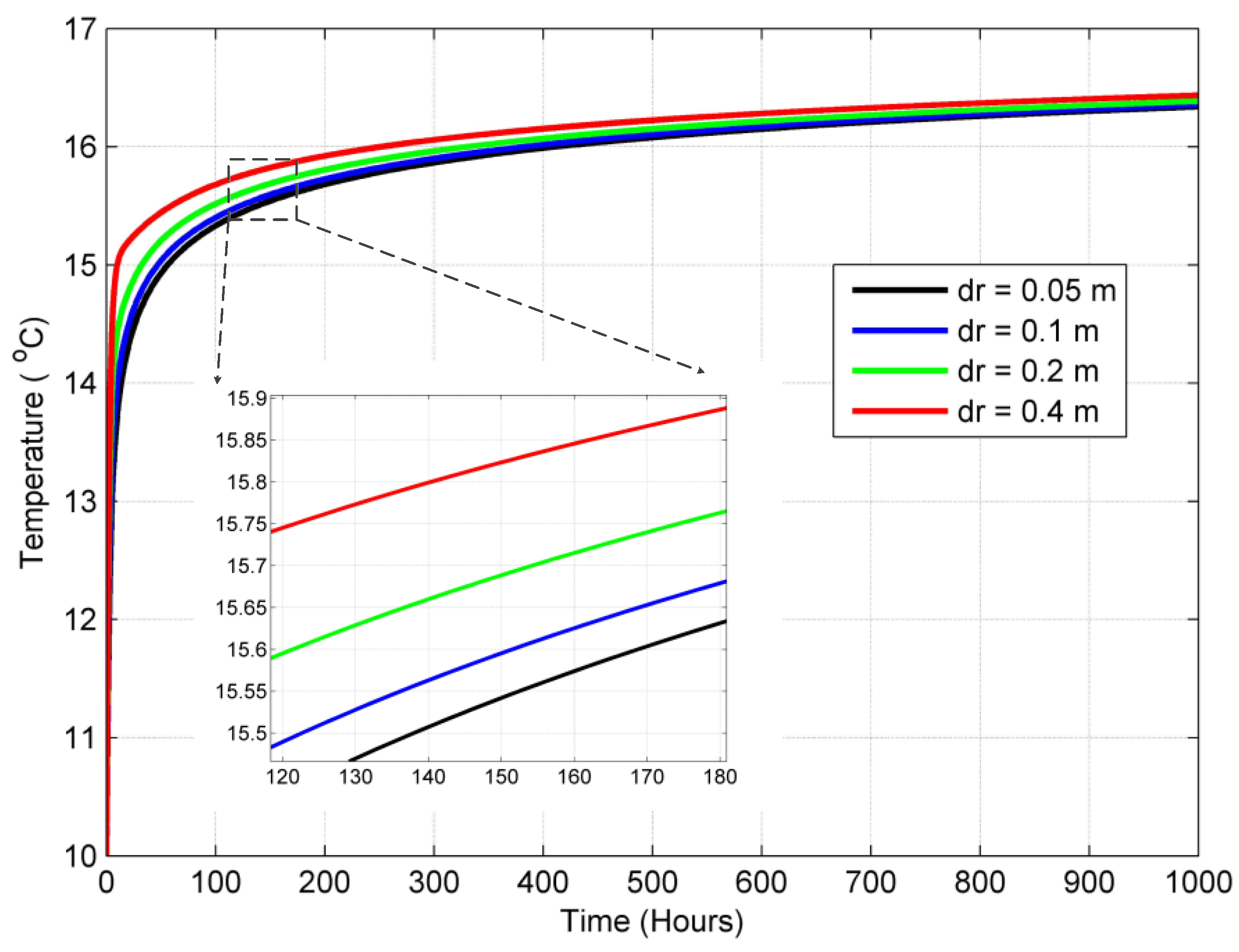
  • There is a small sensitivity in the model to the radial mesh size. The change in the borehole wall temperature can reach as high as 0.9 °C for a change in mesh size from 0.05 m to 0.2 m. The change in the borehole wall temperature can reach as high as 0.5 °C for a change in mesh size from 0.2 m to 0.4 m.
  • The suggested method is numerically efficient and stable compared to a full numerical scheme, and the solution can even converge for a large time step of 150 min.

Author Contributions

Methodology, E.M.S.; software, E.M.S.; validation, E.M.S. and E.D.K.; formal analysis, E.M.S.; writing—original draft, E.M.S.; writing—review and editing, E.D.K., W.H.L. and W.D.L.-S.; supervision, A.S.F. and W.H.L. All authors have read and agreed to the published version of the manuscript.

Funding

This research received no external funding.

Data Availability Statement

The original contributions presented in this study are included in the article. Further inquiries can be directed to the corresponding author.

Conflicts of Interest

The authors declare no conflicts of interest.

Nomenclature

c p : f Specific heat of the fluid in the U-tube
C g Thermal capacitance of the grout
C s , i Thermal capacitance of the ith soil node
D Half-shank spacing according to Figure 2
E g Thermal energy stored by the grout
E s Thermal energy stored by the soil
h i Convective coefficient of the fluid in the pipe
k b Thermal conductivity of the grout inside the borehole
k p Thermal conductivity of the pipe
k s Thermal conductivity of the soil outside of the borehole
m ˙ Mass flow rate of the fluid in the U-tube
P r f Prandtl number of the fluid inside the U-tube
Q f Heat transfer rate from the fluid to the grout node
R f b Thermal resistance between the fluid in the U-tube and borehole wall per unit length
R g b Thermal resistance between the grout and the borehole wall per unit length
R p U-tube pipe’s wall thermal resistance per unit length
R s , i Thermal resistance of the ith soil node
R e f Reynolds number of the fluid inside the U-tube
r b Radius of borehole
r p i Inner radius of U-tube pipe
r p o Outer radius of U-tube pipe
t Time
T b , w Temperature of the borehole wall
T f , i n Inlet fluid temperature
T f , 1 Temperature of the fluid in the down-running tube
T f , 3 Temperature of the fluid in the up-running tube
T g Temperature of the grout node
T O Undisturbed ground temperature
T s , i Temperature of the ith soil node
z Axial coordinate
Z Non-dimensional axial coordinate
Greek Symbols
ΔChange in
θ 1 Non-dimensional temperature in the down-running tube
θ 3 Non-dimensional temperature in the up-running tube

References

  1. Ma, J.; Wang, H.; Li, Y.; Ren, J.; Sun, H.; Du, S.; Wen, H. Heating and storage of medium-deep borehole heat exchangers: Analysis of operational characteristics via an optimized analytical solution model. J. Energy Storage 2024, 90, 111760. [Google Scholar] [CrossRef]
  2. Sharifishourabi, M.; Dincer, I.; Mohany, A. A novel trigeneration energy system with two modes of operation for thermal energy storage and hydrogen production. Energy 2024, 304, 132121. [Google Scholar] [CrossRef]
  3. Abu-Hamdeh, N.H.; Alsulami, R.A.; Aljinaidi, A.A.; Alazwari, M.A.; Eltaher, M.A.; Almitani, K.H.; Alnefaie, K.A.; Rawa, M.J.H.; Abusorrah, A.M.; Sindi, H.F.; et al. Numerical investigation of molten salt/SiO2 nano-fluid in the solar power plant cycle and examining different arrangements of shell and tube heat exchangers and plate heat exchangers in these cycles. J. Taiwan Inst. Chem. Eng. 2021, 124, 1–8. [Google Scholar] [CrossRef]
  4. Yao, B.; Salehi, A.; Baghoolizadeh, M.; Khairy, Y.; Baghaei, S. Multi-objective optimization of office egg shadings using NSGA-II to save energy consumption and enhance thermal and visual comfort. Int. Commun. Heat Mass Transf. 2024, 157, 107697. [Google Scholar] [CrossRef]
  5. Lu, Q.; Xie, P.; Lin, Y.; Liu, Y.; Yang, Y.; Lin, X. Hierarchical Power System Scheduling and Energy Storage Planning Method Considering Heavy Load Rate. Processes 2024, 12, 2725. [Google Scholar] [CrossRef]
  6. Skrzyniarz, M.; Morel, S.; Rzącki, J. Prediction of Chemical Composition of Gas Combustion Products from Thermal Waste Conversion. Processes 2024, 12, 2728. [Google Scholar] [CrossRef]
  7. Zhou, J.; Li, R.; Li, Y.; Shi, L. Aggregation Modeling for Integrated Energy Systems Based on Chance-Constrained Optimization. Processes 2024, 12, 2672. [Google Scholar] [CrossRef]
  8. Eletri, H.; Salilih, E.M.; Hamed, M.; Fellah, A. Performance analysis of a hybrid solar-driven cooler for refrigerator vehicle. Int. J. Refrig. 2023, 153, 281–295. [Google Scholar] [CrossRef]
  9. Nguyen, T.P.; Nguyen, T.N.; Ramadan, Z.; Park, C.W. Comparative study on thermal performance of two graphite fin thermal energy storages based on experiment, simulation, and artificial neural network. Int. Commun. Heat Mass Transf. 2024, 156, 107645. [Google Scholar] [CrossRef]
  10. Weng, T.; Zhang, G.; Wang, H.; Qi, M.; Qvist, S.; Zhang, Y. The impact of coal to nuclear on regional energy system. Energy 2024, 302, 131765. [Google Scholar] [CrossRef]
  11. Bakhshi, N.; Rashidi, S.; Rafee, R. Vertical coaxial ground heat exchangers with teeth and grooves on their outer pipes; a hydrothermal investigation. Appl. Therm. Eng. 2024, 243, 122570. [Google Scholar] [CrossRef]
  12. Giertl, T.; Vitázek, I.; Gaduš, J.; Kollárik, R.; Przydatek, G. Thermochemical Conversion of Biomass into 2nd Generation Biofuel. Processes 2024, 12, 2658. [Google Scholar] [CrossRef]
  13. Abdelhalim, A.M.; Meana-Fernández, A.; Suarez-Ramon, I. Integration of Thermal Solar Power in an Existing Combined Cycle for a Reduction in Carbon Emissions and the Maximization of Cycle Efficiency. Processes 2024, 12, 2557. [Google Scholar] [CrossRef]
  14. Jia, T.; Chen, H.; Zeng, X.; Zhu, Y.; Qin, H. Mitigating Risk and Emissions in Power Systems: A Two-Stage Robust Dispatch Model with Carbon Trading. Processes 2024, 12, 2497. [Google Scholar] [CrossRef]
  15. Žirgulis, G.; Javadi, H.; Chaudhari, O.A.; Ghafar, A.N.; Fontana, P.; Sanner, B.; Urchueguía, J.F.; Badenes, B.; Castell, J.M.C.; Shuster, M. Temperature evolution around four laboratory-scale borehole heat exchangers grouted with phase change materials subjected to heating–cooling cycles: An experimental study. J. Energy Storage 2023, 74, 109302. [Google Scholar] [CrossRef]
  16. Garau, M.; Torsæter, B.N. A methodology for optimal placement of energy hubs with electric vehicle charging stations and renewable generation. Energy 2024, 304, 132068. [Google Scholar] [CrossRef]
  17. Moreno-Leiva, S.; Haas, J.; Nowak, W.; Kracht, W.; Eltrop, L.; Breyer, C. Flexible copper: Exploring capacity-based energy demand flexibility in the industry. Energy 2024, 305, 132147. [Google Scholar] [CrossRef]
  18. Saeidi, R.; Karimi, A.; Noorollahi, Y. The novel designs for increasing heat transfer in ground heat exchangers to improve geothermal heat pump efficiency. Geothermics 2024, 116, 102844. [Google Scholar] [CrossRef]
  19. Cao, W.; Yu, J.; Xu, M. Optimization Scheduling of Virtual Power Plants Considering Source-Load Coordinated Operation and Wind–Solar Uncertainty. Processes 2024, 12, 11. [Google Scholar] [CrossRef]
  20. Salahodjaev, R.; Sadikov, A. Examining the Nexus Between Renewable Energy, CO2 Emissions, and Economic Factors: Implications for Countries Marked by High Rates of Coronary Heart Disease. Energies 2024, 17, 6057. [Google Scholar] [CrossRef]
  21. Abu-Hamdeh, N.H.; Salilih, E.M.; Alsulami, R.A.; Rawa, M.J.H.; Aljinaidi, A.A.; Alazwari, M.A.; Eltaher, M.A.; Almitani, K.H.; Abulkhair, H.A.; Alnefaie, K.A.; et al. The effects of incident solar radiation on the collector efficiency using coolant hybrid nanofluid via simulation of solar tower system with the parallel heat exchangers. J. Taiwan Inst. Chem. Eng. 2021, 124, 106–115. [Google Scholar] [CrossRef]
  22. Huang, S.; Li, Y.; Shi, X.; Bai, W.; Huang, Y.; Hong, Y.; Liu, X.; Ma, H.; Li, P.; Xu, M.; et al. The Role of Underground Salt Caverns in Renewable Energy Peaking: A Review. Energies 2024, 17, 6005. [Google Scholar] [CrossRef]
  23. Clemens, T.; Hunyadi-Gall, M.; Lunzer, A.; Arekhov, V.; Datler, M.; Gauer, A. Wind–Photovoltaic–Electrolyzer-Underground Hydrogen Storage System for Cost-Effective Seasonal Energy Storage. Energies 2024, 17, 5696. [Google Scholar] [CrossRef]
  24. Fan, M.; Cao, S.; Lu, S. Optimal allocation of multiple energy storage in the integrated energy system of a coastal nearly zero energy community considering energy storage priorities. J. Energy Storage 2024, 87, 111323. [Google Scholar] [CrossRef]
  25. Zhu, S.; Li, X.; Li, Y.; Sun, H.; Kang, X. Thermo-Mechanically Coupled Settlement and Temperature Response of a Composite Foundation in Complex Geological Conditions for Molten Salt Tank in Tower Solar Plants. Processes 2024, 12, 2602. [Google Scholar] [CrossRef]
  26. Zhao, C.; Duan, Q.; Lu, J.; Wang, H.; Sha, G.; Jia, J.; Zhou, Q. Coordinated Optimization Method for Distributed Energy Storage and Dynamic Reconfiguration to Enhance the Economy and Reliability of Distribution Network. Energies 2024, 17, 6040. [Google Scholar] [CrossRef]
  27. Zhang, Y.; Yang, X.; Zou, S.; Xu, X.; Tu, Y.; Tian, Y.; Ke, Z. Enhancing the phase change material based shell-tube thermal energy storage units with unique hybrid fins. Int. Commun. Heat Mass Transf. 2024, 157, 107763. [Google Scholar] [CrossRef]
  28. Szajding, A.; Kuta, M.; Cebo-Rudnicka, A.; Rywotycki, M. Analysis of work of a thermal energy storage with a phase change material (PCM) charged with electric heaters from a photovoltaic installation. Int. Commun. Heat Mass Transf. 2023, 140, 106547. [Google Scholar] [CrossRef]
  29. Liu, J.; Liu, Z.; Nie, C.; Li, Y. Design of combinational fins for a vertical shell-tube latent heat thermal energy storage unit. Int. Commun. Heat Mass Transf. 2023, 146, 106921. [Google Scholar] [CrossRef]
  30. Abu-Hamdeh, N.H.; Salilih, E.M. A case study in the field of sustainability energy: Transient heat transfer analysis of an ice thermal storage system with boiling heat transfer process for air-conditioning application. Energy Rep. 2022, 8, 1034–1045. [Google Scholar] [CrossRef]
  31. Pokhrel, S.; Amiri, L.; Poncet, S.; Ghoreishi-Madiseh, S.A. Reduced order 1 + 3D numerical model for evaluating the performance of solar borehole thermal energy storage systems. J. Energy Storage 2023, 66, 107503. [Google Scholar] [CrossRef]
  32. Uribe, D.; Vera, S.; Perino, M. Development and validation of a numerical heat transfer model for PCM glazing: Integration to EnergyPlus for office building energy performance applications. J. Energy Storage 2024, 91, 112121. [Google Scholar] [CrossRef]
  33. Vahidhosseini, S.M.; Rashidi, S.; Hsu, S.; Yan, W.; Rashidi, A. Integration of solar thermal collectors and heat pumps with thermal energy storage systems for building energy demand reduction: A comprehensive review. J. Energy Storage 2024, 95, 112568. [Google Scholar] [CrossRef]
  34. Kim, Y.; Dinh, H.; Kang, G.; Hoang, D. Performance evaluation of a novel horizontal ground heat exchanger: Coil-column system. J. Build. Eng. 2023, 76, 107180. [Google Scholar] [CrossRef]
  35. Meana-Fernández, A.; Suárez-López, M.J.; Blanco, E.; Prieto, J.; García, D. Experimental heating and cooling curves of the ground for temporary energy storage applications. J. Energy Storage 2024, 94, 112419. [Google Scholar] [CrossRef]
  36. Deng, Z.; Nian, Y.; Liu, Q.; Cheng, W. Numerical analysis of borehole heat exchanger using a single shape-stabilized phase change material in heating and cooling seasons. J. Energy Storage 2023, 70, 107897. [Google Scholar] [CrossRef]
  37. Shi, Z.; Zhang, C.; Cai, C.; Lu, X.; Liu, D. Comparative analysis of ground thermal conductivity and thermal resistance of borehole heat exchanger in different geological layered sequence. J. Build. Eng. 2024, 84, 108541. [Google Scholar] [CrossRef]
  38. Rajeh, T.; Al-Kbodi, B.H.; Li, Y.; Zhao, J.; Zhang, Y. Modeling and techno-economic comparison of two types of coaxial with double U-tube ground heat exchangers. Appl. Therm. Eng. 2023, 225, 120221. [Google Scholar] [CrossRef]
  39. Xu, Y.; Zeng, Z.; Sun, D. Experimental and numerical investigation on heat transfer characteristics of vertical ground heat exchangers in karst areas. Energy Build. 2022, 275, 112481. [Google Scholar] [CrossRef]
  40. Lein, R.; Fujii, H.; Ikeda, R.; Bina, S.M.; Harada, R.; Kosukegawa, H. Optimization of double layered horizontal directional drilled ground heat exchangers by water injection into the borehole. Geothermics 2024, 118, 102913. [Google Scholar] [CrossRef]
  41. Shoji, Y.; Katsura, T.; Nagano, K. Improvement of accuracy with uncertainty quantification in the simulation of a ground heat exchanger by combining model prediction and observation. Geothermics 2023, 107, 102611. [Google Scholar] [CrossRef]
  42. Ahmadfard, M.; Bernier, M. Simulation of borehole thermal energy storage (BTES) systems using simplified methods. J. Energy Storage 2023, 73, 109240. [Google Scholar] [CrossRef]
  43. Hosseinnia, S.M.; Sorin, M. Numerical approach for sizing vertical ground heat exchangers based on constant design load and desired outlet temperature. J. Build. Eng. 2022, 48, 103932. [Google Scholar] [CrossRef]
  44. Liu, Q.; Zhang, Y.; Luo, J.; Zheng, J.; Cheng, Y. Numerical study on heat transfer and flow characteristics of coaxial geothermal heat exchangers with helical finned inner tubes. J. Build. Eng. 2023, 65, 105752. [Google Scholar] [CrossRef]
  45. Guo, Y.; Huang, G.; Liu, W.V. A new semi-analytical solution addressing varying heat transfer rates for U-shaped vertical borehole heat exchangers in multilayered ground. Energy 2023, 274, 127373. [Google Scholar] [CrossRef]
  46. Guo, Y.; Zhao, J.; Liu, W.V. A novel solution for vertical borehole heat exchangers in multilayered ground with Robin boundary condition. Appl. Therm. Eng. 2024, 255, 123923. [Google Scholar] [CrossRef]
  47. Shen, J.; Zhou, C.; Luo, Y.; Tian, Z.; Zhang, S.; Fan, J.; Ling, Z. Comprehensive thermal performance analysis and optimization study on U-type deep borehole ground source heat pump systems based on a new analytical model. Energy 2023, 274, 127367. [Google Scholar] [CrossRef]
  48. Chen, W.; Zhou, C.; Huang, X.; Luo, H.; Luo, Y.; Cheng, N.; Tian, Z.; Zhang, S.; Fan, J.; Zhang, L. Study on thermal radius and capacity of multiple deep borehole heat exchangers: Analytical solution, algorithm and application based on Response Factor Matrix method (RFM). Energy 2024, 296, 131132. [Google Scholar] [CrossRef]
  49. Extremera-Jiménez, J.; Yousif, C.; Casanova-Peláez, P.J.; Cruz-Peragón, F. Fast segregation of thermal response functions in short-term for vertical ground heat exchangers. Appl. Therm. Eng. 2024, 246, 122849. [Google Scholar] [CrossRef]
  50. Li, M.; Tan, Y.; Wu, Y.; Wang, Q.; Li, Y. New algorithm for estimating parameters from interrupted thermal response tests of ground heat exchangers. Appl. Therm. Eng. 2024, 239, 122088. [Google Scholar] [CrossRef]
  51. Kerme, E.D.; Fung, A.S. Heat transfer simulation, analysis and performance study of single U-tube borehole heat exchanger. Renew. Energy 2020, 145, 1430–1448. [Google Scholar] [CrossRef]
  52. Kerme, E.D.; Fung, A.S. Transient heat transfer simulation, analysis and thermal performance study of double U-tube borehole heat exchanger based on numerical heat transfer model. Appl. Therm. Eng. 2020, 173, 115189. [Google Scholar] [CrossRef]
  53. Salilih, E.M.; Abu-Hamdeh, N.H.; Khoshaim, A.; Almasri, R.A.; Sajadi, S.M.; Karimipour, A. Thermal systems energy optimization employing two independent circuits of double vertical ground U-tube with PCM as the backfill material for building. J. Build. Eng. 2022, 56, 104752. [Google Scholar] [CrossRef]
  54. Salilih, E.M.; Abu-Hamdeh, N.H.; Oztop, H.F. Analysis of double U-tube ground heat exchanger for renewable energy applications with two-region simulation model by combining analytical and numerical techniques. Int. Commun. Heat Mass Transf. 2021, 123, 105144. [Google Scholar] [CrossRef]
  55. Zeng, H.; Diao, N.; Fang, Z. Heat transfer analysis of boreholes in vertical ground heat exchangers. Int. J. Heat Mass Transf. 2003, 46, 4467–4481. [Google Scholar] [CrossRef]
  56. Biglarian, H.; Abbaspour, M.; Saidi, M.H. A numerical model for transient simulation of borehole heat exchangers. Renew. Energy 2017, 104, 224–237. [Google Scholar] [CrossRef]
  57. Hu, P.; Yu, Z.; Zhu, N.; Lei, F.; Yuan, X. Performance study of a ground heat exchanger based on the multipole theory heat transfer model. Energy Build. 2013, 65, 231–241. [Google Scholar] [CrossRef]
  58. Yang, W.; Shi, M.; Liu, G.; Chen, Z. A two-region simulation model of vertical u-tube ground heat exchanger and its experimental verification. Appl. Energy 2009, 86, 2005–2012. [Google Scholar] [CrossRef]
  59. Abu-Hamdeh, N.H.; Salilih Elias, M. Numerical modelling of a parallel flow heat exchanger with two-phase heat transfer process. Int. Commun. Heat. Mass Transf. 2021, 120, 105005. [Google Scholar] [CrossRef]
  60. Minaei, A.; Maerefat, M. Thermal resistance capacity model for short-term borehole heat exchanger simulation with non-stiff ordinary differential equations. Geothermics 2017, 70, 260–270. [Google Scholar] [CrossRef]
  61. Lamarche, L.; Kajl, S.; Beauchamp, B. A review of methods to evaluate borehole thermal resistances in geothermal heat-pump systems. Geothermics 2010, 39, 187–200. [Google Scholar] [CrossRef]
Figure 1. Actual thermal resistance and capacitance network of a single-U-tube borehole heat exchanger.
Processes 12 02867 g001
Figure 2. Thermal resistance and capacitance network used for analytical modeling.
Processes 12 02867 g002
Figure 3. Thermal resistance and capacitance network used for numerical modeling.
Processes 12 02867 g003
Figure 4. Sensitivity of grout temperature to time step for a 0.2 m radial mesh size.
Processes 12 02867 g004
Figure 5. Sensitivity of borehole wall temperature to radial mesh size (Δr) for a 60 min time step.
Processes 12 02867 g005
Figure 6. Temperature profile of the fluid inside the U-tube for k s = 2 W·m−1·K−1, k b = 1 W·m−1·K−1, r p o / r b = 0.22, and D / r b = 0.29 [61].
Processes 12 02867 g006
Figure 7. Comparison of borehole wall temperature in this work against that obtained using full-scheme numerical technique.
Processes 12 02867 g007
Figure 8. Borehole wall temperature history with time using full numerical technique (a), and that in this work (b).
Processes 12 02867 g008
Figure 9. Temperature profile of the fluid in the U-tube along the borehole depth at different times, for a 0.4 kg·s−1 flow rate.
Processes 12 02867 g009
Figure 10. Radial temperature profile of the borehole wall and soil nodes at different times, for a 0.4 kg·s−1 flow rate.
Processes 12 02867 g010
Figure 11. Grout and borehole wall temperature history with time, for a 0.4 kg·s−1 flow rate.
Processes 12 02867 g011
Figure 12. Temperature profile with time for the soil nodes at different distances from the center of the borehole, for a 0.4 kg·s−1 flow rate.
Processes 12 02867 g012
Figure 13. Variation with time in the heat transferred from the fluid in the U-tube to the grout, for a 0.4 kg·s−1 flow rate.
Processes 12 02867 g013
Figure 14. Variation with time in the U-tube exit temperature, for a 0.4 kg·s−1 flow rate.
Processes 12 02867 g014
Figure 15. Variation with time in energy stored by grout, for a 0.4 kg·s−1 flow rate.
Processes 12 02867 g015
Figure 16. Variation with time in energy stored by soil nodes, for a 0.4 kg·s−1 flow rate.
Processes 12 02867 g016
Figure 17. Influence of mass flow rate on grout temperature profile.
Processes 12 02867 g017
Figure 18. Influence of mass flow rate on borehole wall temperature profile.
Processes 12 02867 g018
Table 1. Boundary conditions for the analysis.
Inlet condition T f , i n = T f 1 0   or   θ 1 0 = 1
Intersection of the down-running and up-running tubes T f 3 H = T f 1 H   or   θ 3 1 = θ 1 1
Table 2. Modeling parameter.
ParameterValue
H 100 m
r b 72.7 mm
r p o 16 mm
D36.7 mm
r p i 0.013 m
k s 1.5 W·m−1·K−1
k b 1.0 W·m−1·K−1
ρ s 2650 kg·m−3
ρ b 2650 kg·m−3
c p , s 2016 J·kg−1·K−1
c p , b 2016 J·kg−1·K−1
c p , f 4187 J·kg−1·K−1
T f , i n 20.0 °C
T O 10.0 °C
Initial temperatures of grout, soil, and borehole wall10.0 °C
Table 3. Time step and mesh size used in the modeling.
ParametersValue
Δ t (time step)3600 s
Δ r (mesh size of the soil outside of the borehole)0.2 m
Disclaimer/Publisher’s Note: The statements, opinions and data contained in all publications are solely those of the individual author(s) and contributor(s) and not of MDPI and/or the editor(s). MDPI and/or the editor(s) disclaim responsibility for any injury to people or property resulting from any ideas, methods, instructions or products referred to in the content.

