1. Introduction
The core is an important physical geological dataset to study and understand underground geology and mineral resources. The analysis of its lithology, phase mark, oil storage, and oil and gas content characteristics provides crucial information for the formulation of oilfield development and drilling strategies, the accurate evaluation of oilfield reserves, and the design of production plans. In oil and gas exploration and development, the use of ring core bits and other coring tools is the primary method for obtaining cores [
1,
2].
Long-barrel coring technology refers to coring operations in which the one-time coring length is more than two singles, and its length can reach 18 or 27 m, or longer. Its tools must contain multiple core barrels, which are typically used when the ground rock is well cemented and drillable. This coring method ensures a high core harvest rate, improves the single-barrel footage of coring as much as possible, and reduces coring costs. Long-barrels can be cored in a single pass to obtain sufficient lengths, and the coring efficiency can reach 2.5 to 3 times that of conventional coring techniques. In the case of suitable geological conditions, long-barrel coring can be carried out by choosing the appropriate number of core barrel connections, optimising the coring drill bit, and using rust-proof aluminium alloy inner barrels, according to the needs of the site, to improve the core quality [
3,
4,
5].
Compared to conventional coring tools, long-barrel coring tools have more complex downhole working conditions. According to the theory of compression bar stability in engineering mechanics, the longer the coring tool, the more easily it becomes unstable. During the core drilling process, the outer core barrel rotates. In addition to tension and stress, the force acting on the core barrel is the centrifugal force generated by rotation. The centrifugal force may intensify the bending and deformation of the core barrel, destabilise the coring process, cause the axis of rotation of the core barrel to deviate from the borehole axis, and lead to wear and destruction of the coring tool. At the same time, the core barrel is also subjected to other loads, such as torque, bending moment, and external extrusion downhole. Under different working conditions, the forces on each part are different. Therefore, the outer barrel tool of the long-barrel coring technology generally adopts a high-strength special seamless steel tube equipped with an outer barrel stabiliser to improve the stability, wear resistance, and strength of the tool. In addition, the threads of the coring tools are checked to ensure their safe use [
6].
In addition to the above factors affecting core stability, several additional challenges are associated with long-barrel coring in the field. For example, the improper selection of operating parameters can lead to an increase in the resistance of the core as it enters the core barrel, which in turn can lead to deformation, fracture, and breakage of the core, resulting in a series of core stability problems. Therefore, performing a core stability analysis under key operating parameters is important to guide the selection of parameters for the coring process in the field. However, most research has focused on the rock cutting mechanisms of coring PDC bits, often isolating a single PDC cutter as the study object and using overly simplified computational models and operational conditions. Moreover, existing studies lack large-scale investigations of rock fragmentation that consider the combined influence of both the bit and the core barrel in long-barrel coring processes. This prevents a fundamental understanding of the mechanical interaction mechanisms between long-barrel coring tools and cores with various lithologies. However, in practical scenarios, the interaction between the stability of the core and the coring tool is closely related. These interactions are critical factors contributing to core damage, sticking, and blockage. By establishing large-scale numerical models for full-bit coring under different lithological conditions, we can reveal the effects of various parameters on core stability, providing targeted guidance for improving coring processes and optimising tools.
For this purpose, numerical calculation models for tight, fractured, and broken cores were established using the explicit finite element method and discrete element method (DEM), respectively. Research was conducted on the stability of the core under different core lengths, rotational speeds, weights on bit, and well-inclined angles. Based on the vibration displacement and stress distribution characteristics of the core, the influence of various factors on the core stability was analysed. In addition, the coring process, cuttings distribution, and drill bit hydraulic characteristics were studied based on the CFD-DPM method. The results provide the necessary technical support for the design of long core barrels, coring operations, and exploration and development.
2. Constitutive Models and Mechanical Equations for Rocks with Different Geologies
2.1. The Rock Constitutive Model and Damage Criterion for the Process of a Tight and Fractured Core in the Barrel
In this study, the Drucker–Prager criterion was used to model the numerical calculation of tight and fractured cores; it is one of the most important strength theories in rock mechanics, which reflects the effects of volumetric stress, shear stress, and intermediate principal stresses on the strength of rocks [
7]. This is expressed as follows [
8]:
where
is the first invariant of stress, which is expressed as follows:
is the second invariant of stress, expressed as follows:
,
are material parameters related to the coefficient of internal friction
, expressed as follows:
In addition, to accurately describe the failure behaviour of rocks subjected to shear stress, the shear damage criterion was used [
9]. It states that the deformation of the rock is caused by the maximum shear stress, the equivalent plastic strain
at the damage is a function of the shear stress ratio
, the equivalent plastic strain rate
, and the fracture state variable
. This is expressed as follows:
where
is the equivalent plastic strain at the rock fracture; and
is the maximum shear stress, MPa.
2.2. The Mechanical Model of the Process of a Broken Core in the Barrel
In this study, the DEM is used to establish a numerical calculation model of the broken core. In a discrete element, the motion of each unit obeys the requirements of Newtonian mechanics and is governed by classical equations of motion [
10]. The equation describing the motion of the discrete cell method is the well-known Newton–Euler equation for the balance of forces and moments.
where
is the mass of discrete component object
i,
is the barycentre acceleration,
is vector force,
is the tensor moment of inertia,
is the angular acceleration,
is the angular velocity, and
is the moment vector. The mass and tensor of the inertial moment depend on the spatial distribution of the density
and inertial radius
and can be obtained by the following formula:
Typically, the forces and moments acting on a system include common physical forces (e.g., gravity) as well as the contact forces that are the most important in the calculation process, that is, the contact forces with other discrete elements, objects, or walls.
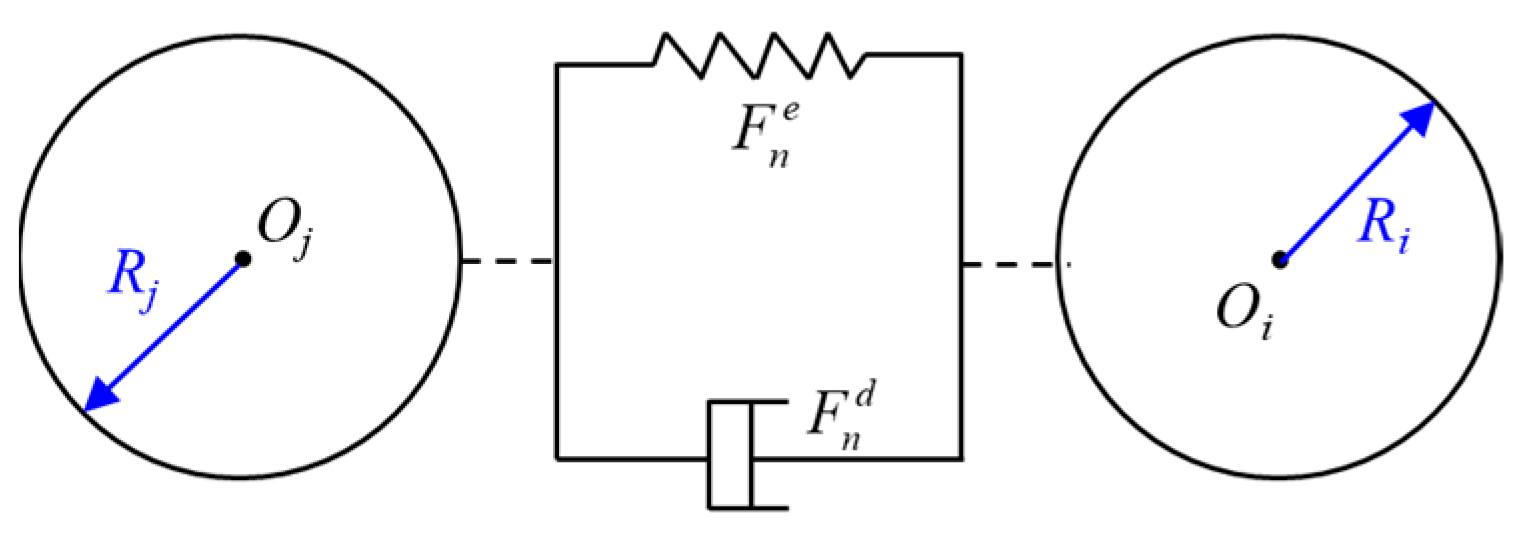
During the actual coring process of a broken core, relative displacement occurs between neighbouring rock blocks that collide with each other. In the specific model, each contact force is decomposed into tangential and normal parts, and each force can be modelled as an addition of the displacement–dependent (spring) elastic force and velocity–dependent dissipative force (damping).
Figure 1 shows the relationship between these contact forces [
11]. In this study, the Hertz contact theory [
12] was used to determine the contact force–displacement relationship in the normal direction of the model.
3. Establishment of Numerical Calculation Model
3.1. Establishment of Geometric Model
3.1.1. Tight Core Geometry Model
Three sizes of calculations were modelled as single-barrel (8.6 m), double-barrel (8.6 m + 9.2 m), and triple-barrel (9.2 m + 8.6 m + 9.2 m), respectively. The inner barrel diameter was 108 mm and the lengths were 8.6 m, 17.8 m, and 27 m, respectively, as shown in
Figure 2. To save the simulation calculation time, a certain length of the core columns was established at the initial moment of calculation, with lengths of 8.3 m, 17.5 m, and 26.7 m, respectively. The diameter of the core columns was 100 mm, and all cores were assumed to have entered the core barrel. In addition, a rock model with the dimensions 560 mm × 560 mm × 350 mm was established. After the calculation began, the core length gradually increased as the drill bit broke through the rock and the core continued to enter the barrel.
3.1.2. Fractured Core Geometry Model
The cross section of the core at the fracture site is complex and varied. To facilitate the calculation, we selected the typical fracture form, i.e., an oblique core section. To study the influence of the fractured core on the stability of the core during the coring process, as shown in
Figure 3, we assumed that part of the core entered the core barrel and that the core had fractured into four sections. The drill bit, inner barrel, and core column rock were modelled and assembled. A total of three fractures were present in the core column to simulate the fractured core. The remaining model parameters were consistent with the tight single–barrel simulation model. Similarly to the tight core model, a core model with a total length of 8.3 m was established at the initial moment, and as the drill bit broke through the rock, the core length gradually increased and continued to enter the core barrel.
3.1.3. Broken Core Geometry Model
During the coring process, some of the cores broke and formed a crushed section in the barrel, which was caused by the rock geological conditions and drilling parameters. To study the influence of the broken core in the barrel on subsequent coring, we used the DEM to model the broken core. The DEM analysis of the broken core in the barrel is shown in
Figure 4a. To simulate the broken core more realistically, an irregular four-grain assemblage was used for the rock, as shown in
Figure 4b. The simulation was performed after setting the downward and rotational speeds of the drill.
3.2. Meshing
In the finite element method, the mechanical calculation of the core is mainly realised by solving the solid mesh; however, in the discrete element method, it is realised by solving the interparticle mechanical properties. Therefore, only tight and fractured cores need to be meshed.
A C3D8R eight-node linear hexahedral mesh [
13] was used for the fractured and tight cores, and the mesh was encrypted in the middle of the rock mass, as shown in
Figure 5 and
Figure 6. Because the shape of the drill bit is complex and deformation is not considered, the mesh is a C3D10M ten-node modified quadratic tetrahedral cell, and a second-order tetrahedral mesh was used to ensure solution accuracy.
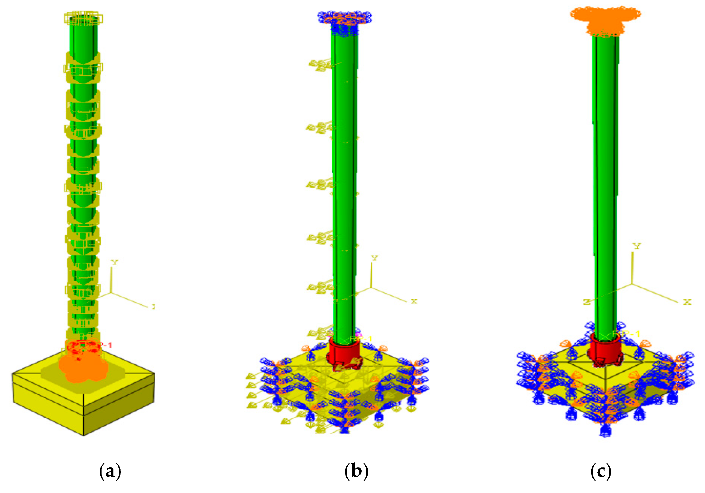
3.3. The Boundary Conditions
Generic face-to-face contact was used for rock–rock, rock–tool wall, and core barrel–bit contact behaviours. The contact property was “hard” contact in the normal direction. The tangential direction was frictional contact with a friction coefficient of 0.2 [
14]. Considering that the strength of the polycrystalline diamond compact (PDC) coring bit was much higher than that of the rock, the bit was set as a rigid body, and the deformation of the bit was not considered. By defining the RP point and applying a weight to bit and rotational speed, gravitational acceleration was also added to consider the effect of the well inclination. Combined with the actual long-barrel coring process, the bottom surface of the rock block was set to be completely fixed, and the core was unrestricted, allowing the drill bit to move only in the direction of the applied pressure, as shown in
Figure 7.
3.4. Parameter Setting
In the calculation model for tight and fractured cores, a typical tight rock was selected for the rock properties. The core barrel material was set as steel, and the ideal elastic–plastic material model was used in ABAQUS. The material parameters are listed in
Table 1 [
15].
The calculation of broken cores was mainly performed using the DEM, which involves the contact parameters between discrete rock fragments and rock property parameters in the model. The detailed parameter settings are listed in
Table 2 [
16].
Based on the parameters of the long-barrel coring tools provided onsite, the working condition parameters for the simulation were set, as listed in
Table 3.
3.5. Basic Assumptions
The long-barrel coring operation is a highly complex rock-breaking process. When simulating and analysing the coring process of the PDC coring drill bit, the following assumptions were made for the calculation model to shorten the convergence time of the simulation, improve the feasibility of the calculation, and neglect the influence of secondary factors:
- (1)
The cutting edge of the PDC coring bit is a thin layer of polycrystalline diamond, whose hardness and strength are much greater than those of the rock [
17], and the cutting teeth and PDC coring bit are set as rigid bodies in the simulation process.
- (2)
Constant velocity and weight of the bit acting on the cutting teeth and bit.
- (3)
The rock was a continuous homogeneous medium and the effect of the rock pore pressure was not considered.
- (4)
The influence of the rock unit after failure, that is the rock chips generated by cutting, on the drilling process was neglected.
- (5)
The influence of temperature change and cutting teeth wear on the performance of the PDC coring drill bit was not considered.
- (6)
The effect of rock confining pressure [
18].
4. Results and Discussion
4.1. Analysis of Factors Influencing Stability of Tight Cores
4.1.1. Influence of Rotation Speed
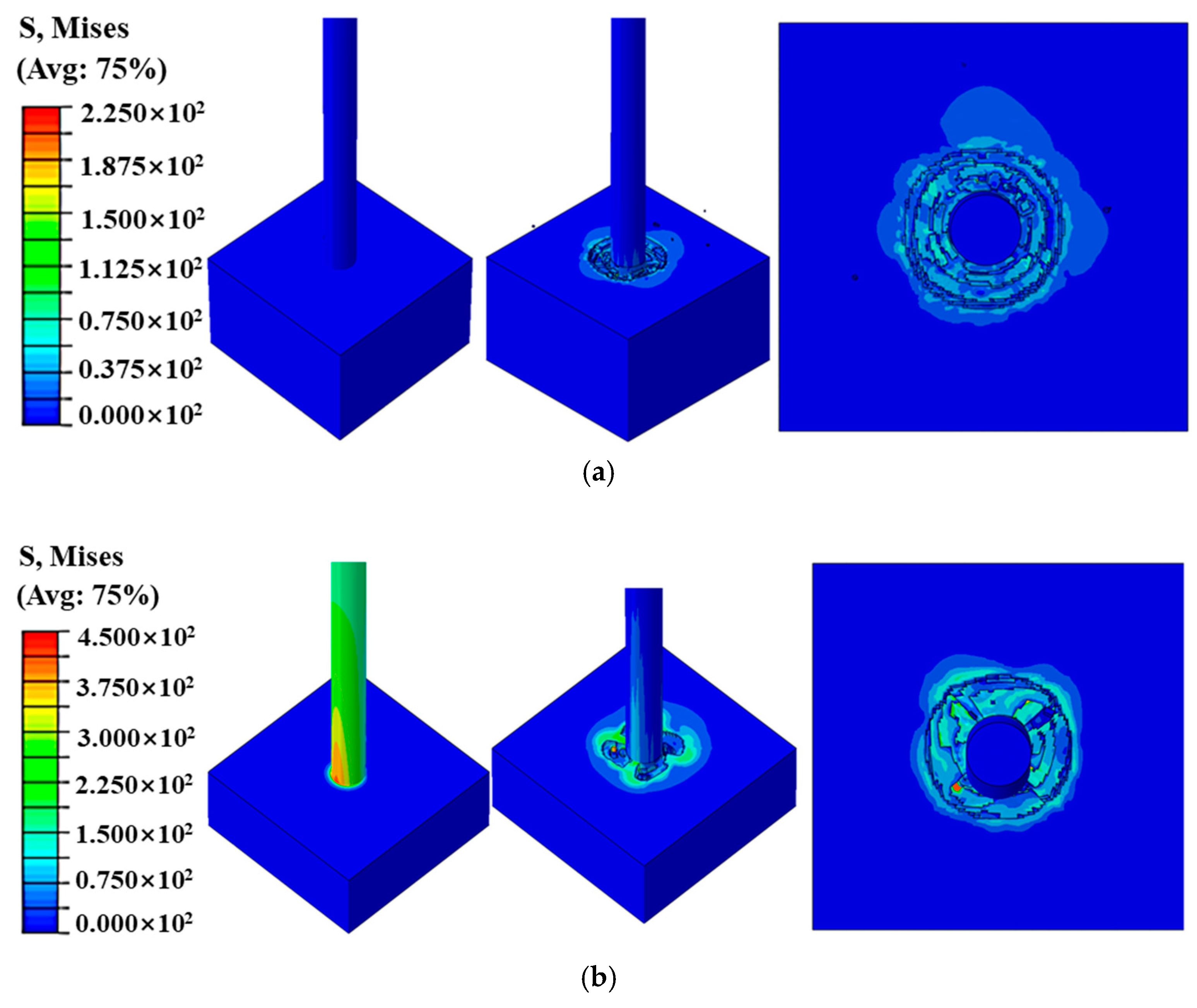
In the tight rock coring process, the stress on the core varied significantly with the fluctuation in the rotational speed, and with the increase in the rotational speed of the drill bit, the rock in the contact area with the drill bit exhibited a local stress concentration phenomenon, as shown in
Figure 8a–c. In contrast to the same moment, the higher the rotational speed, the larger the stress will gradually become, and when the rotational speed suddenly increases, it will lead to the instability of the core column–core block and the possibility of fracture, plugging, and jamming.
Figure 9a–c shows the time course of the transverse displacement of the centre point of the core at rotational speeds of 45, 52, and 60 rpm, respectively, and
Figure 9d shows a comparison of the average values of the
X-axis and
Z-axis vibration displacements at different rotational speeds. Comparing the mean values of the core displacements in
Figure 9a–c indicates that the higher the rotational speed of the drill bit, the higher the transverse displacement of the centre point of the core. As observed in
Figure 9d, in the range of 45–60 rpm, the average displacement value of the
X-axis was higher than that of the
Z-axis at low rotational speeds, and when the rotational speed increased, the vibration amplitude of the
Z-axis was greater than that of the
X-axis. Further analysis showed that the increase in the rotational speed directly affected the stability of the top of the core, which in turn caused vibration, resulting in the core colliding with the wall of the inner barrel, generating friction, and destroying the morphology of the core. Therefore, in actual coring operations, a higher tool rotation speed is not necessarily better. Maintaining a drill string rotation speed around 52 RPM can effectively reduce core vibrations thereby enhancing core stability. Therefore, before the actual coring drilling, the appropriate rotational speed of the drill should be set to increase the drilling speed and ensure the coring rate.
4.1.2. Influence of Weight on Bit
Figure 10a–c shows a comparison of the stress cloud at the bottom of the core under three sets of different weights on bit, which indicates that at the same moment, the higher the weight on bit, the greater the stress suffered by the bottom of the core. The location of the maximum stress in the core was also different, but all of them occurred at the point where the cutter flank of the drill bit contacts the core. The top views in
Figure 10a–c clearly show that the core is not a perfect circle, with increasing deviation from the centre as the weight on bit (WOB) increases. Additionally, the von Mises stress analysis reveals that as WOB increases, the stress exerted on the core also rises. This stress increase is a critical factor causing core vibration and has a significant impact on core stability.
Figure 11a–c shows the time course diagrams of the change in transverse displacement at the centre of the core when the bit weight was 5 t, 6.5 t, and 8 t, respectively, and
Figure 11d shows the comparison of the average values of the
X-axis and
Z-axis vibration displacements under different weights on bit. A comparison of the average values of the transverse displacements of the core top in
Figure 11a–c shows that the larger the weight on the drill bit, the smaller the transverse displacements of the centre point of the core.
Figure 11d depicts that in the range of weight on bit of 5–8 t, with an increase in weight on bit, the vibration amplitude of the top of the core in the direction of the
X-axis decreases rapidly compared with that of the
Z-axis, but the average value of the vibration amplitude is always higher than that of the
Z-axis. In summary, an increase in the weight on bit reduces the vibration amplitude of the core, which improves the stability of the core in the barrel. Therefore, in actual coring operations, increasing the weight on bit (WOB) can help reduce the risk of core fracture during drilling. We recommend that the weight on bit should not be less than 6.5 tons during coring operations, as this can effectively dampen core vibrations and thereby improve core stability.
4.1.3. Influence of Well Inclination Angle
Figure 12a–c shows the stress cloud at the bottom of the core for three sets of different well inclination angles, respectively; the larger the well inclination angle, the smaller the stress suffered by the bottom of the core, and the maximum stress occurred at the point where the cutter flank of the drill bit contacted the core. The top views in
Figure 12a–c clearly show that the core is not a perfect circle, with greater deviation from the centre as the well deviation angle increases. This directly leads to increased frictional contact and collisions between the core and the core barrel.
Figure 13a–c shows the time course of the change in the transverse displacement of the core centre point when the well inclination angles were 40°, 50°, and 60°, respectively, and
Figure 13d shows a comparison of the mean values of the X- and
Z-axis vibration displacements at different well inclination angles. By comparing the mean values of the core displacements in
Figure 13a–c, the larger the well inclination angle, the larger the transverse displacement of the core centre point. As depicted in
Figure 13d, in the range of a well inclination angle of 4060°, an increase in the well inclination angle intensifies the vibration displacement of the core top in the directions of the
X- and
Z-axes, and the mean value of the displacement along the
X-axis is always larger than that along the
Z-axis. Therefore, the inclination angle is another key factor affecting the stability of the core, which directly leads to an increase in friction between the core and inner barrel, destroying the core. Therefore, in actual coring operations, it is essential to control the well deviation angle appropriately. An optimal well deviation angle can effectively suppress core vibrations thereby enhancing core stability. According to the calculation results, the deviation angle should not exceed 50°.
4.1.4. Influence of Shaft Length
Figure 14a,b present a comparison of the stress clouds at the bottom of the core column at the initial moment under single-barrel and double-barrel conditions, respectively. As observed in
Figure 14a, the bottom of the core column in a single-barrel does not exhibit more obvious stress changes; however,
Figure 14b demonstrates that the bottom of the core column exhibits obvious stress changes when the double-barrel is considered for coring. By comparing the overhead view of the top of the core, the twisting of the core barrel is observed to be more obvious under the double-barrel condition, which indicates that the longer the well barrel, the easier it is to lead the contact between the core and the barrel wall, which generates greater friction and may fracture the core, leading to jamming and plugging of the core. Although long-barrel coring improves single-trip coring efficiency to some extent, the increased core length significantly reduces core stability. In long-barrel coring, the core is more prone to deformation, with increased friction and collisions occurring between the core and the core barrel. Therefore, in practical drilling operations, structural optimisation of the core barrel is recommended when applying long-barrel coring to reduce the interaction forces between the core and the barrel.
4.2. Analysis of Factors Influencing Stability of Fractured Cores
Taking a single-barrel core column of 8.6 m, 45 rpm, 5 t bit weight, and 60° inclination angle as an example, the core stress diagram in
Figure 15 indicates that the core column is affected by the inclination of the well at 60° and the torque generated by the drill bit, which produces vibration and shaking, collides with the wall of the inner barrel, and generates friction. An in-depth analysis of the diagram reveals that additional stress concentration and dislocation occurs in the fractures (the area marked by the red circle in the figure). Over time, the phenomenon of core jamming and plugging occurs, which affects the harvest rate of the core. Therefore, in actual coring operations, the rate of penetration (ROP) should be continuously monitored. A sudden, significant decrease in ROP sustained over a period may indicate potential core breakage or fracturing, which could lead to core jamming and related issues. Monitoring ROP trends also allows for the real-time assessment of the core’s condition during coring, providing valuable guidance for optimising the coring process.
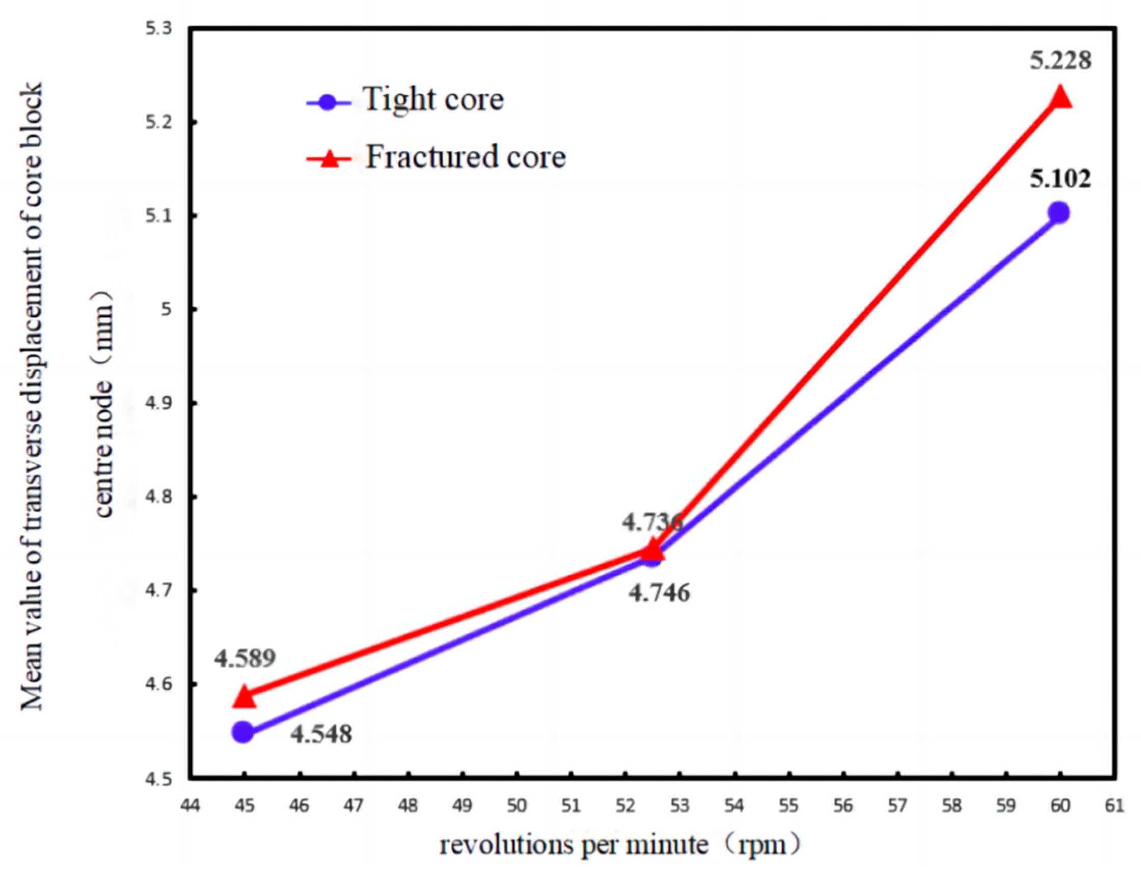
4.2.1. Influence of Rotational Speed
Similarly to the analysis method of the tight core, the transverse displacement data at the origin of the top of the core column was recorded, and its mean value was recorded and collated with the working condition data.
Figure 16 illustrates the relationship between stability and rotational speed for tight versus fractured cores, indicating that the stability of the fractured core entry into the barrel is poorer than that of the tight core, but both produce more violent transverse displacement with the increase in rotational speed, which worsens stability. Therefore, in actual coring operations, when drilling through fractured formations or when core breakage occurs, the rotation speed of the drill string should be reduced to prevent the excessive vibration of the core.
In engineering, a change in rotational speed is commonly used to judge the operation of coring. For example, when the rotational speed suddenly increases, the torque tends to be stable, and the phenomenon of core wear may occur. When the weight on bit does not return, the drilling speed slows down, indicating a high probability of plugging; thus, when the drilling process occurs once the rotational speed suddenly changes, corresponding measures should be taken immediately to ensure the stability of the core drilling.
4.2.2. Influence of Weight on Bit
Figure 17 illustrates the relationship between stability and weight on bit for tight and fractured cores, which indicates that the stability of the fractured core in the barrel is poorer than that of the tight core, but both increase the transverse displacement and reduce the stability as the weight on bit decreases. Therefore, during slight jamming of the core, the weight on bit can be increased appropriately to improve stability. However, a high drilling overpressure can easily lead to the bending of the core barrel, which in turn leads to the bending of the core column, making it more difficult for the core to enter the barrel and increasing the probability of plugging. The severity of core plugging depends on rock fragmentation and the matching of the drilling parameters [
19].
Therefore, selecting the appropriate weight on bit is the key to ensuring the stability of the core in the barrel, and once plugging and jamming occur, the weight on bit should be reduced immediately to quickly remove the concentrated stress, make the inner barrel run stably, and improve the rate of core acquisition.
4.2.3. Influence of Well Inclination Angle
Figure 18 illustrates the relationship between the core stability and well inclination angle for tight and fractured cores, showing that the stability of the fractured core in the barrel is poorer than that of the tight core, and both decrease with the increasing well inclination angle, producing more transverse displacement. Therefore, during drilling and coring operations, the well inclination angle should be designed in advance to improve stability and increase the yield rate.
4.3. Analysis of Factors Influencing Stability of Broken Cores
The coring process in a broken formation, which is affected by both the nature of the rock and the stability of the tool, is highly prone to serious plugging and jamming phenomena, which, if not detected in time or if the drill bit is not raised in time after detection, will lead to core wear [
20] and reduce the coring harvest rate.
Figure 19 shows the pressure cloud map as well as the angular velocity cloud map of the broken core coring process. The pressure concentration can be seen occurring near the teeth of the PDC drill bit, which is because of the rapid extrusion of the broken rock at the bottom and the resulting expansion. In addition, the simulation demonstrates the process of the drill bit crushing the broken rock into a tight crushed body and the crushed body entering the gap, which causes the rock and barrel wall to produce a large amount of friction, which is the direct cause of plugging and jamming.
Regarding broken core plugging and jamming, engineering can use the method of adding a liner to the original inner barrel so that it can be pushed out together with the core when the core is released.
4.4. Hydraulic Characteristics and Cuttings Carrying Analysis of Coring PDC Drill Bit
As shown in
Figure 20, it is a cloud diagram of the cuttings concentration at different nozzle angles at the same position. It can be seen from the figure that when the nozzle angle is 6°, the concentration of the cuttings near the cutters is the largest, and when the nozzle angles are 7°, 9°, and 10°, the concentration of the cuttings particles near the cutters is smaller, indicating that the flow of fluid in this area is relatively sufficient. When the nozzle angles are 8° and 10°, the concentration of the cuttings on the outside of the blade, the flow channel and the area occupied by the cuttings are larger. From the overall perspective of the drill bit, as the nozzle inclination angle increases, the range and intensity of hydraulic flushing increase, and the cuttings accumulate less, until the cuttings accumulate more at 10°. As shown in
Figure 21, the average cuttings concentration on the drill bit and on most blades is the lowest when the nozzle angle is 9°. Therefore, in general, the flushing effect is best when the nozzle angle is 9°. In actual coring operations, failure to promptly remove cuttings can lead to accumulation at the contact point between the core and the bit. This buildup significantly increases frictional resistance, accelerates core wear, and can even result in core breakage. Therefore, optimising the hydraulic structure of the coring PDC bit can effectively enhance the efficiency of cuttings removal at the bottom hole.
5. Conclusions
In this study, the influence of rotational speed, barrel length, weight on bit, and well inclination angle on the stability of coring in different rocks were analysed using numerical simulations, and the results of the analysis of the factors influencing the core stability of three types of rocks, namely tight, fractured, and broken, were obtained.
(1) For tight core drilling, the increase in rotational speed, increase in weight on bit, and decrease in the well inclination angle will increase the stress on the bottom of the core, whereas the decrease in rotational speed, increase in weight on bit, and decrease in the inclination angle will decrease the transverse displacement of the core centre point and reduce the vibration of the core, which will reduce contact and colliding between the core and the barrel wall during the process of the core entering the barrel, improving stability. Therefore, for a tight core, engineering often involves choosing a suitable inclination angle as well as reducing the rotational speed and increasing the weight on bit to ensure the obtaining rate of the core. In addition, compared to single-barrel coring, the twisting deformation of the core column under double-barrel coring was more obvious.
(2) For fractured core coring, the influence of rotational speed, weight on bit, and well inclination angle on the stability of the core entering the barrel is basically the same as that of the tight type, and the stress on the bottom of the core increases with the increase in rotational speed, increase in weight on bit, and decrease in the well inclination angle; the stability decreases with the increase in rotational speed, decrease in weight on bit, and increase in the well inclination angle. However, the presence of cracks exacerbates the instability of the core itself, leading to an increase in the frequency of friction and collisions between the core and barrel wall, which aggravates the risk of core plugging and jamming during the core drilling process.
(3) When coring broken ground, the rock is broken by the drill bit, and then becomes a tight crushed body, which intensifies the friction between the rocks and the barrel wall, leading to vibration and shaking of the core barrel, making it prone to serious plugging and jamming phenomena during drilling. If it is not detected in time or if the drill bit is not lifted up in time after detection, it will inevitably lead to core wear and lower the core harvesting rate. Therefore, in the process of drilling a broken-type core, detection of the core wear phenomenon is particularly important.
(4) A comprehensive comparison of the calculation results under different working conditions of the tight type showed that a low rotational speed of 45 rpm for the core drilling parameters is best to reduce the centrifugal force generated by the core barrel during rotation. A small bit weight of 5 t is used to make the drill shape of the bottom hole fit the bit; after ensuring that the core enters the inner barrel smoothly, the weight on bit is increased to 8 t, and the changes in weight on bit, drilling speed, and torque are monitored to enhance the stability of the core during the drilling process and to ensure the rate of the core.
(5) The analysis of the hydraulic performance of the coring PDC drill bit shows that the cuttings concentration on most cutters is the lowest when the nozzle angle is 8°, but the average cuttings concentration on the drill bit and most blades is the lowest when the nozzle angle is 9°. Therefore, in general, the flushing effect is best when the nozzle angle is 9°. Therefore, controlling the nozzle angle during the coring process to improve the cuttings carrying efficiency is very important to improve the stability of coring.
(6) This study investigates the effects of various parameters on core stability during the coring process from a numerical simulation perspective. However, certain discrepancies with actual coring conditions remain, as some factors, such as the influence of confining pressure, were not considered. We recommend that future research explore the mechanisms of core morphology changes following confining pressure release. Additionally, the development of advanced equipment and monitoring methods for experimental studies is encouraged to provide reliable experimental data for reference.


