
Finite Element Analysis and Improved Evaluation of Mechanical Response in Large Oil Storage Tanks Subjected to Non-Uniform Foundation Settlement


Abstract
1. Introduction
2. Finite Element Model
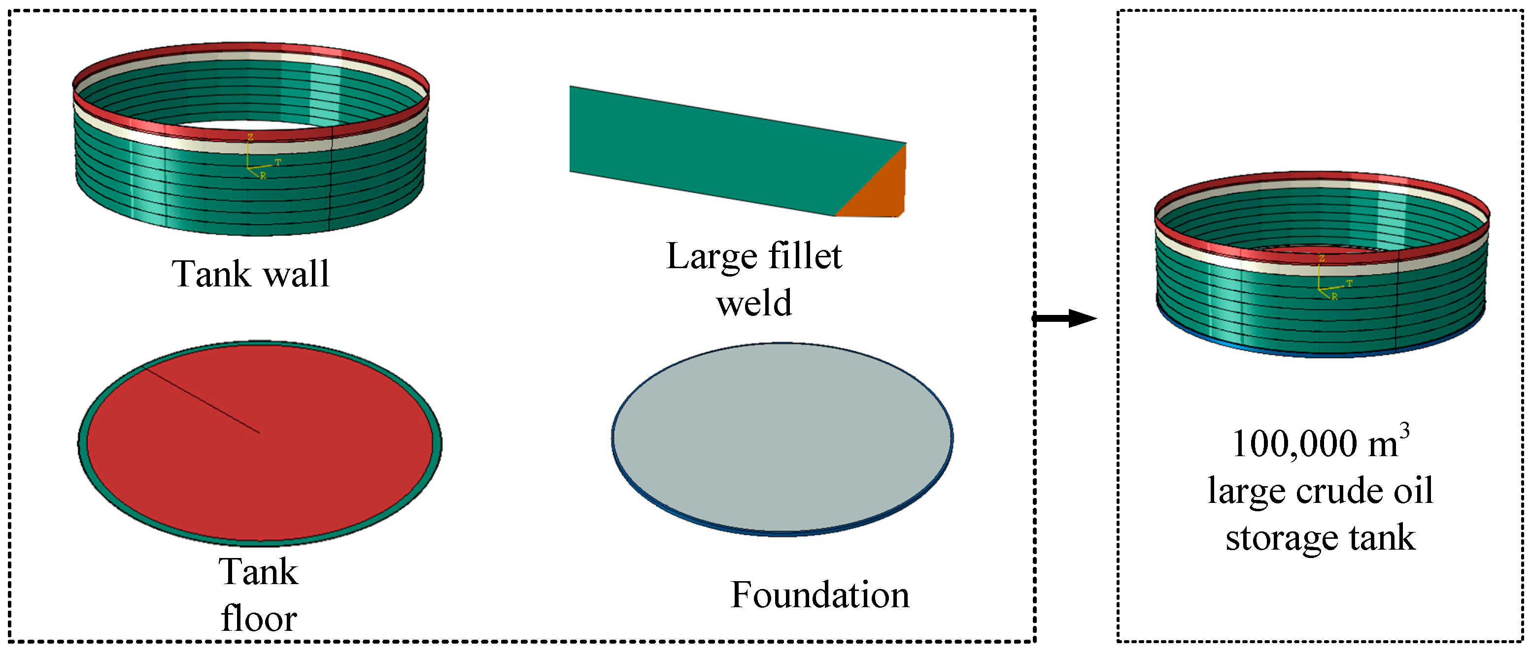
2.1. Geometric
2.2. Material
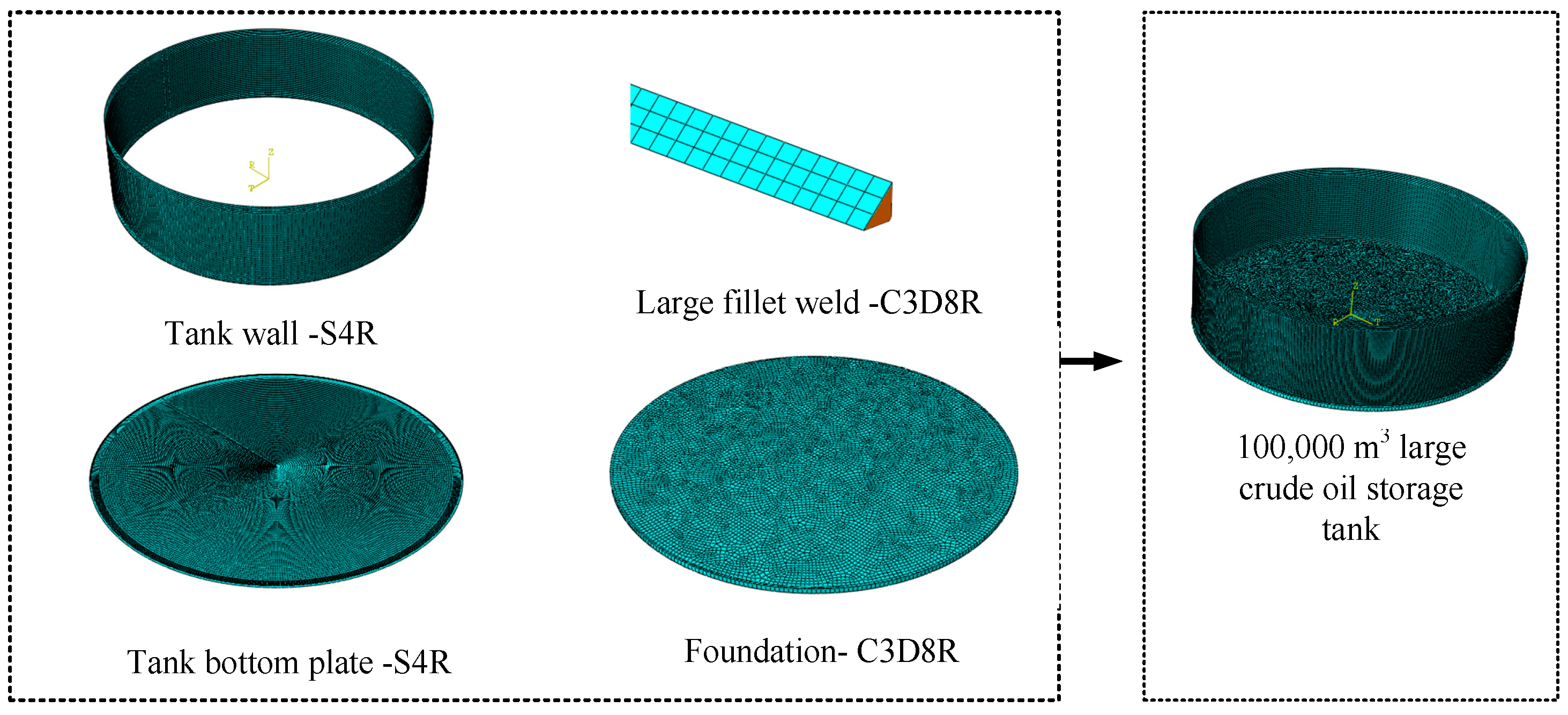
2.3. Mesh
2.4. Constraint Methods and Boundary Conditions
2.4.1. Model Constraint Methods
2.4.2. Model Boundary Conditions
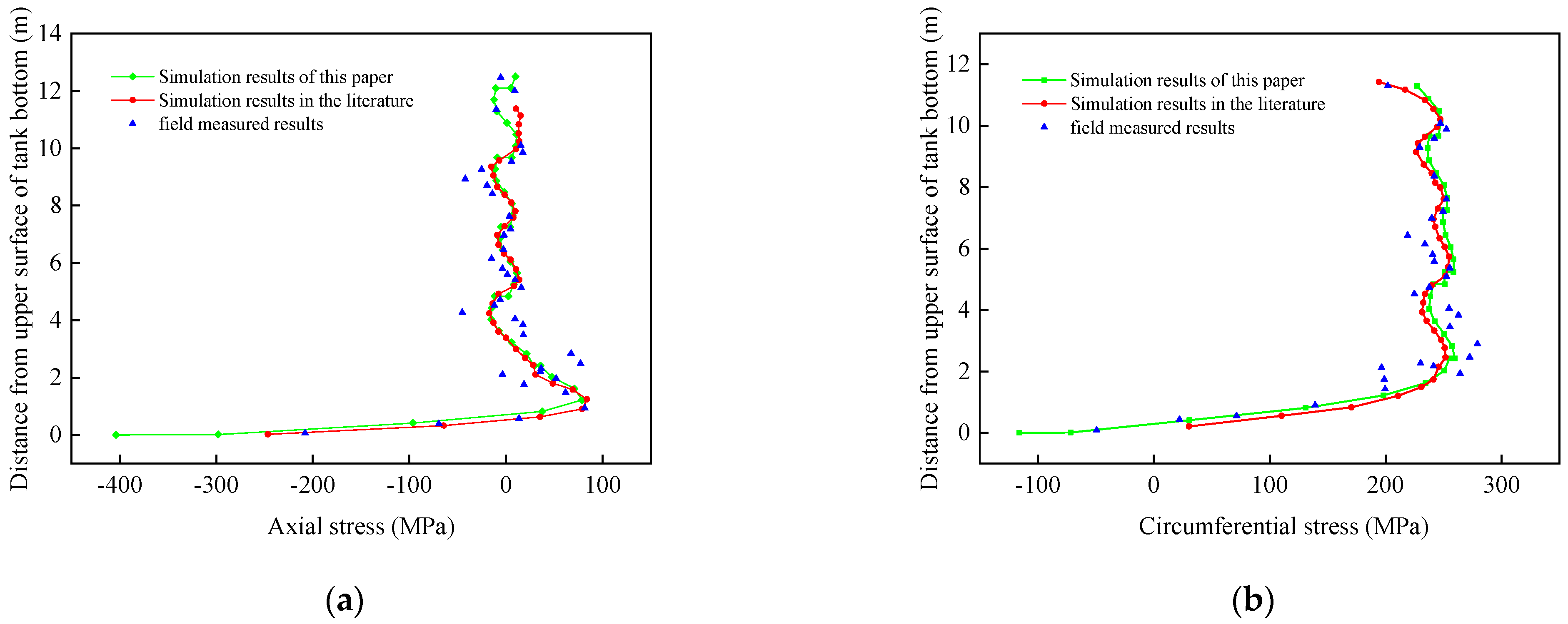
2.5. Verification of the Finite Element Model
3. Numerical Analysis of Large Crude Oil Storage Tanks Under Non-Uniform Ground Loads
3.1. Stress Response Analysis of Storage Tanks on Unsettled Foundations
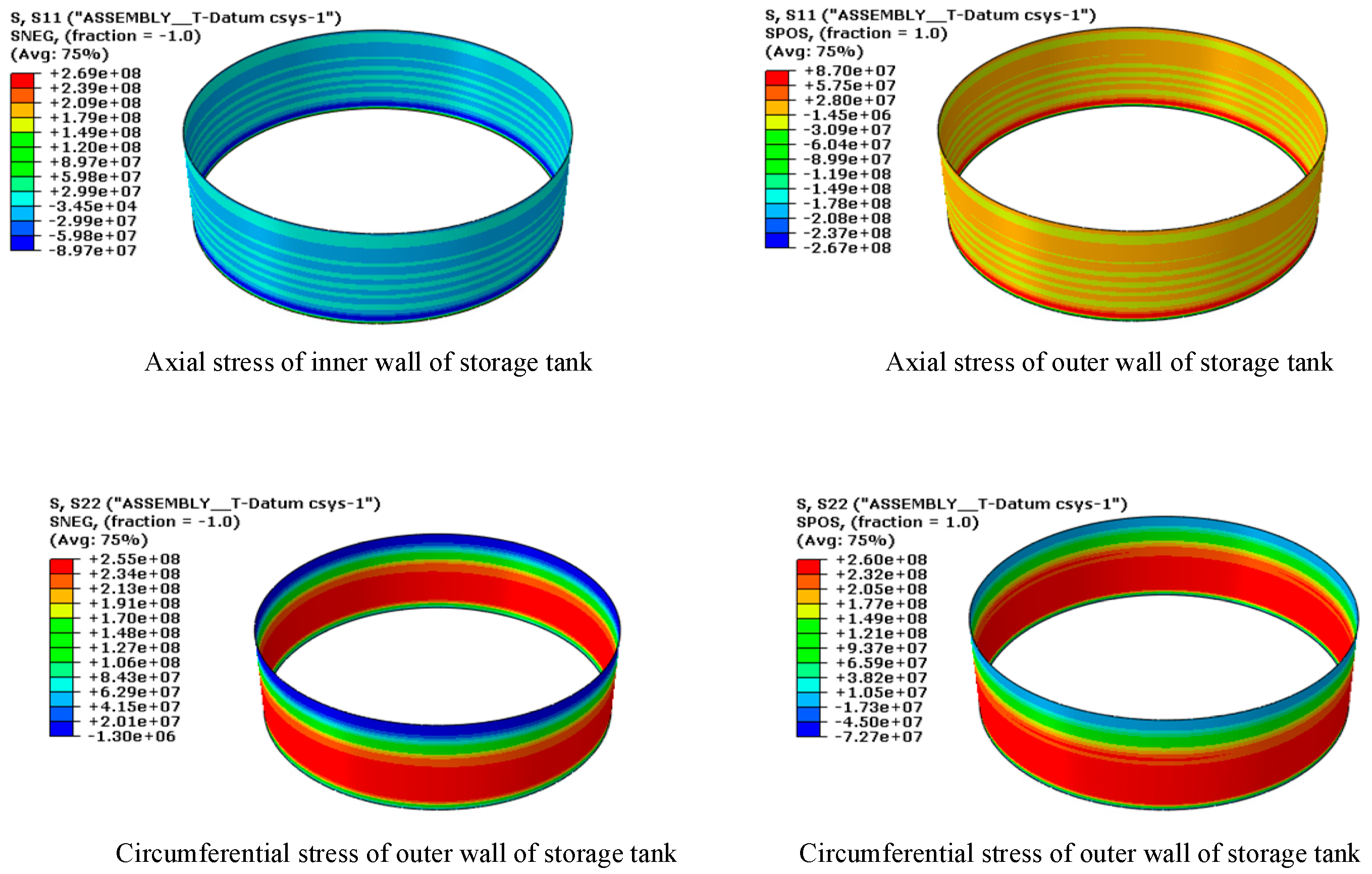
3.1.1. Stress Response of Tank Wall Panels
3.1.2. Stress Response of Tank Bottom Plates
3.2. Load Setting for the Tank Foundation Settlement
3.3. Analysis of Factors Influencing the Mechanical Response of a Storage Tank
3.3.1. Diameter-to-Thickness Ratio
3.3.2. Height-to-Diameter Ratio
3.3.3. Harmonic Number
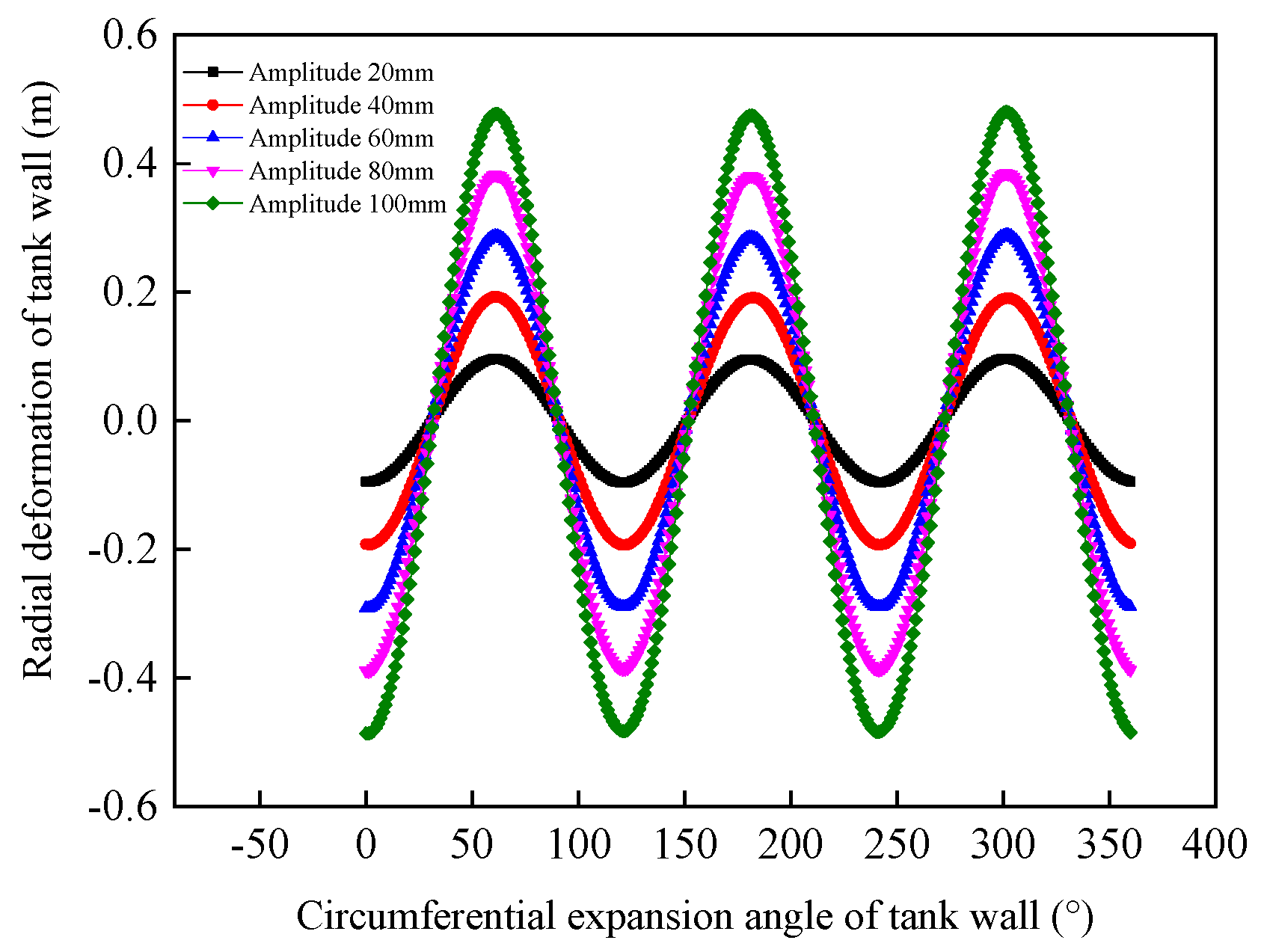
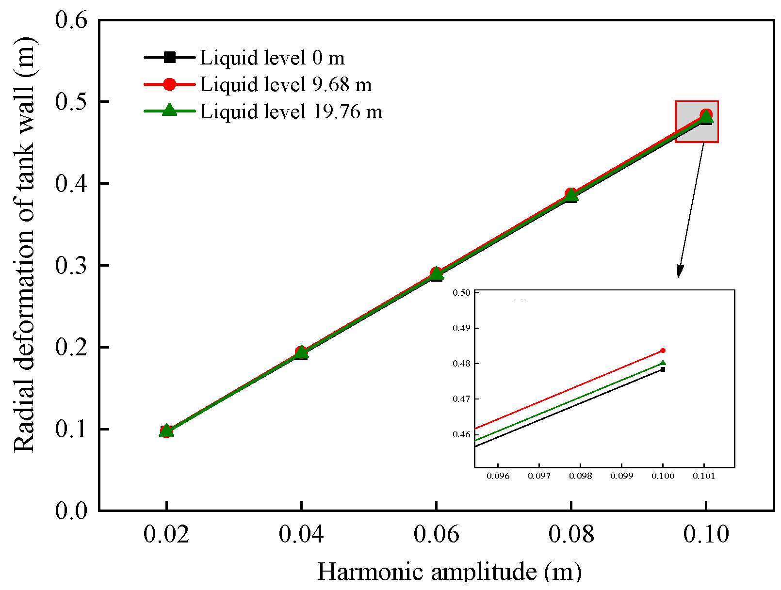
3.3.4. Harmonic Amplitude
4. Improved Evaluation Method for Storage Tanks Subject to Uneven Foundation Settlement
4.1. Influence of Foundation on the Nonlinear Response of Storage Tank Structures
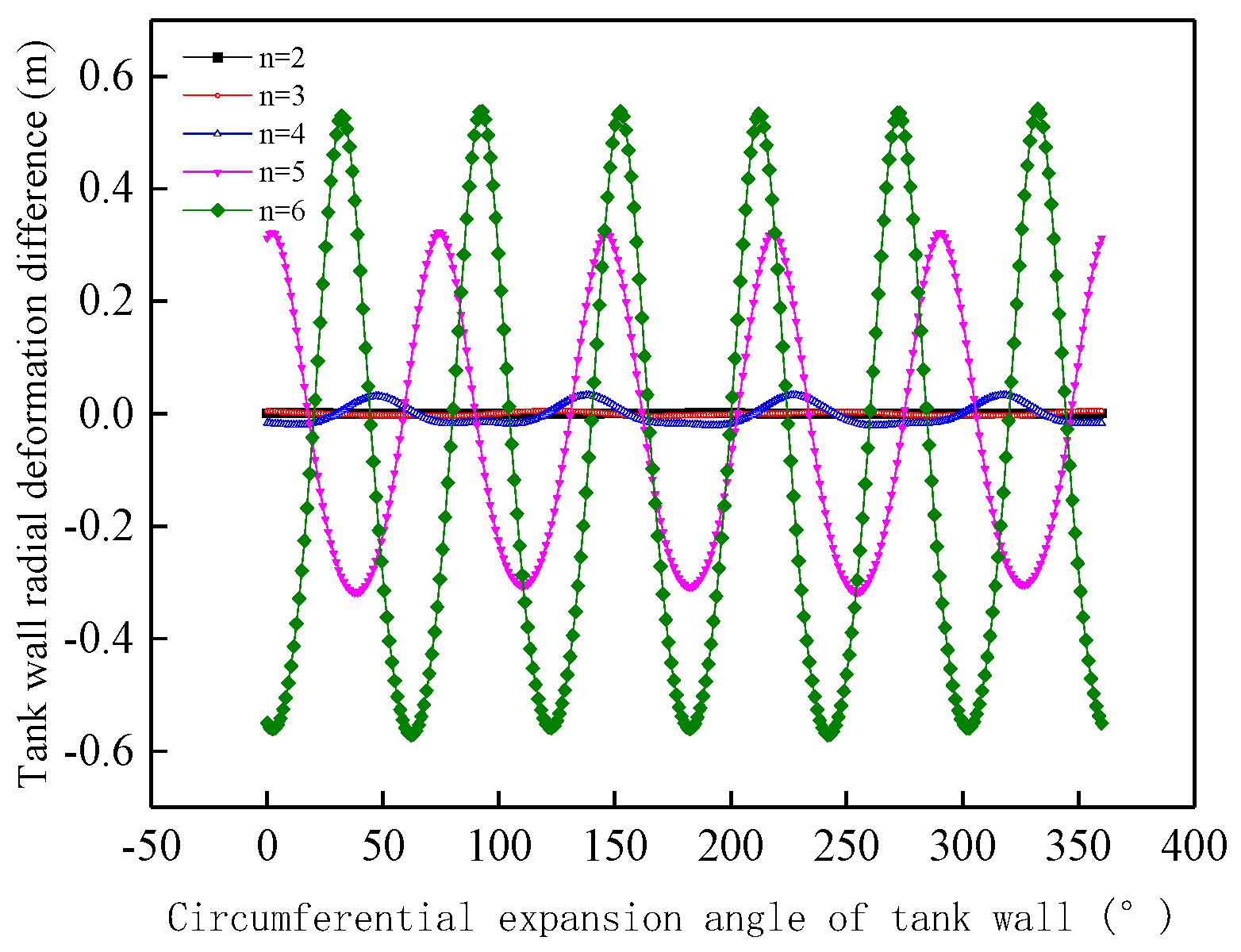
4.1.1. Influence of Harmonic Number on the Variability of Mechanical Response Results
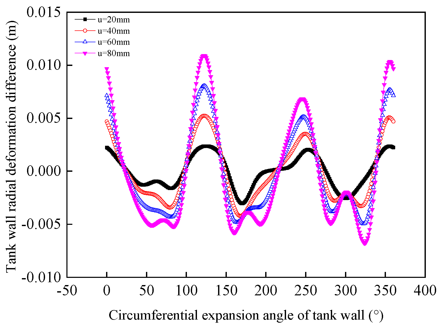
4.1.2. Influence of Harmonic Amplitude on the Variability of Mechanical Response Results
4.2. Research on Improvement Evaluation Method for Tank Deformation
5. Conclusions
- (1)
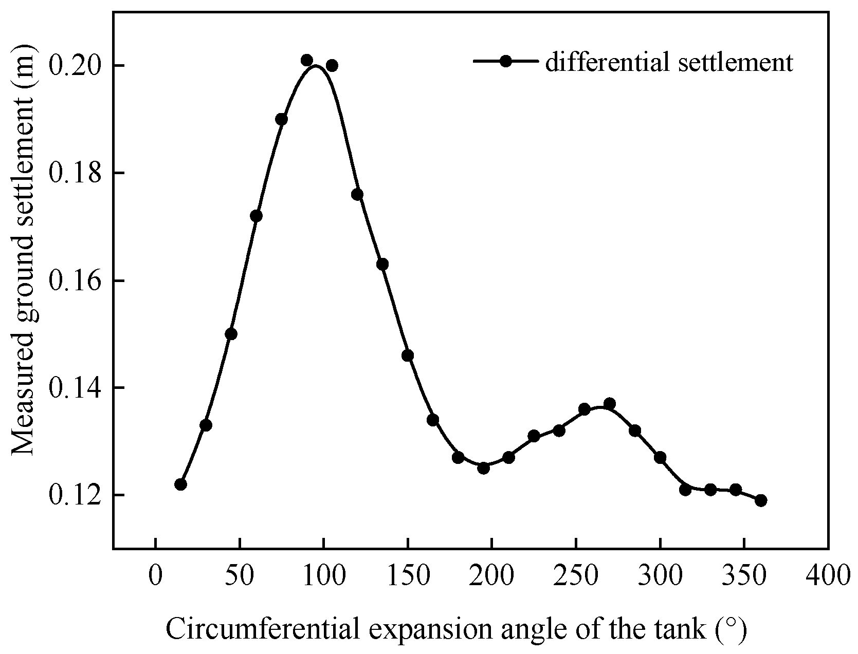
- By considering the coupling between foundation settlement and tank stress response under real service conditions, a mechanical simulation model for deformation analysis of large storage tanks subjected to uneven foundation settlement is established. The axial stress distribution in the tank wall, induced by hydraulic pressure and gravity, is calculated. The accuracy of the numerical simulation model is verified through a comparative analysis with field test data.
- (2)
- The radial deformation at the top of the tank wall is relatively less affected by the D/T and liquid level. It increases approximately linearly with the H/D and harmonic amplitude. Under low liquid level conditions, the radial deformation at the top of the tank wall increases with the harmonic number. Under high liquid level conditions, the radial deformation initially increases with harmonic number, but once the harmonic number reaches a point where the bottom plate separates from the foundation, the radial deformation decreases with further increases in harmonic number.
- (3)
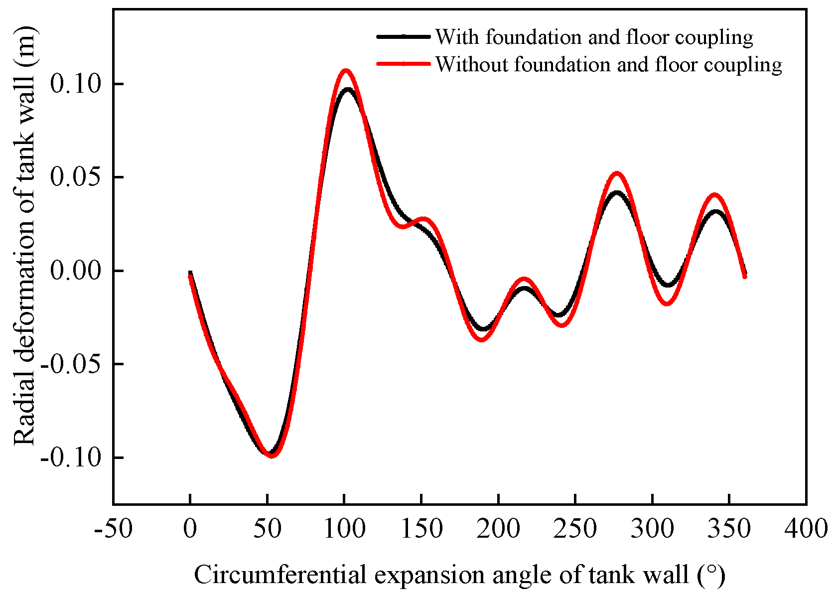
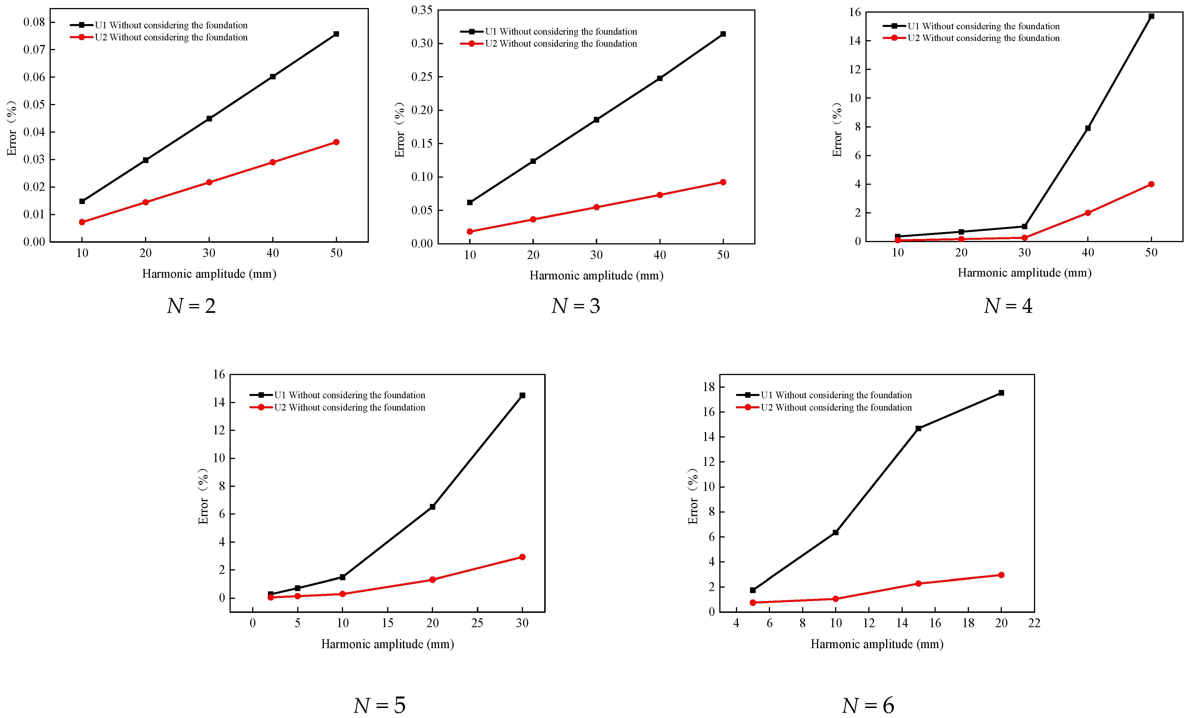
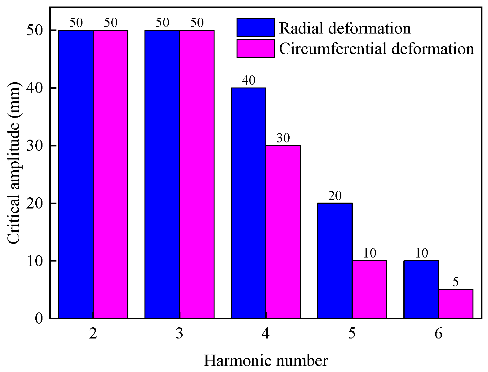
- The differences in the calculation results between tank numerical models that include or exclude foundation effects are analyzed, leading to an improved method for evaluating tank deformation. By quantitatively analyzing the influence of the harmonic number and amplitude on the mechanical response differences in the tank wall, this study provides estimates of the deformation errors resulting from neglecting foundation effects for harmonic numbers ranging from two to six and varying harmonic amplitudes for 100,000 m3 large storage tanks. Additionally, the critical range of harmonic amplitudes that meet specific accuracy requirements for these errors is given.
- (4)
- This article only studied the mechanical response analysis of a 100,000 m3 storage tank under foundation settlement, and further research can be conducted on the engineering application of different types of small crude oil storage tanks and improved evaluation methods.
Author Contributions
Funding
Data Availability Statement
Conflicts of Interest
References
- Pan, J.; Liang, S. A study on the buckling behavior of in-service large open-topped oil-storage tanks. Structures 2021, 29, 211–224. [Google Scholar] [CrossRef]
- Zhao, J.; Li, M.; Liu, S.; Dong, H. Heat transfer characteristics of oil receiving and delivering process in crude oil storage tanks. Case Stud. Therm. Eng. 2024, 61, 104994. [Google Scholar] [CrossRef]
- Ji, S.; Cheng, Q.; Sun, W.; Qi, Y.; Wang, S. Study on optimal operation conditions in the heating process of a crude oil single-disk floating roof tank: Insights from exergy transfer analysis method. Energy Rep. 2023, 9, 3131–3147. [Google Scholar] [CrossRef]
- Zhao, Y.; Lei, X.; Wang, Z.; Cao, Q. Buckling behavior of floating-roof steel tanks under measured differential settlement. Thin-Walled Struct. 2013, 69, 70–80. [Google Scholar] [CrossRef]
- Alphose, Z. Liquid-containment shells of revolution: A review of recent studies on strength, stability and dynamics. Thin-Walled Struct. 2015, 87, 102–114. [Google Scholar]
- Ozdemir, Z.; Souli, M.; Fahjan, Y. Application of nonlinear fluid–structure interaction methods to seismic analysis of anchored and unanchored tanks. Eng. Struct. 2010, 32, 409–423. [Google Scholar] [CrossRef]
- Konstantinos, B.; Spyros, A.K. Uplift mechanics of unanchored liquid storage tanks subjected to lateral earthquake loading. Thin-Walled Struct. 2021, 158, 107145. [Google Scholar]
- Hamid, N.; Hossein, S.; Tadeh, Z. Experimental investigation of geometrical and physical behaviors of thin-walled steel tanks subjected to local support settlement. Structures 2021, 34, 413–422. [Google Scholar]
- Yannis, K.C.; Panagiota, T.; Takis, G.; Amalia, G.; Jacob, C.; Stéphan, U. 3D Effective stress analyses of dynamic LNG tank performance on liquefiable soils improved with stone columns. Soil Dyn. Earthq. Eng. 2023, 174, 108170. [Google Scholar]
- Manik, M.; Sabarethinam, K. Fragility assessment of bottom plates in above ground storage tanks during flood events. J. Loss Prev. Process Ind. 2023, 282, 104579. [Google Scholar]
- Carl, B.; Jamie, E.P. Fragility and risk assessment of aboveground storage tanks subjected to concurrent surge, wave, and wind loads. Reliab. Eng. Syst. Saf. 2019, 191, 106571. [Google Scholar]
- Bell, R.; Iwakiri, S. comparison used in tank-failure study. J. Geotech. Eng. Div. ASCE 1980, 106, 153–169. [Google Scholar] [CrossRef]
- Clark, J. Survey of oil tank failure. Ann. L’Institute Belg. Pet. 1969, 6, 15–24. [Google Scholar]
- D’Orazio, T.; Duncan, J.; Bell, R. Distortion of steel tanks due to settlement of their walls. J. Geotech. Eng. Div. ASCE 1989, 115, 871–890. [Google Scholar] [CrossRef]
- Zhang, S.; Kang, C.; Zhang, P.; Luo, J.; Shao, Y.; Wu, G.; Deng, B. Failure analysis of local settlement induced Q345R bottom plate cracking of crude oil storage tank. Heliyon 2022, 8, e11952. [Google Scholar]
- Rajmund, L.; Eugeniusz, H. Failure of cylindrical steel storage tank due to foundation settlements. Eng. Fail. Anal. 2020, 115, 104628. [Google Scholar]
- Min, H.; Chen, G.; Yang, P.; Hu, K.; Zhou, L.; Men, L.; Zhao, J. Multi-hazard coupling vulnerability analysis for buckling failure of vertical storage tank: Floods and hurricanes. Process Saf. Environ. Prot. 2022, 161, 528–541. [Google Scholar]
- Li, Q.; Zhao, D.; Yin, j.; Li, Y.; Chi, P.; Han, Y.; Ansari, U.; Cheng, U. Sediment Instability Caused by Gas Production from Hydrate-bearing Sediment in Northern South China Sea by Horizontal Wellbore: Evolution and Mechanism. Nat. Resour. Res. 2023, 32, 1595–1620. [Google Scholar] [CrossRef]
- Jonaidi, M.; Mohamed, K. Harmonic settlement effects on uniform and tapered tank shells. Thin-Walled Struct. 1998, 3, 237–255. [Google Scholar] [CrossRef]
- Ahmed, S.; Ansourian, P. Wall thickness variation effect on tank’s shape behaviour under critical harmonic settlement. Alex. Eng. J. 2016, 55, 3205–3209. [Google Scholar]
- Sina, N.; Hossein, S. Experimental Investigation to local settlement of steel cylindrical tanks with constant and variable thickness. Eng. Fail. Anal. 2020, 118, 104916. [Google Scholar]
- Fan, H.; Chen, Z.; Shen, J.; Cheng, J.; Chen, D.; Jiao, P. Buckling of steel tanks under measured settlement based on Poisson curve prediction model. Thin-Walled Struct. 2016, 106, 284–293. [Google Scholar] [CrossRef]
- Chen, Z.; Fan, H.; Cheng, J.; Jiao, P.; Xu, F.; Zheng, C. Buckling of cylindrical shells with measured settlement under axial compression. Thin-Walled Struct. 2018, 123, 351–359. [Google Scholar] [CrossRef]
- Suranga, G.; Hoyoung, S.; William, D.L.; Priyantha, W.J. Analysis of edge-to-center settlement ratio for circular storage tank foundation on elastic soil. Comput. Geotech. 2018, 102, 136–147. [Google Scholar]
- Luis, A.G. Buckling of vertical oil storage steel tanks: Review of static buckling studies. Thin-Walled Struct. 2016, 103, 1–21. [Google Scholar]
- Cao, Q.; Zhao, Y. Buckling strength of cylindrical steel tanks under harmonic settlement. Thin-Walled Struct. 2010, 48, 391–400. [Google Scholar] [CrossRef]
- Gong, J.; Tao, J.; Zhao, J.; Zeng, S.; Jin, T. Buckling analysis of open top tanks subjected to harmonic settlement. Thin-Walled Struct. 2013, 63, 37–43. [Google Scholar] [CrossRef]
- Zhao, Y.; Cao, Q.; Xie, X. Floating roof steel tanks under harmonic settlement: FE parametric study and design criterion. J. Zhejiang Univ. 2006, 7, 398–406. [Google Scholar] [CrossRef]
- Gong, J.; Cui, W.; Zeng, S.; Jin, T. Buckling analysis of large scale oil tanks with a conical roof subjected to harmonic settlement. Thin-Walled Struct. 2012, 52, 143–148. [Google Scholar] [CrossRef]
- Harsh, B.; Sukru, G. Fitness-for-service of open-top storage tanks subjected to differential settlement. Eng. Struct. 2020, 225, 111277. [Google Scholar]
- Yang, Z.; Yin, L. Buckling of cylindrical open-topped steel tanks under wind load. Thin-Walled Struct. 2014, 79, 83–94. [Google Scholar]
- Shervin, M.; Alireza, M. 3D wind buckling analysis of steel silos with stepped walls. Thin-Walled Struct. 2019, 142, 236–261. [Google Scholar]
- Shi, L. A Study on Strength and Stability of Large Scale Crude Oil Storage Tanks. Ph.D. Thesis, China University of Petroleum, Beijing, China, 2016. [Google Scholar]
- Grget, G.; Ravnjak, K.; Szavits, A. Analysis of results of molasses tanks settlement testing. Soils Found. 2018, 58, 1260–1271. [Google Scholar] [CrossRef]


| Material | Yield Strength/MPa | Hardening Exponent | Power Hardening Exponent |
|---|---|---|---|
| 08MnNiVR | 490 | 0.84 | 15.76 |
| 16MnR | 345 | 1.19 | 10 |
| Q235-B | 235 | 1.75 | 8.67 |
| Operating Parameters | Harmonic Amplitude/mm | Harmonic Number | Height-to-Diameter Ratio | Diameter-to-Thickness Ratio | Liquid Level/m |
|---|---|---|---|---|---|
| Value | 40 | 3 | 0.5 | 500, 800, 1200, 1500, 1700, 2000 | 0, 9.68, 19.76 |
| Operating Parameters | Harmonic Amplitude/mm | Harmonic Number | Height-to-Diameter Ratio | Diameter-to-Thickness Ratio | Liquid Level/m |
|---|---|---|---|---|---|
| Value | 40 | 3 | 0.5, 0.8, 1.0, 1.5 | 2200 | 0, 9.68, 19.76 |
| Operating Parameters | Harmonic Amplitude/mm | Harmonic Number | Height-to-Diameter Ratio | Diameter-to-Thickness Ratio | Liquid Level/m |
|---|---|---|---|---|---|
| Value | 40 | 2, 3, 4, 5, 6 | 0.5 | 2200 | 0, 9.68, 19.76 |
| Operating Parameters | Harmonic Amplitude/mm | Harmonic Number | Height-to-Diameter Ratio | Diameter-to-Thickness Ratio | Liquid Level/m |
|---|---|---|---|---|---|
| Value | 20, 40, 60, 80, 100 | 3 | 0.5 | 2200 | 0, 9.68, 19.76 |
Disclaimer/Publisher’s Note: The statements, opinions and data contained in all publications are solely those of the individual author(s) and contributor(s) and not of MDPI and/or the editor(s). MDPI and/or the editor(s) disclaim responsibility for any injury to people or property resulting from any ideas, methods, instructions or products referred to in the content. |
© 2024 by the authors. Licensee MDPI, Basel, Switzerland. This article is an open access article distributed under the terms and conditions of the Creative Commons Attribution (CC BY) license (https://creativecommons.org/licenses/by/4.0/).
Share and Cite
Jiao, Y.; Wang, Y.; Li, J.; Liu, X. Finite Element Analysis and Improved Evaluation of Mechanical Response in Large Oil Storage Tanks Subjected to Non-Uniform Foundation Settlement. Processes 2024, 12, 2838. https://doi.org/10.3390/pr12122838
Jiao Y, Wang Y, Li J, Liu X. Finite Element Analysis and Improved Evaluation of Mechanical Response in Large Oil Storage Tanks Subjected to Non-Uniform Foundation Settlement. Processes. 2024; 12(12):2838. https://doi.org/10.3390/pr12122838
Chicago/Turabian StyleJiao, Yuanqi, Yanbing Wang, Jinzhou Li, and Xiaoben Liu. 2024. "Finite Element Analysis and Improved Evaluation of Mechanical Response in Large Oil Storage Tanks Subjected to Non-Uniform Foundation Settlement" Processes 12, no. 12: 2838. https://doi.org/10.3390/pr12122838
APA StyleJiao, Y., Wang, Y., Li, J., & Liu, X. (2024). Finite Element Analysis and Improved Evaluation of Mechanical Response in Large Oil Storage Tanks Subjected to Non-Uniform Foundation Settlement. Processes, 12(12), 2838. https://doi.org/10.3390/pr12122838