Article

Modeling and Analysis of Internal Leakage Characteristics of the Internal Curve Motor by a CFD-Based Method

1
College of Energy and Power Engineering, Lanzhou University of Technology, Lanzhou 730050, China
2
State Key Laboratory of Fluid Power and Mechatronic Systems, Zhejiang University, Hangzhou 310027, China
3
School of Intelligent Manufacturing Engineering, Chongqing University of Arts and Sciences, Chongqing 402160, China
4
School of Mechanical Engineering, Liaoning Electromechanical Vocational and Technical College, Dandong 118009, China
*
Authors to whom correspondence should be addressed.
Processes 2024, 12(12), 2835; https://doi.org/10.3390/pr12122835
Submission received: 25 October 2024 / Revised: 3 December 2024 / Accepted: 9 December 2024 / Published: 11 December 2024
(This article belongs to the Section Process Control and Monitoring)

Abstract

:
Internal curve motors (ICMs) are used in construction and port machinery owing to their low speed and strong torque. The internal leakage of an ICM has a direct impact on its working performance; however, research on the internal leakage of ICMs is unclear. A method, based on the Computational Fluid Dynamics (CFD) transient simulation of an ICM, for obtaining the transient pressure in the plunger chamber and combining the mathematical model of internal leakage is calculated, and the internal leakage is proposed. We one-factor analyzed the internal leakage of the ICM and the effect of the valve pair and plunger pair leakage, and conducted multifactor analysis on the effect of the interaction between those two factors on the internal leakage of the ICM. The results show that the internal leakage mechanisms affecting the ICM were, in descending order of impact, the inlet pressure, oil temperature, and rotational speed, and a significant interaction existed between the inlet pressure and oil temperature, whereas the influence of rotational speed was not significant.

1. Introduction

The rapid advancement of hydraulic technology has driven the development of digital and intelligent hydraulics, which are a key focus of the industry. High-performance hydraulic pumps and motors are fundamental to this development [1,2,3]. ICMs have high working pressure, powerful low-speed stability, high output torque, and other characteristics, and have been widely used in marine machinery, construction machinery, chemical production, port machinery, and other industries [4,5,6]. However, internal leakage of the ICM at low speeds can cause problems such as creeping and noise, thereby reducing the output power and usability. Internal leakage is caused by the internal motion components of the ICM, which include the friction pair clearance (valve pair, plunger pair, and roller pair) [7]. The clearance between the friction parts is filled with oil, which is the main channel of internal leakage of an ICM. The leakage of an ICM is affected by the size of the leakage clearance, the motion state between the friction pair, the pressure difference between the two ends of the clearance, and the characteristics of the working medium [8,9]. Conversely, analyzing internal leakage can provide valuable insights into the characteristics of the motor’s friction pairs, ultimately contributing to improved hydraulic pump/motor performance.
Research on internal leakage in motors primarily consists of theoretical calculations and experimental test methods [10]. The theoretical calculation method was used to analyze the characteristics of the oil film in the leakage clearance taking the hydrostatic empirical formula as the research basis, considering the hydrodynamic effect of oil film lubrication, expressing the characteristics of the oil film through the Reynolds equation, numerically solving the thickness of the oil film, and then calculating the amount of internal leakage of the ICM. However, ICM working conditions are complex, the working environment is harsh, the working pressure changes in real time, and the boundary conditions of the model calculation change. Therefore, the theoretical calculation method cannot accurately calculate the internal leakage of the ICM. The testing method typically involves measuring the ICM input and output oil flow on a test platform to calculate leakage or directly measure leakage at the discharge port. While straightforward, these tests are crucial for validating the theoretical leakage calculations. However, the direct measurement of ICM leakage has the disadvantage of requiring considerable initial expenditure and only one sample for experimentation. As a result, combining theoretical calculations and experimental testing improves the accuracy of ICM internal leakage calculations, while also reducing the difficulty associated with theoretical model estimates.
The end-face distribution flow hydraulic pump/motor research theory is similar in hydraulics. The valve plate, as a hydraulic pump/motor pressure adaptation mechanism [11,12], is an important component of the hydraulic pump/motor. Axial piston pump (APP) employ a fixed valve plate attached to the casing and cannot dynamically alter the clearance of the valve pair. However, the ICM has a floating end-face distribution oil structure, and the valve plate floats between the cylinder and the shell; through the pressure in the plunger chamber, the floating valve plate can adjust and compensate for the sealing clearance and lubricating performance of the valve plate. The floating valve plate oil film maintains complete lubrication, but the valve pair lubricating oil film’s characteristics are different from the fixed valve plate oil film lubrication’s characteristics. A smaller range takes place between the valve pair clearance and the lubricating oil film, meaning that the “Surplus Pressing Force” method must be used in the design. Owing to the similarities in design and motion between ICM plunger pairs and those in the APP, the same leakage estimation methods can be applied to ICM plunger pairs. The lubricating film state of the roller friction pair of the ICM is divided into two stages: when the pressure in the plunger chamber is in the high-pressure area, the oil film of the roller friction pair is in the boundary lubrication, the thickness of the oil film is extremely thin, and the leakage of the roller pair is very small; when the pressure in the plunger chamber is in the low-pressure area and is less than 0.8 MPa, the leakage of the roller pair is small, and the leakage of the roller pair is limited compared to the leakage of the valve pair and the plunger pairs [1] and is negligible [13,14,15,16]. Consequently, only the leakage of the valve plate and plunger pair was investigated for the internal leakage in the ICM.
Transient research on hydraulic pumps/motors is the focal point for evaluating their operational performance. Wu et al. used CFD software to investigate the flow field characteristics of an axial plunger motor, and transient analyses were performed on various damping grooves on the end face of the valve plate, as well as a new type of damping groove, which revealed the pressure and flow fluctuations of the axial plunger motor and the cavitation phenomenon under different structural parameters [17]. Li et al. studied the flow field characteristics of the ICM, as well as the effects of oil film thickness, inlet pressure, motor speed, and oil temperature on valve plate leakage. The reliability of the CFD model was confirmed by comparing the simulation results with experimental data, and the leakage of the ICM was investigated [18].
Meanwhile, other researchers, using an APP as their research subject, derived equations for plunger pump clearance leakage and validated them numerically. They subsequently developed a dynamic characteristic model for the plunger pump, deriving equations for the instantaneous plunger chamber pressure and instantaneous clearance leakage [19,20]. The leakage of the inner and outer sealing bands of the valve plate of an APP at different pressures has been investigated [21,22]. A leakage-based fault-detection method for a variable pump-fixed displacement motor hydrostatic transmission system has been proposed, a mathematical simulation model of plunger pump leakage and a thermoelastic flow dynamics model of the APP have been established, and the oil film characteristics, friction, and leakage of the friction pair of the APP under normal working conditions have been determined and investigated [23,24]. The leakage factors of the APP have been investigated, and the main leakage channels, which involve the valve, plunger, and sliding shoe pairs, have been elaborated. It has been proposed that the internal flow in each friction pair can be equated to the clearance flow of different geometries, and a mathematical model of the internal leakage of the APP has been deduced [25,26]. Neeraj et al. investigated the relationship between the outlet flow rate and leakage flow rate of an APP, verified the thermodynamic characteristics of the plunger pump, and investigated variations in the inlet, outlet, leakage flow, casing, and tank temperatures [27]. Sun et al. developed an indirect measurement method for double tandem APPs based on leakage flow estimation [28]. V. D. Phan et al. proposed a novel fault-tolerant controller for a double-rod electro-hydraulic actuator for motion control systems with system disturbances and internal leakage faults [29]. Separately, Ma et al. researched seawater APPs and investigated their leakage mechanisms using a deep-sea environmental test bench for plunger pumps and a combination of experimental and theoretical methods [30].
As mentioned above, APPs, valve pairs, and plunger pairs have been the subject of numerous research projects. However, there are few studies on the leakage of the ICM valve pair and plunger pair, or on the relationship between the factors influencing ICM leakage and the degree of their influence. Furthermore, few studies have analyzed the transient internal fluid domain to determine the pressure characteristics of the internal flow field of the ICM. Therefore, this study proposes a method to calculate the internal leakage of the ICM as well as the leakage of the valve pair and the plunger pairs using a combination of CFD simulations and mathematical modeling to analyze the relationship between them. First, a full-fluid domain simulation model of the ICM was created, and transient flow-field simulations were performed using appropriate parameter settings. Second, the plunger chamber transient pressure value coupled with a mathematical model for leakage is calculated as the internal leakage of the ICM and the leakage of the valve pair and plunger pair. Finally, Design-Expert 13 software was used to perform a multifactor working condition analysis of the simulated experimental model to clarify the interactive effects of the two factors on internal leakage in the ICM. This is crucial for predicting ICM leakage and optimizing the design parameters.

2. Experiments

2.1. Experimental Principle

The main components of the internal leakage of the experimental platform were the hydraulic pump, hydraulic motor, and solenoid valve. Internal leakage is affected by the working pressure of the system, the operating speed, and the temperature of the oil. Moreover, internal leakage affects the control sensitivity and stability of the experimental platform; therefore, a reasonable design of the experimental platform is of great significance in improving the test’s authenticity and accuracy. In this study, only the internal leakage of the ICM was tested, and the mathematical model was refined by comparing the calculated and experimental results, validating the accuracy and reliability of the combined method using the instantaneous plunger chamber pressure and internal leakage mathematical model. Figure 1 shows a schematic diagram of the test bench, which uses two identical types and specifications of ICM: one as the test motor and the other as the load pump. These were connected via a common shaft to a test motor driving the load pump. A bridge hydraulic circuit ensures that the load pump draws oil from the low-pressure port. A three-position, three-way valve controlled the tank connection based on the pressure difference across the test motor. A flow control valve regulates the load pump flow, and the proportional relief valve limits the load pump outlet pressure. The test equipment comprised a ZH07 torque-speed sensor (Beijing AVIC Science and Electricity, Beijing, China), PT5401 pressure sensor (Shanghai IFM Electronics, Shanghai, China), GF6F1P1 gear flow meter (Huzhou Instrumentation, Huzhou, China), and CRM-HA50-50 internal curve hydraulic motor (Ningbo Stauffer Hydraulics Transmission, Ningbo, China). Its physical appearance is shown in Figure 2.

2.2. Experimental Method

Tests were conducted on the test bench by adjusting the speed-regulating valve in the bridge hydraulic circuit to control the load pump speed and the proportional relief valve pressure to control the load pump outlet pressure. By setting various operating parameters, internal leakage was measured at different pressures, speeds, and oil temperatures. The tests were divided into three tasks. The first task set the test motor speed to 1 RPM and the oil temperature to 40 °C; the purpose of the test was to identify the internal leakage amount of the ICM under different inlet pressures. The test bench was operated continuously for 2 min, six different operating pressures were applied to the test motor, and the resulting internal leakage flow rates were recorded to determine the relationship between the inlet pressure and leakage. In the second task, the test motor working pressure was set to 24 MPa and the oil temperature was set to 40 °C, the purpose of which was to identify the internal leakage amount of the ICM under different rotational speeds. The test bench was operated continuously for 2 min, and six different rotational speeds were tested, recording the internal leakage flow rate at each speed to determine the relationship between the rotational speed and leakage. In the third task, the test motor pressure was set to 24 MPa, and the speed was set to 1 RPM to identify the amount of internal leakage of the ICM under different rotational speeds. The test bench was operated continuously for 2 min, and seven different oil temperatures were tested, recording the internal leakage flow rate at each temperature to determine the relationship between the oil temperature and leakage.

3. Numerical Methods

3.1. ICM Structural Characteristics

As shown in Figure 3, the structure of the ICM consists of a housing, rotor, valve plate, plungers, rollers, and other components, and high-pressure oil enters the rotor plunger chambers via flow channels. The valve plate distributes the pressure oil, and the resulting hydraulic pressure on the plungers drives 16 plunger assemblies (plunger and roller) along the stator guide rails inside the housing. These rails consist of ten identical stator curves that are evenly spaced within the housing. Hydraulic pressure maintains the contact between the plunger assemblies and stator rails, generating tangential and radial forces. The tangential force produces torque by rotating the ICM.

3.2. Computational Domain and Mesh Grid

As shown in Figure 4, the fluid computational domain of the ICM was divided into three sections: a lower valve plate domain (containing 20 inlet/outlet and 20 balancing chamber fluid domains), a middle valve pair domain (meshed in four longitudinal layers), and an upper rotating domain (containing 16 plunger chamber fluid domains and connecting oil channels). A structured mesh was used for the ICM fluid domain by employing moving and sliding mesh techniques. The motion of the piston domain mesh was controlled by a user-defined function (UDF) in Fluent, which achieves both radial and circular motions of the plunger domain around the axis of rotation.

3.3. Numerical Simulation

3.3.1. CFD Solver

ANSYS Fluent double-precision numerical computing was employed, and the solver employed the pressure interpolation approach and transient computation strategy to carry out the simulation using the pressure-velocity coupling scheme and the PISO interpolation format, with the spatial discretization in the QUICK format the pressure discretization in the PRESTO! format, momentum, kinetic energy, and turbulence intensity in a second-order discretization format, and time discretization in a second-order implicit format. In addition, the UDF was employed in the fluid domain to calculate the velocity and displacement of the plunger domain grid.

3.3.2. Model Simulation

The flow field of the ICM was simulated to monitor the transient pressure in each plunger chamber. As shown in Figure 5, pressure changes within the chambers follow the operating rules, the simulation results converge, and the mesh remains undistorted, suggesting that transient simulation of the ICM’s full flow field is possible.
In Figure 5, the simulation time is 0 s for the initial state of the flow field of the ICM, the eight plunger chambers were connected to the high-pressure oil, the low-pressure oil was connected to eight plunger chambers, and the plungers were positioned to correspond to the distribution angle of the stator ring curve. At 0.3 s, the simulation shows six piston chambers connected to high-pressure oil and eight to low-pressure oil, with two chambers experiencing a pressure transition. At 0.5 s, further changes in piston chamber pressure and position occur. The transient pressure data obtained through the simulation support the calculation of the ICM internal leakage.

3.4. Model Validation

3.4.1. Grid Independence Validation

The accuracy of CFD simulation results for the model mesh grid density is crucial [31]. Four mesh density models were used in this study: 300 K (coarse), 600 K (medium), 1200 K (fine), and 2400 K (ultrafine). This method allowed for the evaluation of the influence of mesh density on the simulation results. As shown in Figure 6, as simulation results stabilize as mesh density increases, the difference in results between the 600 K, 1200 K, and 2400 K element meshes is less than 5%, indicating that the results are convergent, reliable, and capable of meeting the grid independence conditions; the full fluid domain transient simulation of the ICM is dependable. Therefore, the 600 K mesh density was selected as the model for the full fluid domain simulation of the ICM to reduce computing costs.

3.4.2. Calculation Time Step Independence Verification

In this study, the flow domain simulation adopted a moving grid layer, reconstructed, and adopted the grid slip method. However, the grid collapses, reconstructs, deforms, and undergoes other institutional changes in the course of movement. The simulation time step influences grid movement and deformation, which can affect the accuracy of the simulation results [31]. In this study, four time steps (0.0002 s, 0.0001 s, 0.00005 s, and 0.00001 s) were calculated, and their effects on the plunger chamber pressure are shown in Figure 7. The minimum simulation time step was determined by the size of the mesh grid and the angular velocity of the ICM, and the simulation results did not converge when the time step was larger than 0.0002 s. However, when using time steps of 0.0002 s and smaller, the pressure in the plunger chamber is the same and the simulation result will no longer be affected by the computational time step, indicating time-step independence and that the ICM fluid domain transient simulation is reliable. The computational step time for the transient simulation of the ICM fluid domain was set to 0.0002 s to reduce the calculation time.

3.5. Leakage Modeling of the ICM

The internal leakage in the ICM is primarily caused by the valve pair and plunger pairs; key factors influencing leakage in these friction pairs include the sealing area between sliding surfaces, the operating pressure, and the relative sliding speed of the pairs.

3.5.1. Leakage Modeling of the Valve Pair

The parallel plane clearance between the cylinder body and valve plate is small, and it is usually assumed that the oil film of the valve pair is laminar and incompressible, and that the pressure remains constant in the vertical oil film direction [20,32,33]. The valve plates inside and outside the sealing band produce an annular clearance, and the sealing band leakage is affected by the cylinder angle and pressure in the plunger chamber [34]. The studied ICM model has 16 piston chambers; each plunger chamber’s pressure will be different from the motor rotation, and the pressure angle and pressure range will be different. The calculation method has already been described in the literature and has not been repeated [11,35]. According to the hydraulic component clearance, the flow characteristics can be deduced from the ring seal clearance leakage formula, which is known as the annular seal clearance leakage, as follows:
Q P d = α h 3 6 μ C e P s ln R m / R n + π D v h 2   = α h 3 6 μ C e 1 ln R 1 / R 2 + 1 ln R 3 / R 4 P s 1 + P s 2 + + P s 15 + P s 16   + w h 4 R 1 2 R 2 2 + R 3 2 R 4 2
where Q P d is the leakage of the valve pair, α is the pressure angle, h is the oil film thickness, μ is the dynamic viscosity of the fluid, C e is the correction factor, P s is the pressure in the plunger chamber, R m is the radius of the outer sealing band, R n is the radius of the inner sealing band, D is the diameter of the center circle of the position of the distribution holes, and v is the relative sliding speed.

3.5.2. Plunger Pairs Leakage Modeling

The oil film between the valve and plunger pairs was assumed to be under the same conditions. The plunge radial movement during ICM rotation causes its sealing band length and radial velocity to change with cylinder angle [36]. The eccentricity of the plunger is negligible because the oil film pressure between the plunger pairs has a corrective effect on plunger movement [37,38]. The instantaneous leakage flow equation for the ICM plunger is as follows:
Q S d = π d h 3 12 μ l c P s + π d v i h 2   = π d h 3 12 μ l 1 P s 1 + π d h 3 12 μ l 2 P s 2 + + π d h 3 12 μ l 15 P s 15 + π d h 3 12 μ l 16 P s 16   + π d h 2 v 1 + v 2 + + v 15 + v 16
where Q Sd is the leakage of the plunger pair, l i is the length of the plunger sealing band, v i is the radial velocity of the plunger, and d is the diameter of the plunger.

3.5.3. Internal Leakage of the ICM

Therefore, the instantaneous internal leakage of the ICM is as follows:
Q = Q Pd + Q Sd = Q PV + Q P L
where Q P V is the differential pressure leakage of the valve pair and Q P L is the shear leakage of the plunger pair, as shown in Equation (4):
Q P V = h 3 P s i 6 μ 1 C e 1 ln R 1 / R 2 + 1 ln R 3 / R 4 + π D 2 l i Q P L = h w 4 R 1 2 R 2 2 + R 3 2 R 4 2 + π D 2 v i
Substituting the data in Table 1 and the instantaneous pressure in the plunger chamber into Equations (3) and (4) yields the amount of internal leakage of the ICM, the leakage of the valve pair, and the plunger pairs.

4. Results and Discussions

In this study, we first analyzed the effect of one-factor change on the internal leakage of ICM by one-factor analysis, assuming that other factors remain unchanged, and determined the order and degree of factors affecting the internal leakage. We then investigated the effect of two-factor changes on the internal leakage of ICM by multifactor analysis, revealing the interactions between the factors. However, the multifactor analysis method uses analysis of variance (ANOVA), which requires multiple tests and collection of relevant data and is computationally intensive and complex; however, it provides more comprehensive and detailed results than the one-factor analysis.

4.1. Analysis of One-Factor Working Conditions Simulation Test

To investigate the ICM’s internal leakage, a one-factor simulation study was conducted and compared with the experimental data. The established ICM leakage model identifies the oil film thickness, input pressure, rotational speed, and oil temperature as the key influencing factors. It is important to note that the ICM uses a floating valve plate with an internal pressure feedback mechanism because the floating valve plate design ensures a consistently fully lubricated valve pair with minimal oil film thickness variation. A one-factor working conditions simulation study focusing on inlet pressure, rotational speed, oil temperature, and internal leakage was calculated using the instantaneous pressure of the plunge chamber and the mathematical modeling of the ICM leakage and analyzed the influence of a one-factor on ICM internal leakage under various operating conditions.

4.1.1. The Effect of Inlet Pressure on the Internal Leakage of the ICM

As shown in Figure 8, when the ICM speed was 1 RPM and the oil temperature was 40 °C, with six different inlet pressures, the internal leakage of the ICM increased with increasing pressure and the flow rate pulsation also increased, but the amplitude of the fluctuation remained relatively flat. As shown in Figure 8a, when the inlet pressure was 4 MPa, the ICM’s calculated leakage was 0.1076 L/min and the measured leakage was 0.1103 L/min. The calculated leakage was slightly larger than the measured leakage, with an error of less than 2.4%. When the inlet pressure was 24 MPa, the ICM’s calculated leakage was 1.4957 L/min, the measured leakage was 1.5258 L/min, the error was less than 1.9%, the error between the calculated leakage and the measured leakage of the ICM under other inlet pressures was less than 3%, and the linear growth trends of the calculated and simulated values were the same. As shown in Figure 8b, when the inlet pressure was 4 MPa, the leakage of the valve pair was 0.0779 L/min, whereas the leakage of the plunger pairs was 0.0324 L/min. When the inlet pressure was 24 MPa, the leakage of the valve pair was 1.3615 L/min, whereas that of the plunger pairs was 0.1642 L/min. The leakage of the valve pair was far greater than that of the plunger pairs, and both the flow rates increased when the pressure increased. As shown in Figure 8c, the leakage of the valve pair with the minimum value is 70.6% and with the maximum value is 89.2%; the overall trend of the percentage of leakage is increasing rapidly; the leakage of plunger pairs has the minimum value of 10.8% and the maximum value of 29.4%, and the overall trend of the percentage of leakage decreases. When the pressure is increased, the proportion of valve pair leakage in the internal leakage of the ICM increases, whereas the proportion of plunger pair leakage in the internal leakage of the ICM decreases. In summary, the inlet pressure significantly affects the internal leakage of the ICM, increasing the leakage flow in both the valve and piston pairs with an increase in the inlet pressure.

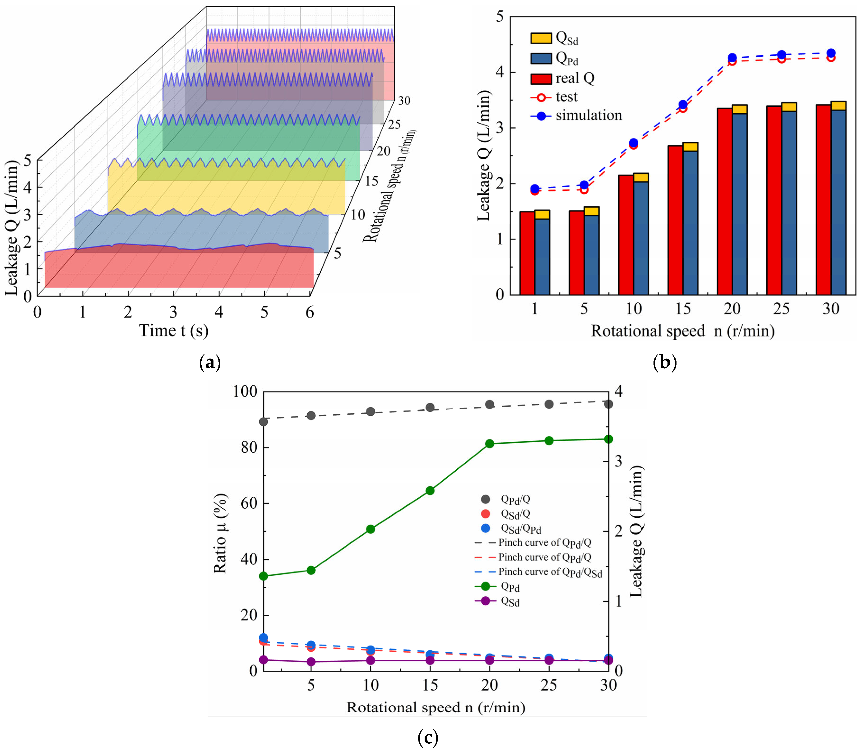
4.1.2. The Effect of Rotational Speed on the Internal Leakage of the ICM

As shown in Figure 9, when the ICM of the inlet pressure was 24 MPa and the oil temperature was 40 °C, with six different rotational speeds, the internal leakage of the ICM increased with rotational speed, and higher rotational speeds also resulted in increased amplitude and frequency of flow pulsation. As shown in Figure 9a, the internal leakage of the ICM can be separated into three stages as the rotational speed increases: a smaller leakage stage occurs at 1–2 r/min; a linear leakage stage occurs at 5–20 r/min; and a constant leakage stage occurs at 20–30 r/min. As shown in Figure 9b, the actual leakage of the ICM is slightly smaller than the calculated value, which is due to the simulation value of the more perfect boundary conditions. However, the error between the measured and calculated values was less than 5%, and the trends were similar. When the rotational speed was 1 r/min, the leakage of the valve pair was 1.3615 L/min, and that of the plunger pairs was 0.1642 L/min. When the rotational speed was 30 r/min, the leakage of the valve pair was 3.3222 L/min, and that of the plunger pairs was 0.1548 L/min. The leakage of the valve pair increased with an increase in rotational speed. When the rotational speed was 20 r/min, the leakage of the plunger pairs remained largely unchanged with an increase in rotational speed, and the trend of the change remained horizontal. As shown in Figure 9c, the percentage of leakage of the valve pair in the ICM leakage is at a minimum of 89.2% and a maximum of 95.5%; the overall trend is gradually increasing, whereas the percentage of leakage of the plunger pairs is 4.5% at minimum and 10.8% at maximum, and the general trend slowly decreases. Similarly to the trend of plunger pair leakage as a percentage of leakage in the ICM, the ratio of plunger pair leakage to valve pair leakage exhibited a declining tendency. Consequently, the impact of the ICM rotational speed on plunger pair leakage diminishes as the rotating speed increases, and the final leakage remains constant, but the leakage flow pulsation increases. The leakage of the valve pair remains unchanged when the rotational speed reaches 20 r/min.

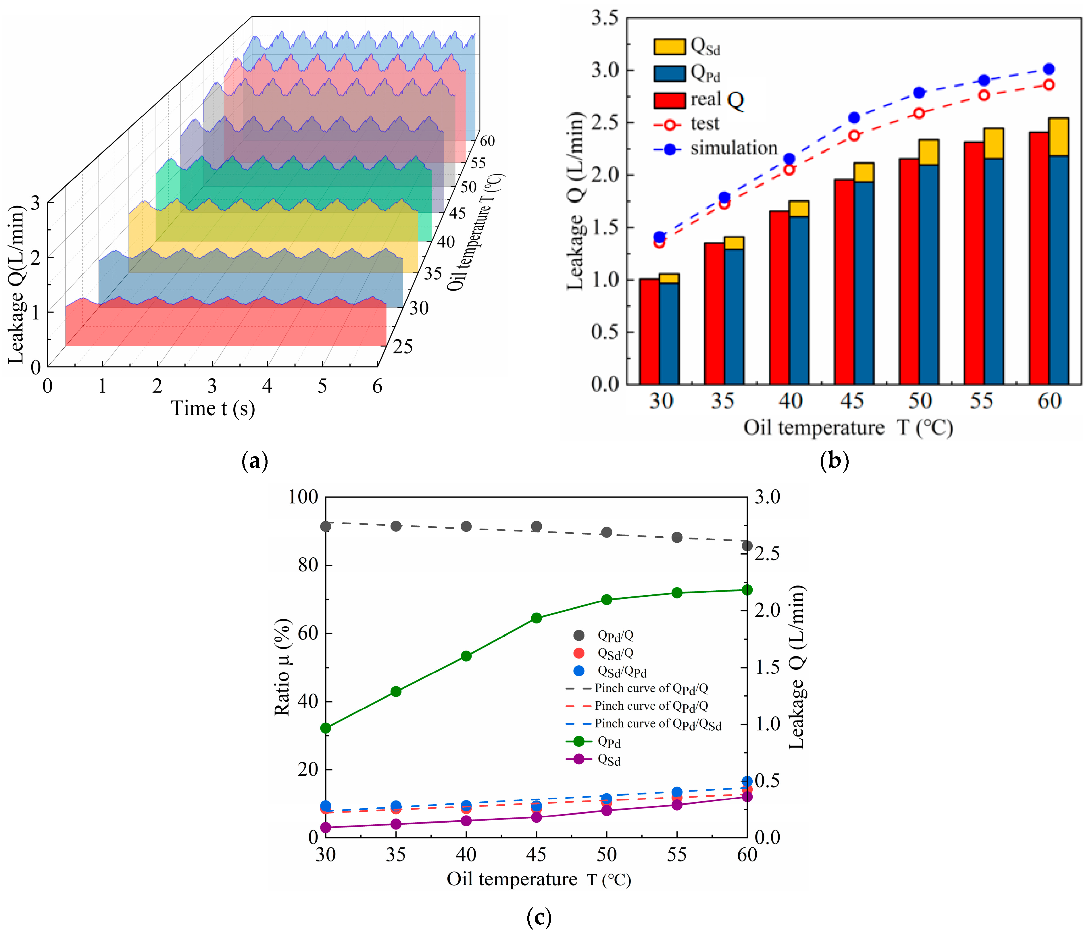
4.1.3. Influence of Oil Temperature on the Internal Leakage of the ICM

As shown in Figure 10, when the ICM inlet pressure was 24 MPa and the rotational speed was 5 r/min, with six different oil temperatures, the internal leakage of the ICM increased and the amplitude of leakage flow pulsated with oil temperature, while the pulsation frequency remained constant. As shown in Figure 10a, as the oil temperature increases, the internal leakage of the ICM increases linearly, and the calculated leakage values are higher than the measured values owing to factors such as heat absorption by the ICM structure, piping, and other system components. As shown in Figure 10b, the temperature of the oil entering the ICM was lower than that measured in the tank. The simulation process did not account for this when the oil temperature was less than 40 °C, and the error between the test and calculated values was less than 5%. When the oil temperature was greater than or equal to 40 °C, the error between the calculated and test values was greater than 5%. The linear trend between the calculated and test values was approximate. When the oil temperature was 30 °C, the leakage of the valve pair was 0.967 L/min, whereas the leakage of the plunger pairs was 0.0905 L/min. When the oil temperature was 60 °C, the leakage of the valve pair was 2.1822 L/min, that of the plunger pairs was 0.3619 L/min, and the internal leakage of the ICM showed an increasing trend with the pace at which the oil temperature changed. As shown in Figure 10c, the leakage of the valve pair as a proportion of the ICM leakage has a minimum value of 85.6% and a maximum value of 91.4%, with an increase in oil temperature showing a downward trend. The leakage of the plunger pairs as a proportion of the ICM leakage has the minimum value of 8.6% and the maximum value of 14.4%, and shows an upward trend with the increase in oil temperature. Therefore, the ratio of plunger pair leakage to valve pair leakage increased with temperature, and the trend of increasing plunger pair leakage in the overall ICM leakage. As a result, the effect of the oil temperature on the internal leakage of the ICM was apparent. As the oil temperature increases, the ratio of valve pair leakage in the internal leakage of the ICM decreases, while the ratio of plunger pair leakage in the internal leakage of the ICM increases.
In summary, the inlet pressure, rotational speed, and oil temperature have a direct effect on the internal leakage of the ICM, and the proportion of leakage of the valve pair in the internal leakage of the ICM decreased as the inlet pressure and rotational speed increased, whereas the proportion of leakage of the plunger pairs in the internal leakage of the ICM increased as the oil temperature increased. The factors affecting the internal leakage of the ICM include the inlet pressure, oil temperature, and rotational speed, in descending order, by analyzing the internal leakage of the ICM, the leakage of the valve pair and plunger pairs, and the percentage of each leakage.

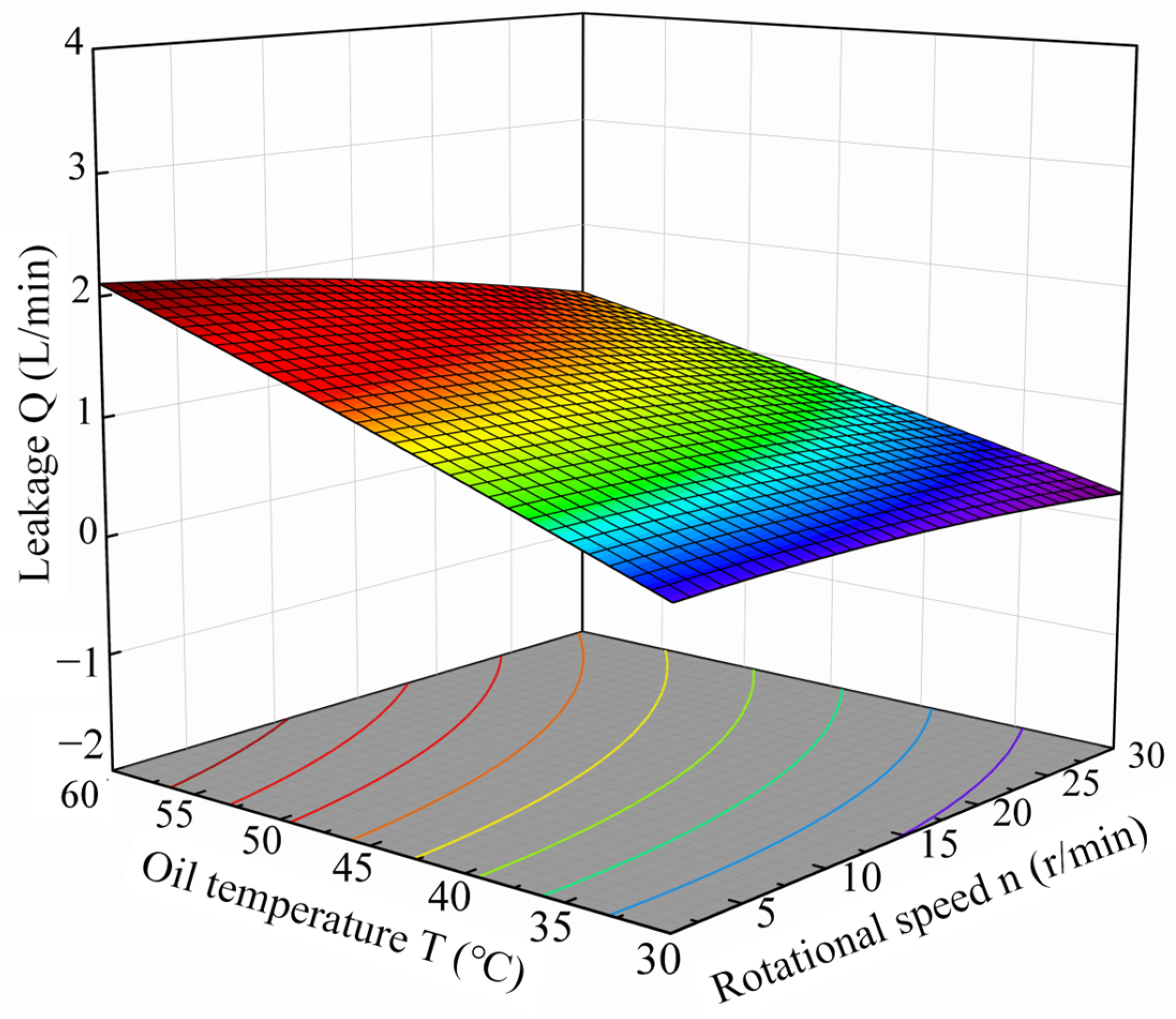
4.2. Simulation and Study of Multi-Factor Working Conditions

To investigate the relationship between the factors influencing the internal leakage of the ICM under multi-factor working conditions, the response surface method (RSM) was used to solve the response value of each factor level and analyze the relationship between their interactions. Simulation tests were performed on the model according to the principle of orthogonal experimental design [39,40] using the Box–Behnken design (BBD) in Design Expert 13 software, with inlet pressure, rotational speed, and oil temperature as the independent variables, and the internal leakage of the ICM as the response value. The simulation tests obtained different response values, as shown in Table 2.
The multivariate quadratic regression response surface model of the factors influencing the amount of leakage in the ICM was obtained using multivariate linear regression and binomial pinching of the test data. As indicated in Table 3, as can be seen from the regression model of variance results, the p-value of the model is 0.0007, indicating that the regression equation is significant at a level of 0.05. This confirms the reliability of the experimental design and the accuracy of the model in representing the relationship between the oil temperature, rotational speed, and inlet pressure on the ICM internal leakage. The p-value of the lack-of-fit term was 0.0920, suggesting that the model adequately described the experimental data. The model obtained a coefficient of determination R2 (0.9533) and adjusted R2 (0.8932) close to 1, with an accuracy of 14.18, indicating that the approach of combined computation of transient pressure in the ICM plunger chamber and the mathematical model of internal leakage of the ICM has a high level of reliability.
According to ANOVA, the significance level p-value indicates that the ICM inlet pressure and oil temperature have a significant effect on the amount of internal leakage, and the degree of their influence is the inlet pressure, oil temperature, and rotational speed, in descending order, and the model of ANOVA results are consistent with the results of the one-factor simulation test. The interaction between inlet pressure and oil temperature AC is significant (p < 0.05), indicating that inlet pressure and oil temperature have an important impact on the internal leakage of the ICM, but that the interaction with rotational speed is not significant.
Response surface graphs of the impact factor interaction effects were obtained based on the model analysis’ findings. As shown in Figure 11, in the 3D surface response diagram of the interaction between the inlet pressure and the oil temperature, the inlet pressure influence surface was steeper, and the number of contours increased along the direction of the inlet pressure. This demonstrates that the impact of oil temperature on ICM leakage is less than that of inlet pressure.
As shown in Figure 12, in the 3D surface response diagram of the interaction between the oil temperature and rotational speed, the oil temperature influence surface is steeper, and the number of contours increases along the direction of the oil temperature. This indicates that the impact of the rotational speed on the internal ICM leakage is less than that of the oil temperature.
As shown in Figure 13, in the 3D surface response diagram of the interaction between the rotational speed and inlet pressure, the inlet pressure influence surface was steeper, and the number of contours increased along the direction of the inlet pressure. This implies that the impact of the rotational speed on ICM leakage is less than the impact of the inlet pressure.
As the input pressure, rotational speed, and oil temperature increased, the effect surface rapidly increased, indicating that the combination of the two influencing components had a significant impact on the internal leakage of the ICM. Therefore, the order of the interaction strength, from strongest to weakest, is AC (inlet pressure and oil temperature), AB (inlet pressure and rotational speed), and BC (oil temperature and rotational speed). The rotational speed shows a less clear interaction effect compared to the strong interaction between inlet pressure and oil temperature, which significantly influences ICM leakage. The response surface analysis results corroborate the ANOVA results, validating the model’s accuracy and reliability in predicting ICM internal leakage.
In summary, using a combined approach of transient plunger chamber pressure and leakage mathematical modeling to accurately calculate the ICM internal leakage and the leakage of the valve and plunger pairs is correct and feasible. The RSM analysis revealed a significant interaction between the inlet pressure and oil temperature, whereas the interaction of rotational speed with either inlet pressure or oil temperature was insignificant.

5. Conclusions

The working principle of the ICM states that internal leakage is one of the primary elements affecting the power output and volumetric efficiency. In this study, a full fluid domain simulation model of the ICM was established to obtain the transient pressure of the plunger cavity through transient simulation, and the transient pressure value was combined with the leakage mathematical model to calculate the internal leakage of the ICM. One-factor working conditions were used to analyze the internal leakage of the ICM, leakage of valve pairs, and plunger pairs. Multi-factor working conditions were used to analyze the significance of interactions between factors affecting ICM internal leakage. The following conclusions were drawn from the simulations, calculations, and experiments:
  • Based on the working principle of the ICM, the motion state of the plungers is controlled by the UDF, which solves the problem of the 16 plungers performing both radial reciprocating and rotating motions. The full fluid domain of the ICM was constructed in Fluent, and a transient simulation of the ICM was realized. Its feasibility and reliability were verified by grid and time independence, and the transient pressure of the plunger chamber was obtained.
  • As the inlet pressure increased, the pulsation frequency and amplitude of the internal leakage of the ICM did not change significantly, the leakage of the valve pair and the plunger pair increased, the proportion of the valve pair leakage in the ICM leakage decreased, and the proportion of the plunger pair leakage in the ICM leakage increased.
  • As the rotational speed increased, the pulsation frequency of the internal leakage of the ICM increased, and the leakage of the valve pair tended to be almost flat when the rotational speed was increased to 20 r/min. The leakage of the plunger pair increased slightly, the proportion of the leakage of the valve pair in the internal leakage of the ICM increased, and the proportion of the leakage of the plunger pair in the internal leakage of the ICM decreased. The leakage of the plunger pair remains unchanged under different rotational speed conditions, and the effect of the rotational speed on the leakage of the plunger pair is not significant.
  • As the oil temperature increases, the pulsation amplitude of the ICM leakage decreases, the leakage of the valve pair and plunger pair increases, the proportion of the valve pair leakage in the ICM leakage decreases, and the proportion of the plunger pair leakage in the ICM leakage increases.
  • ANOVA analysis of the model revealed that the inlet pressure, oil temperature, and rotational speed influenced motor leakage, in descending order of impact. However, the rotational speed had no significant effect on the internal leakage. The response surface confirmed this, indicating a significant interaction between inlet pressure and oil temperature, but a negligible interaction between rotational speed and either inlet pressure or oil temperature. This is consistent with the ANOVA results.
In our future work, based on the internal leakage characteristics of ICMs and the conclusions of this study, we will study in depth the suitability of the floating flow distribution structure and the applicability of the valve pair. Ultimately, we aim to reduce the internal leakage, improve the performance of ICMs, and provide theoretical support for ICM design and optimization.

Author Contributions

Conceptualization, W.M., G.Y. and W.C.; methodology, W.M. and G.Y.; investigation, W.C., G.B. and C.C.; resources, W.M., C.C. and S.S.; writing—original draft preparation, W.C. and S.S.; writing—review and editing, W.M. and G.Y.; project administration, G.Y.; funding acquisition, W.C. All authors have read and agreed to the published version of the manuscript.

Funding

This research was funded by the Open Foundation of the State Key Laboratory of Fluid Power and Mechatronic Systems, grant number 2022YFC2805702.

Institutional Review Board Statement

Not applicable.

Informed Consent Statement

Not applicable.

Data Availability Statement

The original contributions presented in the study are included in the article, further inquiries can be directed to the corresponding author.

Conflicts of Interest

We declare that we do not have any commercial or associative interests that represent any conflicts of interest in connection with the work submitted.

References

  1. Ye, S.; Zhang, J.; Xu, B.; Zhu, S.; Xiang, J.; Tang, H. Theoretical Investigation of the Contributions of the Excitation Forces to the Vibration of an APP. Mech. Syst. Signal Process. 2019, 129, 201–217. [Google Scholar] [CrossRef]
  2. Lyu, F.; Zhang, J.; Sun, G.; Xu, B.; Pan, M.; Huang, X.; Xu, H. Research on Wear Prediction of plunger/Cylinder Pair in APP. Wear 2020, 456–457, 203338. [Google Scholar] [CrossRef]
  3. Banaszek, A. Identification of Optimal Efficiency Exploitation Conditions of Axial-plunger Hydraulic Motor A2FM Type Using Artificial Neural Network Algorithms. Procedia Comput. Sci. 2021, 192, 1532–1540. [Google Scholar] [CrossRef]
  4. An, G.; Wang, W.; Dong, H.; Liu, B.; Song, W.; Hu, Z. Parameter Optimization of Vibration Reduction Structure for Low-Speed, Multi-Acting Cam Ring Motor. Actuators 2023, 12, 388. [Google Scholar] [CrossRef]
  5. Ceschini, L.; Marconi, A.; Martini, C.; Morris, A. Tribological Behavior of Components for Radial plunger Hydraulic Motors: Bench Tests, Failure Analysis and Laboratory Dry Sliding Tests. Wear 2013, 305, 238–247. [Google Scholar] [CrossRef]
  6. Wang, H. Structure Optimization Design Approach of Friction Pairs for Low-Temperature Rise Wet Brake in Hydraulic Motor. Case Stud. Therm. Eng. 2024, 61, 104841. [Google Scholar] [CrossRef]
  7. Tang, S. A Light Deep Adaptive Framework toward Fault Diagnosis of a Hydraulic plunger Pump. Appl. Acoust. 2024, 217, 109807. [Google Scholar] [CrossRef]
  8. Qing, L.; Gu, L.; Wang, Y.; Lei, Z. Analysis of Leakage Characteristics for Bent-Axis plunger Pump Based on Elasto-Hydrodynamic Deformation. ILT 2022, 74, 18–25. [Google Scholar] [CrossRef]
  9. Bao, Q.; Zhou, J.; Jing, C.; Zhao, H.; Wu, Y.; Zhang, Z. Nonlinear Dynamic Model for the Free Rotor of the Swash Plate-Rotating Hydraulic Transformer. Energy 2022, 261, 125355. [Google Scholar] [CrossRef]
  10. Ma, H. Modeling and Analysis of the Leakage Performance of the Spherical Valve Plate Pair in axial piston pump. Eng. Sci. Technol. Int. J. 2023, 45, 101498. [Google Scholar] [CrossRef]
  11. Yin, F.; Nie, S.; Ji, H.; Huang, Y. Non-Probabilistic Reliability Analysis and Design Optimization for Valve-Port Plate Pair of Seawater Hydraulic Pump for Underwater Apparatus. Ocean Eng. 2018, 163, 337–347. [Google Scholar] [CrossRef]
  12. Zhao, K.; Wang, C.; He, T.; Luo, G.; Qin, Y.; Fang, S. Theoretical and Experimental Study on Lubrication and Friction of Slipper Pair of Valve Distribution plunger Pump Based on FVM-TRD Coupling Method. Tribol. Int. 2024, 194, 109456. [Google Scholar] [CrossRef]
  13. Zhang, C.; Zhang, X.; Dong, P.; Zhang, H.; Zheng, Z.; Zhang, J.; Xu, B. Composite Thermal Oil Film Lubrication Model for Hybrid Journal Bearings. Tribol. Int. 2024, 194, 109556. [Google Scholar] [CrossRef]
  14. Zhang, X. Supervised Adaptive Method for Robust and Fast Solving of Lubrication Problems. Tribol. Int. 2025, 201, 110191. [Google Scholar] [CrossRef]
  15. Isaksson, P.; Nilsson, D.; Larsson, R. Elasto-Hydrodynamic Simulation of Complex Geometries in Hydraulic Motors. Tribol. Int. 2009, 42, 1418–1423. [Google Scholar] [CrossRef]
  16. Li, Y.; Cui, X.; Zhang, J. A Study on Improving Friction and Wear Performance of Bearing Bush in Radial plunger Hydraulic Motor. Wear 2024, 546–547, 205317. [Google Scholar] [CrossRef]
  17. Wu, T.; Zhang, J.; Li, R.; Yuan, W.; Sun, Q.; Chen, S.; Li, D.; Sun, Y. Analysis and Optimization of Flow Field Characteristics of Axial plunger Motor Based on CFD. Flow Meas. Instrum. 2024, 99, 102669. [Google Scholar] [CrossRef]
  18. Li, C.; Jiang, T.; Liu, C.; Xu, H.; Shi, G. Investigation of the Leakage in the Flow Distribution Pair of Radial plunger Hydraulic Motors through CFD Analysis and Experiments. Flow Meas. Instrum. 2024, 96, 102555. [Google Scholar] [CrossRef]
  19. Xiao, C.; Tang, H.; Ren, Y.; Xiang, J.; Kumar, A. Adaptive MOMEDA Based on Improved Advance-Retreat Algorithm for Fault Features Extraction of APP. ISA Trans. 2022, 128, 503–520. [Google Scholar] [CrossRef]
  20. Ma, H.; Liu, W.; Wu, D.; Yang, B.; Xia, Y.; Xia, S. An In-Situ Measurement Approach for the Oil Film Characteristics of the Spherical Valve Plate Pair in APP. Measurement 2024, 226, 114113. [Google Scholar] [CrossRef]
  21. Sun, Y.-N.; Gao, D.-R.; Zhang, Z.-Y.; Zhao, J.-H.; Chen, B. Leakage and Permeability Characteristics of Seawater with Different Concentrations at the Distribution Windows of Variable Motor Pumps for Seawater Desalination. Desalination Water Treat. 2021, 230, 116–128. [Google Scholar] [CrossRef]
  22. Wang, L.; Deng, H.-s.; Guo, Y.-c.; Wang, C.-l.; Hu, C. Lubrication Characteristics of External Return Spherical Hinge Pair of axial piton pump or Motor under Combined Action of Inclination and Offset Distance. J. Cent. South Univ. 2021, 28, 2375–2393. [Google Scholar]
  23. Haidak, G.; Wei, X.; Li, F.; Larbi, A.; Wang, D. Heat Effects Modeling on the Efficiency Loss of the Lubricating Interface between plunger and Cylinder in APP. Tribol. Int. 2022, 175, 107846. [Google Scholar] [CrossRef]
  24. Zhang, X.; Wu, H.; Chen, C.; Wang, D.; Li, S. Oil Film Lubrication State Analysis of plunger Pair in plunger Pump Based on Coupling Characteristics of the Fluid Thermal Structure. Eng. Fail. Anal. 2022, 140, 106521. [Google Scholar] [CrossRef]
  25. Bergada, J.M.; Kumar, S.; Davies, D.L.; Watton, J. A Complete Analysis of APP Leakage and Output Flow Ripples. Appl. Math. Model. 2012, 36, 1731–1751. [Google Scholar] [CrossRef]
  26. Zhang, B.; Hong, H.; Ma, J.; Yang, H.; Fang, Y. Analysis of the Flow Dynamics Characteristics of an APP Based on the Computational Fluid Dynamics Method. Eng. Appl. Comput. Fluid Mech. 2017, 11, 86–95. [Google Scholar]
  27. Kumar, N.; Kumar, R.; Sarkar, B.K.; Maity, S. Condition Monitoring of Hydraulic Transmission System with Variable Displacement APP and Fixed Displacement Motor. Mater. Today Proc. 2021, 46, 9758–9765. [Google Scholar] [CrossRef]
  28. Sun, Z.; Zeng, Q.; Wan, L. An Indirect Flow Measurement Method for Bi-Tandem APP Based on Leakage Flow Estimation. Measurement 2024, 229, 114473. [Google Scholar] [CrossRef]
  29. Phan, V.D.; Vo, C.P.; Dao, H.V.; Ahn, K.K. Actuator Fault-Tolerant Control for an Electro-Hydraulic Actuator Using Time Delay Estimation and Feedback Linearization. IEEE Access 2021, 9, 107111–107123. [Google Scholar] [CrossRef]
  30. Ma, K. Experimental Investigation and Theoretical Evaluation on the Leakage Mechanisms of Seawater Hydraulic APP under Sea Depth Circumstance. Eng. Fail. Anal. 2022, 142, 106848. [Google Scholar] [CrossRef]
  31. AbdulGafoor, C.P.; Rajananda, A.; Shankar, A.; Vadlamani, N.R. Entropy Damping and Bulk Viscosity Based Artificial Compressibility Methods on Dynamically Distorting Grids. Comput. Fluids 2024, 279, 106328. [Google Scholar] [CrossRef]
  32. Li, Y.; Ji, Z.; Yang, L.; Zhang, P.; Xu, B.; Zhang, J. Thermal-Fluid-Structure Coupling Analysis for Valve Plate Friction Pair of APP in Electro-hydrostatic Actuator (EHA) of Aircraft. Appl. Math. Model. 2017, 47, 839–858. [Google Scholar] [CrossRef]
  33. Zhao, J. Review of Cylinder Block/Valve Plate Interface in APP: Theoretical Models, Experimental Investigations, and Optimal Design. Chin. J. Aeronaut. 2021, 34, 111–134. [Google Scholar] [CrossRef]
  34. Hong, R.; Ji, H.; Nie, S.; He, H.; Guo, M.; Yin, F.; Yan, X. A Hybrid of CFD and PSO Optimization Design Method of the Integrated Slipper/Swashplate Structure in seawater hydraulic axial piston pump. Eng. Appl. Comput. Fluid Mech. 2022, 16, 2123–2142. [Google Scholar] [CrossRef]
  35. Guan, C.; Jiao, Z.; He, S. Theoretical Study of Flow Ripple for an Aviation Axial-plunger Pump with Damping Holes in the Valve Plate. Chin. J. Aeronaut. 2014, 27, 169–181. [Google Scholar] [CrossRef]
  36. Li, Y.; Yu, L.; Jiang, H.; Zhao, E. Transient Sealing Characteristics of Glyd-Ring in the High Water-Based plunger Pair under Reciprocating Pump Conditions. Tribol. Int. 2024, 192, 109293. [Google Scholar] [CrossRef]
  37. Wang, H.; Lin, N.; Yuan, S.; Liu, Z.; Yu, Y.; Zeng, Q.; Fan, J.; Li, D.; Wu, Y. Structural Improvement, Material Selection and Surface Treatment for Improved Tribological Performance of Friction Pairs in APP: A Review. Tribol. Int. 2024, 198, 109838. [Google Scholar] [CrossRef]
  38. Nie, S. Research on Fluid-Structure Interaction for plunger/Cylinder Tribo-pair of Seawater Hydraulic axial piton pump in Deep-Sea Environment. Ocean Eng. 2021, 219, 108222. [Google Scholar] [CrossRef]
  39. Liu, Z.; Li, B.; Yao, T.; Sun, M.; Wang, Y.; Niu, L.; Du, Y. Optimization of Slow-Release Salt Storage Snowmelt Aggregate Preparation Process and Its Slow-Release Performance Based on Response Surface Methodology-Orthogonal Test. Constr. Build. Mater. 2024, 449, 138356. [Google Scholar] [CrossRef]
  40. Duan, X.; Yu, H.; Wu, X.; Hu, L.; Chen, H.; Sun, Y.; Wu, B. Numerical Simulation Analysis and Orthogonal Experiment Optimization of the Factors Affecting Plasma Gasification of Oil-Based Drilling Cuttings. Int. J. Hydrogen Energy 2023, 48, 38617–38633. [Google Scholar] [CrossRef]
Figure 1. Design schematic diagram of hydraulic system: 1—variable pump; 2—displacement pump; 3—test motor; 4—loading pump; 5—flowmeter; 6—speed control valve; 7—pressure regulator valve; 8—proportional relief valve; 9—pressure sensor; 10—relief valve; 11—check valve; 12—torque speed sensor; 13—directional valve; 14—tank; 15—pressure gauge; 16—unloading valve; 17—filter; 18—drive motor.
Processes 12 02835 g001
Figure 2. The ICM leakage test bench.
Processes 12 02835 g002
Figure 3. Structure of the ICM.
Processes 12 02835 g003
Figure 4. The fluid computational domain of the ICM.
Processes 12 02835 g004
Figure 5. Pressure cloud diagram of the fluid computational domain.
Processes 12 02835 g005
Figure 6. Plunger chamber pressure under different mesh grid density.
Processes 12 02835 g006
Figure 7. Plunger chamber pressure under different time steps.
Processes 12 02835 g007
Figure 8. (a) Leakage under different inlet pressures; (b) leakage of plunger and valve pair under different inlet pressures; (c) percentage of leakage under different inlet pressures.
Processes 12 02835 g008
Figure 9. (a) Leakage under different rotational speeds; (b) leakage of plunger and valve pair under different rotational speed; (c) percentage of leakage under different rotational speed.
Processes 12 02835 g009
Figure 10. (a) Leakage under different oil temperature; (b) leakage of plunger pair and valve pair under different oil temperature; (c) percentage of leakage under different oil temperature.
Processes 12 02835 g010
Figure 11. Relationship of leakage with oil temperature and inlet pressure.
Processes 12 02835 g011
Figure 12. Relationship of leakage with oil temperature and rotational speed.
Processes 12 02835 g012
Figure 13. Relationship of leakage with rotational speed and inlet pressure.
Processes 12 02835 g013
Table 1. Corresponding parameter.
SymbolValueSymbolValue
R 1 127.4 mm D 238.6 mm
R 2 125.5 mm d 48 mm
R 3 113.3 mm μ 0.043 Pa·S
R 4 111.2 mm C e 2.2
h 0.015 mm l c 15 mm
Table 2. Experiment scheme.
Test GroupInlet Pressure P (MPa)Rotational Speed n (rpm)Oil Temperature T (°C)Leakage Q (L/min)
12215.5301.255
21330300.617
3415.5300.177
41315.5451.108
5415.5600.598
61315.5451.001
72215.5604.360
8221453.492
9131601.439
10430450.392
111330601.056
122230452.026
131315.5451.549
14131300.444
1541450.285
161315.5451.407
171315.5451.111
Table 3. Results of ANOVA of the experiment.
SourceSum of SquaresDFMean SquaresF-Valuep-Value
Model18.8992.1015.860.0007 *
A-Inlet pressure11.72111.7288.55<0.0001 *
B-Rotational speed0.3110.312.330.1710
C-Oil temperature3.0713.0723.230.0019 *
AB0.6210.624.680.0673
AC1.8011.8013.610.0078 *
BC0.0810.080.580.4699
A21.1011.108.300.0236
B20.1610.161.240.3017
C20.0910.090.710.4289
Residual0.9370.13
Lock of Fit0.7130.244.440.0920
Pure Error0.2140.05
Total19.8216
‘*’ indicates that the item is significant (p-value < 0.05).
Disclaimer/Publisher’s Note: The statements, opinions and data contained in all publications are solely those of the individual author(s) and contributor(s) and not of MDPI and/or the editor(s). MDPI and/or the editor(s) disclaim responsibility for any injury to people or property resulting from any ideas, methods, instructions or products referred to in the content.

