Article

Finite Element Simulation of Aerosol Particle Trajectories in a Cantilever-Enhanced Photoacoustic Spectrometer for Characterization of Inertial Deposition Loss

1
Department of Physics, University of Helsinki, 00560 Helsinki, Finland
2
Department of Chemistry, University of Helsinki, 00560 Helsinki, Finland
3
Atmospheric Composition Research, Finnish Meteorological Institute, 00560 Helsinki, Finland
*
Author to whom correspondence should be addressed.
Processes 2024, 12(12), 2827; https://doi.org/10.3390/pr12122827
Submission received: 4 November 2024 / Revised: 21 November 2024 / Accepted: 6 December 2024 / Published: 10 December 2024
(This article belongs to the Section Particle Processes)

Abstract

:
The cantilever-enhanced photoacoustic spectrometer is a sensitive instrument developed originally for trace gas measurements and has lately been successfully applied for measuring light-absorbing particles, such as aerosols. The finite inertia of aerosol particles can cause the particles to be deposited on the walls in the spectrometer’s flow channels, which creates a source of uncertainty for the measurement process. In this study, we characterized this inertial deposition in the spectrometer using finite element-based modeling. First, computational fluid dynamics was used to calculate the distribution of airflow within a 3D model of the spectrometer’s flow channels. Then, the trajectories of aerosol particles were computed to evaluate the inertial deposition losses. The modeling method was validated by computing inertial deposition for two known cases of laminar flow, namely particles flowing through a pipe with a 90-degree bend and a pipe with an abrupt contraction. The particle transmission of the photoacoustic spectrometer was experimentally measured. Differences and similarities between measured and modeled results are discussed. The modeled inertial deposition losses ranged from approximately 5% to 70% for particle diameters between 50 and 500 nm. This modeling approach provides valuable insight into the influence of particle size and flow rate on the inertial deposition and also pinpoints the physical location of the loss within the spectrometer, which is valuable for improving the measurement process.

Graphical Abstract

1. Introduction

The deposition of aerosol particles, which refers to a phenomenon where particles are driven and permanently adhered to nearby walls or surfaces, has been studied theoretically and experimentally for decades [1,2,3]. This is due to its importance in many different applications; for example, the characterization of sampling losses of measurement instruments in atmospheric sciences is a prerequisite for a representative quantification of particle concentrations in ambient air [4,5,6]. A recently studied technique based on photoacoustics has been shown to be suitable for atmospheric measurements of particulate matter [7,8]. In human health, particle deposition in the human respiratory system is an important field of study, as exposure to particles is highly correlated with morbidity and premature deaths. However, the mechanisms driving this morbidity and mortality are incompletely understood [9,10,11]. Furthermore, the COVID-19 pandemic further emphasized the need to understand particle deposition in human airways both in terms of pathogen deposition and in dosimetry of inhaled drugs [12,13,14]. Particle deposition is also important in many different industrial applications, ranging from gas filtration to material separation processes [15,16].
Particle deposition can be driven by a variety of forces, including inertial, diffusion, and electrostatic [17]. In general, larger particles are predominantly affected by inertial forces, whereas smaller particles are subjected to diffusion and electrostatic forces. Sampling losses can be estimated using a theoretical or experimental approach. The theoretical approach includes first-order kinetics based on fitted experimental loss coefficients [18] and the use of Computational Fluid Dynamics (CFD) modeling in combination with particle tracking [19]. Experimental characterization can be performed by comparing the measured concentration of particles flowing through the system with the concentrations when bypassing the system [20]. Another approach to quantify deposition losses is to use a fluorescence trace dye on particles and first visually inspect and then measure the concentration of dye found on washed system parts. In this way, the location and the number of deposited particles can be estimated [21].
This study presents a simulation method for calculating inertial deposition losses in a complex, multi-part aerosol measurement instrument, specifically the Cantilever-Enhanced Photoacoustic Spectrometer (CEPAS). The CEPAS measures particle light absorption, and its key distinction from conventional photoacoustic instruments lies in its detector. Instead of a traditional stretching-based microphone, the CEPAS uses a silicon cantilever whose position (i.e., bending) is optically measured with an interferometer, allowing the instrument to achieve an order of magnitude higher sensitivity than conventional instruments [8]. Although the CEPAS is relatively new, its exceptional sensitivity is expected to make it increasingly important in aerosol research, opening new possibilities in previously unattainable measurement applications, such as measurements of extremely low concentrations in arctic regions. Accordingly, it is important to characterize the particle deposition losses of the CEPAS. This ensures that the instrument obtains a representative quantification of particle concentrations.
The simulation model used to calculate deposition losses was first validated using two simplified configurations, specifically a bent section and an abrupt contraction of a pipe. The model’s accuracy was validated by comparing its results to the existing literature. After validation, the deposition simulation was applied to the CEPAS instrument. To further evaluate the accuracy of the model and to assess the CEPAS sampling losses, experimental measurements of particle losses were also conducted. The objective of the study is to not only quantify the total losses but also to define the physical locations where they occur. The locations of losses are of importance for defining their precise impact on the instrument’s measurement process.

2. Materials and Methods

2.1. Flow System of a CEPAS

The flow channels of the CEPAS instrument consist of a 3D system involving multiple turns, contractions, and expansions. The instrument was originally designed for gas-phased measurements, and its particle-phased losses are characterized here. The sampling system, including inlet and outlet pipes, is shown in Figure 1a. In the system, the flow first encounters a 90-degree tube fitting used to fix the tubing to the sample cell body. From there, the flow enters into a valve housing part and makes two consecutive 90-degree turns before reaching the acoustic sample chamber. The acoustic sample chamber is the long cylindrical pipe shown in the central-upper part of Figure 1a. At the end of the sample chamber, the flow encounters the same parts in reverse order, from where it flows to the outlet pipe. The inlet and outlet pipes have an inside diameter of 2.2 mm. A detailed view of the tube fitting and valve housing part is shown in Figure 1b.
The experimental particle deposition measurements of the CEPAS sampling system were performed using an atomizer (model ATM 226, Topas GmbH, Dresden, Germany) to generate NH4NO3 solid particles (density 1720 kg / m 3 ) and then feeding them either through the CEPAS or through a bypass line to a particle number concentration counter (Condensation Particle Counter model 3776, TSI Inc., Shoreview, MN, USA). The choice of NH4NO3 was motivated by its availability and well-known material properties. The ratio between the measured particle concentrations fed through the CEPAS and through the bypass line was calculated to be the transmission efficiency of particles. Measurements were performed for six different particle sizes (50, 100, 200, 300, 400, and 500 nm) by using a particle size classifier (Differential Mobility Analyzer 3080, TSI Inc., USA) in line after the atomizer. Particles of such sizes are representative of the exhaust gases from combustion engines that would be measured with the photoacoustic technique. In the main case of interest, the sample flow through the system was 1.5 L / min . Additional measurements using 0.3 L / min were also performed. An individual measurement point was obtained by feeding particles through the system and manually operating a three-way valve between the CEPAS and bypass lines; once the measured particle concentration stabilized at a given measurement point, the three-way valve was switched and the measurement was then repeated. Measuring concentrations both through the CEPAS and bypass lines constituted a single measurement point. Measurements were repeated five times for all particle sizes altogether. TSI AIM software (version 10) was used to record the particle number concentration readings.
Numerical simulations of fluid flow and particle tracing were performed using the 3D geometry shown in Figure 1. In these simulations, we adopted the parameters for the flow and particles used in the experimental measurements. This was conducted to compare simulated and experimental results. The modeled air flow has a constant-valued volumetric flow rate of 1.5 L/min, which corresponds to a flow Reynolds number that is smaller than 1000. The flow carries NH4NO3 particles of varying size. We assumed the density of the particles to be that of bulk NH4NO3 ( ρ p = 1720   kg / m 3 ) and the shape of the particles to be spherical with diameter d p . We consider these assumptions reasonable in order to streamline the calculation procedure. Our method calculates the trajectories of particles through the flow system, from which the transmission can be evaluated, which is equal to the fraction of particles that reached the system outlet. The background fluid is air at standard temperature and pressure.
The numerical simulations were performed using a desktop computer with AMD Ryzen 9 7900X 12-Core Processor (base speed 4.7 GHz) and 128 GB of DDR5 RAM. The number of mesh elements that could be used in the fluid flow calculation was limited by the available RAM. In the particle trajectories calculation, the total number of particles and the solver’s time-step size were chosen such that the calculation time with the employed processor would be convenient. A convenient calculation time was decided to be about one day.

2.2. Fluid Flow Model

The flow field was calculated by solving the incompressible Navier–Stokes equations
ρ 0 u t + ρ 0 u u = p + μ 2 u ,
ρ 0 u = 0 ,
for the flow velocity u and relative pressure p . We considered the fluid density ρ 0 and dynamic viscosity μ to be constant-valued material parameters. The equations were solved using the Finite Element Method (FEM) in COMSOL Multiphysics® version 6.2. The software has built-in numerical stabilization (streamline and crosswind diffusion) that is needed to solve the equations. A fully developed flow corresponding to a known volumetric flow rate was prescribed at the inlet and the condition p = 0 was prescribed at the outlet. A no-slip wall condition, u = 0 , was prescribed on all solid boundaries. We evaluated the flow Reynolds numbers to be close to 1000 in our case of interest. This means that the flow regime is either laminar or transitional. Therefore, it was not needed to use a turbulence model. In the transitional regime, the flow can be calculated by the transient laminar Equations (1) and (2), but this may not have a steady-state solution. This transient laminar flow regime was previously observed by Novosselov et al. [22], where they simulated inertial deposition in curved flow channels. They reported that a comparison between transient laminar and detached eddy simulations showed less than a 5% difference in particle deposition for flow Reynolds numbers less than 2300. We used a time-dependent solver employing a scheme of Backward Differentiation Formula (BDF). This is the default solver in the software. To improve convergence of the time-dependent solver, the volumetric flow rate was prescribed as a smoothed step function that grows from zero to the desired value over a finite time. Only the flow field at the final time is used for the subsequent particle trajectories calculation.
The FEM is based on dividing the geometrical domains into mesh elements. Within each element, the dependent variables u and p are expressed by polynomials. We used the so-called P1/P1 formulation, which indicates that both u and p are linear polynomials. The numerical stabilization algorithm adds diffusion locally to each mesh element. The smaller the mesh element, the less diffusion is added. We observed that when reducing the mesh element size, it becomes increasingly difficult for the solution to converge. This can be understood as a consequence of the reduction in local numerical diffusion, which causes the flow solution to lose stability. This is problematic since we observed that a very small mesh element size is required for the subsequent particle trajectories calculation to be accurate. For the 3D model of the CEPAS, the fluid flow computation fails to converge when using a fine mesh. The convergence problem could be avoided with a two-step approach. First, the fluid flow model was initially solved with a coarser mesh (2.2 million volumetric elements) and then the obtained solution was used as initial values for a second computation with a fine mesh (18.8 million volumetric elements). In the second computation, the time-dependent solver calculated a time interval of 0.1 milliseconds by taking 32 time steps.

2.3. Particle Trajectories Model

The trajectories of particles were computed using Newtonian particle tracing within the same software that computed the flow field. We released 1000 particles at the flow inlet and computed their trajectories using a time-dependent solver employing the generalized-alpha scheme (this is the default solver in the software). The particles were given an initial velocity equal to the local fluid flow velocity and their spatial distribution at the inlet was proportional to the magnitude of the local fluid flow velocity. The particles were subjected to a drag force by the fluid. The drag force used in the model is
F = 1 τ C m p ( u v ) ,
where v is the particle velocity and m p is the particle mass. The particle velocity response time τ is defined as
τ = 4 ρ p d p 2 / ( 3 μ C D Re r ) ,
where the relative Reynolds number is
Re r = ρ 0 u v d p / μ .
The drag coefficient C D was set to be a piecewise function of the relative Reynolds number using the option Standard Drag Correlations in the particle tracing module of COMSOL Multiphysics version 6.2. Equation (3) also contains the slip correction factor C that is given by the Cunningham–Millikan–Davies model
C = 1 + Kn · C 1 + C 2 e C 3 / Kn ,
where Kn is the Knudsen number and the coefficients have values C 1 = 1.142 , C 2 = 0.558 , and C 3 = 0.999 [23]. The particle Knudsen number can be calculated by
Kn = 2 μ d p π 2 ρ 0 p 0 ,
which is evaluated for air at atmospheric pressure p 0 = 101.3   kPa , having a dynamic viscosity μ = 1.814 · 10 5   Pa · s and density ρ 0 = 1.2   kg / m 3 .
Particles were set to stop upon collision with a wall. Only particles that passed from the flow inlet to the outlet without any wall collisions were considered as transmitted. The system transmission was defined as the ratio of particles reaching the outlet relative to the total amount of particles released at the inlet. The particles that stopped at a wall can be visualized by the software to observe where the losses occur. The software also has a summation operator that allows evaluating the number of particles residing within each geometrical domain at any given instance of time.

2.4. Validation Examples

For a simulation method to be considered reliable, it should be able to produce results that are consistent with the published literature. For simple geometries, sampling losses can be predicted using analytical formulas. Many such formulas are available in the “AeroCalc” Excel spreadsheet by Paul Baron [24] and included in the software tool “Particle Loss Calculator” [25]. We considered two well-known examples of inertial deposition to validate our modeling method. These are particle transmission through a pipe with a 90-degree bend [26] and through a pipe with an abrupt contraction [27]. Such features are also found in the CEPAS sampling system.
Particle transmission is often reported as a function of the Stokes number. Different definitions of the Stokes number can be found in the literature. For example, it can be defined with respect to either a pipe radius or diameter. In this study, we considered the flow channels to have circular cross-sections at the inlet and outlet. We choose to define the Stokes number with respect to the inside diameter of the outlet D by
S t k = C ρ p d p 2 18 μ U ave D ,
where ρ p and d p are the density and diameter of the particles, respectively. The fluid has a dynamic viscosity μ . The average flow velocity U ave is evaluated at the inlet.
The first validation example considers particles flowing through a bent pipe. The pipe has a circular cross-section and has a 90-degree bend. Pui et al. [26] defined several experimental test cases of inertial deposition in such a bent pipe. We considered the case with a pipe inside diameter of 5 mm, curvature ratio 5.7, and flow Reynolds number of 1000. The curvature ratio is defined as the bend’s radius of curvature divided by the inside radius of the pipe cross-section. The particles have a density of ρ p = 1   g / c m 3 .
Inertial deposition in a bent pipe for laminar flow conditions was measured by Pui et al. [26]. An empirical fit to these data can by expressed by the equation
η = 1 + S t k 0.171 0.452 · S t k 0.171 + 2.242 2 θ / π ,
where the transmission η is expressed through the Stokes number S t k and angle of the bend θ [17]. This example was recently investigated and very good agreement with the original measurement data was reported [28].
The “AeroCalc” Excel spreadsheet [24] uses an older equation by Crane and Evans [29]:
η = 1 S t k θ .
For the validation example of a bent pipe, we compared the results of our numerical method to the predictions provided by both Equations (9) and (10).
The second validation example considers a pipe that is connected to a narrower pipe by an abrupt contraction. Both pipes have a circular cross-section, and a contraction ratio equal to 2 was considered. The contraction ratio is the inside diameter of the inlet pipe divided by the inside diameter of the outlet pipe. The problem setup is fully described in the original article by Ye and Pui [27]. We considered the inlet pipe to have an inside diameter of 5 mm and a flow Reynolds number of 1000. The particles had a density of ρ p = 1   g / c m 3 .
If the particle distribution at the inlet follows the fully developed laminar flow profile, then we can use the following equation for transmission:
η = 1 1 D o D i 2 1 exp 1.721 8.557 x + 2.227 x 2 2 ,
where D o and D i are the inside diameters of the outlet and inlet pipes, respectively [27]. The intermediate parameter x depends on the Stokes number from the equation
x = D o D i 0.31 S t k .
The Stokes number used in Equation (12) is defined using D o in place of D in Equation (8). The fit provided by Equation (11) is only valid when x < 1.95 . For larger values of x , the transmission is set to the constant value
η = 1 1 D o D i 2 2 .
For values of x < 0.213 , the transmission is set to 100%. For the validation examples of an abrupt contraction, we compared the results of our numerical method to the prediction provided by Equation (11).

3. Results and Discussion

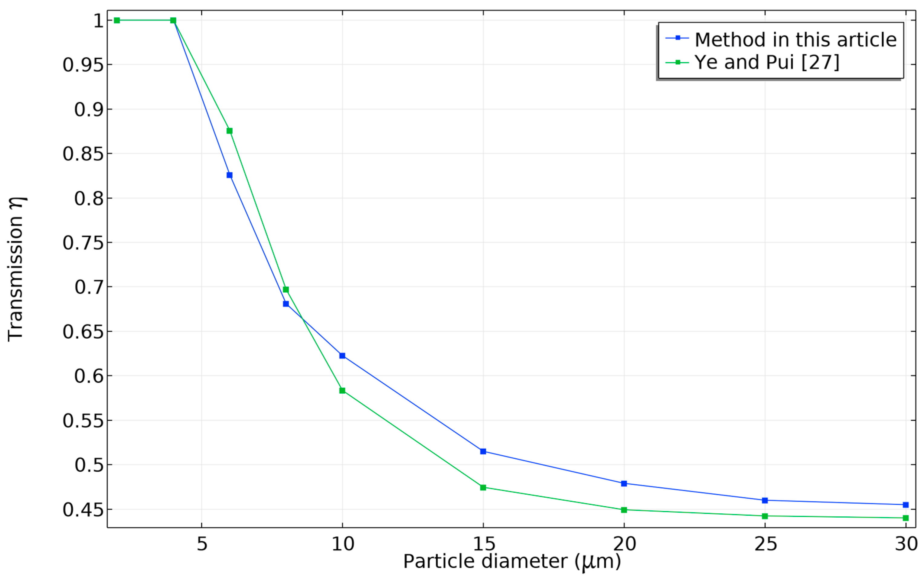
3.1. Results for Validation Examples

The first validation example considered particles flowing through a 90-degree bend. A mesh consisting of 237,783 volumetric elements was used, resulting in a calculation time of 13 min for the flow field and 7 min for the particle trajectories. The particle trajectories were computed sequentially for particles of 24 different diameters. The calculated velocity magnitude distribution is shown in Figure 2. We observed that the flow profile is laminar in the straight portions. The effect of inertia made the flow curve towards the outer surface at the location of the bend. A cross-sectional cut of the mesh is also shown in Figure 2. The tetrahedrons are larger in the central portion of the pipe. The thick lines seen near the solid boundaries contain a boundary layer mesh consisting of 10 layers of prism elements. The mesh was chosen based on the laminar flow and it can be observed in Figure 2 that it fully resolves the flow features in the geometry.
The calculated transmission as a function of particle diameter is shown in Figure 3 (blue curve). We observed that the results closely followed Equation (9), which is a fit to the experiments performed by Pui et al. [26]. Equation (10) by Crane and Evans [29] produced results that deviated significantly from our method.
The second validation example considered particles flowing through an abrupt contraction. A mesh consisting of 475,666 volumetric elements was used, resulting in a calculation time of 16 min for the flow field and 3 min for the particle trajectories. The particle trajectories were computed sequentially for particles of nine different diameters. The calculated velocity magnitude distribution is shown in Figure 4. We observed that the flow profile was laminar in the straight portions. However, at the location of the contraction, the velocity magnitude increased near the contraction corner. For the subsequent particle tracing to be accurate, it is important that the mesh accurately resolves the flow distribution near the corner. A cross-sectional cut of the mesh is also shown in Figure 4. The thick lines seen near the solid boundaries contain a boundary layer mesh consisting of 10 layers of prism elements. It can be observed in Figure 4 that the mesh fully resolves the flow features in the geometry.
The calculated transmission as a function of particle diameter is shown in Figure 5 (blue curve). We observed that the results closely followed Equation (11) derived in Ye and Pui [27]. Their model also considered inertial interception, which was not included in our method. However, they found that interception only had a minor effect.

3.2. Inertial Deposition in CEPAS

The modeling method validated by the simple examples was applied to the 3D model of the CEPAS instrument. The initial flow field with a coarser mesh of 2.2 million volumetric elements had a calculation time of 14 min. The subsequent flow field calculation with a finer mesh of 18.8 million volumetric elements was run for 12 h and 44 min, corresponding to 32 time steps taken by the solver. During the computation, 108 GB of RAM was used during the most memory-intensive part. The flow resolved by the finer mesh was observed to be in the transitional regime. The flow field at the final time step was considered representative of the flow and used for the particle trajectories calculation. The particle trajectories were computed sequentially for particles of 10 different diameters. The total calculation time for the trajectories was 20 h and 46 min.
The calculated transmission as a function of particle diameter is shown by the blue curve in Figure 6. This is the main case using a volumetric flow rate of 1.5 L / min . We observed that the transmission decreased monotonically with increasing particle size. The experimentally measured transmission is shown by the green curve in Figure 6. Both the calculated and measured curves reduced monotonically at similar rates within the considered range of particle diameters. This similarity confirms that the experimentally observed particle size dependence is dominated by inertial deposition. However, the measured transmission curve began at a lower level than the calculated curve. For the smallest particle diameter of 50 nm, the measured loss was already 18%. Overall, the results in Figure 6 indicate that the chosen flow conditions would cause inertial deposition to significantly disturb the aerosol measurement process.
The numerical simulations also provided insight into the physical location where particles were lost to inertial deposition. In Figure 7, the loss was separated with respect to the geometrical part where it occurred. The localized inertial loss is here defined as the number of particles deposited within the geometrical part divided by the number of particles released at the inlet pipe. Thus, the total loss is the arithmetic sum of the localized losses. Figure 7 revealed that the main source of loss was the second 90-degree tube fitting. As the particle diameter increased beyond 200 nm, the first tube fitting also started to collect particles on its walls. Larger particles were also to a lesser extent deposited at the second valve housing. The loss was significantly larger in the components occurring after the sample tube, even though the system geometry has mirror symmetry (Figure 1). This is because inertial deposition is not symmetric with respect to the reversal of flow direction.
The results suggest that inertial deposition can be mitigated by removing the tube fittings and by reducing the flow rate. Therefore, a second case was simulated without tube fittings and with a reduced flow rate of 0.3 L / min . This setup was also measured experimentally. The calculated and measured results are shown in Figure 8. The calculated results did not indicate inertial deposition within the considered range of particle diameters. The transmission had a nearly constant value in the calculations and measurements. The experimental transmission had a small reduction at a particle diameter of 500 nm. Additional experimental measurements using even larger particles would be necessary to establish the onset of inertial deposition at this reduced flow rate. Interestingly, the experimental results showed an offset relative to the simulated results. This offset was approximately 19%, which was slightly higher than for the first case that had a higher flow rate of 1.5 L / min .
The simulated and experimental results are in good agreement for the dependence of particle transmission on particle size and flow rate. However, an offset was observed that was caused by a mechanism other than inertial deposition. Common loss mechanisms not included in the simulations are diffusion and electrostatic forces. The sampling lines were made of anti-static material to minimize the influence of electrostatic forces. To estimate the contribution of diffusion, we used the analytical equation for a long tube [30] with tube lengths set to be equivalent to the parts of our system. For the smallest particle diameter of 50 nm, the analytical equation predicted a loss of approximately 1% only. For larger particles, the diffusion loss would be even less. Thus, it appears that the experimentally observed loss offset was not caused by inertial deposition, electrostatic forces, or diffusion. Upon closer inspection, we found that the particle counter pump produced an under-pressure due to the large pressure drop of the flow through the CEPAS instrument. One hypothesis is that the under-pressure causes the counter to underestimate the particle concentrations, which results in the observed constant offset. However, such an offset should appear smaller for our measurement with reduced flow rate, which was not observed. Therefore, the reason for the offset was not confirmed. Resolving this issue would require extensive measurements. This is beyond the scope of this work, which was to characterize the effects of inertial deposition. In future work, the CEPAS could be redesigned to allow better control of pressure levels between sample input and output. The redesign could also involve flow channels of larger cross-section or the use of alternative wall materials. The simulation model can also be further refined by including dynamic effects of the transitional flow regime, which can contribute in cases of high flow rate.

4. Conclusions

Inertial deposition of aerosol particles in the CEPAS was characterized using finite element simulations. The simulation method can calculate the particle trajectories in 3D systems of arbitrary geometrical shape. All considered simulations were in the laminar flow regime, but the simulations can be further developed to include turbulence models. Validation examples were used to confirm that our method produces results consistent with previously published analytical formulas. The method was successfully applied for calculating the particle transmission in the geometrically complicated CEPAS instrument. Results were presented for flow rates corresponding to a high-flow and low-flow case. In practical use of the instrument, the low-flow case should be preferred as it reduces inertial deposition. This case also sets the operation deeper into the laminar flow regime, which helps convergence of the simulations. Although experimental measurements demonstrated a similar dependence of the transmission on the particle size, an offset was observed between the calculated and measured curves. The offset was suspected to be caused by the measurement setup. It was argued that the offset was not caused by inertial deposition.
The modeling of the photoacoustic measurement instrument allowed us to pinpoint the physical locations where the losses occur. This would have been difficult to perform experimentally without having to disassemble the instrument. We found that more loss occurred at the outlet side after the sample chamber than at the inlet side. This knowledge is useful since losses occurring at the outlet side do not affect the photoacoustic excitation in the sample cell. However, the loss occurring in the tube fitting at the inlet side was significant. Therefore, our study suggests that such fittings should preferably not be used, especially in a high-flow case.
Since the model is based on Newtonian particle tracing, the trajectories of individual particles can be observed. Therefore, we can study the distribution of particle concentration within the flow system. This is particularly helpful for photoacoustic instruments, where the optical absorption by the particles generates the photoacoustic signal. If particles have an inhomogeneous distribution along the optical path, the photoacoustic signal may not accurately represent the average concentration of particles in the system. Further research should be conducted to investigate this effect.

Author Contributions

Conceptualization, P.G. and J.K.; methodology—modeling, P.G.; methodology—experimental, J.K.; software, P.G.; validation, P.G.; formal analysis, P.G. and J.K.; investigation, P.G. and J.K.; writing—original draft preparation, P.G.; writing—review and editing, J.K.; visualization, P.G.; funding acquisition, J.K. All authors have read and agreed to the published version of the manuscript.

Funding

This work was supported by the Academy of Finland under grant 349544 and by the Jane and Aatos Erkko Foundation for the project “Compact and precise sensor for global black carbon monitoring”.

Data Availability Statement

Models including figure data are publicly available for the validation example models at the Zenodo online repository [31].

Conflicts of Interest

The authors declare no conflicts of interest.

References

  1. Belyaev, S.P.; Levin, L.M. Techniques for Collection of Representative Aerosol Samples. J. Aerosol Sci. 1974, 5, 325–338. [Google Scholar] [CrossRef]
  2. Friedlander, S.K.; Johnstone, H.F. Deposition of Suspended Particles from Turbulent Gas Streams. Ind. Eng. Chem. 1957, 49, 1151–1156. [Google Scholar] [CrossRef]
  3. Tian, L.; Ahmadi, G. Particle Deposition in Turbulent Duct Flows—Comparisons of Different Model Predictions. J. Aerosol Sci. 2007, 38, 377–397. [Google Scholar] [CrossRef]
  4. Hangal, S.; Willeke, K. Aspiration Efficiency: Unified Model for All Forward Sampling Angles. Environ. Sci. Technol. 1990, 24, 688–691. [Google Scholar] [CrossRef]
  5. Kumar, P.; Fennell, P.; Symonds, J.; Britter, R. Treatment of Losses of Ultrafine Aerosol Particles in Long Sampling Tubes during Ambient Measurements. Atmos. Environ. 2008, 42, 8819–8826. [Google Scholar] [CrossRef]
  6. Okazaki, K.; Wiener, R.W.; Willeke, K. The Combined Effect of Aspiration and Transmission on Aerosol Sampling Accuracy for Horizontal Isoaxial Sampling. Atmos. Environ. (1967) 1987, 21, 1181–1185. [Google Scholar] [CrossRef]
  7. Linke, C.; Ibrahim, I.; Schleicher, N.; Hitzenberger, R.; Andreae, M.O.; Leisner, T.; Schnaiter, M. A Novel Single-Cavity Three-Wavelength Photoacoustic Spectrometer for Atmospheric Aerosol Research. Atmos. Meas. Tech. 2016, 9, 5331–5346. [Google Scholar] [CrossRef]
  8. Karhu, J.; Kuula, J.; Virkkula, A.; Timonen, H.; Vainio, M.; Hieta, T. Cantilever-Enhanced Photoacoustic Measurement of Light-Absorbing Aerosols. Aerosol Sci. Technol. 2021, 56, 92–100. [Google Scholar] [CrossRef]
  9. Murray, C.J.L.; Aravkin, A.Y.; Zheng, P.; Abbafati, C.; Abbas, K.M.; Abbasi-Kangevari, M.; Abd-Allah, F.; Abdelalim, A.; Abdollahi, M.; Abdollahpour, I.; et al. Global Burden of 87 Risk Factors in 204 Countries and Territories, 1990–2019: A Systematic Analysis for the Global Burden of Disease Study 2019. Lancet 2020, 396, 1223–1249. [Google Scholar] [CrossRef]
  10. Chen, J.; Hoek, G. Long-Term Exposure to PM and All-Cause and Cause-Specific Mortality: A Systematic Review and Meta-Analysis. Environ. Int. 2020, 143, 105974. [Google Scholar] [CrossRef]
  11. Lelieveld, J.; Pozzer, A.; Pöschl, U.; Fnais, M.; Haines, A.; Münzel, T. Loss of Life Expectancy from Air Pollution Compared to Other Risk Factors: A Worldwide Perspective. Cardiovasc. Res. 2020, 116, 1910–1917. [Google Scholar] [CrossRef] [PubMed]
  12. Chaurasiya, B.; Zhao, Y.-Y. Dry Powder for Pulmonary Delivery: A Comprehensive Review. Pharmaceutics 2021, 13, 31. [Google Scholar] [CrossRef] [PubMed]
  13. Drossinos, Y.; Stilianakis, N.I. What Aerosol Physics Tells Us about Airborne Pathogen Transmission. Aerosol Sci. Technol. 2020, 54, 639–643. [Google Scholar] [CrossRef]
  14. Zuo, Y.Y.; Uspal, W.E.; Wei, T. Airborne Transmission of COVID-19: Aerosol Dispersion, Lung Deposition, and Virus-Receptor Interactions. ACS Nano 2020, 14, 16502–16524. [Google Scholar] [CrossRef] [PubMed]
  15. Liu, X.; Fan, X.; Zhao, Y.; Duan, C.; Zhou, C. Particles Movement Behavior and Apparent Density in Gas–Solid Fluidized Bed as Determined by an Electronic Dynamometer and Electrical Capacitance Tomography. Chem. Eng. J. 2022, 429, 132463. [Google Scholar] [CrossRef]
  16. Yu, B.; Peng, Y.; Luo, X.; Zhu, X.; Gong, H.; Liu, Y. Effects of Particle Wettability and Water Moisture on Separation Efficiency and Drop Size Distribution of Particle-Laden Droplets in Oil. Colloids Surf. A Physicochem. Eng. Asp. 2023, 659, 130790. [Google Scholar] [CrossRef]
  17. Brockmann, J.E. Aerosol Transport in Sampling Lines and Inlets. In Aerosol Measurement: Principles, Techniques, and Applications; Kulkarni, P., Baron, P.A., Willeke, K., Eds.; John Wiley & Sons, Ltd.: Hoboken, NJ, USA, 2011; pp. 68–105. ISBN 978-1-118-00168-4. [Google Scholar]
  18. Hapidin, D.A.; Saputra, C.; Maulana, D.S.; Munir, M.M.; Khairurrijal, K. Aerosol Chamber Characterization for Commercial Particulate Matter (PM) Sensor Evaluation. Aerosol Air Qual. Res. 2019, 19, 181–194. [Google Scholar] [CrossRef]
  19. Granek, H.; Gras, J.; Paterson, D. The Aerosol Transmission Efficiency of the Cape Grim Baseline Air Pollution Station 10 m Sampling Inlet. J. Aerosol Sci. 2003, 34, 1523–1537. [Google Scholar] [CrossRef]
  20. Reineking, A.; Porstendörfer, J. Measurements of Particle Loss Functions in a Differential Mobility Analyzer (TSI, Model 3071) for Different Flow Rates. Aerosol Sci. Technol. 1986, 5, 483–486. [Google Scholar] [CrossRef]
  21. Ren, J.; Tang, M.; Novoselac, A. Experimental Study to Quantify Airborne Particle Deposition onto and Resuspension from Clothing Using a Fluorescent-Tracking Method. Build. Environ. 2022, 209, 108580. [Google Scholar] [CrossRef]
  22. Novosselov, I.V.; Gorder, R.A.; Van Amberg, J.A.; Ariessohn, P.C. Design and Performance of a Low-Cost Micro-Channel Aerosol Collector. Aerosol Sci. Technol. 2014, 48, 822–830. [Google Scholar] [CrossRef]
  23. Allen, M.D.; Raabe, O.G. Slip Correction Measurements of Spherical Solid Aerosol Particles in an Improved Millikan Apparatus. Aerosol Sci. Technol. 1985, 4, 269–286. [Google Scholar] [CrossRef]
  24. Baron, P.A. Description of an Aerosol Calculator. In Proceedings of the Seventh International Aerosol Conference, Saint Paul, MN, USA, 10–15 September 2006; p. 555. [Google Scholar]
  25. von der Weiden, S.-L.; Drewnick, F.; Borrmann, S. Particle Loss Calculator—A New Software Tool for the Assessment of the Performance of Aerosol Inlet Systems. Atmos. Meas. Tech. 2009, 2, 479–494. [Google Scholar] [CrossRef]
  26. Pui, D.Y.H.; Romay-Novas, F.; Liu, B.Y.H. Experimental Study of Particle Deposition in Bends of Circular Cross Section. Aerosol Sci. Technol. 1987, 7, 301–315. [Google Scholar] [CrossRef]
  27. Ye, Y.; Pui, D.Y.H. Particle Deposition in a Tube with an Abrupt Contraction. J. Aerosol Sci. 1990, 21, 29–40. [Google Scholar] [CrossRef]
  28. Feng, J.Q. Aerosol Deposition in 90° Circular Tube Bends with Laminar Flows: Effects of Inertial Impaction and Gravitational Settling. Aerosol Sci. Eng. 2023, 7, 107–117. [Google Scholar] [CrossRef]
  29. Crane, R.I.; Evans, R.L. Inertial Deposition of Particles in a Bent Pipe. J. Aerosol Sci. 1977, 8, 161–170. [Google Scholar] [CrossRef]
  30. Gormley, P.G.; Kennedy, M. Diffusion from a Stream Flowing through a Cylindrical Tube. Proc. R. Ir. Academy. Sect. A Math. Phys. Sci. 1948, 52, 163–169. [Google Scholar]
  31. Grahn, P. COMSOL Models for Inertial Deposition of Particles in Laminar Flow, Zenodo: Geneva, Switzerland, 2024. [CrossRef]
Figure 1. Flow channels of a CEPAS. (a) The entire system is shown. Flow enters from the grey inlet pipe in the lower-left corner and exits at the grey outlet pipe in the lower-right corner. The 90-degree tube fittings are marked with orange color. The valve housing part, including two 90-degree turns, is marked with light blue color. The acoustic sample chamber is marked with violet color. (b) A magnified image of the tube fitting and valve housing part. All parts shown are fluid domains.
Processes 12 02827 g001
Figure 2. Computed velocity magnitude distribution within the plane of symmetry of the bent section of a pipe described in Section 2.4. The flow enters from the lower-left part and exits at the upper-right part of the figure. The edges of the mesh elements within this plane of symmetry are shown by blue lines.
Processes 12 02827 g002
Figure 3. Transmission of particles through the bent section of a pipe described in Section 2.4 as a function of particle diameter. The data obtained using the method presented in this article are shown by the blue curve. The green curve shows data obtained by Equation (9) [26]. The yellow curve shows data obtained by Equation (10) [29].
Processes 12 02827 g003
Figure 4. Computed velocity magnitude distribution within the plane of symmetry of the abrupt contraction described in Section 2.4. The flow enters from the lower part and exits at the upper part of the figure. The edges of the mesh elements within this plane of symmetry are shown by blue lines.
Processes 12 02827 g004
Figure 5. Transmission of particles through the abrupt contraction described in Section 2.4 as a function of particle diameter. The data obtained using the method presented in this article is shown by the blue curve. The green curve shows data obtained by Equation (11) [27].
Processes 12 02827 g005
Figure 6. Transmission of particles through the CEPAS as a function of particle diameter. The data obtained using the method presented in this article are shown by the blue curve. The green curve shows results from the experimental measurements described in Section 2.1.
Processes 12 02827 g006
Figure 7. Calculated particle inertial loss in the CEPAS as a function of particle diameter. The loss was divided with respect to the geometrical parts where they occurred and shown with curves of different color. The geometrical location of each named part is shown in Figure 1.
Processes 12 02827 g007
Figure 8. Transmission of particles through the CEPAS after removal of tube fittings at a lowered flow rate of 0.3 L / min . The data obtained using the method presented in this article are shown by the blue curve. The green curve shows results from the measurements described in Section 2.1.
Processes 12 02827 g008
Disclaimer/Publisher’s Note: The statements, opinions and data contained in all publications are solely those of the individual author(s) and contributor(s) and not of MDPI and/or the editor(s). MDPI and/or the editor(s) disclaim responsibility for any injury to people or property resulting from any ideas, methods, instructions or products referred to in the content.

