3.1. Original Model
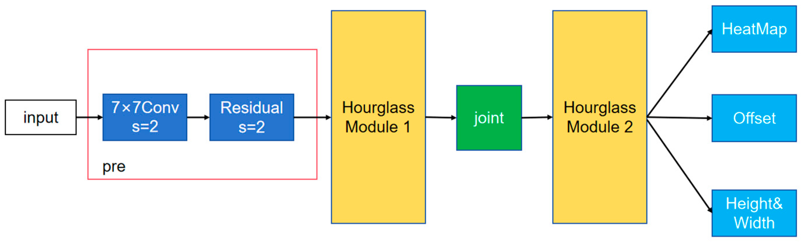
CenterNet detects an object’s position based on the center of the detection box, so it has only one large branch, which contains three small branches. The network structure diagram is shown in
Figure 1. As can be seen from the graph, the input is processed by a 7 × 7 convolution with a step size of 2 and a residual error unit with a step size of 2 to compress the width and height of the image into a quarter of the original. The first hourglass convolutional neural network is followed by a joint connection to the second hourglass convolutional neural network module and a three-branch output at the head. The heatmap branch size is (W/4, H/4, C), and the offset branch size is (W/4, H/4, 2), which is used to refine the heatmap output and improve the location accuracy. The width branch size (W/4, H/4, 2) is used to predict the width and height of the key point-centric detection box. The loss function consists of the sum of the three parts of the output loss.
FCOS is not only an unanchored detector but also a one-stage convolutional neural network (a fully convolutional network, FCN). The network architecture diagram is shown in
Figure 2. The backbone network is Resnet50, and the Feature Pyramid Network (FPN) generates P3, P4, and P5 on the C3, C4, and C5 outputs of the backbone network; then, on the basis of P5, we obtain P6 from a convolution layer with a convolution kernel size of 3 × 3 and a step length of 2; finally, based on P6, P7 is obtained from a convolution layer with a convolution kernel size of 3 × 3 and a step length of 2. The detection head is shared by P3–P7, which is divided into three branches: classification, regression, and IOU (center-ness), where regression and center-ness are two distinct sub-branches on the same branch. As can be seen from the diagram, each branch will first pass through the four composite modules of “convolution layer + normalization layer + activation function layer”; finally, a convolution layer with the size of 3 × 3 step is used to obtain the final prediction result. The colors blue, green, red, orange, and purple in the image represent the head, neck (PAFPN) portion, classification branch, regression branch, center-ness branch, and convolution layers in the head, respectively. For the classification branch, several score parameters of the target detection task category are predicted on each position of the prediction feature map. For the regression branch, four distance parameters are predicted on each position of the prediction feature map, i.e., the distance from the left side of the target, upper side distance, right side distance, and lower side distance; at this point, the predicted values are on the scale of the relative feature map. For the center-ness branch, one parameter center-ness is output at each location of the predicted feature map, which reflects the distance of a point on the feature map to the target center, with a range of 0 to 1. The closer the point is to the target center, the closer the output parameter value is to 1, and the farther the distance is from the target center, the closer the output parameter value is to 0.
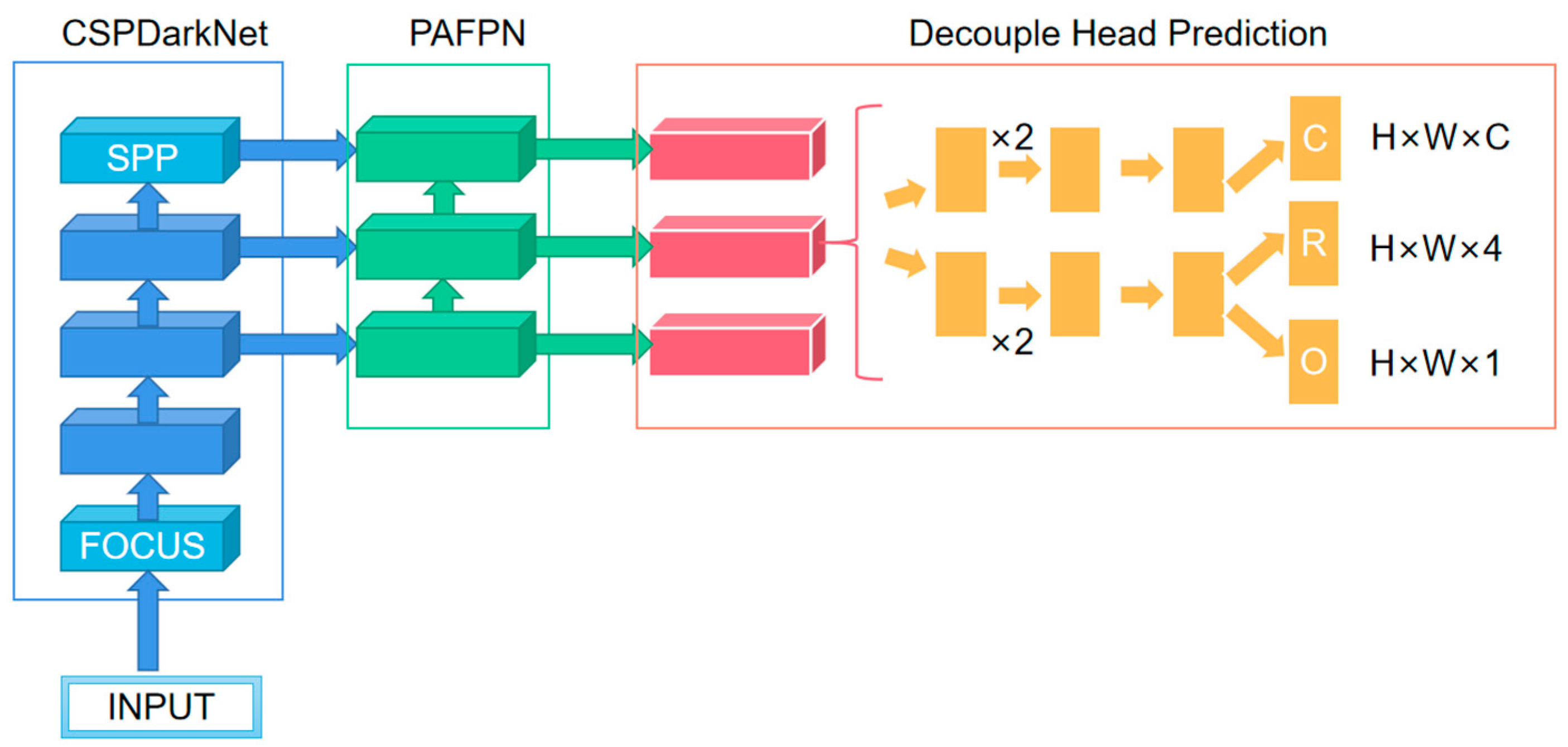
YOLOX is an improvement on YOLOV5, and its structure diagram is shown in
Figure 3. Three of the key innovations are its decoupled head, the fact that it is anchor-free, and its advanced label assigning strategy (SimOTA). Previous probes were implemented using a convolution layer with a convolution core size of 1 × 1 that predicted both category scores, bounding box regression parameters, and object-ness; this approach is called a coupled detection head. The creators of YOLOX think that the coupling detector is harmful to the detection performance of the network; if it is replaced by the decoupling detector, the convergence speed of the network can be greatly improved, and the corresponding experiments can be carried out. The results show that AP can be improved by about 1.1 points by using a decoupling head. Three different branches are used for prediction classification (C), regression (R), and IOU parameters (O) in decoupling heads, but different heads are used for different prediction feature graphs in YOLOX, that is, parameters are not shared. On the surface, the decoupling detector improves the performance and convergence speed of YOLOX, but on a deeper level, it makes it possible to integrate it with the downstream detection tasks.
In the image, blue represents the backbone network, and light blue represents some special modules (FOCUS and SPP) in the base backbone model. The FOCUS structure obtains four independent feature layers by taking a value every other pixel in an image, then the four independent feature layers are stacked; at this point, the width and height information is concentrated on the channel information, and the input channel expanded four times. The SPP structure extracts features by a maximum pool of different pool sizes to improve the receptive field of the network. Green indicates the neck (Pyramid Attention Feature Pyramid Network, PAFPN) section, red indicates the head, orange indicates the convolution layer of the head, C indicates the classification branch, R indicates the regression branch, and O indicates the IOU branch. In H × W × C, C represents the number of target classes detected, 4 represents the target bounding box parameter of network prediction, and 1 represents the object-ness (IOU) parameter.
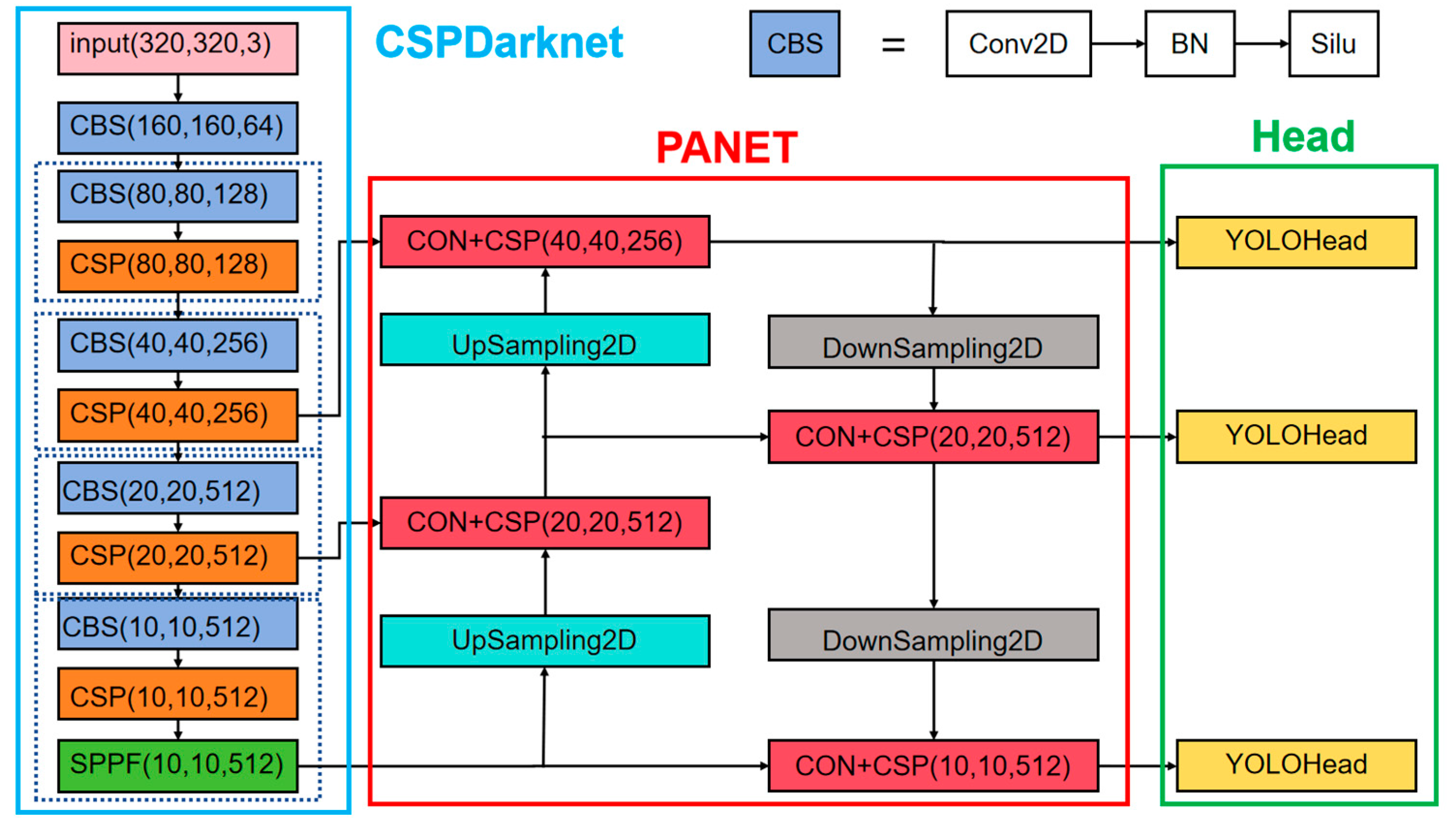
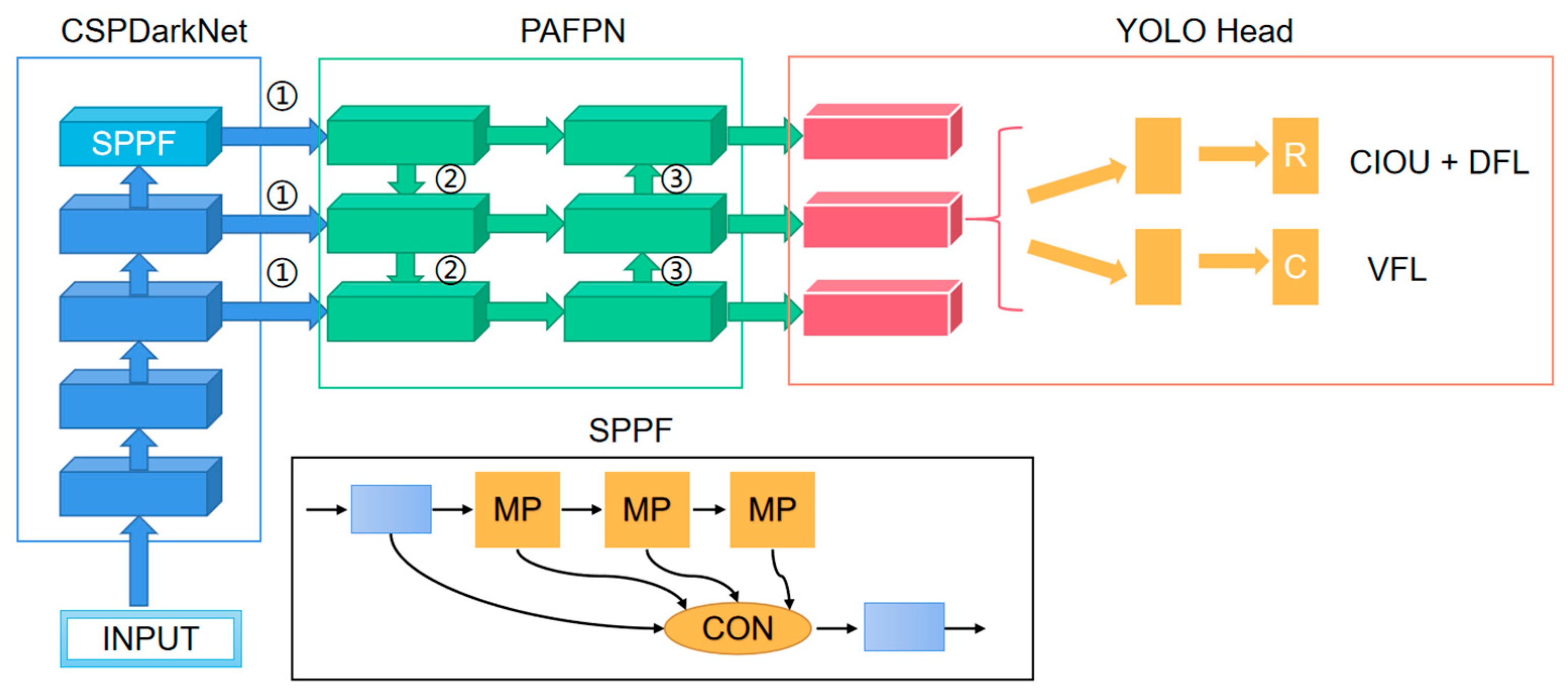
The YOLOV8 network structure and prediction method is similar to the previous YOLO series. It is divided into three parts: the backbone, FPN, and head. The structure diagram is shown in
Figure 4. The backbone is the backbone feature extraction network, which extracts the feature of the input image. The extracted feature layer is the feature set of the input image. Three feature layers are selected for the next step of network construction. FPN is an enhanced feature extraction network, in which three feature layers obtained in the backbone are fused to combine different scales of feature information. Using the path aggregation network (PANET) in YOLOV8, feature fusion is realized not only by up-sampling but also by down-sampling. The head is the network’s classifier and regressor, with the backbone and FPN providing three enhanced feature layers. Each feature layer has a width, height, and number of channels, so the feature map can be regarded as a set of one feature point after another, and each feature point is regarded as an a priori point instead of an a priori frame. Each a priori point has several characteristics of the channel. The head judges the feature point, to determine whether there is an object in the a priori box on the feature point corresponding to it. The detector used by YOLOV8 is decoupled, meaning that classification and regression are not implemented in the same 1 × 1 convolution. Therefore, the work of the whole network can be summarized as follows: feature extraction, feature enhancement, and prediction of objects corresponding to an a priori box.
The backbone feature extraction network makes some optimizations to improve the detection speed: the neck structure uses a 3 × 3 convolution with a normal step size of 2; the CSP module preprocesses two convolutions instead of three convolutions; it also borrows from YOLOV7’s multi-stack architecture. That is, the number of channels of the first convolution is expanded to double the original, and then the result of the convolution is split in half on the channels, which can reduce the number of times of the first convolution and speed up the network.
In the figure, CBS refers to the “Convolution layer + batch layer + activation function layer” module. Con represents a connection operation. UpSampling2D represents the up-sampling operation, DownSampling2D represents the down-sampling operation, YOLOHead represents the detection head of the network, and the three-dimensional vector in parentheses represents the dimension shape of the feature graph of each layer. The light-blue rectangle represents the backbone of the network CSPDarknet, the red rectangle represents the PANET structure of the network neck, and the green rectangle represents the detection decoupling head of the network.
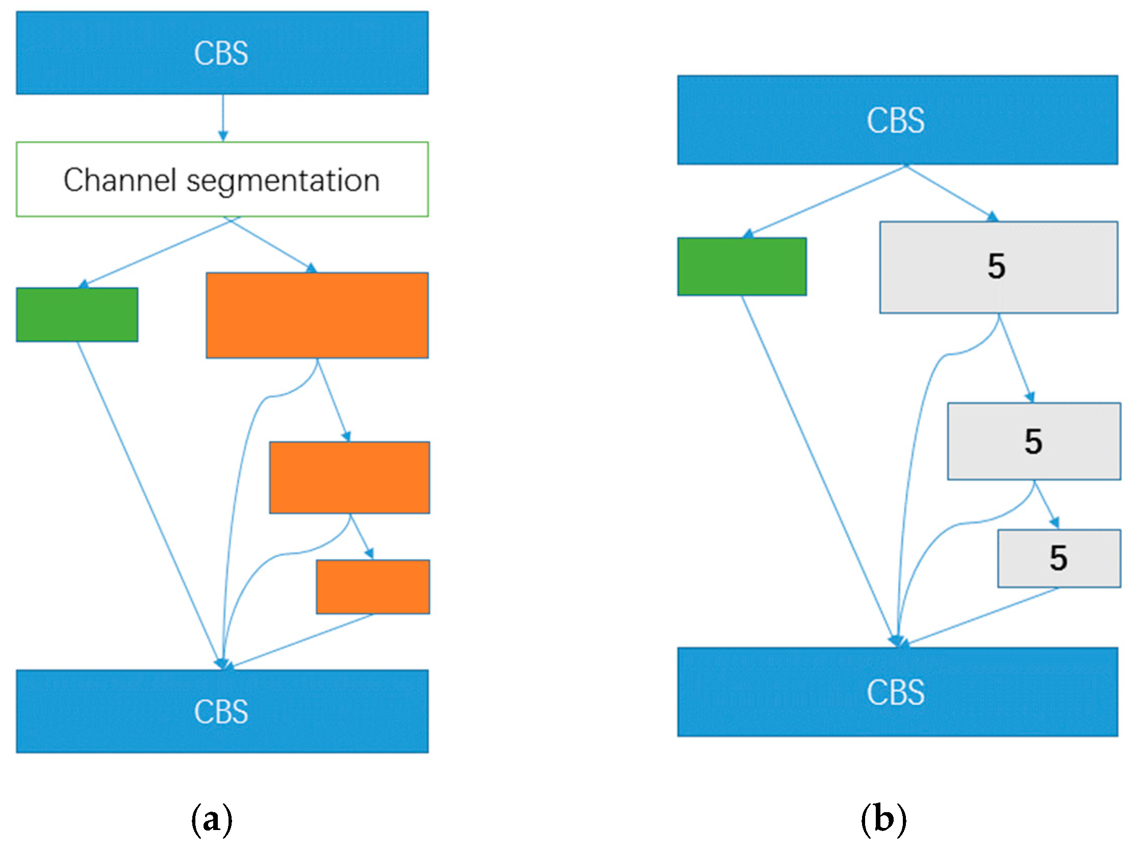
Figure 5 shows the CSP module schematic diagram (a) and the SPPF module schematic diagram (b). The orange represents a bottleneck module, while the green represents no processing. 5 represents the maximum pooling with a kernel size of 5.
The loss of YOLOV8 consists of two parts: (1) The regression part: Since YOLOV8 uses DFL for the final regression prediction, it is necessary to add DFL loss to the regression section. The regression loss for YOLOV8 consists of IOU loss versus DFL loss. The IOU loss is calculated by calculating the coincidence of the predicted box and the true box P and then using 1-p. DFL loss is calculated in a probabilistic way, so using cross-entropy, DFL classifies the regression target as a classification target; taking the upper-left corner of the real box as an example, it generally does not lie on a specific grid point, and its coordinates are not integers (the computational loss is not relative to the real graph, but to the grid graph of each feature layer). If the real box is 6.7, then it is closer to 7 and farther away from 6. Therefore, two cross-entropies can be used, that is, the prediction results with 6 cross-entropy given a lower weight, and the prediction results with 7 cross-entropy given a higher weight. (2) The category section: The cross-entropy loss is calculated as the loss component of the category part according to the category of the true frame and the category of the a priori frame. But the label is not 1 at this time, but rather calculated by the degree of coincidence, that is, by the cost function times the forecast box and the true box of the degree of coincidence divided by the true box corresponding to the maximum value.
3.2. Improved Model
The primary goal of the attention mechanism is to direct the network’s attention toward areas that require greater attention in order to achieve adaptive attention in the system. Broadly speaking, there are three types of attention mechanisms: spatial, channel, and hybrid attention mechanisms. Though location information is crucial for creating spatially selective attention maps, channel attention (e.g., SE attention) has a substantial impact on enhancing model performance. Consequently, unlike channel attention, which combines feature tensors into a single feature vector through two-dimensional global pooling, Coordinate Attention (CA), a network attention mechanism, is utilized in this paper to decompose channel attention into two one-dimensional feature coding processes that aggregate features along two spatial directions. This makes it possible to record precise location information along one spatial direction while capturing remote dependencies along another. After that, the feature map is encoded into two attention maps: one that is location-sensitive and another that is direction-aware. These attention maps can be applied complementarily to the input feature map to improve the representation of objects of interest.
Figure 6 below displays the CA block schematic diagram.
The attention mechanism is a plug-and-play module that can be positioned in a reinforced feature extraction network, behind any feature layer, or behind a backbone network. This paper applies the attention mechanism to the enhanced feature extraction network because the pre-training weights of the network cannot be used when placed on the backbone. At this point, attention modules can be inserted into the network at three different positions: after the reinforcement feature layer (①), after up-sampling and before the connection layer (②), and after down-sampling and before the connection layer (③). The specific insertion network structure diagram is displayed in
Figure 7 below.
In the image, red denotes the head, orange in the red anchor indicates the convolution layers in the head, blue represents the backbone, light blue indicates some special module (SPPF) in the base backbone model, green represents the neck (PAFPN) portion, and R stands for regression branch. The black anchor displays the SPPF detail; the graduated blue indicates the “Batch Normalization + Leaky Relu model + Convolution”; MP stands for Maxpool layer; and CON stands for Concat operate.


