Article

Hydraulic Support Liquid Supply System Adaptive Pump Controlled Pressure Stabilization Control Under Strong Time-Varying Load

by
Chao Cao
1,2,*,
Kai Gao
1,
Hao Wang
1,
Yanzhao Pan
1,
Zhendong Deng
1,
Haoyan Xu
1,
Di Huang
1,
Xinglong Zhao
3 and
Jiyun Zhao
2,*
1
School of Mechatronic Engineering, China University of Mining and Technology, Xuzhou 221116, China
2
National Key Laboratory of Intelligent Mining Equipment Technology, Xuzhou 221116, China
3
State Key Laboratory for Fine Exploration and Intelligent Development of Coal Resources, China University of Mining & Technology, Xuzhou 221116, China
*
Authors to whom correspondence should be addressed.
Processes 2024, 12(12), 2774; https://doi.org/10.3390/pr12122774
Submission received: 6 November 2024 / Revised: 23 November 2024 / Accepted: 3 December 2024 / Published: 5 December 2024

Abstract

:
The hydraulic support liquid supply system provided power for the hydraulic support, serving as the core to ensure safe support of the coal mining face and to maintain continuous, efficient, and stable advancement of the coal mining operations. The hydraulic support faced complex loads while operating on the fully mechanized mining face. To meet the requirement of rapidly following the coal mining machine’s movement, numerous actuators of the hydraulic support frequently performed sequential actions, and the liquid demand of the hydraulic support varied strongly over time, causing the hydraulic system to endure constant pressure and flow shocks, making it difficult to ensure the production efficiency and equipment reliability of comprehensive working face. This study analyzed the pressure and flow characteristics of the liquid supply system during the periodic actions of the hydraulic support. To address the strong time-varying load and liquid demand during the simultaneous actions of the hydraulic support, an Extended State Observer (ESO) was designed for observation and compensation. An Active Disturbance Rejection Control (ADRC) method suitable for the configuration of a rapid pump-controlled liquid replenishment and pressure stabilization system was proposed, and a co-simulation model of the mechanical and control systems was developed by comparing indicators such as the pressure fluctuation amplitude and the execution time of the hydraulic support actions. The pressure stabilization control effects of the ADRC method, the PID control method, and the traditional multi-pump coordinated liquid supply mode under typical time-varying conditions were analyzed and compared. A simulation test system was constructed to validate the results, demonstrating that the ADRC rapid fluid replenishment and pressure stabilization control method can suppress load disturbances, reduce the system pressure fluctuation amplitude by 20.8%, and shorten the hydraulic support operation time by 2.6%.

1. Introduction

The maximum mining height of a fully mechanized mining face in coal mines reaches 10 m, and the working face length extends up to 450 m. The hydraulic support provides a safe space for personnel and equipment on the fully mechanized mining face [1]. A single hydraulic support weighs over 100 t, and the number of hydraulic supports on the working face exceeds 180 units. Numerous hydraulic actuators periodically perform actions such as the sequential pushing action, the pulling frame action, the lifting column action, and the descending column action. The hydraulic support operates using high-pressure emulsion fluid as its power source, supplied by the liquid supply system through pipelines extending over thousands of meters. The hydraulic support liquid supply system reaches a maximum pressure of 42 MPa [2] and a maximum supply flow rate of 5000 L/min [3]. In addition, the hydraulic support typically performs the descending column action, pulling frame action, and lifting column action within 10–15 s [4]. The cylinder diameter of the upright cylinder reaches 500 mm and the cylinder diameter of the push cylinder reaches 200 mm. The flow rate changes can reach thousands of liters in just 3 s. The liquid demand of the actuators exhibits time-varying characteristics, and the geological conditions of the working face are complex, causing the support attitude of the hydraulic support to be affected by the fluctuation of the ground. For example, the loads of the pulling frame action and the sequential pushing action are affected by the change in the ground friction resistance and the weight of the scraper conveyor. The action loads of the lifting column action and the descending column action are affected by the attitude of the hydraulic support itself, which together lead to the strong time-varying load of the hydraulic support actuator. The maximum pressure fluctuation amplitude of the liquid supply system is reduced from 31.5 MPa to 12 MPa in 2 s. The strong pressure and flow shocks inevitably reduce the reliability of the components in the liquid supply system and the hydraulic support. In severe cases, this results in insufficient setting pressure of the hydraulic support, affecting the safe production of the fully mechanized mining face [5].
Many scholars study pressure stabilization control of the hydraulic support liquid supply system to address the frequent pressure shocks present in the system. In terms of the liquid supply system configuration, Mamcic [6] studied the impact of accumulator structural parameters on the dynamic characteristics of the liquid supply system. Van de Ven [7] proposed a new type of hydraulic accumulator, where the piston area varied with the stroke to enhance system pressure stability. Ma [8] and others added accumulators to the existing pump station structure to improve liquid supply system stability, pressure and flow pulsation, and hydraulic shock issues. Li [9] and others optimized pipeline size parameters to improve the transient dynamic characteristics of the pipelines. Shu [10] and Zhao [11] improved the layout of the liquid supply system and pipeline arrangement to reduce pressure transmission losses. Li [12] theoretically analyzed the pressure variation characteristics of the liquid supply system on a working face with multiple hydraulic supports operating simultaneously and optimized the pressure conditions and control sequence for multi-pump coordination. Cao [13] added a booster cylinder circuit in parallel with the hydraulic support leg cylinders, speeding up the system pressure rise rate. In the above studies, adding accumulators to the liquid supply system reduced pressure fluctuations to some extent, but it could not actively regulate them. Moreover, it required dozens of accumulators, increasing the complexity of the pump station configuration and reducing the system’s response speed. Optimizing the pipeline arrangement of the liquid supply system reduced pressure transmission losses but resulted in a more complex pipeline layout.
In terms of control methods, Tian [14] studied the PLC-based variable frequency speed regulation technology for constant pressure and applied it to a multi-pump liquid supply system. Bordeasu [15] used a variable frequency control method for the pump station to continuously adjust the output flow within a certain range. Du [16] employed a PID algorithm to detect pressure changes and control the unloading valve, attempting to maintain pressure near a target value; however, despite favorable simulation results, this approach was not validated in practice. Tan [17] trained an Elman neural network using pressure data from the liquid supply system to implement pressure predictive control for a multi-pump liquid supply system. Li [18] considered parameters such as the coal mining machine’s position, column pressure, and advancement stroke to construct feature vectors and proposed a remote intelligent liquid supply control strategy. Tian [19,20] predicted the running speed of the coal mining machine and calculated the power demand of the hydraulic support based on this speed, subsequently controlling the frequency of the drive motors in the multi-pump liquid supply system to optimize output flow. Peng [21] developed a pump station flow prediction control method based on an online updating Generalized Regression Neural Network (GRNN), which adjusted the optimal flow for stabilized liquid supply during different hydraulic support actions through online learning. Si [22] proposed an immune particle swarm optimization-based fuzzy neural network PID algorithm to improve the control method of the liquid supply system. Although PID algorithms and neural networks were used to adjust the real-time liquid supply flow of the system, theoretically narrowing the difference between the output flow of the liquid supply system and the liquid demand of the hydraulic support actuators, these methods could not overcome the limitations imposed by the inherent characteristics of the liquid supply system, such as the slow response of large-inertia variable frequency emulsion pumps and the small range of flow adjustment. As a result, these methods failed to match the system configuration and adapt to actual working conditions.
In summary, the research findings indicate that there are currently two approaches to achieving pressure stabilization control in the hydraulic support liquid supply system. One approach is to modify the existing liquid supply system structure, and the other is to use algorithms to continuously adjust the output flow of the liquid supply system. Essentially, both approaches aim to accelerate the response speed of the emulsion pump station’s output flow control to quickly match the liquid demand of the hydraulic support, achieving real-time on-demand liquid supply and improving the quality of the liquid supply. However, current research has not considered the impact of the strong time-varying load characteristics present in actual working conditions on system pressure.
Therefore, due to the time-varying characteristics of the liquid demand of the actuator of the hydraulic support liquid supply system, this study adopts the configuration of the rapid pump-controlled fluid replenishment and pressure stabilization liquid supply system to improve the output flow response speed of the liquid supply system and further considers the complex geological conditions of the working face and the strong time-varying load characteristics brought by the attitude of the hydraulic support itself during the action of the actuator. The hydraulic support liquid supply system is simplified into a switch valve-controlled cylinder model, and a strong time-varying observer is designed to suppress the influence of the strong time-varying load on the pressure and accelerate the response speed of the liquid supply system to the strong time-varying liquid demand, thereby improving the pressure control accuracy of the liquid supply system.

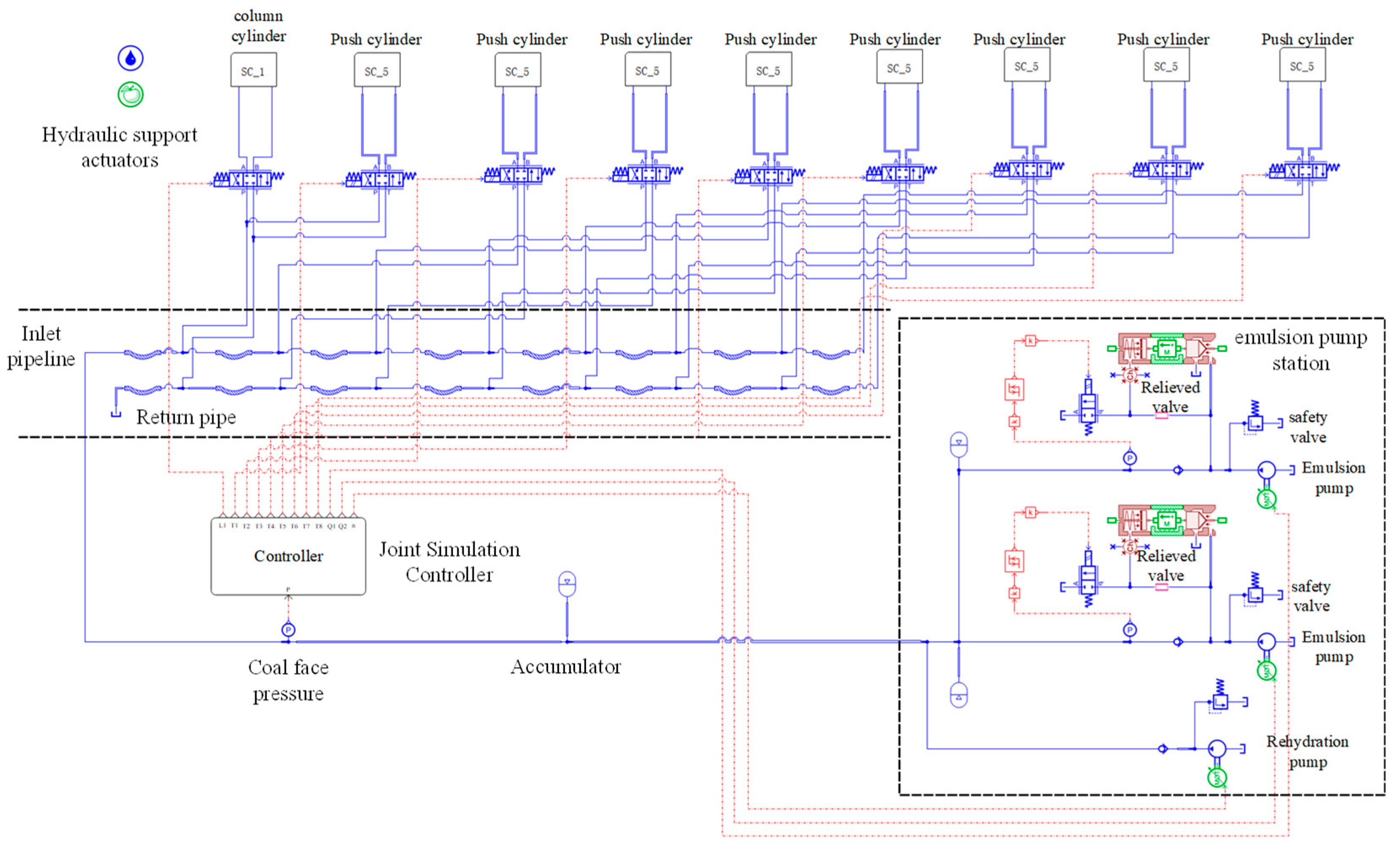
2. Liquid Supply System Configuration and Control Principle

Due to the hydraulic support liquid supply system’s demand for thousands of liters of fluid flow, a multi-pump configuration is used, typically employing the multi-pump linkage configuration or the variable frequency pressure stabilization configuration. The multi-pump linkage configuration [23] consists of several large inertia emulsion pumps, unloading valve groups, and accumulators. By setting the unloading pressures of the valves in stages, it can only achieve stepwise pressure and flow regulation. The variable frequency pressure stabilization configuration [24] builds on the multi-pump linkage setup, using a frequency converter to drive the large inertia emulsion pumps. This enables soft starts of the liquid supply system and a limited range of continuous flow adjustment. However, it suffers from low regulation accuracy and slow response speed, making it difficult for the existing pump station control methods to achieve effective pressure stabilization of the liquid supply system.
Therefore, in this study, the emulsion pump station system configuration adopts the rapid pump-controlled fluid replenishment and pressure stabilization liquid supply system configuration [25], as illustrated in Figure 1. By leveraging the fast response and high control precision characteristics of the high-speed pump combined with a servo motor, the system provides accurate and rapid fluid supply to the working face, ensuring that the fluid flow can promptly meet the operational demands. The replenishment pump employs an Active Disturbance Rejection Control (ADRC) algorithm, using an observer to monitor the strong time-varying load and eliminate the system pressure disturbances caused by these variations.
The principle of the Active Disturbance Rejection Stabilization Control proposed in this study is illustrated in Figure 2. The system uses the pressure values of the liquid supply system at the working face as inputs to the Extended State Observer (ESO). The ESO observes and estimates the total disturbances and pressure-related terms of the system. A PD controller then regulates the flow rate of the replenishment pump, eliminating the interference caused by system disturbances. This allows for rapid and precise control of the pump’s output flow, ensuring that the supply flow from the pump station promptly matches the fluid demand of the actuators. Ultimately, this achieves the goals of reducing the amplitude of system pressure fluctuations, decreasing the frequency of pressure oscillations, and accelerating the operation speed of the hydraulic support.

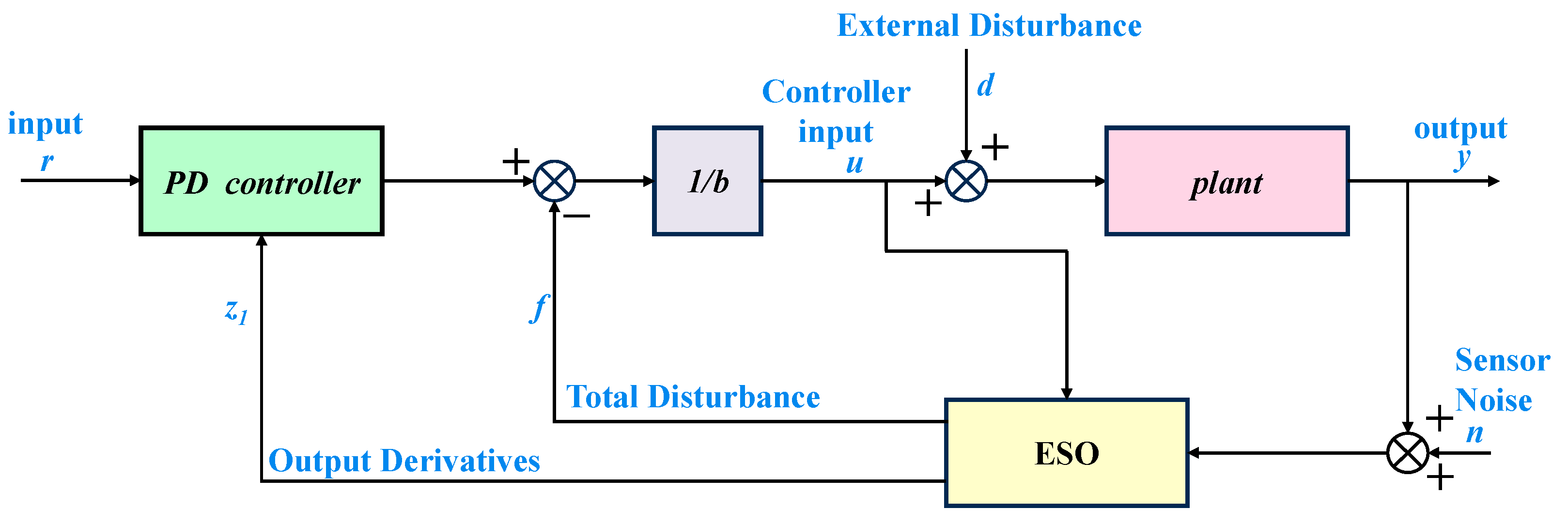
3. Controller Design

This section presents the parameter configuration principles of the pump station system configuration and designs a strong time-varying load observer specifically for the hydraulic support liquid supply system.

3.1. Configure System Configuration Parameters

During the execution of hydraulic support operations, a constant fluid supply flow may cause significant drops or intense fluctuations in system pressure, depending on the specific hydraulic support action. Similarly, for the same hydraulic support action, varying fluid supply flows can lead to different operation speeds of the hydraulic support and changes in system pressure. Therefore, an appropriate fluid supply flow can maintain the system pressure within the range between the unloading and recovery pressures of the unloading valve during the hydraulic support operation, preventing frequent valve opening and closing as well as pressure shocks. This ensures a stabilized fluid supply from the system, with the ideal pressure curve shown in Figure 3 [26].
Based on the characteristics of the ideal pressure curve shown above, the hydraulic support operation process is divided into the accumulator supply phase and the pump station supply phase for analysis. When the hydraulic support actuator starts to operate but the system pressure has not dropped below the unloading valve’s set pressure, it is considered the accumulator supply phase. During this phase, the pump station does not supply fluid; the fluid supply is provided solely by the accumulator and the pre-charged pressurized fluid in the pipeline. The fluid supply flow rate qa during the accumulator supply phase satisfies the following equation [27]:
q a = P u P 0 n P l P 0 n V 0 + p a Δ V g β e
where Pu is the unloading pressure of the unloading valve; Pl is the loading pressure of the unloading valve; P0 is the initial pressure of the accumulator; V0 is the initial volume of the accumulator; pa′ is the rate of change of the pressure curve during the accumulator supply phase; ΔVg is the change in pipeline volume during this process; βe is the bulk modulus of elasticity of the emulsion; and n is the coefficient, taken as 1.4, considering the accumulator supply phase as an adiabatic process.
As the hydraulic support continues to operate until the system pressure reaches the unloading pressure of the unloading valve, the pump station begins to supply fluid to the working face. When the pump station’s fluid supply matches the hydraulic support’s fluid demand in a timely manner, the system pressure rises slowly at a constant rate as the actuators operate. When the actuator operation is complete, the system pressure precisely reaches the unloading pressure of the unloading valve. The stabilized flow qin required to drive the emulsion cylinder during this process is:
q i n = d ( P i n ρ 2 l d f λ ν 2 ρ 2 ξ ν 2 ) d t V β e + A A ( P d P 0 n P u P 0 n V 0 + p a Δ V g β e A A + P A A A P B A B F m ) d t
where Pin is the outlet pressure of the emulsion pump station; ρ is the density of the emulsion; ξ is the local resistance coefficient; v is the fluid velocity; λ is the friction resistance coefficient along the path; l is the length of the pipeline; df is the diameter of the pipeline; PA is the pressure on the inlet side of the hydraulic cylinder; PB is the pressure on the return side of the hydraulic cylinder; AA is the area on the inlet side of the hydraulic cylinder; AB is the area on the return side of the hydraulic cylinder; m is the load mass; and F is the load force.
Therefore, the calculation method for the supply flow qs of the servo pump in the rapid pump-controlled fluid replenishment and pressure stabilization system is:
q s = q immax q r
where qinmax is the maximum flow required for the hydraulic support operation, and qr is the supply flow of the high-flow emulsion pump.

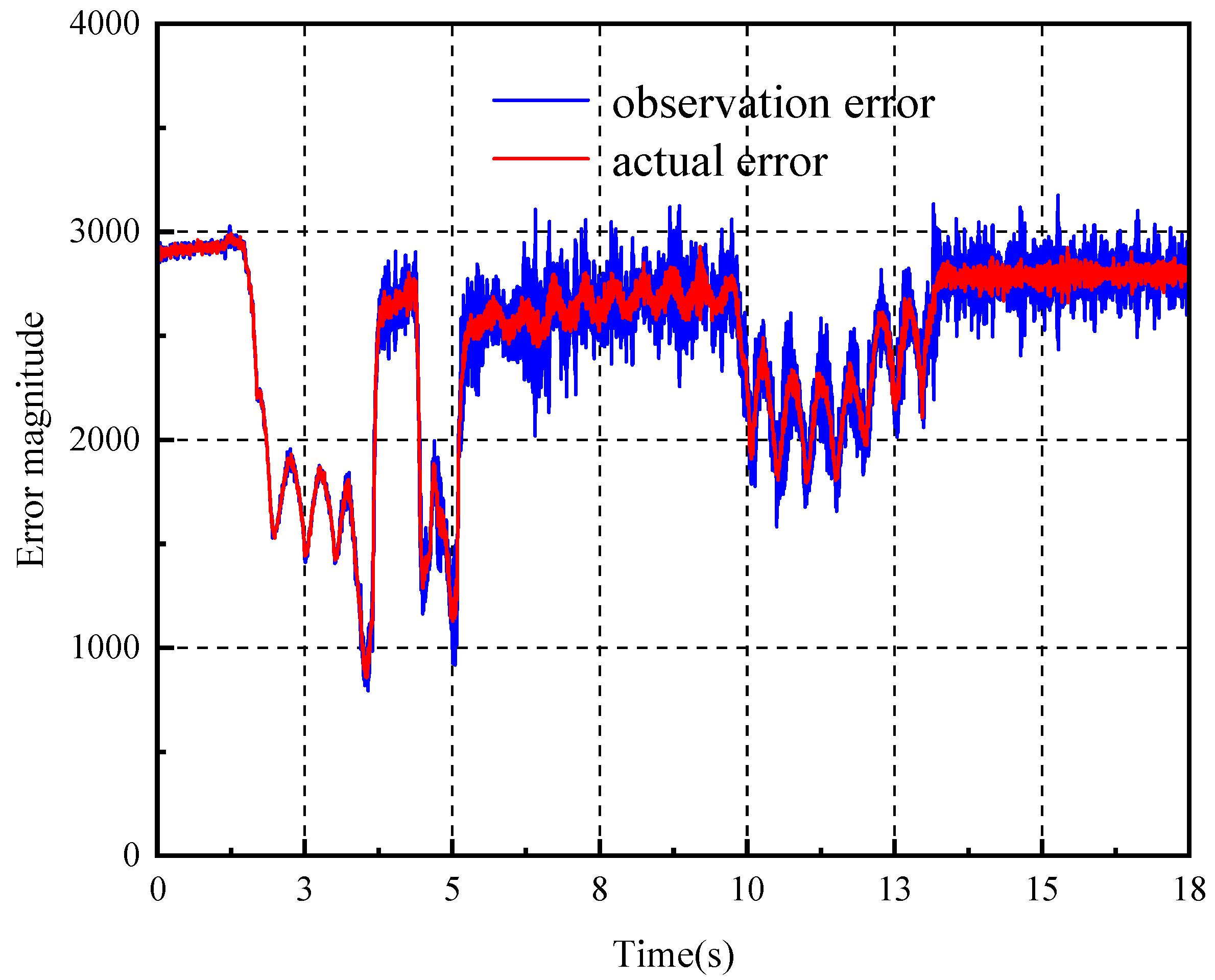
3.2. Extended State Observer Design

The basic actions of the hydraulic support can be categorized into “the descending column action—the pulling frame action—lifting column action” and “the sequential pushing action”. An ESO observer is constructed for each action to reduce the impact of the strong time-varying load from the hydraulic support actuators on system pressure. This improves the control precision and efficiency of pressure stabilization.
The hydraulic support liquid supply system is composed of the emulsion pump station, long pipelines, support directional valves, hydraulic support execution hydraulic cylinders, etc. The support directional valve is an on–off valve, and each hydraulic support execution hydraulic cylinder is controlled by a support directional valve. Different hydraulic support execution hydraulic cylinders have different size strokes, which makes the liquid required by the actuator have strong time-varying characteristics, resulting in a strong time-varying adjustment capability requirement for the response of the liquid supply system. In this study, according to the characteristics of the system components, the different action types of the hydraulic support are simplified to the switch valve control hydraulic cylinder model [28]. The basic equations are as follows:
q L = K q x v K c p L
q 1 = A A d x d t + C i p ( p A p B ) + C e p p A + α 1 d p A d t
q 2 = A B d x d t + C i p ( p A p B ) C e p p B + α 2 d p B d t
where:
α 2 = V o B A B x β e ; α 1 = V o A + A A x β e
From the perspective of power matching of the power transmission mechanism, the load flow qL and load pressure PL are derived, which yields:
p L q L = p A q A p B q B = ( p A q B q A p B ) q A = ( p A A B A A p B ) q A = ( p A n p B ) q A
Therefore, the load pressure PL = PAnPB, and the load flow qL = qA.
p A A A p B A B F l B p d x d t K x f = m t d 2 x d t 2
ps is the supply pressure; q1 is the flow into the hydraulic cylinder; q2 is the flow out of the hydraulic cylinder; pA is the pressure on the inlet side of the hydraulic cylinder; pB is the pressure on the return side of the hydraulic cylinder; AA is the area on the inlet side of the hydraulic cylinder; AB is the area on the return side of the hydraulic cylinder; xv is the valve spool displacement; x is the displacement of the hydraulic cylinder; pL is the load pressure; qL is the load flow; Kq is the flow gain coefficient; Kc is the flow-pressure coefficient; Cip is the internal leakage coefficient of the hydraulic cylinder; Cep is the external leakage coefficient of the hydraulic cylinder; K is the stiffness of the load spring; Bp is the damping coefficient of the piston and load; FL is the external load force; f is the friction force; mt is the equivalent mass of the piston and load; βe is the bulk modulus of elasticity of the emulsion; let AB/AA = n, n ≤ 1.
By combining the above equations, then:
2 q b + 2 q s f α 1 1 + n 3 d p A d t + ( A A + K c 1 ) p A = F l + B p d x d t + K x + f + m t d 2 x d t 2 + A A d x d t + K q x v
where qb is the output flow rate of the emulsion pump station at mains frequency, and qsf is the fluid replenishment control flow rate of the emulsion pump station.
In the above equation, the terms unrelated to pressure pA and the fluid replenishment control flow are defined as the disturbance term h, and the equation simplifies to:
p ˙ A = 1 + n 3 α 1 ( A A + K c 1 ) p A + h 2 ( 1 + n 3 ) α 1 u = d 2 ( 1 + n 3 ) α 1 u = d 2 b u
where u is the output, and d includes any terms unrelated to the control variable.
Define x = x 1 x 2 T = p A d T , then:
x ˙ 1 = d + b u = x 2 + b u x ˙ 2 = d ˙ = m
where m denotes the derivative of d.
According to the standard form of the state-space equation, obtain:
x ˙ 1 x ˙ 2 = 0 1 0 0 x 1 x 2 + b 0 u + 0 1 m y = 1 0 x 1 x 2
Design the observer based on the above equation [29]:
x ^ ˙ = A x ^ + B u + L ( y y ^ ) y ^ = C x ^
Here, A, B, and C are matrix coefficients, L is the observer gain. The coefficients for the observer are determined as:
x ^ ˙ = ( A L C ) x ^ + B L u y A L C = l 1 1 l 2 0 , B = B L = b l 1 0 l 2 , C = 1 0 0 1
Determine the observer bandwidth w0 and the controller bandwidth wc based on the observer design form and use the coefficient assignment method to establish the expressions for l1 and l2.
S I A ^ = s 2 + l 1 s + l 2 = ( s + w 0 ) 2
The extended state observer observes the system’s time-varying load disturbances and a PD controller is used to control the system, where the expressions for kp and kd are also determined using the parameter assignment method.
s 2 + k d s + k p = ( s + w c ) 2
Then: l 1 = 2 w 0 ; l 2 = w 0 2 ; k d = 2 w c ; k p = w c 2 .
The final coefficient matrix is obtained as:
A L C = 2 w 0 1 w 0 2 0 , B = B L = b 2 w 0 0 w 0 2 , C = 1 0 0 1
Thus, by designing an extended state observer, the system observes the strong time-varying load disturbances of the liquid supply system. The observer cancels out the disturbance component in the control signal, effectively reducing the liquid supply system to a pure integrator. A PD controller then controls the output flow of the liquid supply system, ultimately achieving pressure stabilization.

4. Control Characteristic Analysis

This section analyzes the pressure stabilization control effects of different control methods through co-simulation using AMESim2021/Simulink R2016b and simulation of the periodic operations of the hydraulic support.

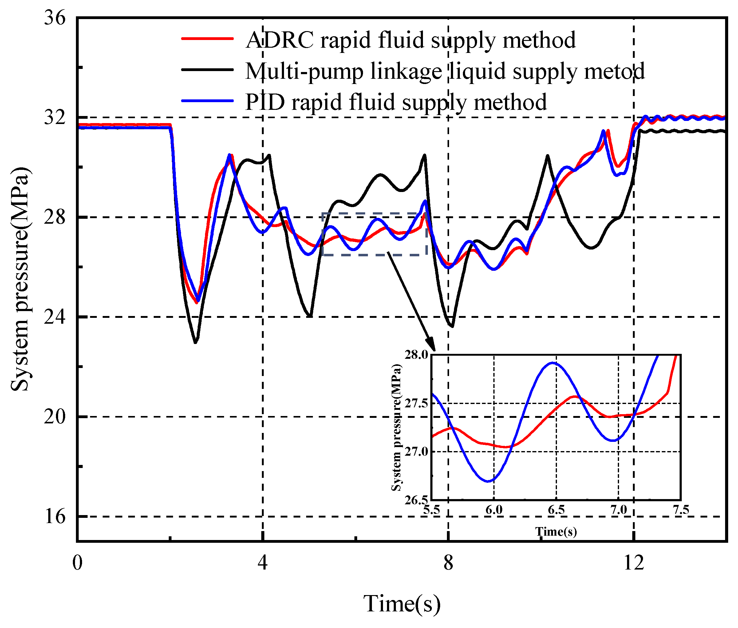
4.1. Simulation Design

The basic operations of the hydraulic support include the descending column, pulling frame, lifting column, and sequential pushing action [30]. Furthermore, due to the characteristic of the hydraulic support’s actual periodic operations where “descending column, pulling frame, lifting column” and “the sequential pushing action” are performed simultaneously [31], the operations in this study are designed to execute these actions in parallel.
The simulation parameters are set based on the specifications of the ZY12,000-28-64D hydraulic support used for a 6.4 m large mining height face. This hydraulic support features double telescopic legs, with each leg weighing 2875 kg and having a rated working resistance of 6000 kN. The pushing cylinder has an inner diameter of 200 mm, a piston rod diameter of 140 mm, and a stroke length of 960 mm, providing an advancing force of 601 kN and a retracting force of 1178 kN. Other system-related parameters are set as shown in Table 1.
The co-simulation model, as shown in Figure 4, mainly consists of the emulsion pump station, supply and return pipelines, hydraulic support directional valve, hydraulic support, and the co-simulation controller. The pump station configuration uses a rapid pump-controlled fluid replenishment and pressure stabilization system. The maximum supply flow rate of the replenishment pump is determined based on the pressure stabilization flow calculation method. The stabilized flow rate is 342 L/min for the descending column action, 611 L/min for the pulling frame action, 1132 L/min for the lifting column action, and 1011 L/min for the sequential pushing action. Considering the simultaneous operation characteristics of the hydraulic support, the maximum supply flow rate of the replenishment pump is set to 553 L/min.
Based on the simultaneous operation characteristics of the hydraulic support, the simulation is designed so that a single hydraulic support performs “the descending column action- the pulling frame action- lifting column action” simultaneously with eight hydraulic supports performing the sequential pushing action. The corresponding action loads are simulated using a constant value plus a sine function to represent the strong time-varying characteristics of the liquid supply system load. According to the technical parameter manual of ZY12,000-28-64D hydraulic support, the weight of the column cylinder is 2875 Kg. In the process of lifting the column, the load force of the column comes from the self-weight M of the column and the friction f between the piston rod of the column emulsion cylinder and the inner cavity of the cylinder. It is also affected by the attitude of the hydraulic support itself. The load force of the lifting column is Fs = (Mg + f)k1, where k1 is the coefficient, which is affected by the attitude of the hydraulic support. In the process of descending the column, the column is subjected to the pressure of the roof and its own friction. The load force of the column is Fj = Fd + f, where Fd is the pressure of the roof on the hydraulic support. The load force in the process of the pulling frame action and the sequential pushing action is referenced by the hydraulic support parameter manual. The pushing force of the pushing cylinder is 601 KN, and the pulling force is 1178 KN. Consequently, the load for the descending column is set to 140 + 14sin(2πt) kN, the load for pulling the frame is set to 1178 + 117sin(2πt) kN, the load for lifting the column is set to 1100 + 110sin(2πt) kN, and the load for the sequential pushing action is set to 601 + 60sin(2πt) kN.
The multi-pump linkage supply method uses two high-flow emulsion pumps, each with a capacity of 400 L/min, employing a staged unloading approach to supply fluid to the working face. The PID rapid fluid replenishment supply method uses two 400 L/min high-flow emulsion pumps and one 532 L/min replenishment pump to supply fluid to the working face. The co-simulation controller contains three PID controllers with different parameters, each corresponding to one of the hydraulic support actions—descending the column, pulling the frame, and lifting the column—executed simultaneously with the sequential pushing action, providing differential fluid supply based on the specific action of the hydraulic support. The ADRC rapid fluid replenishment supply method uses two 400 L/min high-flow emulsion pumps and one 532 L/min replenishment pump to supply fluid to the working face. The co-simulation controller consists of an Extended State Observer (ESO) and a PD controller. The ESO observes and estimates the total system disturbances and pressure-related terms, and the PD controller then regulates the flow of the replenishment pump to eliminate the disturbances caused by the system.

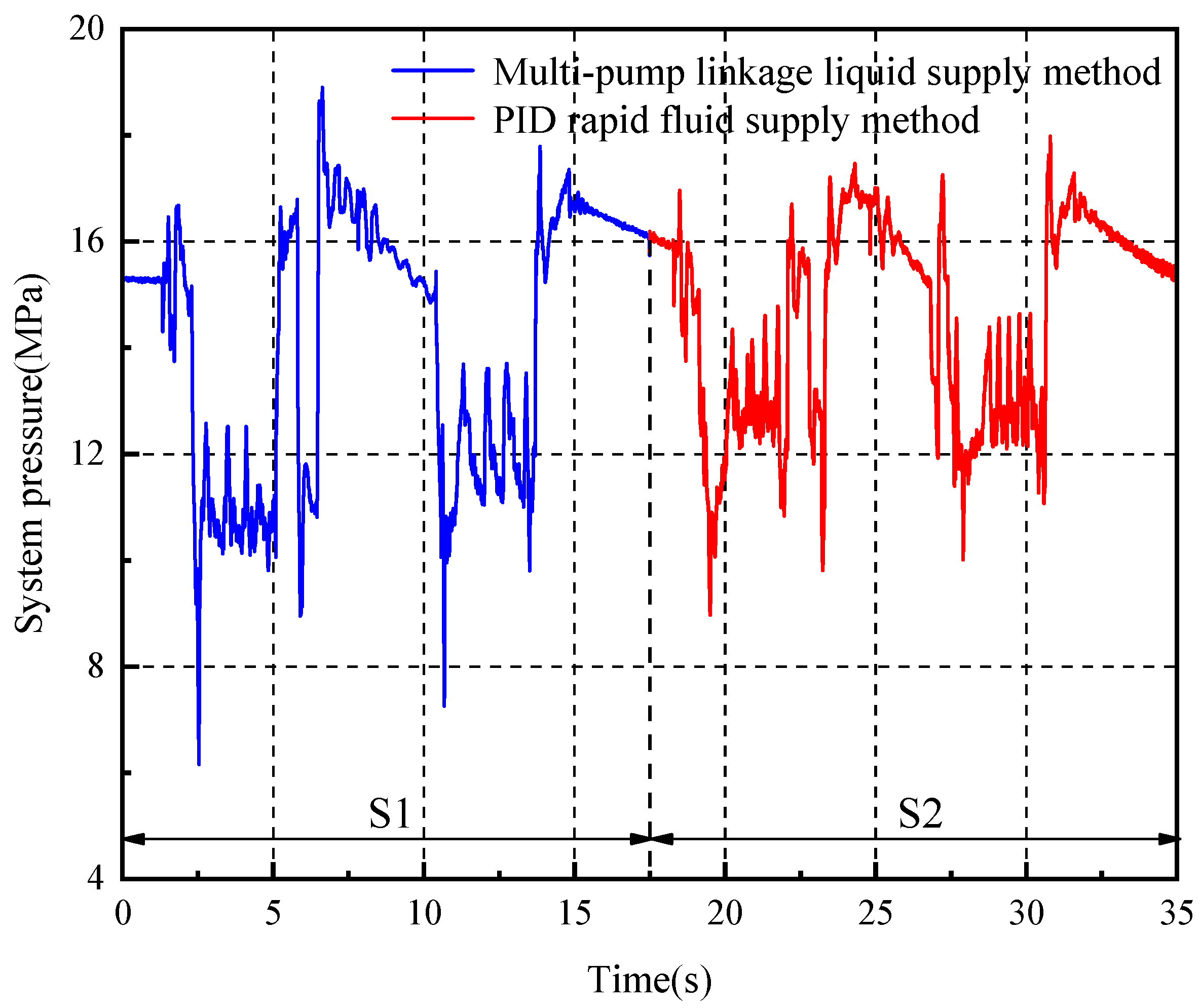
4.2. Simulation Result

First, a comparative analysis of the actual error curve and the observed error curve was conducted, and the values of the observer bandwidth w0 and the controller bandwidth wc were determined using simulation parameters. When b is set to 20, w0 to 130, and wc to 80, the actual and observed error curves are shown in Figure 5. The average amplitude difference between the observed error and the actual error is 7.5%, with the frequencies being consistent. The stability is good, and there is no phase lag, enabling accurate observation of the strong time-varying load.
The pressure curves of the liquid supply system under the multi-pump linkage supply method, the PID rapid fluid replenishment method, and the ADRC rapid fluid replenishment method are compared, as shown in Figure 6.
As seen in Figure 6, the ADRC rapid fluid replenishment method significantly reduces the pressure fluctuations of the entire liquid supply system compared to the PID rapid fluid replenishment method, compensating for the impact of the strong time-varying load on pressure stabilization. The maximum amplitude of pressure fluctuations in the multi-pump linkage supply method is 8.65 MPa, with the unloading valve opening and closing four times during the hydraulic support’s periodic operations, and the operation execution time is 10.14 s. The PID rapid fluid replenishment method has a maximum pressure fluctuation amplitude of 6.87 MPa, with the unloading valve opening and closing three times, and the operation execution time is 10.02 s. The ADRC rapid fluid replenishment method achieves a maximum pressure fluctuation amplitude of 6.85 MPa, with the unloading valve opening and closing three times, and the operation execution time is 9.92 s.
From the above, it can be concluded that both the PID and ADRC rapid fluid replenishment methods offer optimization in terms of pressure fluctuation amplitude, the number of unloading valve activations, and operation execution time throughout the hydraulic support’s periodic actions. Moreover, the ADRC rapid fluid replenishment method is capable of suppressing pressure fluctuations caused by strong time-varying loads.

5. Experiment

This section further analyzes the simulation and experimental results, comparing the pressure stabilization effects and anti-disturbance performance under strong time-varying loads of the multi-pump linkage control method, the PID rapid fluid replenishment control method, and the ADRC rapid fluid replenishment control method.

5.1. Design of Experiment

To further verify the pressure stabilization effect of the differential pump-controlled fluid replenishment method, a pressure stabilization control experiment is conducted using the hydraulic support fluid supply characteristic test bench, as shown in Figure 7. The test bench’s driving section consists of a variable frequency pump, a replenishment pump, hydraulic support directional valves, high-pressure hoses, and push/leg emulsion cylinders to simulate the liquid supply system of the working face. The loading system, comprising loading cylinders and proportional relief valves, is used to simulate the underground load conditions. A Simulink Real-time monitoring and control system is constructed using hardware such as an industrial computer and data acquisition cards for data collection and system control.
Based on the characteristics of the hydraulic support’s periodic operations and the configuration of the test bench, the experimental actions are designed as follows: ① The push emulsion cylinder extends for 1 s; ② The leg emulsion cylinder extends for 2.5 s, followed by the push emulsion cylinder extending for 1 s; ③ The push emulsion cylinder and the leg emulsion cylinder extend simultaneously for 1 s; ④ The leg emulsion cylinder extends for 3 s; ⑤ Both push emulsion cylinders extend simultaneously for 7 s. The specific parameter values for the test bench experiment are set according to Table 2.
According to the pressure stabilization flow calculation method in Section 3.2, the stabilized flow rate for descending the column is 52 L/min; for pulling the frame, it is 77 L/min; for lifting the column, it is 228 L/min; and for the sequential pushing action, it is 235 L/min. The maximum supply flow rate of the replenishment pump is 30 L/min.
The control method for the replenishment pump is the same as in Section 3.1. For the simulated actions on the test bench, time-varying load pressures are set. During the simulated descending column action, the leg loading cylinder is set to a load pressure of 0.5 + 0.1sin(πt) MPa. During the simulated pulling frame action, the retracting loading cylinder is set to a load pressure of 4.08 + 0.4sin(πt) MPa. During the simulated lifting column action, the leg loading cylinder is set to a load pressure of 3.43 + 0.34sin(πt) MPa. During the simulated sequential pushing action, the leg loading cylinder is set to a load pressure of 0.9 + 0.1sin(πt) MPa, and the push loading cylinder is set to a load pressure of 3.56 + 0.35sin(πt) MPa.

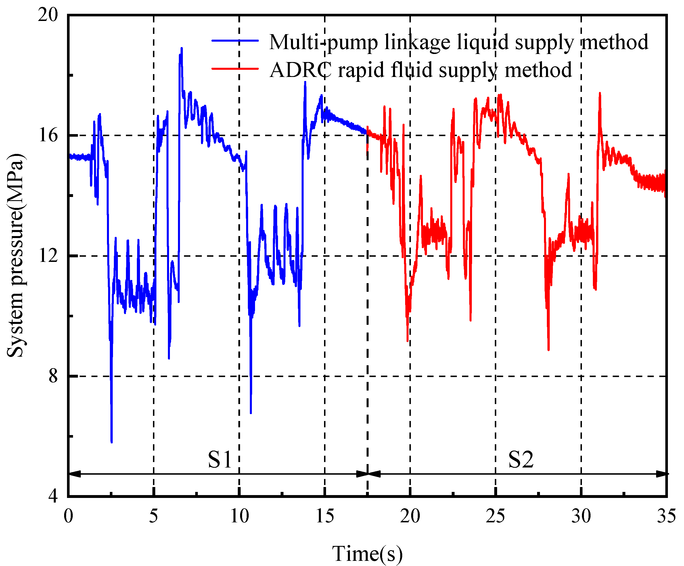
5.2. Experimental Result

First, a comparative analysis of the actual error curve and the observed error curve was conducted. When b is set to 35, w0 to 160, and wc to 120, the actual and observed error curves are shown in Figure 8. The observed error and the actual error differ by a maximum of 33% in amplitude, and the average error is 12%, with the frequencies being basically consistent. The stability is good, and there is no phase lag, allowing for timely tracking of strong time-varying loads.
The pressure curves of the liquid supply system under the multi-pump linkage supply method, the PID rapid fluid replenishment method, and the ADRC rapid fluid replenishment method are compared, as shown in Figure 9 and Figure 10.
Further analysis of Figure 9 and Figure 10 and the data in the table shows that the maximum amplitude of pressure fluctuations in the multi-pump linkage supply method is 9.74 MPa, with the unloading valve opening and closing six times during the hydraulic support’s periodic operations, and the operation execution time is 10.46 s. The PID rapid fluid replenishment method has a maximum pressure fluctuation amplitude of 8.53 MPa, with the unloading valve opening and closing five times, and the operation execution time is 10.24 s. The ADRC rapid fluid replenishment method achieves a maximum pressure fluctuation amplitude of 8.19 MPa, with the unloading valve opening and closing five times, and the operation execution time is 10.19 s.
Throughout the entire hydraulic support periodic operation, compared to the multi-pump linkage supply method, the PID rapid fluid replenishment method reduces the pressure fluctuation amplitude by 12.4%, speeds up the operation execution time by 2.1%, and decreases the number of unloading valve activations by 16.7%. The ADRC rapid fluid replenishment method reduces the pressure fluctuation amplitude by 15.9%, speeds up the operation execution time by 2.6%, and also decreases the number of unloading valve activations by 16.7%. Both the PID and ADRC rapid fluid replenishment methods effectively reduce system pressure fluctuations, accelerate the execution speed of hydraulic support operations, and decrease the frequency of unloading valve activations, improving the matching degree between the pump station’s fluid supply flow and the hydraulic support actuators’ fluid demand. However, the ADRC rapid fluid replenishment method more effectively suppresses the pressure impact caused by strong time-varying loads, offering better pressure stabilization and improving system pressure stability.

6. Conclusions

This study analyzed the pressure–flow relationship of the hydraulic support liquid supply system based on the characteristics of the operating conditions and the actions of the actuators in conjunction with the rapid pump-controlled fluid replenishment and pressure stabilization system configuration. A state-space equation was established for the actions of the hydraulic support actuators and a strong time-varying load observer was designed. The observer estimates the total disturbances and pressure-related terms of the system, and a PD controller is used to regulate the flow of the replenishment pump and eliminate disturbances caused by the system. This ultimately achieves the goal of suppressing pressure fluctuations in the liquid supply system caused by strong time-varying loads. Simulation and experimental comparisons of the pressure stabilization control effects among the multi-pump linkage supply method, the PID rapid fluid replenishment method, and the ADRC rapid fluid replenishment method were conducted. The results verify the pressure regulation and anti-interference effect of the ADRC rapid replenishment liquid supply mode. Follow-up work will further improve the displacement and working speed of the existing pump, improve the rapid and accurate adjustment ability of the output flow of the liquid supply system, and improve the matching speed and accuracy of the outlet flow of the pump station and the liquid demand of the hydraulic support actuator under strong time-varying load.

Author Contributions

Conceptualization, C.C.; Data curation, K.G. and Y.P.; Formal analysis, H.W. and Z.D.; Investigation, K.G.; Methodology, C.C. and K.G.; Software, Y.P., Z.D. and D.H.; Validation, C.C., H.W. and J.Z.; Writing—original draft, K.G., D.H., C.C. and H.X., Writing—review and editing, X.Z.; supervision, J.Z.; funding acquisition, J.Z. All authors have read and agreed to the published version of the manuscript.

Funding

This work was supported by the National Natural Science Foundation of China (52104168), the National Natural Science Foundation of China (U1910212) and the National Natural Science Foundation of China (52105596), the Natural Science Foundation of Jiangsu Province under Grant (BK20210496).

Data Availability Statement

This data is provided upon request due to privacy or ethical restrictions.

Conflicts of Interest

The authors declare no conflicts of interest.

References

  1. Wang, C.; Wang, W.; Guo, Y.; Zhao, D. Multi-condition simulation analysis of a sliding hydraulic support system based on elastoplastic mechanics. Sci. Rep. 2024, 14, 10663. [Google Scholar] [CrossRef] [PubMed]
  2. Zeng, X.; Wang, D. Optimal tracking control of the coal mining face fluid supply system via adaptive dynamic programming. Sci. Rep. 2023, 13, 20002. [Google Scholar] [CrossRef] [PubMed]
  3. Liu, X.; Yang, Z.; Yang, C.P.; Geng, J.G. 1250 L/min high flow high-end intelligent emulsion pump system to assist 10 million tons of coal face in Hongliulin Coal Mine. Intell. Min. 2023, 4, 44–47. [Google Scholar]
  4. Wang, G.F. Hydraulic Support Control Technology, 1st ed.; Beijing University of Aeronautics and Astronautics Press: Beijing, China, 2010; pp. 1–10. [Google Scholar]
  5. Zeng, Q.L.; Xu, W.Q.; Gao, K.D. Measurement Method and Experiment of Hydraulic Support Group Attitude and Straightness Based on Binocular Vision. IEEE Trans. Instrum. Meas. 2023, 72, 7502814. [Google Scholar] [CrossRef]
  6. Mamcic, S.; Bogdevicius, M. Simulation of dynamic processes in hydraulic accumulators. Transport 2010, 25, 215–221. [Google Scholar] [CrossRef]
  7. Van de Ven, J.D. Constant pressure hydraulic energy storage through a variable area piston hydraulic accumulator. Appl. Energy 2013, 105, 262–270. [Google Scholar] [CrossRef]
  8. Ma, Y.; Zhang, D.S.; Zhao, S.; Zhang, S. Research and application of liquid supply system with distributed energy accumulators in fully-mechanized mining face. Coal Sci. Technol. 2024, 52, 238–247. [Google Scholar]
  9. Li, Z.H. Research and analysis on main supply and return system of hydraulic support for large mining height. Mech. Manag. Dev. 2018, 33, 46–48. [Google Scholar]
  10. Shu, F.; Wang, Y.; Li, J. Simulate calcultion about pressure loss in hydraulic pipe system of roof supports. Coal Technol. 2009, 28, 26–28. [Google Scholar]
  11. Zhao, X. Pressure Loss and Dynamic Characteristics of Emulsion Supply and Return Pipeline for Hydraulic Support; Taiyuan University of Science and Technology: Taiyuan, China, 2018. [Google Scholar]
  12. Li, W.; Wei, J. Control strategy for multi-pump emulsion power station in coal mine face. J. Coal Sci. Eng. 2011, 17, 443–446. [Google Scholar] [CrossRef]
  13. Cao, L.; Xu, G.; Su, G.; Cui, J.; Cai, Y.; Cao, H. Design of automatic pressurizing device of hydraulic support initial force. Energy Sci. Eng. 2020, 8, 2868–2877. [Google Scholar] [CrossRef]
  14. Tian, C.; Su, C.; Zhao, W. Application of PLC in Variable Frequency Constant Pressure Control System for Mine Emulsion Pump Station. J. Phys. Conf. Ser. 2021, 1982, 012187. [Google Scholar] [CrossRef]
  15. Bordeasu, D.; Prostean, O.; Filip, I.; Vasar, C. Adaptive Control Strategy for a Pumping System Using a Variable Frequency Drive. Machines 2023, 11, 688. [Google Scholar] [CrossRef]
  16. Du, B.H. Research on Adapt Liquid Supply System of Hydraulic Support Running Double Pumps in Fully Mechanized Mining Face; Taiyuan University of Science and Technology: Taiyuan, China, 2023. [Google Scholar]
  17. Tan, C.; Qi, N.; Zhou, X.; Liu, X.; Yao, X.; Wang, Z.; Si, L. A pressure control method for emulsion pump station based on elman neural network. Comput. Intell. Neurosci. 2015, 2015, 684096. [Google Scholar] [CrossRef] [PubMed]
  18. Li, R.; Wei, W.S.; Lai, Y.H. Long-distance intelligent liquid supply for coal mining faces based on liquid demand prediction. J. Phys. Conf. Ser. 2023, 2561, 012018. [Google Scholar] [CrossRef]
  19. Tian, C.; Wei, X.W.; Zheng, Y. The intelligent control of emulsion pump station. J. Phys. Conf. Ser. 2021, 1881, 022044. [Google Scholar] [CrossRef]
  20. Tian, C.; Wei, X.W.; Yang, C.; Su, C. Optimization Technology of frequency conversion constant pressure control system of mine emulsion pump station in electrical engineering and automation Specialty. Adv. Civ. Eng. 2021, 2021, 5569994. [Google Scholar] [CrossRef]
  21. Peng, Y.; Kou, Z.; Wu, J.; Luo, J.; Liu, H.; Zhang, B. Research on a Pressure Control Method for a Liquid Supply System Based on Online Updating of a Radial Basis Function Neural Network. Processes 2023, 12, 57. [Google Scholar] [CrossRef]
  22. Si, M.; Wu, B.; Wang, Z. Research on large flow intelligent liquid supply system in fully mechanized working face. Mine Autom. 2022, 48, 66–72. [Google Scholar]
  23. Wang, G.F.; Zhang, L.; Li, S.B.; Li, S.; Feng, Y.H.; Meng, L.Y.; Nan, B.F.; Du, M.; Fu, Z.; Li, R.; et al. Progresses in theory and technological development of unmanned smart mining system. J. China Coal Soc. 2023, 48, 34–53. [Google Scholar]
  24. Zhang, W.Q. Research on Intelligent Linkage Control between Frequency Conversion and Electromagnetic Unloading of Emulsion Pump. Coal Mine Mach. 2013, 34, 196–198. [Google Scholar]
  25. Cao, C.; Zhao, J.; Gao, K.; Wang, H.; Li, R.; Liu, H.; Zhang, H. Rapid Pump-controlled Replenishment Pressure-stabilizing Method of the Hydraulic Support Fluid Supply System. Coal Sci. Technol. 2024, 1–12. Available online: http://kns.cnki.net/kcms/detail/11.2402.TD.20240613.1528.007.html (accessed on 23 November 2024).
  26. Fu, X.; Wang, R.F.; Zhao, Y.S. Simulation of hydraulic system of working face support and Research on stabilized pressure fluid supply technology. J. China Coal Soc. 2018, 43, 1471–1478. [Google Scholar]
  27. Zeng, X.T.; Wang, D.L. Analysis of the Influence of Accumulator Configuration on Stable Liquid Supply. Int. J. Simul. Model. 2023, 1, 52–63. [Google Scholar] [CrossRef]
  28. Wang, Y.; Zhao, J.; Zhang, H.; Wang, H.; Wang, J. An Output Cooperative Controller for a Hydraulic Support Multi-Cylinder System Based on Neural Network Compensation. Mathematics 2024, 12, 1866. [Google Scholar] [CrossRef]
  29. Abhilash, P.; Spandan, R.; Simone, B. Wide-Area Damping Control Resilience Towards Cyber-Attacks: A Dynamic Loop Approach. IEEE Trans. Smart Grid 2021, 12, 3438–3447. [Google Scholar]
  30. Xie, B.; Yang, Y. Study on Working Characteristics of 4-Column Hydraulic Support in Lifting–Lowering–Moving State Based on Microcontact Theory and Rigid–Flexible–Mechanical–Hydraulic Coupling Simulation. Actuators 2024, 13, 193. [Google Scholar] [CrossRef]
  31. Ren, B.; Ding, K.; Wang, L.; Wang, S.; Jiang, C.; Guo, J. Research on an Intelligent Mining Complete System of a Fully Mechanized Mining Face in Thin Coal Seam. Sensors 2023, 23, 9034. [Google Scholar] [CrossRef]
Figure 1. Hydraulic support liquid supply system configuration schematic diagram.
Processes 12 02774 g001
Figure 2. Active disturbance rejection voltage stabilization control schematic diagram.
Processes 12 02774 g002
Figure 3. Ideal liquid supply flow pressure curve.
Processes 12 02774 g003
Figure 4. Co-simulation diagram of the AMESim and Simulink.
Processes 12 02774 g004
Figure 5. Simulation error comparison curve.
Processes 12 02774 g005
Figure 6. Simulation comparison of liquid supply system pressure.
Processes 12 02774 g006
Figure 7. Hydraulic support liquid supply system characteristics test bench.
Processes 12 02774 g007
Figure 8. Test error comparison curve.
Processes 12 02774 g008
Figure 9. Comparison of voltage stabilizing effect of PID test results.
Processes 12 02774 g009
Figure 10. Comparison of voltage stabilizing effect of ADRC test results.
Processes 12 02774 g010
Table 1. Simulation parameter table.
Parameter NameParameter Value
Emulsion bulk modulus1900 MPa
The first emulsion pump flow400 L/min
The first emulsion unloading valve set pressure31.5–26.5 MPa
The second emulsion pump flow400 L/min
The second emulsion unloading valve set pressure30.5–25.5 MPa
Gas volume of accumulator18.4 L
Pipe diameter65 mm
Table 2. Test parameter table.
Parameter NameParameter Value
Emulsion bulk modulus1900 MPa
The first emulsion pump flow125 L/min
The first emulsion unloading valve set pressure17–15 MPa
The second emulsion pump flow80 L/min
The second emulsion unloading valve set pressure16–13 MPa
Gas volume of accumulator18 L
Disclaimer/Publisher’s Note: The statements, opinions and data contained in all publications are solely those of the individual author(s) and contributor(s) and not of MDPI and/or the editor(s). MDPI and/or the editor(s) disclaim responsibility for any injury to people or property resulting from any ideas, methods, instructions or products referred to in the content.

