1. Introduction
Since the Swiss-roll combustor (SWR) was first proposed by Weinberg and Lloyd [
1,
2], it has attracted the attention of many researchers as a promising device with which to implement efficient high-temperature combustion on a micro scale with flame stabilization [
3]. This is used for the oxidation of volatile organic compounds (pollutants) in air [
4] and for the partial oxidation conversion of hydrocarbons into syngas [
5,
6,
7].
The SWR configuration provides the means to preheat the initial mixture to the heat of high-temperature combustion products, increasing the total enthalpy of the initial mixture. As such, the concept of excess enthalpy has been implemented in the design of various devices to improve flame stability limits, increase the combustion chamber’s heat capacity, reduce exhaust emissions, etc. The increase in the combustion temperature due to heat recovery provides a possibility to increase the combustion rate and also to use fairly lean mixtures (with an fuel-to-oxidant equivalence ratio of less than 0.3) [
8].
In [
9], the combustion was experimentally investigated in a series of miniature Swiss-roll combustors. It was found that a change in the material of the combustor significantly affected the flame stabilization compared to the effects of a scale-down design. In [
10], the authors carried out experimental and numerical investigations on non-premixed CH4/air combustion in a miniature Swiss-roll combustor. It was shown that the flame structure is a function of the absolute flow rates of fuel and air, as well as the ratio between them. The authors observed six flame patterns: a single flame, twin flames, a pulsating flame, an obviously asymmetric flame, extinction, and blow-off. Vijayan and Gupta, in [
11], successfully demonstrated the stable self-sustained combustion of a premixed propane–air flame at high mean flow velocities in a meso-scale combustor. Ronney and co-workers [
12] developed an SWR-type reformer for the thermal partial oxidation of hydrocarbon fuels (propane, n-heptane, JP-8) into hydrogen-rich syngas for subsequent use in a solid oxide fuel cell for power generation. The reformer was a countercurrent heat exchanger that efficiently recuperated heat from a hot reformate stream generated internally to the reformer and preheated the cold reactants entering the device. Superadiabatic temperatures were achieved without catalysts and external energy sources due to effective heat recuperation. In [
13], the authors fabricated and tested one-turn Swiss-roll combustors made of different materials (Al, Cu, brass, and stainless steel) with fixed channel dimensions, performed the combustion of liquefied petroleum gas and air, and successfully obtained a continuous stable flame at the center of the combustor during all the experiments conducted. Higher heat content values were observed for stainless-steel combustors and lower values were observed for brass.
All those applications rely on the basic distinctive feature of SWRs, namely, highly efficient heat recuperation from the products to the reacting gas and a substantial reduction in heat loss to the environment (in its toroidal version [
14], there is near-perfect elimination).
The process within an SWR depends on a variety of control parameters and the design of the combustor. These are the flow rate of the fluid media, the composition of the reactant gas, the geometry of the combustor, the fluid dynamics coupled with the heat and mass transfer within inflow and outflow branches of SWRs, the chemical kinetics of the gas phase, and solid surface reactions, to mention the most important. Therefore, multiple studies were devoted to experiments on SWRs and performing modeling operations on these reactors, employing detailed kinetic mechanisms and fluid dynamics to take into account the complex geometry of the reacting gas flow [
9,
15].
To improve the stability of portable Swiss-roll combustors, various approaches were used, such as adding catalysts [
16,
17], adding porous backfill [
18], changing channel geometry [
19], and using a bluff body or flame holder [
20].
Swiss roll combustors are extensively studied for their potential merits and promise, primarily on the micro scale. However, there is still a lack of a comprehensive quantitative description, as well as systematic studies of the combustion characteristics in such devices as a function of design and control parameters, which would provide the possibility to design and control scaled-up SWRs for practical applications. Our work aims to partially fill these gaps.
In this work, we experimentally study the stable combustion range of premixed lean ethanol–air mixtures in a newly designed meso-scale Swiss-roll combustor.
2. A Qualitative Model
Let us consider a simplified model for the combustion of a reactive gas in an SWR. Formulating this model, we make a number of simplifying assumptions, which make the model tractable at the expense of its quantitative accuracy.
First, let us assume that the reactive gas (which includes premixed fuel–air mixtures) reacts in a single Arrhenius-type first–order reaction with a high activation energy. Further, let us suppose that the heat capacity of the gas is constant in temperature and that the same applies for the initial mixture and reaction products. The heat exchange coefficient of the gas flow with the channel walls is also constant and independent of temperature and gas velocity.
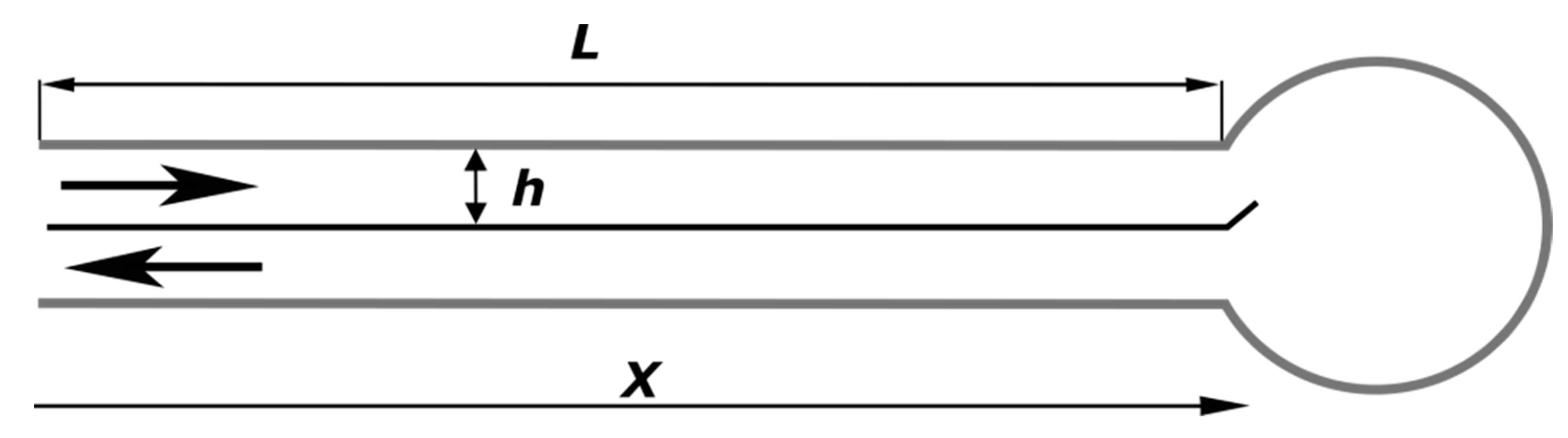
To simplify the geometry of the reactor, let us consider the ‘unwrapped’ roll as presented in
Figure 1, i.e., two channels which are heat-insulated at the exterior that go to and from the central reaction chamber and are separated by a thin wall. The combustion chamber itself can be considered to be an ideal mixing reactor.
Let us consider an established stationary regime of the process.
With the assumptions made, the established stationary process in the combustor is described with the following set of equations. Per unit width in the spiral axis direction, this is described within the inflow channel as follows:
Within the outflow channel, this is described as follows:
where x [m] is the coordinate along the channel; L [m] is the total length of the channel; T [K] is the gas temperature in the inflow channel; t [K] is the temperature in the outflow channel; ρ [kg·m
−3] is the gas density; u [m·s
−1] is the gas velocity; h [m] is the channel width; n [ND] is the dimensionless concentration of the reactant (a deficient component of the mixture); W [kg·m
−3·s
−1] is the reaction rate; k [s
−1] and E [K] are the Arrhenius pre-exponential and activation energy; c [J·kg
−1·K
−1] is the specific heat; q [J·kg
−1] is the specific heat effect of the reaction; β [W·m
−2·K
−1] is the heat exchange coefficient.
In case the gas does not substantially react in the inflow channel as it still has a relatively low temperature and the reaction proceeds mostly to completion within the central reaction chamber (this is particularly true in case when the reactor design involves a catalyst being placed in the chamber), the solution for the problem is straightforward and simple.
Within the combustion chamber, the gas temperature increases by q/c; this value indicates the adiabatic heating in the reaction. Due to the heat exchange with the flow of hot products, the temperature in the inflow channel grows linearly from the initial temperature T(0). The temperature of the gaseous products, respectively, linearly decreases from the maximum value T(0) + q/c + L × q/c × β/(ρcuh), while the temperature difference between the inflow and outflow channels remains constant and the gaseous products leave the combustor when it is heated to the adiabatic reaction temperature. The overheating achieved due to the heat recuperation naturally increases with the total length of the heat exchange spirals, with a higher heat exchange coefficient, and with a lower gas flow rate.
The solution (2) sets no limit on the maximum temperature of combustion with an increasing spiral length; however, one should take into account that, as the gas temperature in the inflow channel increases, the reaction rate in this channel does not become negligible. At some temperature, the heat release rate due to reaction surpasses the heat transferred to the gas due to the heat exchange with the channel wall. Since the activation energy of the reaction is high (this is common in combustion theory), the relation of these two heat flows changes from one where much less heat is released due to the reaction than is obtained from the wall to the opposite, with the heat release due to the reaction becoming much higher, in a very narrow temperature range. This sharp dependence manifests itself as a critical phenomenon, so that reaction remains negligible until the gas is heated to some temperature. Upon reaching this temperature, the reaction accelerates. This occurs in a narrow temperature range, so that one can consider it a critical point, and this critical temperature T* is determined by the reaction heat release rate, which is equal to the heating power associated with the heat exchange of the gas flow with the hot wall.
Then, the temperature pattern within the combustor is as follows:
where L* = (E/ln(hkρc/β) − T(0))/(q/c × β/(ρcuh)) is a critical spiral length corresponding to T(L*) = T*. No further increase in the spiral length would provide a higher combustion temperature.
Note that T* depends on the kinetic parameters of the reaction and its heat exchange properties and does not depend on the gas flow rate. With an increase in the gas flow rate, the critical length increases and for L* ≥ L, the reaction proceeds within the central chamber.
3. Materials and Methods
3.1. Experimental Setup
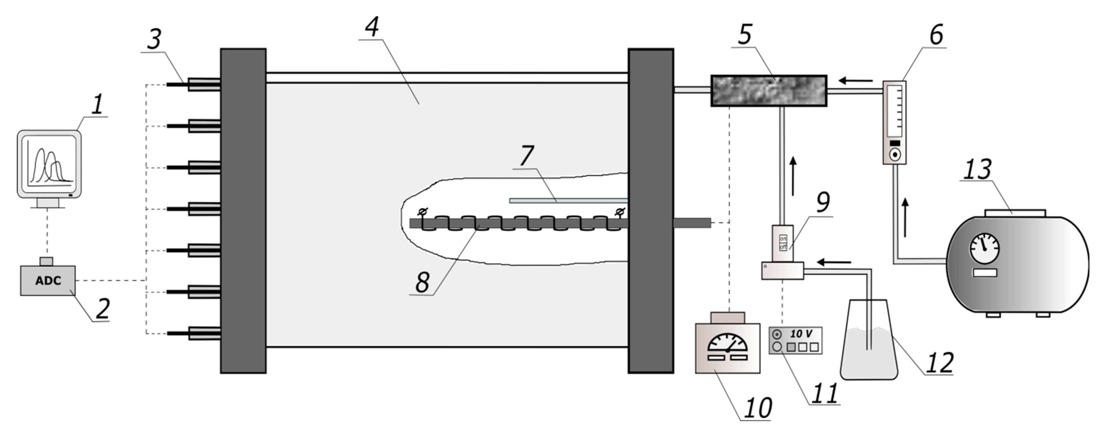
The schematic of the experimental setup is shown in
Figure 2.
The main body of the 5-turn Swiss-roll combustor (4) was made of 0.4 mm thick, 400 mm wide NiCr20AlSi stainless-steel tape. At both sides, the spirals were fixed and sealed with 20 mm layers of phosphate refractory concrete and covered with 50 mm heat insulation plates made of alumina foam. Each of the 3 spiral-shaped channels had the width of 10 mm; thus, the cross-section of each channel was 10 mm by 360 mm. The diameter of the central combustion chamber was 60 mm. One of the channels provided ethanol–air mixture supply. Another one was used to withdraw the gaseous products from the central chamber. The third, outmost channel was passive; it was closed at the outer end and served to provide an air gap for additional heat insulation.
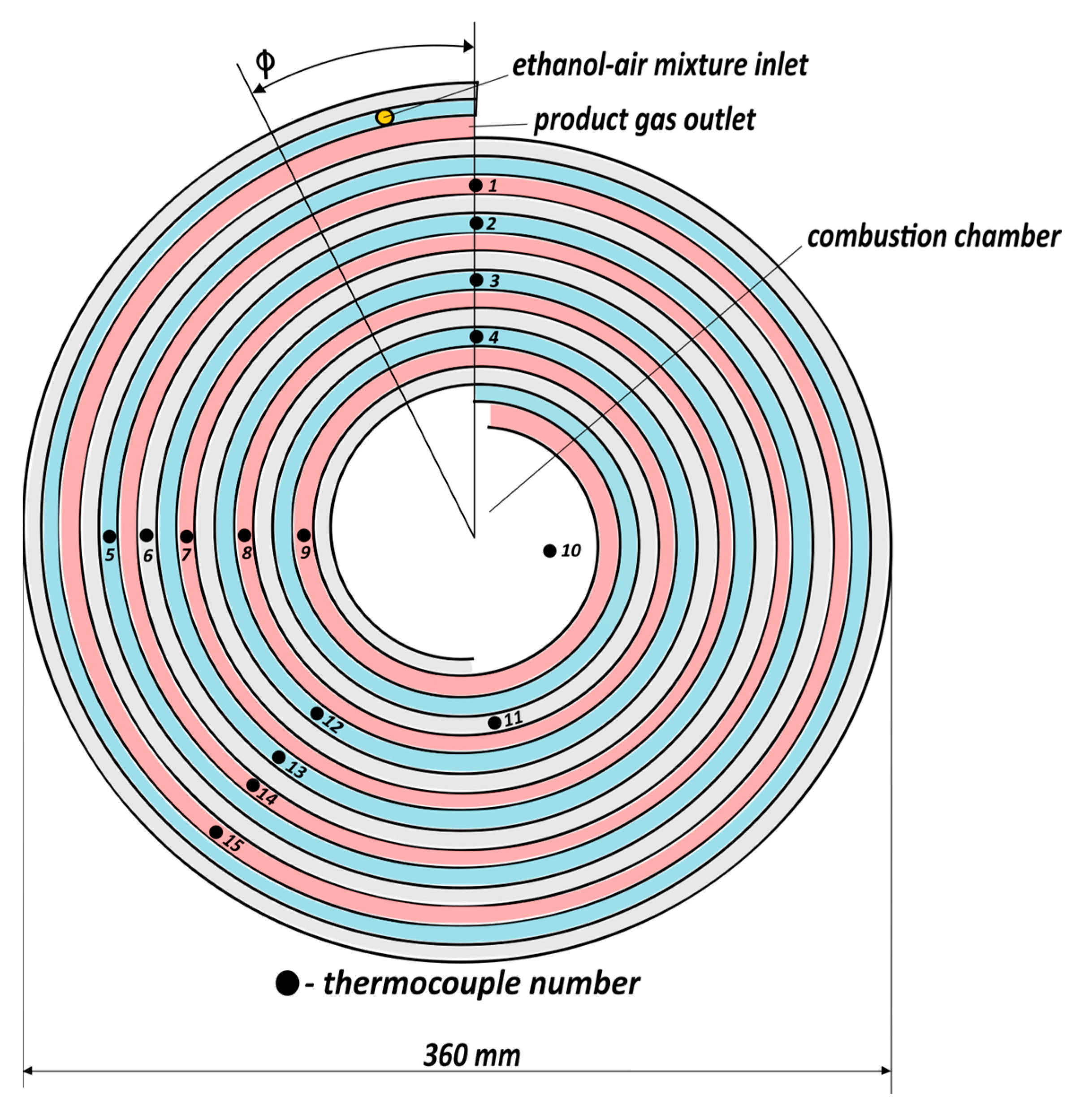
The initial preheating of the combustor was performed by applying voltage to the ignition coil (8) using a laboratory transformer (10). Ethanol drop dosing performed via a fuel supply tube (7) was used to supply ethanol to the combustion chamber during the preheating of the reactor prior to a measurement run. The temperatures in the combustor were measured using fifteen K-type (chromel-alumel) thermocouples (3), positioned as indicated in
Figure 3. The thermocouples were inserted into the respective channels 70 mm deep. The operational range of the thermocouples is −40–+250 °C, with an accuracy 0.05 °C. The thermocouples’ signals were measured using a commercial Zet220 ADC/DAC module (2) with 16 digital inputs. The data acquisition from 15 selected measurement channels was performed using the commercial Zetlab software package (version 28/4/2014); we displayed the current measured parameters on a PC (1) in real time and recorded for further processing. The sampling frequency for all thermocouples was 0.5 Hz.
The ethanol (JSC Rosspirtprom) used in the experiments contained 4% water by mass. Ethanol is a convenient model fuel as it is low-boiling, nontoxic, and readily available. When we investigated the oxygen-excess range, the water in ethanol only made a diluent, which was minor compared to the excess air.
The air flow rate was controlled by means of thermal mass flow meter MV-306 “Bronkhorst” (6); the accuracy was within 2% of the full scale. Ethanol from fuel tank (12) was supplied via a peristaltic pump (9) and its mass flow rate was measured using a fuel pump controller (11); the accuracy was 3%.
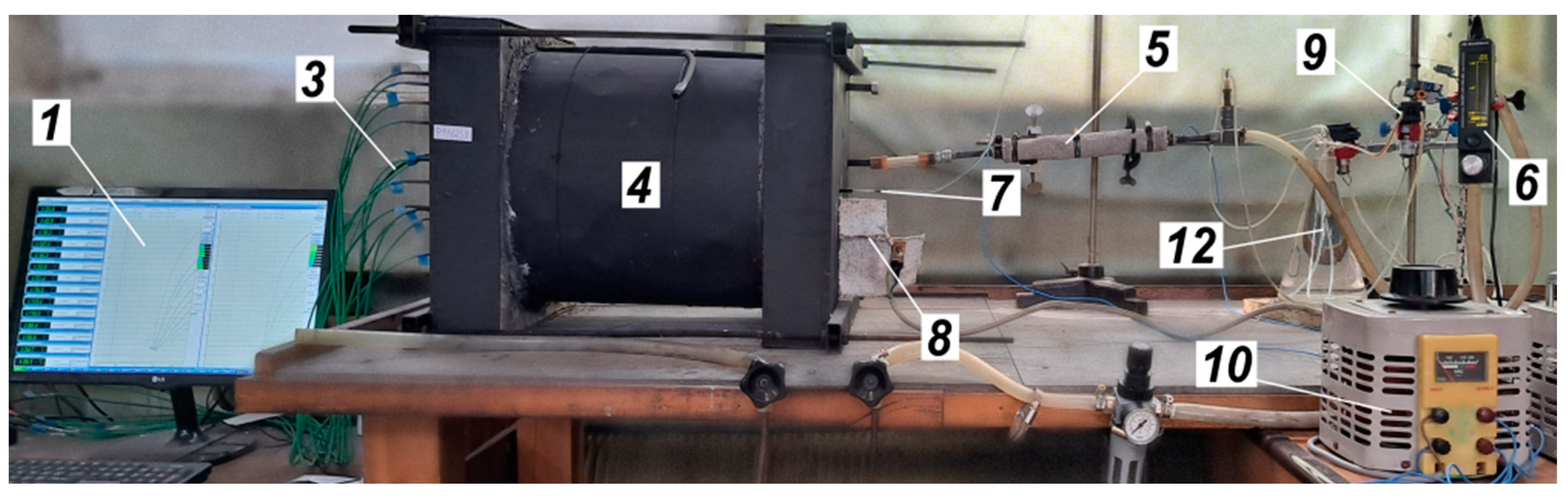
Figure 4 provides a general view of the setup.
3.2. Experimental Procedure
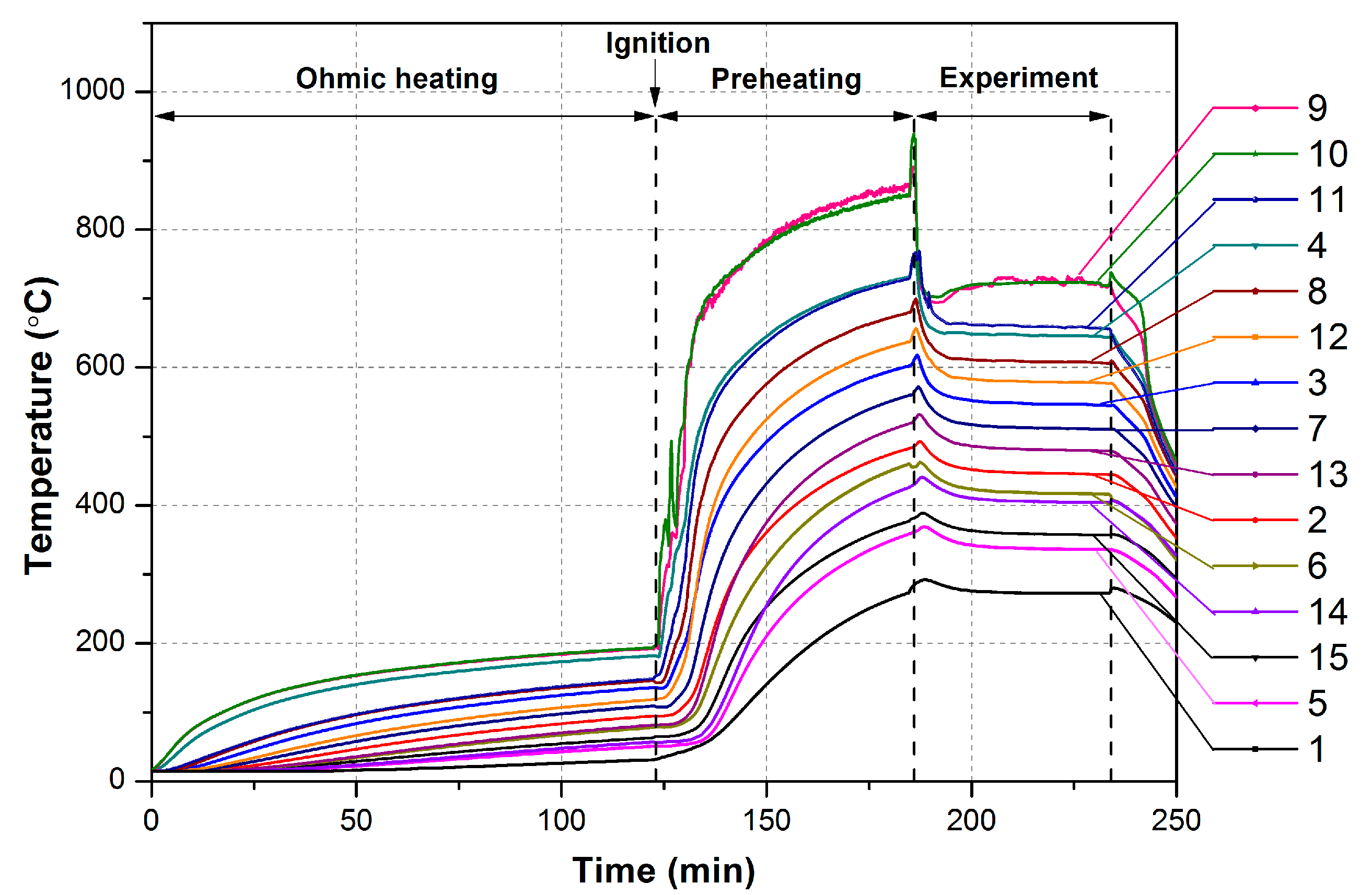
The experimental procedure was as follows. For a start, the voltage was supplied to the ignition coil to preheat the combustion chamber. Once the temperature in the combustion chamber reached ~200 °C, the air flow was supplied to the reactor. Simultaneously, ethanol was supplied to the central combustion chamber and ignited with the ignition coil to provide a flame to preheat the reactor. At temperatures in the center higher 800 °C, the prescribed flow rates of air and ethanol were supplied to an provide ethanol–air mixture. The latter was supplied via an evaporator (5), which is a quartz tube externally heated with an electric heater. The power applied to the heater was controlled to achieve the disappearance of ethanol droplets in the ethanol–air mixture supplied to SWRs. At the same time, the ignition coil was turned off and ethanol drop dosing was stopped. Further, the combustion in the reactor was maintained until the temperature at all thermocouples was constant within ±5 K.
A typical temperature plot for an experimental run is shown in
Figure 5.
Thus, the non-catalytic combustion of the lean ethanol–air mixture in Swiss-roll combustor was arranged. All experimental results refer to the established temperatures of all thermocouples.
4. Results and Discussion
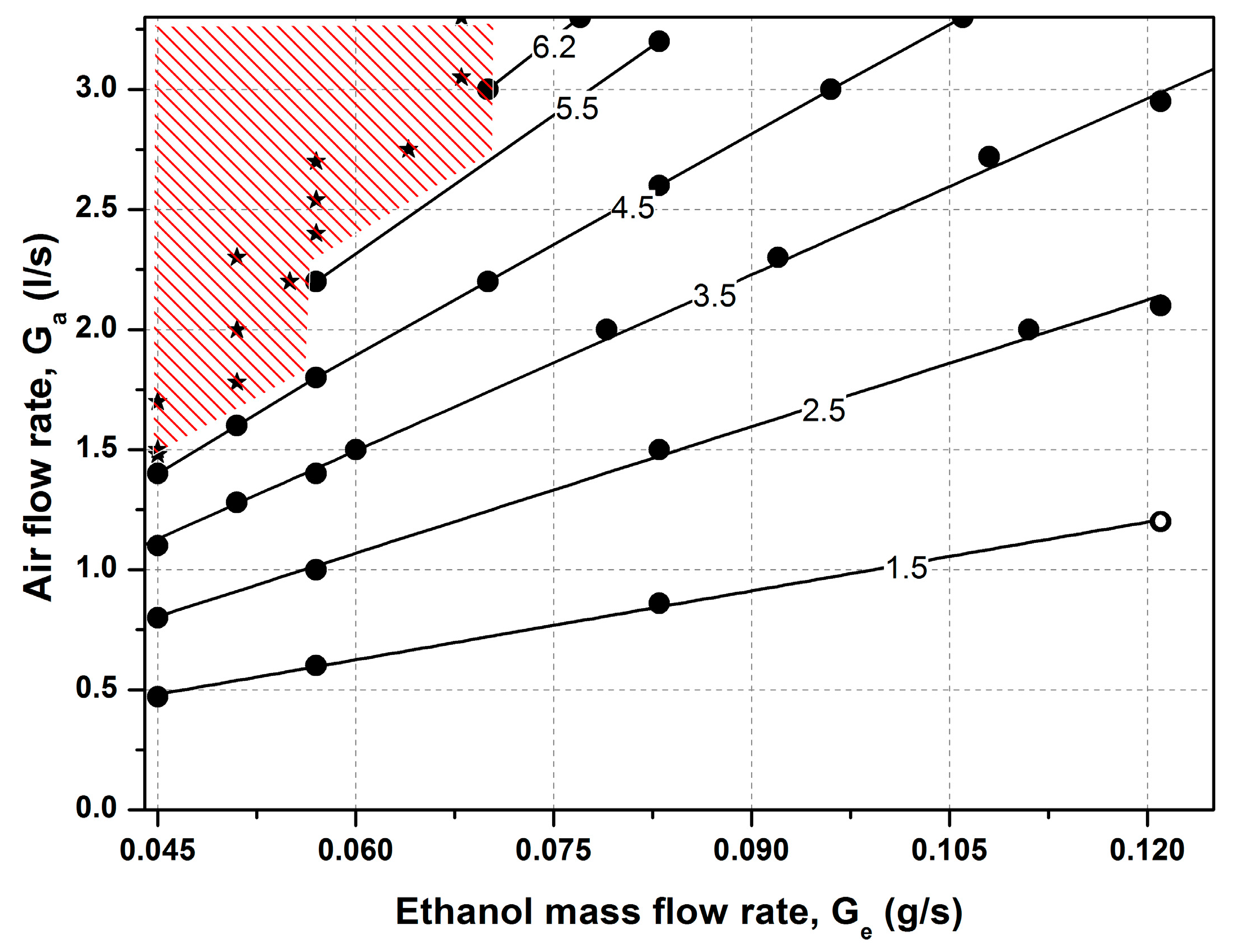
The parametric domain where experiments were performed is presented in
Figure 6 for the air flow rate—ethanol flow rate parametric plane. For leaner ethanol air mixtures and lower ethanol flow rates (shaded upper left corner of the diagram), steady established combustion was not observed. The combustion starting in the preheated reactor gradually faded. The parametric domain of the fading reaction, i.e., with lower flow rates and leaner mixtures, was apparently related to the heat loss to the environment. The parameters for the flow rates at which steady combustion regimes were established are summarized in
Table 1. The estimated Reynolds number (Re = ρuh/μ) for this air flow rate range was from 93 to 616.
Table 1 also shows the calculated values for the adiabatic combustion temperature. These values were calculated as the temperature at which the enthalpy of the reaction products equals the enthalpy of the air/96%–ethanol vapor mixture for an initial temperature equal to 78 °C (boiling point of ethanol) and an air composition of (vol.%) O
2, 20.62; N
2, 76.86; Ar, 0.92; CO
2, 0.04; and H
2O, 1.58 (air humidity of 70% at 21 °C). The enthalpies of all species, according to NIST Standard Reference Database Number 69 [
21], were used.
Because the lengths along adjacent channels are different due to the curvature of the channels, it is convenient to consider the temperature distribution within SWRs as dependent on the polar angle ϕ shown in
Figure 3. This presentation shows the adjacent points in different channels at the same angle or, in case of the passive channel, separated by 2π.
The consideration of the temperature distribution patterns within the reactor shows two distinct types of this distribution:
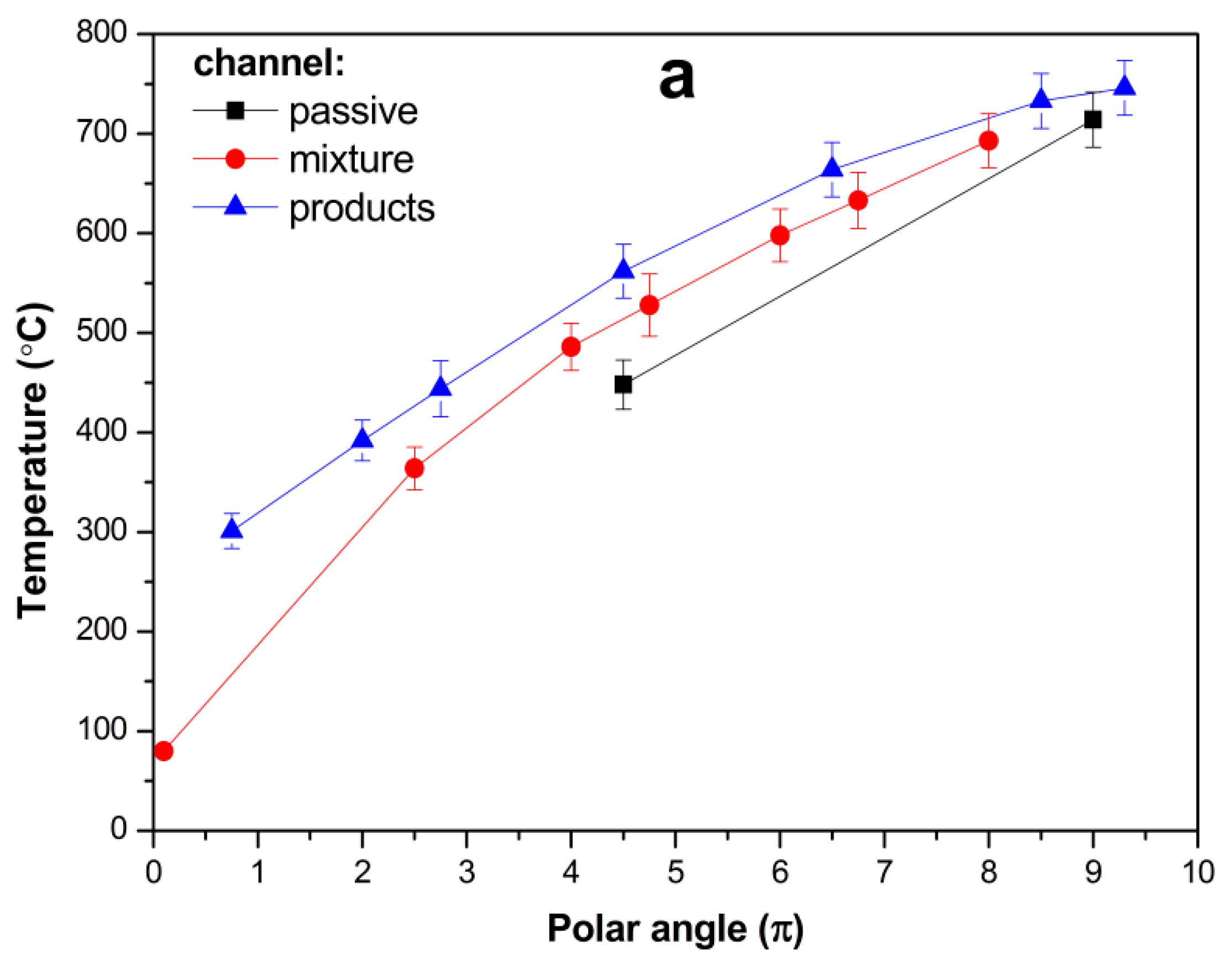
For the ethanol–air mixtures with an oxygen excess ratio α ≥ 3.5, the temperature patterns show combustion in the central part of the spiral, i.e., close to the central chamber or within it. The established temperature pattern shown in
Figure 7a (air flow rate G
a = 2.2 L/s, ethanol flow rate G
e = 0.057 g/s, α = 5.5) is typical of the experiments for α ≥ 3.5. The temperature monotonically grows along the supply channel. The maximum temperature is observed at the end of the supply channel close to the central chamber (see
Figure 3, where TC-11 indicates a high temperature in the adjacent channel), within the central chamber (TC-10), and at the entrance of the product channel (TC-9). For widely varying oxygen excess ratios and flow rates, this temperature remains at 720 ± 30 °C. The temperature in the product channel gradually decreases due to heat exchange with the supplied mixture (and to some extent we cannot quantify heat loss to the environment).
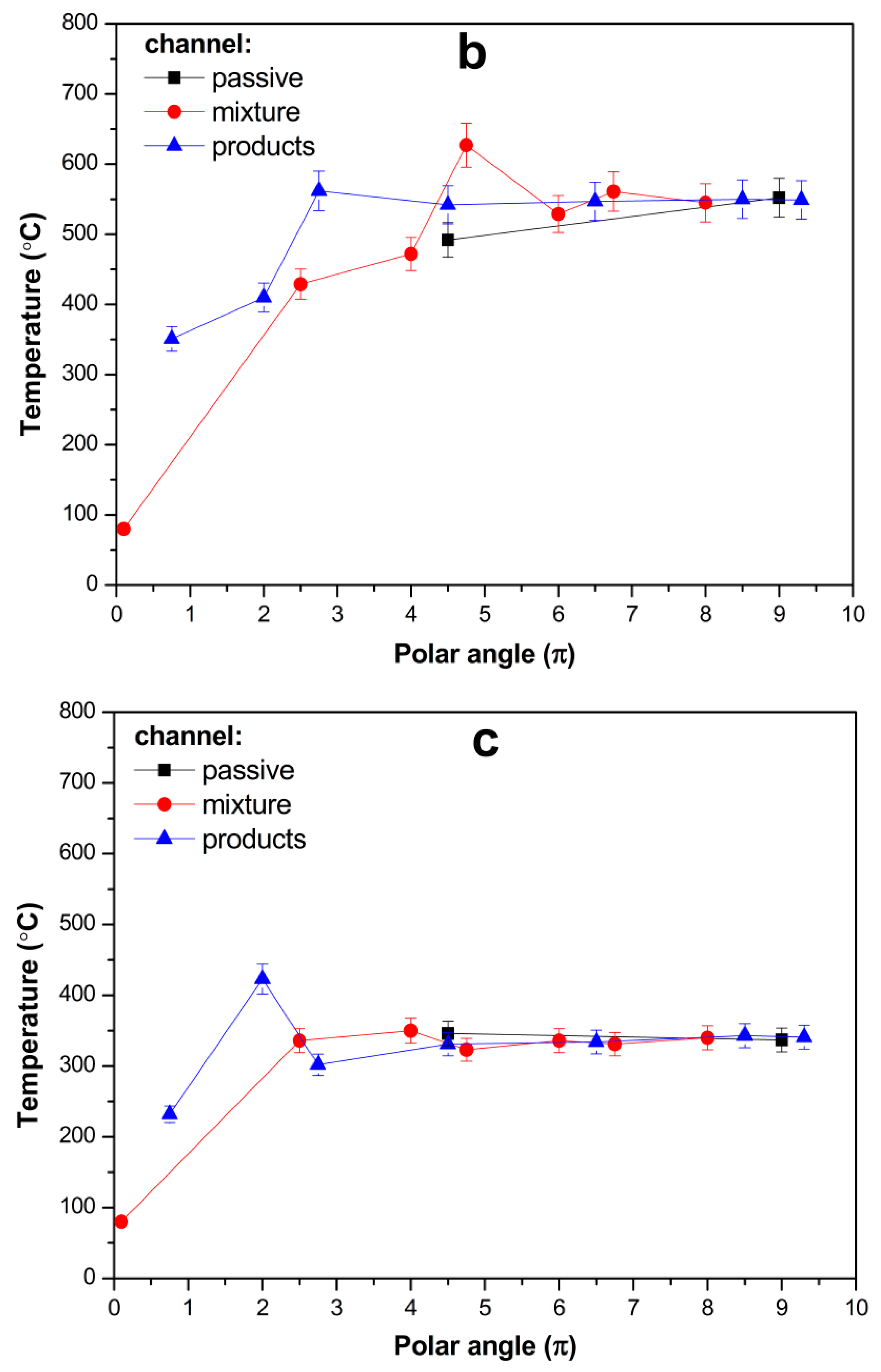
For α = 2.5 (
Figure 7b), the combustion zone obviously shifted to the supply channel. The maximum temperature was located at an intermediate position halfway along the supply channel and the interior part of the spiral. Both supply and product channels acquire virtually the same temperature, thus ceasing to be involved in the heat exchange.
For α = 1.5, at a lower flow rate, the combustion zone is apparently established close to the mixture inlet and the even temperature distribution established in the interior part of the spiral relates to the balance of the heat of combustion with the heat loss to the environment (which is obviously higher when combustion occurs in the exterior SWR winds) (
Figure 7c).
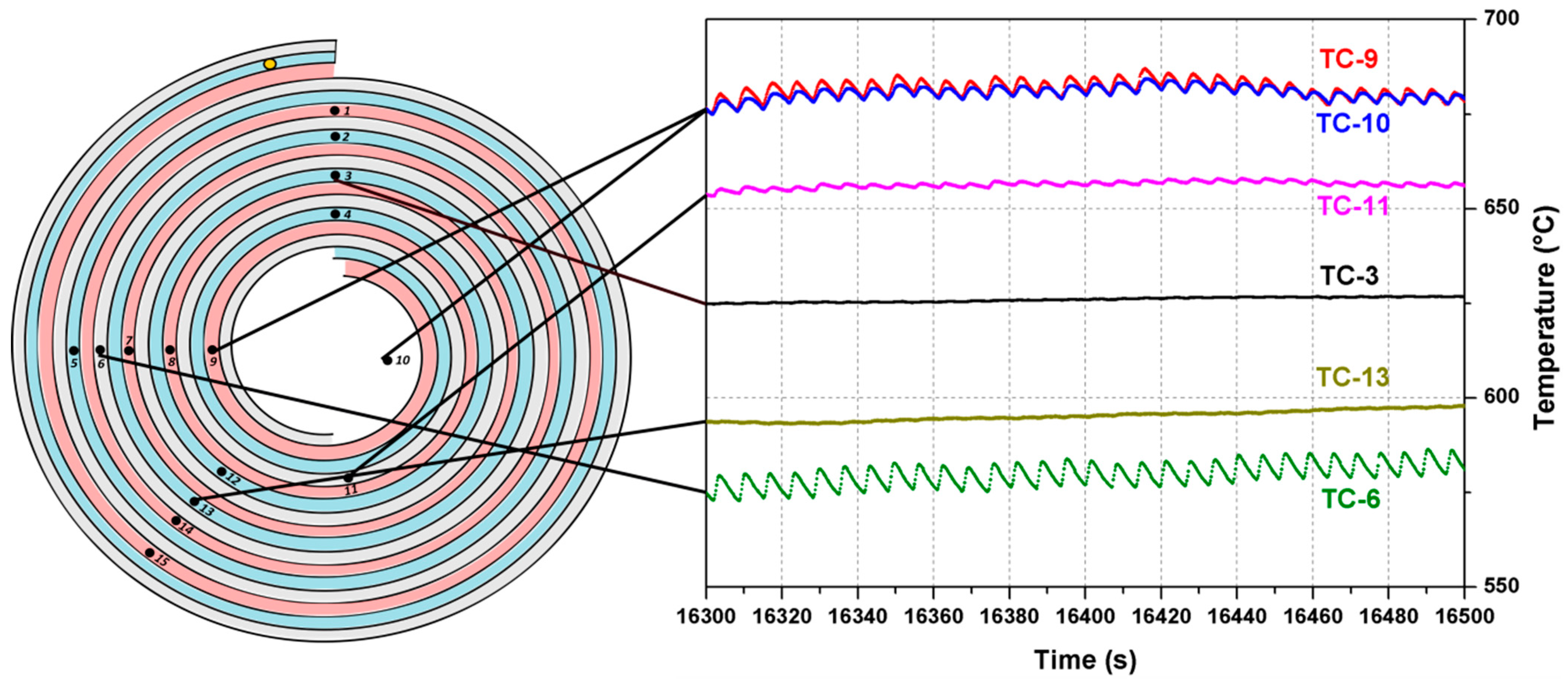
Despite the mixture with α = 1.5 can hardly be called a lean one, its behavior deserves separate attention. It was discussed before that at a lower flow rate this mixture burns within the inflow channel close to the mixture inlet. For a higher supply rate, the combustion regime for this mixture becomes oscillatory. For an air flow rate of G
a = 1.2 L/s and an ethanol flow rate of G
e = 0.121 g/s, a periodic regime was established where a depression of combustion was followed by a rapid burn. The temperature vs. time plots for several thermocouples in the established oscillatory regime are shown in
Figure 8. It should be noted that the period of oscillations (~7 s) is close to the time necessary for the mixture to fill the inflow channel.
The reactant ratios and their absolute flow rates were varied over a fairly wide range, and this had little effect on the combustion temperature. Apparently, under experimental conditions, the latter was determined by the chemical nature of the fuel and was associated with the kinetic parameters used for ethanol ignition.
The effects of the combustion zone shifting to the inflow channel and the self-adjustment of the combustion temperature, which proved to be substantially decoupled from the adiabatic combustion temperature, were previously neither observed experimentally nor predicted theoretically. The self-adjustment of the temperature pattern, i.e., the position of the combustion front closer to the mixture inlet for richer mixtures, results in a temperature increase in the outer spiral winds; this naturally brings about a higher heat loss to the environment and a decrease in the lengths of the spiral when heat recuperation occurs (x < L*, in terms of the qualitative model).


 ,
, 
