Article

Investigation of the Dynamic Characteristics of the Buffer Relief Valve of a Swing Motor Under Start–Stop Impact

1
School of Energy and Power, Lanzhou University of Technology, No. 287, Langongping Road, Lanzhou 730050, China
2
Key Laboratory of Special Pumps, Valves and Flow Control Systems, Ministry of Education, No. 287, Langongping Road, Lanzhou 730050, China
3
School of Mechanical and Automotive Engineering, Shanghai University of Engineering Science, Shanghai 201620, China
4
Qingdao LKC Hydraulic Machinery Co., Ltd., Qingdao 266000, China
*
Author to whom correspondence should be addressed.
Processes 2024, 12(12), 2689; https://doi.org/10.3390/pr12122689
Submission received: 12 November 2024 / Revised: 25 November 2024 / Accepted: 27 November 2024 / Published: 28 November 2024

Abstract

:
The swivel system of a hydraulic excavator is susceptible to pressure impact during start and stop, which significantly impacts the service life of the excavator. In this investigation into how varying speeds affect the dynamic characteristics of a swing motor’s buffer relief valve (BRV), the AMESim simulation model of the whole swing motor was established, and its validity was confirmed through experimental testing. The pressure overshoot rate and start–stop impact time of the BRV of a swing motor at 1000 rpm, 1500 rpm, and 2000 rpm, under different spring stiffnesses, were analyzed. Based on the mathematical model of the BRV, the influence of the main structural parameters of the BRV on its dynamic characteristics were analyzed using an AMESim simulation model of the whole swing motor. The results show that an increase in the rotational speed of the electric motor, while maintaining a constant spring stiffness, affects the pressure overshoot rates of both the buffer relief valve of the swing motor inlet (BRVSMI) and the buffer relief valve of the swing motor outlet (BRVSMO); specifically, when the set pressure is established at 20 MPa, the pressure overshoot rate is observed to be higher, and the start–stop impact time exceeds 25 MPa. During the start phase of the swing motor, the start impact time for the BRVSMI remains relatively constant at approximately 2.5 s, with the pressure overshoot rate stabilizing at around 0.8. Conversely, in the stop phase of swing motor, both the stop impact time and the pressure overshoot rate of the BRVSMO exhibit variability in their response to the structural parameters of the BRV. Under conditions of comparatively high pressure, it is recommended to increase the diameter of the spool damping hole, the mass of the valve core, and the viscous damping coefficient, while simultaneously reducing the guide rod diameter of the buffer plunger, as these modifications can effectively enhance the start–stop impact time and mitigate the pressure overshoot rate.

1. Introduction

A hydraulic excavator requires frequent starting and stopping of movement during its rotational operations. The substantial mass and inertia of the upper mechanism contribute to this necessity, while the vehicle’s center of gravity fluctuates in response to the bucket’s movements [1,2,3]. Although conventional construction machinery employs components such as balance valves, relief valves, and anti-reversal valves, these measures do not fully address the stability issues associated with the dynamic loading process [4,5]. Consequently, the investigation of swivel control valves for the upper mechanism is of significant importance [6,7].
For the study of the dynamic characteristics of swing motor buffer relief valves, scholars both domestically and internationally have carried out relevant research. Che, Z. et al. [8,9] analyzed a rotary buffer relief valve on the basis of a rotary drive hydraulic system and a buffer relief valve model using AMESim, through a simulation to obtain the flow and pressure of the hydraulic motor and the buffer relief valve as well as the dynamic characteristics of the swivel buffer valve. Zhao, H. [10] focused their research on a specific type of rotary drilling rig, developing a simulation model for the rotary hydraulic system associated with this equipment. Their study examined the effects of various parameters, including the spring preload of the counterbalance valve, the diameter of the conical valve, and the diameter of the damping hole, on the performance of the swing hydraulic system. Peng, L. et al. [11] suggested that during the unloading process, the initial unloading of oil results in a maximum change in momentum. Their design concept aimed to address the pressure impact generated by the electromagnetic relief valve during unloading. This was achieved by examining the relationship between the opening width of the buffer valve spool and the corresponding displacement of the spool. Si, Y. et al. [12] derived the opening curve of a buffer valve spool by examining the control of energy in the unloading valve. They subsequently validated the effectiveness of this unloading curve in mitigating pressure shocks through simulation analysis. Zhang, Y. et al. [13] conducted an investigation into the threaded cartridge cushion relief valve, specifically addressing the hydraulic shock phenomenon that arises within the motor cavity during the initiation, braking, and reversing operations of construction machinery. Their findings indicated that enhancements in cushioning performance could be achieved by reducing the diameter of the damping holes and decreasing the stiffness of the spring. Guo, Z. et al. [14] conducted an analysis of the operational characteristics of the relief valve, check valve, and anti-reversal valve within a rotary motor control valve assembly, utilizing the AMESim platform specifically for the rotary valve system of an excavator. Their study elucidated the critical parameters that influence the dynamic characteristics of a rotary mechanism. Dasgupta, K. et al. [15] employed the power bond graph methodology to model a pilot-controlled unloading valve and conducted a dynamic simulation analysis. Their findings indicated that the choice of certain critical parameters significantly influences the output transient response curve. Jin, K. et al. [16] developed a sliding mode controller utilizing the principles of sliding mode control to regulate the hydraulic excavator slewing system. This controller is capable of effectively managing the speed of the hydraulic motor, even in the presence of variations in load and the orientation of the working mechanism, thereby significantly mitigating the oscillatory behavior observed during the slewing operation. The optimization of a buffer relief valve structure uses a neural-network-based knowledge transfer method to analyze the similarities between tasks and obtain the transfer models for the information prediction of different tasks for high-quality knowledge transfer [17,18,19].
This study examines the operational principles of a swing motor and its BRV. Utilizing AMESim 2016 software, the comprehensive AMESim simulation model of a swing motor is developed. The analysis focuses on the pressure overshoot rate and the variations in the start–stop impact time of the BRV across different spring stiffness values, specifically at swing motor speeds of 1000 rpm, 1500 rpm, and 2000 rpm. Furthermore, based on the mathematical model of the BRV, this research investigates how the primary structural parameters of the BRV affect its dynamic characteristics, employing a comprehensive AMESim simulation model of the swing motor for this analysis.

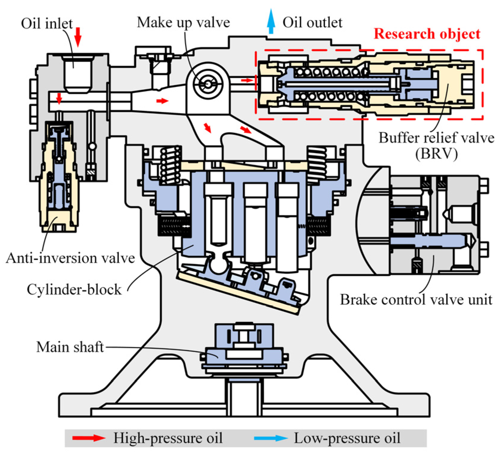
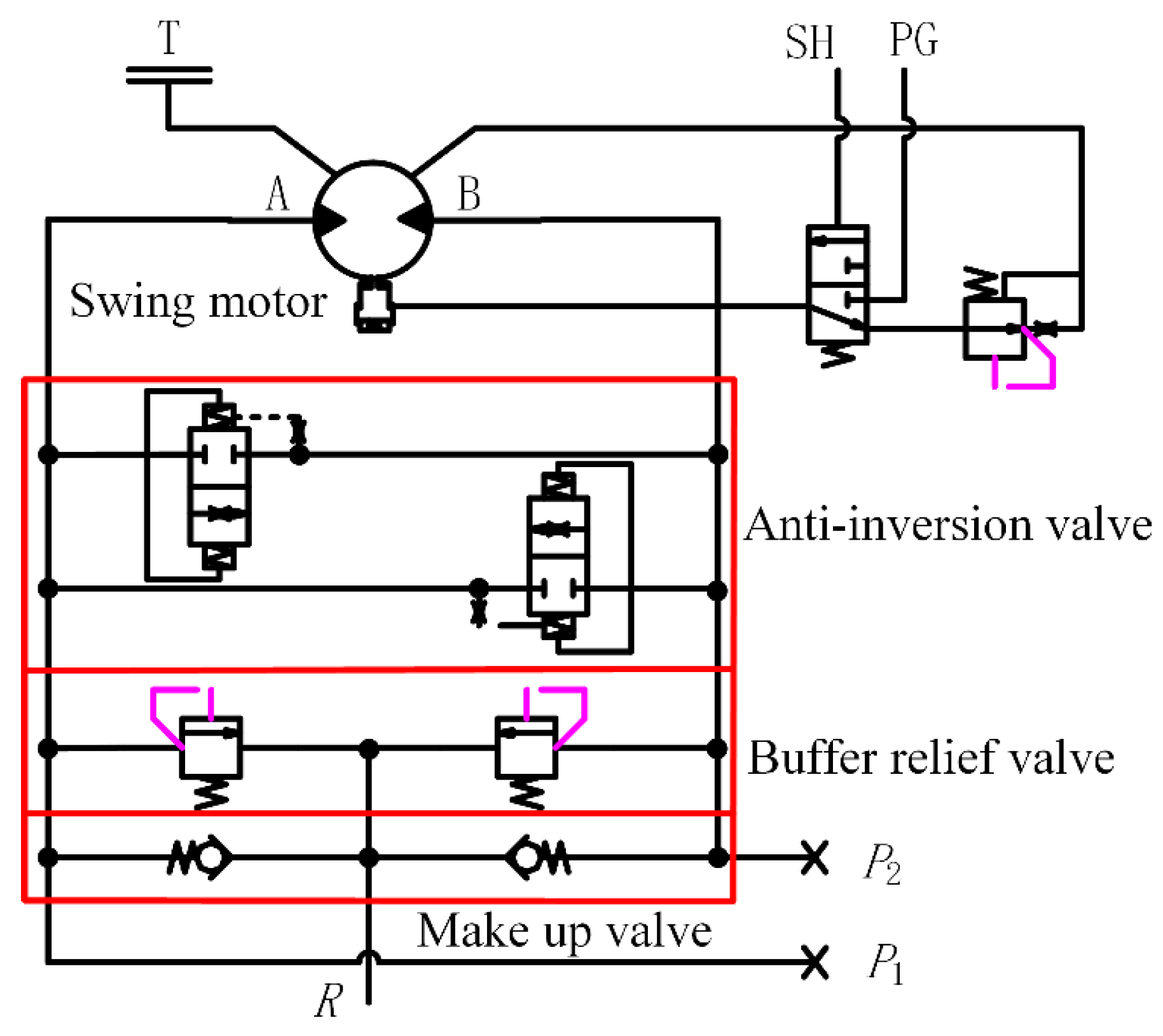
2. Working Principle of Swing Motor

The primary component of a swing motor is an axial piston motor. When high-pressure oil enters through the swing motor’s inlet, it generates axial hydraulic pressure that propels the plunger to move axially. Concurrently, the high-pressure oil exerts force on the swash plate via the slipper attached to the plunger. This interaction results in a reaction force from the swash plate, which can be decomposed into an axial force F f that balances with the hydraulic pressure on the plunger and a perpendicular force F relative to the plunger’s axial direction. The force F generates torque about the axis of the cylinder body, enabling it to rotate and overcome the load. The structural configuration of the rotary motor is illustrated in Figure 1. To enhance the stability of the swing motor during start and stop, a control valve assembly, which includes a BRV and an anti-inversion valve, is integrated into the swing motor. This assembly serves to provide buffering and prevent reverse motion. When the swing motor’s port P 1 is connected to high-pressure oil, the pressure differential between inlet A and outlet B facilitates the rotation of the swing motor. Conversely, when port P 2 is connected to high pressure oil, the operational dynamics reverse. During the stop phase of the swing motor, both ports P 1 and P 2 are simultaneously closed. Due to the inertia effect, the pressure at the original high-pressure oil port decreases while the pressure in the oil discharge chamber increases. This pressure differential causes the swing motor to oscillate in the opposite direction. The anti-inversion valve regulates this oscillation until the swing motor comes to a complete stop. The operational principles of this process are depicted in Figure 2.
Under the action of the spring preload F 0 , the spool of the BRV closes to the valve seat, thereby obstructing the pathway between the oil inlet and the oil outlet. The action area at the left end of the valve spool is denoted as A 0 , while the action area at the right end is denoted as A 1 , with the condition A 0 > A 1 . Additionally, the action area at the left end of the buffer plunger is labeled A 2 , and the action area at the right end is labeled A 3 , satisfying the inequality A 2 > A 1 + A 3 . During the braking of the rotary motor, the inlet and outlet ports are closed. Due to the inertia effect, the swing motor continues to rotate, transitioning its operational state to that of a pump, and the oil on the return oil side of swing motor is compressed, generating a high pressure that acts upon the BRV. Initially, when the pressure oil reaches the condition p s A 0 p 1 A 1 > F 0 , the valve spool initiates movement to the right, allowing oil to discharge from the oil outlet; simultaneously, oil from chamber a flows to chamber b and chamber c. When it reaches the condition p 2 A 2 p 1 A 1 p 3 A 3 > F 0 , the buffer plunger moves to the left, resulting in the compression of the main spool spring. This action leads to a continuous increase in the preload of the main spool spring, as well as a gradual rise in the oil pressure p s of the main spool. Upon the buffer plunger reaching the end of its stroke, the preload of the spring attains its maximum value. The BRV is designed to open at a lower pressure, after which the pressure incrementally increases to the predetermined set value. This mechanism serves to mitigate pressure surges during the start and stop phase of swing motor, thereby enhancing its operational performance. The structural design of the buffer overflow valve is illustrated in Figure 3.

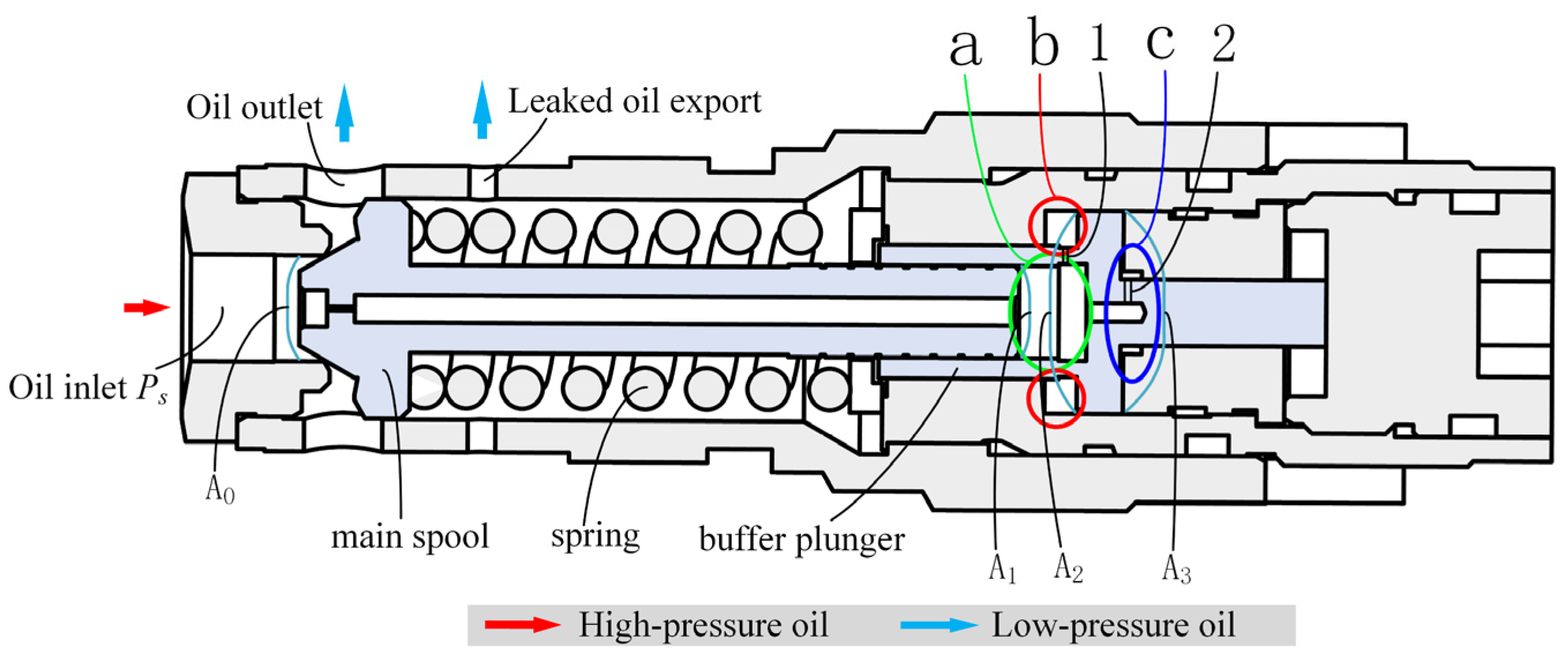
3. Establishment of Dynamic Mathematical Model of BRV

The mathematical model for the BRV is developed based on the principles of force equilibrium and flow continuity pertaining to the spool. During the mathematical modeling process, the transient hydrodynamic forces are excluded from consideration. The procedure for constructing the dynamic mathematical model is outlined as follows [20].
(1)
Force balance equation of the main spool:
p s A 0 p 1 A 1 = m 1 d x 1 2 d t 2 + k x 0 + x 1 + x 2 + B 1 d x 1 d t + k s x 1 p s
In the given formula: p s represents the oil pressure in the left chamber of the main valve spool ( Pa ); p 1 represents the oil pressure in the right cavity of the main spool ( Pa ); A 0 indicates the force area of the valve seat hole ( m 2 ); A 1 indicates the action area of the back end of the main spool ( m 2 ); m 1 signifies the mass of the main valve core ( kg ); x 0 represents the degree of spring compression (m); x 1 is the displacement of the main spool (m); x 2 is the displacement of the buffer plunger (m); k indicates the spring stiffness ( N / m ); B 1 is the kinematic viscosity damping coefficient of the spool ( N s / m ); and k s represents the hydrodynamic stiffness of the valve port, defined by the equation k s = C d 2 π d sin φ .
Valve port flow continuity equation:
q 0 = q 1 + q x + V 0 E d p s d t
q 1 = G R 01 p s p 1
q x = C d 1 π d 0 x 1 sin φ 2 p s ρ K q x x 1 + K c x p s
In this equation: q 0 represents the inflow into the BRV ( m 3 / s ); q 1 represents the flow rate passing the throttle orifice and the damping hole ( m 3 / s ); q x represents the flow through the valve port ( m 3 / s ); V 0 refers to the volume of the valve port’s front chamber ( m 3 ); E represents the bulk-modulus of the oil ( Pa ); C d 1 is the flow coefficient of the valve port; φ represents the taper angle of the valve core (°); and G R 01 corresponds to the series liquid group associated with the throttle orifice and the damping hole, defined by the following equation:
G R 01 = G R 0 G R 1 G R 0 + G R 1
(2)
Buffer plunger force balance equation:
p 2 A 2 p 3 A 3 p 1 A 1 = m 2 d x 2 2 d t 2 + k x 0 + x 1 + x 2 + B 2 d x 2 d t
In this equation: p 2 represents the pressure in the right cavity of the buffer plunger ( Pa ); p 3 represents the pressure in the left chamber of the buffer plunger ( Pa ); A 2 refers to the effective area of the right cavity of the buffer plunger ( m 2 ); A 3 refers to the effective area of the left cavity of the buffer plunger ( m 2 ); B 2 is defined as the damping coefficient related to the kinematic viscosity of the buffer plunger( N s / m ); and m 2 represents the mass of the buffer plunger ( kg ).
Buffer plunger flow continuity equation:
q 1 = q 2 q 3 + V 1 E d p 1 d t A 1 d x 1 d t A 1 d x 2 d t
q 2 = C d 2 A d 2 2 p 1 p 2 ρ = A 2 d x 2 d t + V 2 E d p 2 d t
q 3 = C d 3 A d 3 2 p 3 p 1 ρ = A 3 d x 2 d t + V 3 E d p 3 d t
In this equation: q 2 represents the flow rate through orifice 2 ( m 3 / s ); C d 2 represents the flow coefficient associated with orifice 2; q 3 represents the flow rate through orifice 1 ( m 3 / s ); C d 3 refers to the corresponding flow coefficient for orifice 1; A d 2 is the boundary area of orifice 2 ( m 2 ); A d 3 is the boundary area of orifice 1 ( m 2 ); V 1 represents the volume of the back cavity of the spool ( m 3 ); V 2 represents the volume at the right end of the buffer plunger ( m 2 ); and V 3 represents the volume at the left end of the buffer plunger ( m 3 ).
Equation (1) is employed to address the differential equation of a linear system utilizing the Laplace transform. This approach facilitates the derivation of the relationship between the main spool displacement, denoted as x 1 s , and the valve inlet pressure, represented as p s s , of the BRV. Additionally, it establishes the correlation between the pressure at the right end, p 1 s , of the main spool, and the displacement of the buffer plunger, x 2 s .
x 1 s = A 0 k s x 1 s p s s p 1 s A 1 k x 2 s m 1 s 2 + k + B 1 s + k s p s s
From Equations (2) and (3), one can derive the relationship between the inlet pressure p s s and flow q 0 s of the BRV, as well as the pressure p 1 s at the right end of the main spool and the displacement x 1 s of the main spool. Additionally, Equation (4) provides the relationship between the flow rate q 1 s and the inlet pressure p s s , and p 1 s is associated with the main spool combination orifice.
p s s = q 0 s + G R 01 p 1 s k q x x 1 s G R 01 + k c x + V 0 E s
q 1 s = G R 01 p s s p 1 s
From Equation (5), one can derive the relationship between the pressure p 2 s and the displacement x 2 s at the right end of the buffer plunger, as well as the pressure p 3 s , x 1 s , and p 1 s at the left end of the buffer plunger.
x 2 s = p 2 s A 2 p 3 s A 3 p 1 s A 1 k x 1 s m 2 s 2 + B 1 s + k
The correlation between the flow rate q 2 s and p 1 s of orifice 2, as well as the flow rate q 3 s , q 1 s , and the x 1 s , x 2 s associated with orifice 1, can be obtained from Equation (6).
p 1 s = q 1 s q 2 s + q 3 s + A 1 s x 1 s + A 2 s x 2 s V 1 E s
The relationships among p 2 s and p 1 s , x 2 s , and q 2 s , as well as p 1 s and p 2 s , can be derived from Equation (7).
p 2 s = k q 2 p 1 s A 2 s x 2 s V 2 E s + k q 2
q 2 s = k q 2 p 1 s p 2 s
In this equation, k q 2 = C d 2 A d 2 2 2 ρ p 10 p 20 .
The relationships among p 3 s and p 1 s and x 2 s , as well as q 3 s and p 1 s and p 3 s , can be derived from Equation (8).
p 3 s = k q 3 p 1 s + A 3 s x 2 s V 2 E s + k q 3
q 3 s = k q 3 p 3 s p 1 s
In this equation, k q 3 = C d 3 A d 3 2 2 ρ p 30 p 10 .
The transfer function of the buffer relief valve is a complex system involving multiple loops and cross-feedback, making it challenging to determine the overall transfer function. This function can be broken down into the main valve component and the buffer plunger component, with a qualitative analysis conducted using the main valve as an example. The transfer function for the main valve section is defined by Equations (9) and (10). These equations linearize the dynamic behavior of the spool around the rated operating point, where q 0 s serves as the input and x 1 s as the output. The control loop includes a first-order inertial link, a second-order oscillatory link, and a first-order differential link.
Total open-loop gain of the loop:
K 1 = K q x K c x 1 k + K s x ; in this equation, K q x = q x x 1 (Main valve orifice flow gain), K q x = q x x 1 (Main valve orifice flow pressure coefficient), and K s x = k s p s .
Frequency of the first-order inertial link: ω v = E K c x V 0 .
Frequency of the second-order oscillatory link: ω x = k + K s x m 1 .
Frequency of the first-order differential link: ω a = K q x A 0 .
(1)
Because of the significant flow gain of the main valve (with a motor displacement of 63 mL/r), the frequency ω a for the first-order differentiation step is relatively high.
(2)
The volume of the cavity situated in front of the main valve is substantial, resulting in a relatively low frequency for the first-order inertia link, which consequently exerts a predominant influence. In the design of the buffer relief valve, the choice of the main valve orifice diameter, as indirectly indicated by parameter A 0 , significantly impacts the analysis of the dynamic characteristics of the buffer relief valve.
(3)
The mass of the primary spool, the stiffness of the reset spring, and the hydraulic stiffness will have an impact on the second-order oscillation link of the intrinsic frequency. The effects of the second-order oscillation should not be overlooked. Additionally, the use of the main spool machining damping holes (reasonable damping hole diameter and length) as the dynamic pressure feedback can be effective in suppressing the oscillation of the second-order link of the oscillating effect.

4. Verification of the Rationality of AMESim Simulation Model

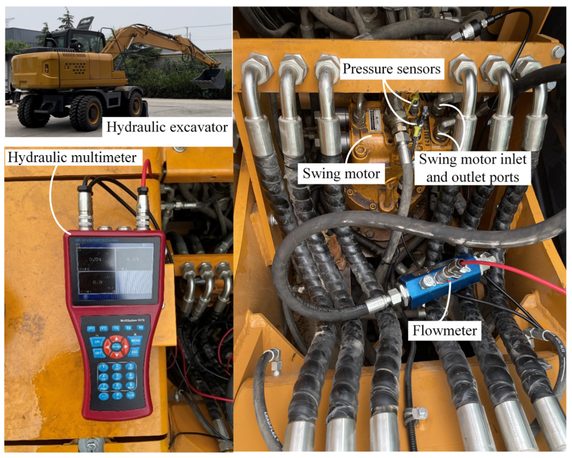
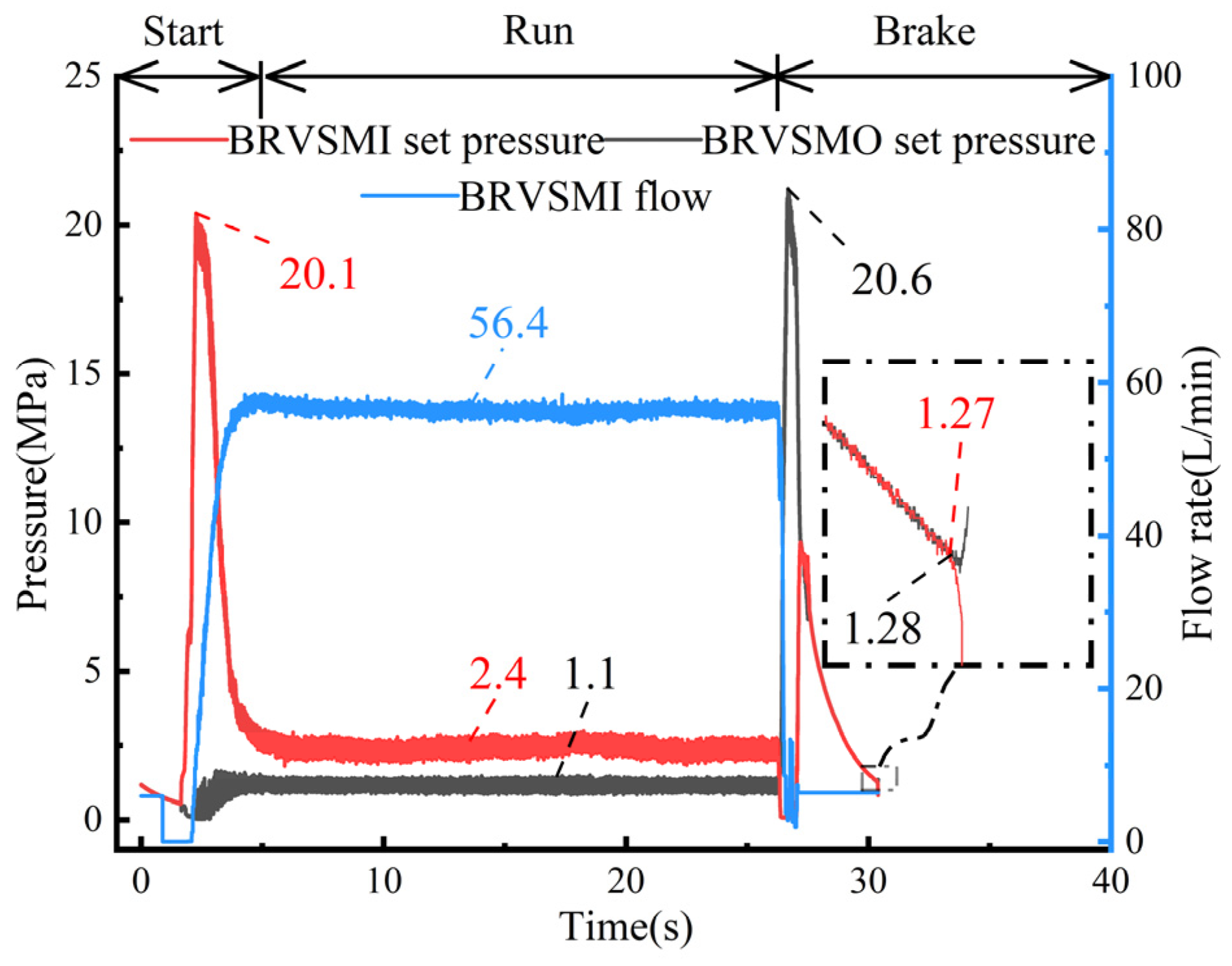
4.1. Swing Motor Complete Machine Test

As illustrated in Figure 4, the swing motor test involved the establishment of a pressure interface at both the inlet and the outlet of the swing motor for the purpose of conducting pressure assessments. Concurrently, a flow meter was installed in the oil inlet pipe to measure the volumetric flow rate entering the rotary motor. Additionally, a hydraulic multimeter was employed to gather and analyze the pressure and flow data associated with the rotary motor. To facilitate a quantitative assessment of the start and stop impact time, the start impact time is defined as the duration required to reach 10% of the maximum opening pressure, while the stop impact time is characterized as the moment when the pressure stabilizes within ±10% of the final constant pressure.
During the swing motor test, the set pressure of the BRV was established at 20 MPa. The corresponding measured curve at a motor speed of 1000 r/min is illustrated in Figure 5. Analysis of the test curve indicates that the opening pressure of the buffer relief valve of the swing motor inlet (BRVSMI) was 20.1 MPa. The duration of the start impact, which is the time interval from the opening to the closing of the BRV, was recorded as 2.60 s. Following this period, the rotary motor transitioned into a phase of stable operation, during which the inlet pressure was measured at 2.4 MPa, the pressure at the motor’s return port was 1.1 MPa, and the flow rate at the motor’s inlet port was 56.4 L/min. After 26.33 s, the oil supply to both the inlet and outlet of the motor ceased simultaneously. At this point, the pressure of buffer relief valve of the swing motor outlet (BRVSMO) increased to 20.6 MPa. Subsequently, the pressure gradually decreased, reaching an inlet pressure of 1.27 MPa and an outlet pressure of 1.28 MPa after 30.36 s. The pressures at the inlet and outlet of the rotary motor equalized, resulting in the cessation of the motor’s oscillation, with the stop impact time recorded at approximately 4.03 s.

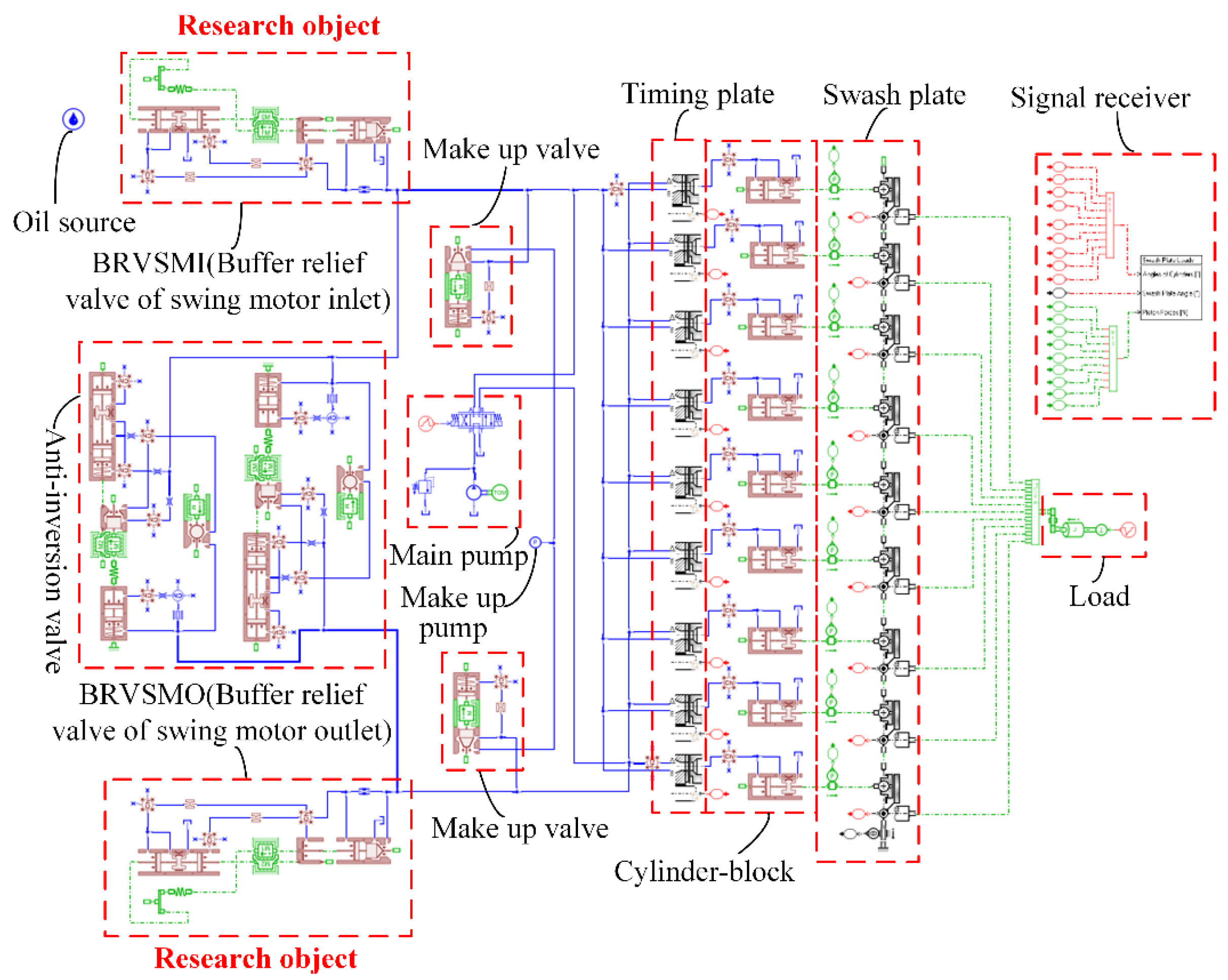
4.2. Overall AMEim Modeling of Rotary Motor

As illustrated in Figure 6, the overall simulation model of the swing motor (swash plate axial piston type) in AMESim comprises several components. These include a hydraulic oil source, which allows for the configuration of various hydraulic oil parameters such as density, bulk modulus, and dynamic viscosity. The model also features a cylinder plunger section, where the magnitude of the plunger force is monitored via a green sensor, while the plunger angle is detected through a red sensor. Additionally, the inclination of the motor’s swash plate is measured by a black signal sensor. Furthermore, the model incorporates a BRV, an anti-reversal valve, and a make-up valve, which are installed at the inlet and outlet of the swing motor, along with the main pump and load [21].
In the context of hydraulic component simulation, both the comprehensive modeling and the parameter configurations of the critical components within the hydraulic system model significantly influence the simulation outcomes. The essential structural parameters utilized in the simulation model are derived from empirical measurements, with the structural parameters pertaining to the entire swing motor presented in Table 1.
The motor is set to a speed of 1000 revolutions per minute (r/min) and a pump displacement of 140 cubic centimeters per revolution (cc/r). The three-position, four-way solenoid reversing valve is positioned to the right from 0 to 20 s, transitioning to a neutral state from 20 to 40 s. The simulation utilizes a time step of 0.001 s, culminating in a total simulation duration of 40 s. The input signal for the directional valve is illustrated in Figure 7, and the resulting simulation data for the inlet and outlet pressures, as well as the flow curves of the swing motor, are presented in Figure 8.
As illustrated in Figure 8, during the initial start phase of swing motor, the opening pressure of the BRVSMI is recorded at 20.8 MPa. The duration of the start impact, from the BRV’s opening to its closure, is measured at 2.94 s. Following this interval, the swing motor successfully transitions the rotary device into a phase of smooth operation, characterized by an inlet pressure of 1.7 MPa and a return pressure of 0.2 MPa, with an operational flow rate of 56.6 L/min. After 20 s, the three-position, four-way electromagnetic directional valve is shifted to the neutral position, simultaneously closing the inlet and outlet of the swing motor. Despite this closure, the swing motor continues to rotate due to inertia. At this juncture, the pressure at the BRVSMO increases to 19.2 MPa, subsequently declining over time. At 23.61 s, the inlet pressure of the swing motor is recorded at 0.19 MPa, while the return port pressure is slightly lower at 0.17 MPa. The pressures at the inlet and outlet ports of the swing motor approach equilibrium, and the simulation curve closely aligns with the experimental curve in numerical terms. The discrepancy in the start impact time of the BRV, as derived from both the simulation and experimental data, falls within acceptable limits, as detailed in Table 2. This finding suggests that the AMESim model of the swing motor is capable of accurately calculating the dynamic characteristics of the BRV. As shown in Figure 8, points A and B are the start impact time and points C and D are the stop impact time [22].

5. Results and Discussion

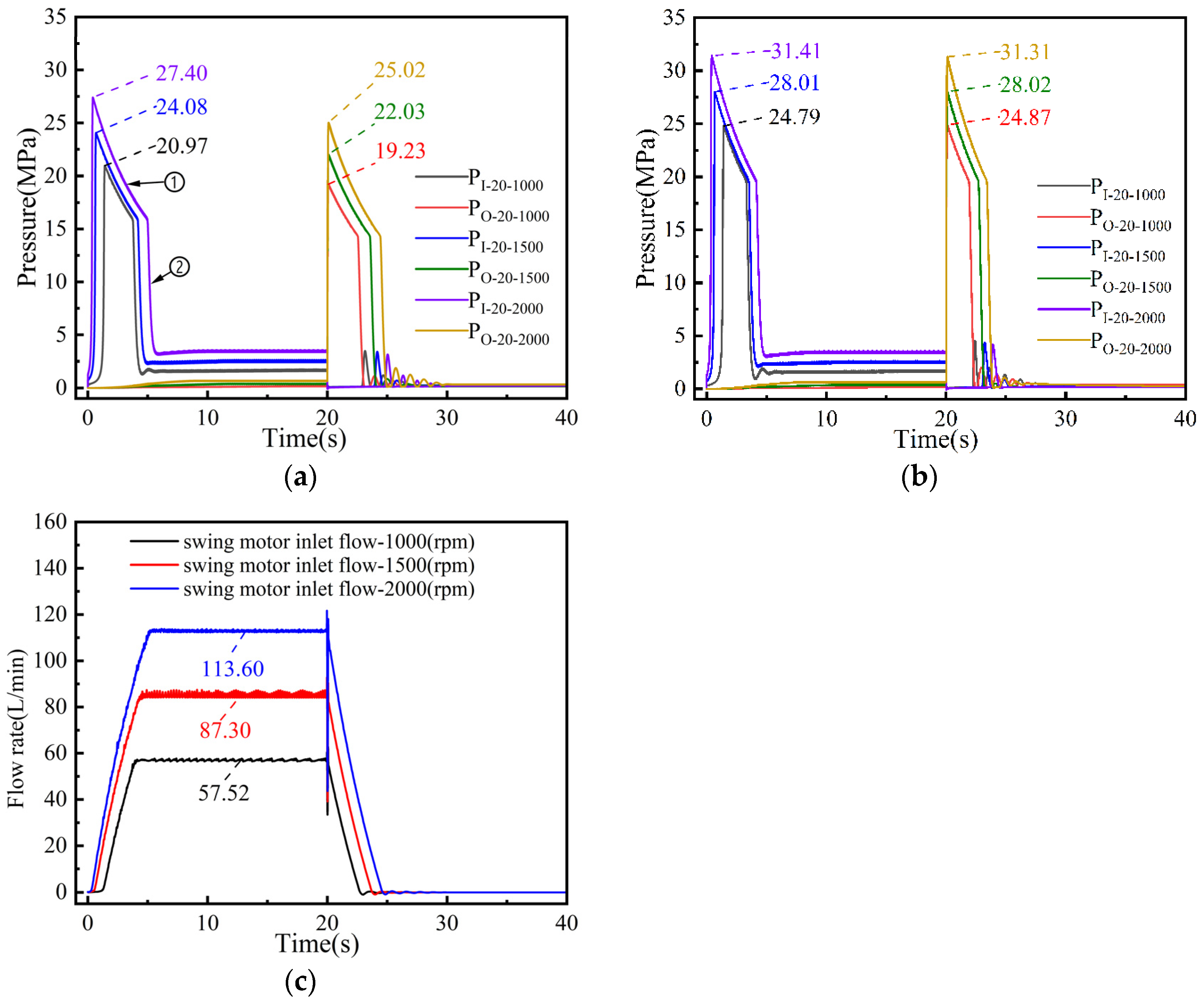
5.1. Simulated Pressure Curves of the Inlet and Outlet of the Swing Motor at 1000, 1500, and 2000 rpm

5.1.1. Dynamic Characterization of BRV Under Different Swing Motor Speeds with Spring Stiffness k = 136 N/mm and Setting Pressure at 20 MPa and 25 MPa, Respectively

P I 20 1000 and P O 20 1000 in Figure 9 represent the start–stop impact pressure magnitude, where I represents the buffer relief valve of swing motor inlet, O represents the buffer relief valve of the swing motor outlet, 20 represents the BRV setting pressure, and 1000 represents swing motor speed; the symbols have the same meaning in Figure 10.
As illustrated in Figure 9a, when the BRV is set to a pressure of 20 MPa, the impact pressure at the BRVSMI during the initial phase of motor operation reaches values of 20.97 MPa, 24.08 MPa, and 27.40 MPa at rotational speeds of 1000 rpm, 1500 rpm, and 2000 rpm, respectively. Following a duration of 20 s, as the swing motor transitions into the braking phase, the impact pressure at the BRVSMO is recorded at 19.23 MPa, 22.03 MPa, and 25.02 MPa for the same respective speeds of 1000 rpm, 1500 rpm, and 2000 rpm. In Figure 9b, it is observed that at a BRV setting pressure of 25 MPa, the impact pressure at the BRVSMI attains values of 24.79 MPa, 28.01 MPa, and 31.41 MPa for swing motor speeds of 1000 rpm, 1500 rpm, and 2000 rpm, respectively. Furthermore, during the braking phase of the swing motor, after a duration of 20 s, the impact pressure at the BRVSMO reaches 24.87 MPa, 28.03 MPa, and 31.31 MPa at the same swing motor speeds of 1000 rpm, 1500 rpm, and 2000 rpm, respectively. Under the same spring stiffness, the BRV impact pressure becomes larger with an increase in rotational speed, the BRV start–stop impact time increases with an increase in rotational speed, the start–stop impact time is shortened, and the response speed becomes faster when the BRV set pressure changes from 20 MPa to 25 MPa. The theoretical displacement of the swing motor is 63 mL/r, and the flow rate at 1000 rpm, 1500 rpm, and 2000 rpm is 63 L/min, 94.5 L/min, and 126 L/min, respectively, according to the flow rate formula q = v n . The inlet flow curve of swing motor obtained by simulation is shown in Figure 9c; the maximal error between the theoretical flow rate and simulated flow rate is 9.8%.

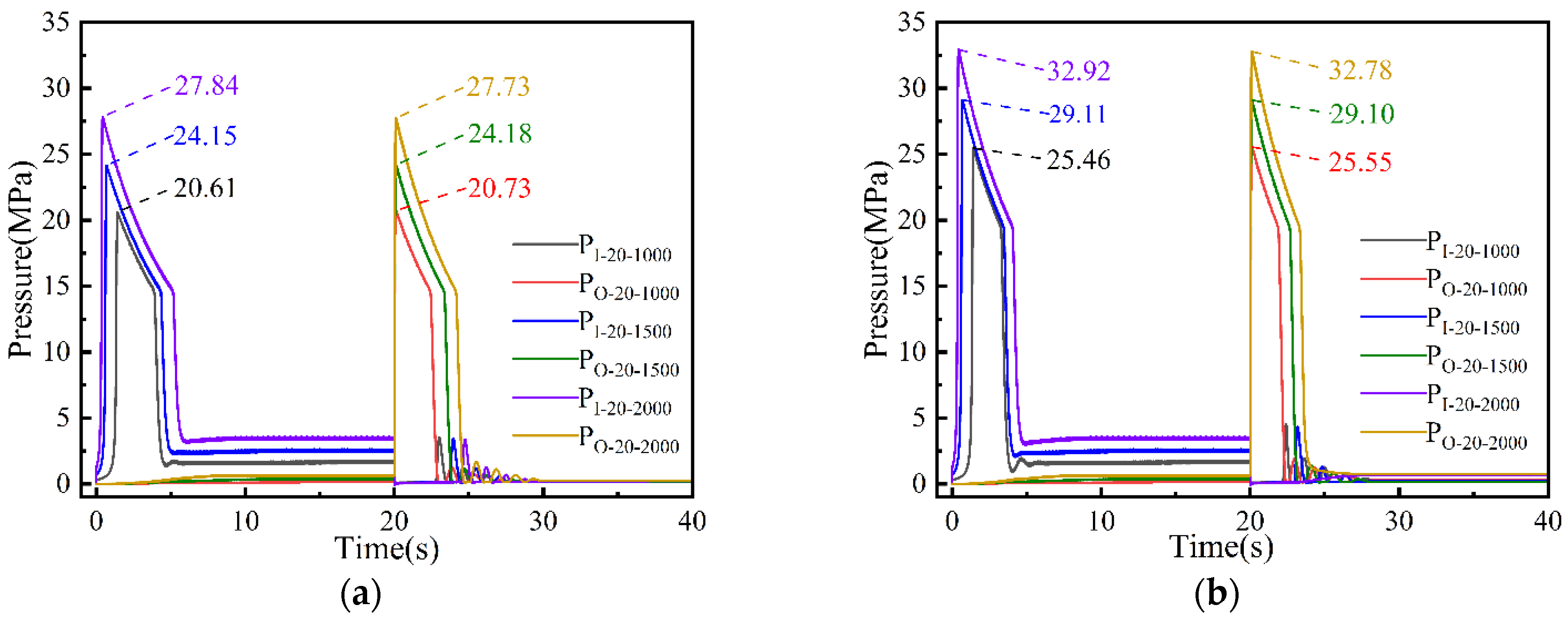
5.1.2. Dynamic Characterization of BRV Under Different Swing Motor Speeds with Spring Stiffness k = 220 N/mm and Setting Pressure at 20 MPa and 25 MPa, Respectively

The spring stiffness of the primary spool in the BRV was calibrated to 220 N/mm, with the set pressures of the valve established at 20 MPa and 25 MPa. As illustrated in Figure 10, the trend in pressure variation corresponds with that observed when the spring stiffness was set to 136 N/mm. Specifically, Figure 10a indicates that during the starting phase of the swing motor, the BRVSMI experiences an initial increase in shock pressure. The peak pressures recorded at swing motor speeds of 1000 rpm, 1500 rpm, and 2000 rpm are 20.61 MPa, 24.15 MPa, and 27.84 MPa, respectively. Furthermore, during the braking phase of the swing motor, which occurs after 20 s, the shock pressure of the BRVSMO also exhibits an initial increase. The peak pressures observed at the same swing motor speeds of 1000 rpm, 1500 rpm, and 2000 rpm are 20.73 MPa, 24.18 MPa, and 27.73 MPa, respectively. As illustrated in Figure 10b, when the BRV is set to a pressure of 25 MPa, the peak impact pressures of the BRVSMI at motor speeds of 1000 rpm, 1500 rpm, and 2000 rpm are recorded at 25.46 MPa, 29.11 MPa, and 32.92 MPa, respectively. Furthermore, during the braking phase of swing motor after 20 s, the impact pressures of the BRVSMO are measured at 25.55 MPa, 29.10 MPa, and 32.78 MPa for motor speeds of 1000 rpm, 1500 rpm, and 2000 rpm, respectively. Subsequently, these impact pressures gradually decline until the pressures at the inlet and outlet of the rotary motor approach equilibrium, resulting in the cessation of swing motor oscillation. In Figure 9a, it is evident that once the opening buffer pressure reaches its maximum value, a decrease in pressure ensues, characterized by two distinct curves with varying slopes, denoted as ① and ② in the pressure decline trend. The behavior observed in curve ① can be attributed to the combined effects of the throttling action of damping orifice 2 and the spring mechanism during the reset of the buffer plunger to its original position. In contrast, curve ② reflects a scenario where only the spring is responsible for resetting the spool. This suggests that enhancing the response time could be achieved by modifying the action area of the buffer plunger, a phenomenon that is also evident in Figure 9b and Figure 10a,b.

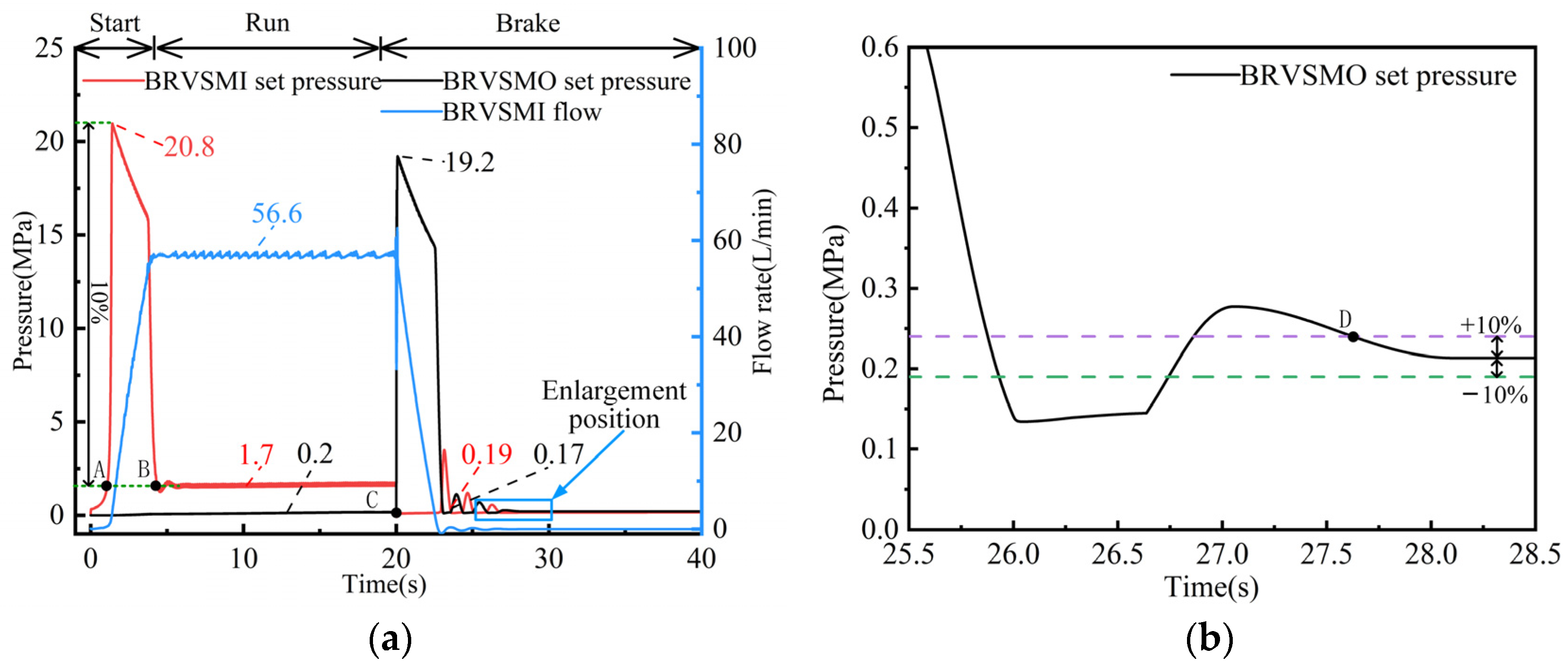
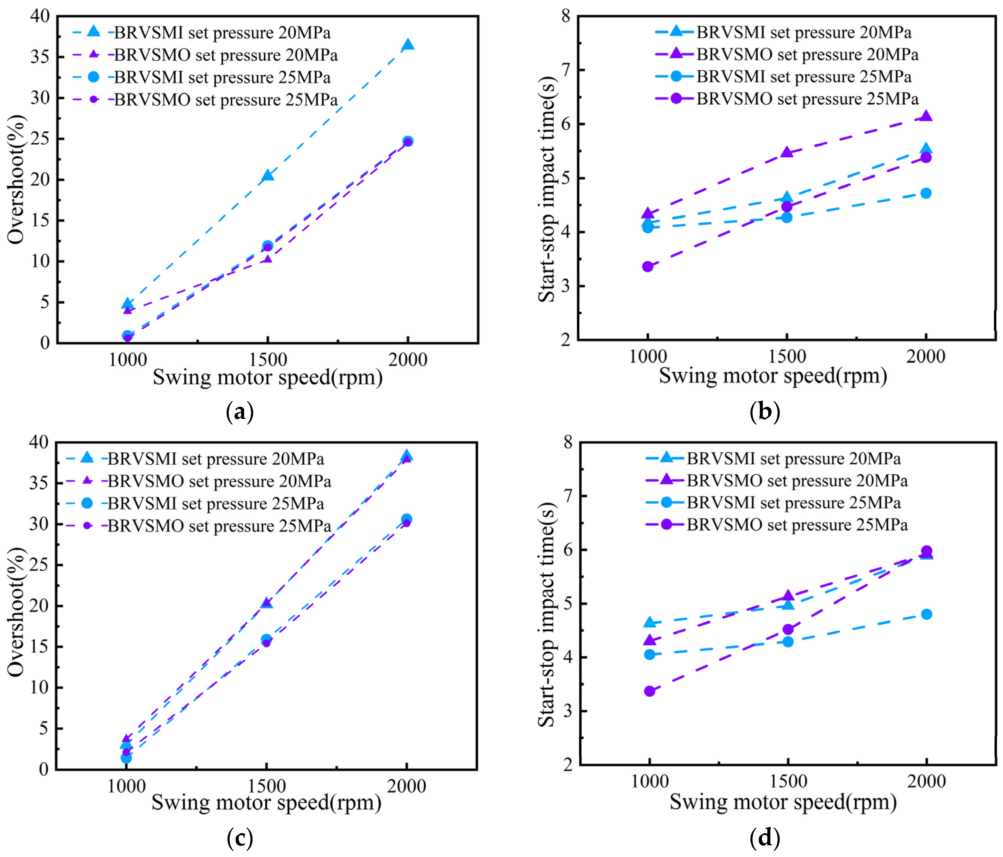
5.2. Analysis of BRV Pressure Overshoot Rate and Impact Time Under Start–Stop Impact

Analysis of Figure 11a,c reveals that, under varying spring stiffness values (k = 136, 220 N/mm), the pressure overshoot rate of the BRVSMI and BRVSMO at set pressures of 20 MPa and 25 MPa, and the pressure overshoot rate at a 20 MPa set pressure of the BRVSMI, are greater than the pressure overshoot rate at 25 MPa. This phenomenon can be attributed to the fact that when the impact pressure increases, the buffer plunger exerts greater compression on the spring, thereby enhancing the buffering effect against the impact pressure. Notably, the BRV associated with swing motor return port demonstrates superior buffering capabilities. The correlation between increased impact pressure and enhanced compression of the buffer plunger on the spring further substantiates this observation. The pressure overshoot rate of the BRVSMO at set pressures of 20 MPa and 25 MPa exhibits a similar trend, indicating a positive correlation with an increase in swing motor speed. Furthermore, as illustrated in Figure 11b,d, the duration of start–stop impact time increases approximately linearly with swing motor’s rotational speed. Specifically, the start–stop impact time for BRVSMI at a set pressure of 20 MPa exceeds that of the BRVSMI at a set pressure of 25 MPa. The BRVSMO follows a similar trend, suggesting that elevated pressure levels influence the operational dynamics of the BRV in relation to the buffer plunger. This indicates that an increase in pressure prompts the BRV to adjust the spring preload dynamically in response to the impact pressure, thereby reducing the start–stop impact duration and mitigating the pressure impact during start–stop operations [23].

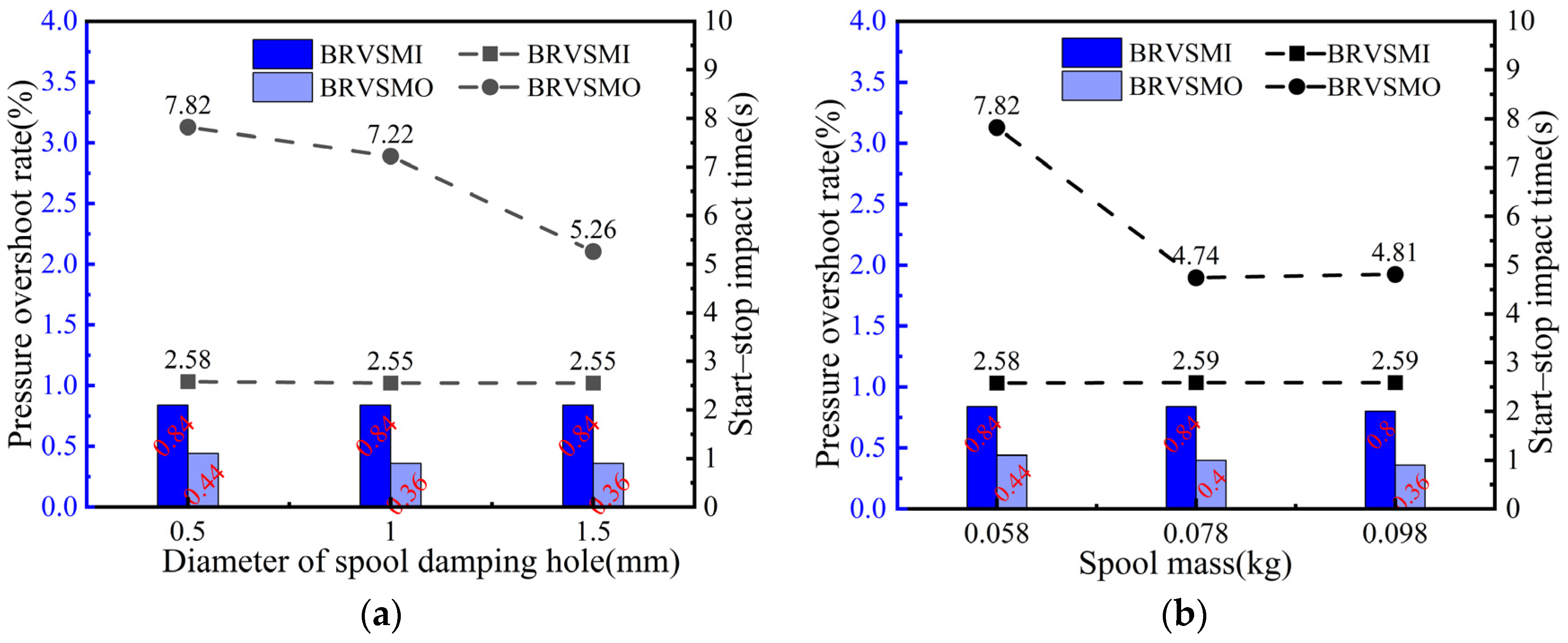
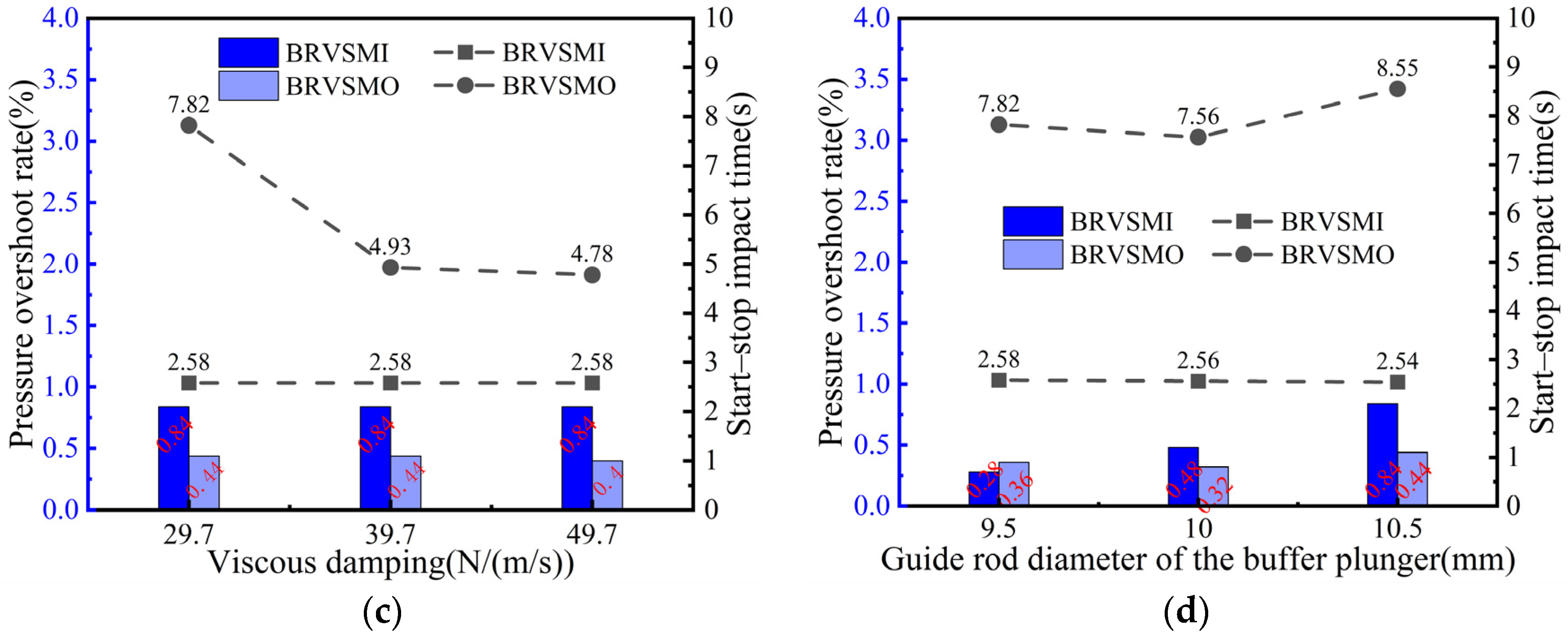
5.3. Influence of Major Structural Parameters of BRV on Dynamic Characteristics

The dynamic mathematical model of the BRV presented in Section 2 demonstrates that various structural parameters, including spring stiffness, spool mass, and damping holes, significantly impact the response time of the BRV. A simulation and analysis of the effects of the primary structural parameters on the dynamic characteristics of the BRV were conducted under specific conditions: a swing motor rotational speed of 1000 rpm, a set pressure of 25 MPa, and a spring stiffness of k = 136 N/mm.
As illustrated in Figure 12a, during the starting phase, the swing motor operates in motor mode. It can be observed that as the diameter of the damping hole in the BRV spool increases, the starting impact duration of the BRVSMI remains approximately constant at 2.55 s. Conversely, during the braking phase, the swing motor transitions from motor mode to pump mode, resulting in a reduction in the brake impact duration for the BRVSMO, from 7.82 s at a damping hole diameter of 0.5 mm, to 5.26 s at a diameter of 1.5 mm, indicating that an increase in the damping hole diameter leads to a reduction in the time required for pressure fluctuation attenuation and stabilization. The pressure overshoot rate for the BRVSMI is maintained at 0.84, while the pressure overshoot rate for the BRVSMO remains relatively stable at 0.36. For hydraulic excavators, it is recommended that the BRVSMO pressure overshoot rate be maintained at 0.36. Therefore, for high-pressure hydraulic systems in hydraulic excavators, a damping orifice diameter of 1.5 mm should be selected [7,14]. As illustrated in Figure 12b, the starting impact duration of the BRVSMI is consistently recorded at approximately 2.59 s. In contrast, the braking impact duration of the BRVSMO attains a minimum value of 4.74 s when the spool mass is set at 0.078 kg. Furthermore, the pressure overshoot rate for the BRVSMI remains relatively stable at 0.84, while the pressure overshoot rate for the BRVSMO exhibits a gradual decline. As illustrated in Figure 12c, the starting impact duration for the BRVSMI is consistently recorded at 2.58 s. Furthermore, it is observed that the braking shock duration for the BRVSMO diminishes as the viscous damping coefficient increases. The pressure overshoot rate for the BRVSMI remains relatively stable at approximately 0.8, while the pressure overshoot rate for the BRVSMO is consistently maintained at around 0.4. From Figure 12d, it can be seen that reducing the diameter of the buffer plunger guide bar is equivalent to increasing the effective action area of the buffer plunger A 3 , the starting impact time of the BRVSMI decreases with an increase in the guide rod diameter of the buffer plunger, and the braking impact time of the BRVSMO reaches a minimum of 7.56 s when the guide rod diameter of the buffer plunger reaches 10 mm. The pressure overshoot rate of the BRVSMI gradually increases with an increase in the diameter of the buffer plunger guide rod, and the pressure overshoot rate of the BRVSMO reaches a minimum of 0.32 when the guide rod diameter of the buffer plunger reaches 10 mm. In summary, under larger pressure conditions, appropriately increasing the diameter of the spool damping hole, spool mass, and viscous damping coefficient to improve the start–stop impact time, and reducing the guide rod diameter of the buffer plunger, can effectively reduce the pressure overshoot rate.

6. Conclusions and Future Work

The overall AMESim simulation model of the swing motor and the mathematical model of the BRV of the swing motor were established, and the rationality of the simulation model was verified through testing. The effects of different working conditions and the main structural parameters of the BRV on the dynamic characteristics of the start–stop impact time and the pressure overshoot rate were analyzed, and the following conclusions were obtained:
(1)
With an increase in the rotational speed of swing motor, under the same spring stiffness, the pressure overshoot rate shows an approximately positive correlation with the increasing trend. The pressure overshoot rate of the BRVSMI at the set pressure of 20 MPa is greater than that at 25 MPa, and the pressure overshoot rate of the BRVSMO is similar at a set pressure of 20 MPa and 25 MPa. With an increase in the rotational speed of the swing motor, the start–stop impact time increases approximately linearly. The start–stop impact time when the set pressure of the BRVSMI is 20 MPa is greater than the start–stop impact time when the set pressure is 25 MPa.
(2)
In the starting stage of the swing motor, the starting impact time of the BRVSMI is basically maintained at 2.5 s and the pressure overshoot rate is basically maintained at 0.8 under different valve core damping hole diameters, spool masses, viscous damping coefficients and guide rod diameters of the buffer plunger. In the braking stage of the swing motor, the braking impact time and the pressure overshoot rate of the BRVSMO change with the structural parameters of the BRV.
(3)
Under the condition of large pressure, the diameter of the damping hole, the mass of spool and the viscous damping coefficient are appropriately increased to improve the start–stop impact time and reduce the diameter of the guide rod and the diameter of the buffer plunger, which can effectively reduce the pressure overshoot rate.
In this paper, only the BRV in the swing motor was studied. Although a simulation model of the anti-inversion valve and the oil replenishment valve in the swing motor has been established, no specific in-depth research has been carried out. In further research, the dynamic characteristics of the whole control valve group of the swing motor can be studied, and the influence of the performance parameters between the control valve groups on the performance of swing motor can be studied.

Author Contributions

Conceptualization, P.D. and H.J.; methodology, Q.C.; software, Z.W.; validation, J.W. All authors have read and agreed to the published version of the manuscript.

Funding

This work was supported by the National Natural Science Foundation of China (grant no. 52075233); the Science and Technology Major Project of Guangxi Province (grant No. AA23023012); and the 2023 Gansu Province Higher Education Institutions Young Doctor Support Project (grant no. 2023QB-027).

Data Availability Statement

The data presented in this study are available on request from the corresponding author.

Conflicts of Interest

Author Jinbo Wang was employed by Qingdao LKC Hydraulic Machinery Co., Ltd. The remaining authors declare that the research was conducted in the absence of any commercial or financial relationships that could be construed as a potential conflict of interest.

References

  1. Majumdar, S.K. Study on reliability modelling of a hydraulic excavator system. Qual. Reliab. Eng. Int. 1995, 11, 49–63. [Google Scholar] [CrossRef]
  2. Wang, D.; Guan, C.; Pan, S.; Zhang, M.; Lin, X. Performance analysis of hydraulic excavator powertrain hybridization. Autom. Constr. 2009, 18, 249–257. [Google Scholar] [CrossRef]
  3. Ng, F.; Harding, J.A.; Glass, J. An eco-approach to optimise efficiency and productivity of a hydraulic excavator. J. Clean. Prod. 2016, 112, 3966–3976. [Google Scholar] [CrossRef]
  4. Xiao, Q. Application research on rotation buffer valve in high inertia load system. Mach. Tool Hydraul. 2013, 41, 68–70. [Google Scholar]
  5. Zhou, H.; Liu, F.; Chen, G. Reasearch on Braking Stability of Hydraulic Excavator’s Slewing System. Comput. Simul. 2011, 28, 379–382. [Google Scholar]
  6. Chen, J.; Zou, Z.; Pang, X. Digging performance characterization for hydraulic excavator considering uncertainty during digging operation. Proc. Inst. Mech. Eng. Part C J. Mech. Eng. Sci. 2018, 232, 857–871. [Google Scholar] [CrossRef]
  7. Ning, Y.; Liu, X.; Chen, J.S.; Wang, Z.; Li, Q. Research on Dynamic Characteristic of Charging Valve of the Full Hydraulic Braking System. In Proceedings of the International Conference on Mechatronics, Robotics and Automation (ICMRA 2013), Takamatsu, Japan, 4–7 August 2013; p. 404. [Google Scholar]
  8. Che, Z.; Luo, K.; Teng, R.; Wei, S.; Wang, X. Dynamic characteristics analysis of rotary buffer valve based on AMESim. Mach. Tool Hydraul. 2022, 50, 115–118. [Google Scholar]
  9. Che, Z. Research on Simulation and Optimization of the Balance Valve for Truck Cranes. Master’s Thesis, Dalian University of Technology, Dalian, China, 2022. [Google Scholar]
  10. Zhao, H.; Wang, K.; Su, Q.; Deng, Y. Simulation and experimental research on counterbalance valve of rotary drilling dig hydraulic slewing system. J. Hefei Univ. Technol. 2014, 1030–1033, 1121. [Google Scholar]
  11. Peng, L.; Song, F.; Chen, J. Optimization design and research of unloading port of buffering overflow valve. J. Navig. Univ. Eng. 2017, 29, 67–71. [Google Scholar]
  12. Si, Y.; Tan, J.; Sun, K. Research on working cylinder unloading curve based on principle of energy uniform release. Forg. Stamp. Technol. 2012, 37, 91–94. [Google Scholar]
  13. Zhang, Y.; Xian, X.; Yu, Y. Buffering characteristics of threaded cartridge buffering overflow valve based on AMESim. J. Lanzhou Univ. Technol. 2015, 41, 40–43. [Google Scholar]
  14. Guo, Z.; Wu, Q.; Sun, G. Simulation of working states of excavator swing control valves. Chin. J. Constr. Mach. 2023, 21, 395–400. [Google Scholar]
  15. Dasgupta, K.; Karmakar, R. Dynamic analysis of pilot operated pressure relief valve. Simul. Model. Pract. Theory 2002, 10, 35–49. [Google Scholar] [CrossRef]
  16. Jin, K.; Park, T.; Lee, H. A control method to suppress the swing vibration of a hybrid excavator using sliding mode approach. Proc. Inst. Mech. Eng. Part C J. Mech. Eng. Sci. 2012, 226, 1237–1253. [Google Scholar] [CrossRef]
  17. Wei, Z.; Du, J. Reinforcement learning-based optimal trajectory tracking control of surface vessels under input saturations. Int. J. Robust Nonlinear Control 2023, 33, 3807–3825. [Google Scholar] [CrossRef]
  18. Xue, Z.F.; Wang, Z.J.; Zhan, Z.H.; Kwong, S.; Zhang, J. Neural Network-Based Knowledge Transfer for Multitask Optimization. IEEE Trans. Cybern. 2024. [Google Scholar] [CrossRef] [PubMed]
  19. Dao, N.P.; Nguyen, P.Q.; Vu, H.M. Adaptive optimal coordination control of perturbed Bilateral Teleoperators with variable time delays using Actor–Critic Reinforcement Learning algorithm. Math. Comput. Simul. 2025, 229, 151–175. [Google Scholar] [CrossRef]
  20. Li, X. Design of Rotary Motor and Performance Research on Safety Valve. Master’s Thesis, Southwest Jiaotong University, Chengdu, China, 2009. [Google Scholar]
  21. Wu, M.; Wang, Z.; Luo, Y.; Xu, Y.; Yang, J. Simulation on the Performance of Axial Piston Motor Based on AMESim. Mach. Tool Hydraul. 2019, 47, 10–14. [Google Scholar] [CrossRef]
  22. Li, Z. Hydraulic Components and Systems, 2nd ed.; Mechanical Industry Press: Beijing, China, 2005. [Google Scholar]
  23. Jin, Z. Excavators; Shanghai Jiao Tong University Press: Shanghai, China, 2011; p. 370. [Google Scholar]
Figure 1. Swing motor structure.
Processes 12 02689 g001
Figure 2. Hydraulic principle diagram of swing motor.
Processes 12 02689 g002
Figure 3. Buffer relief valve working principle: chamber a, chamber b, chamber c, damping hole 1, damping hole 2.
Processes 12 02689 g003
Figure 4. Swing motor complete machine test.
Processes 12 02689 g004
Figure 5. Swing motor inlet and outlet test pressure.
Processes 12 02689 g005
Figure 6. Overall AMESim model of swing motor.
Processes 12 02689 g006
Figure 7. Three-position four-way electromagnetic directional valve input signal.
Processes 12 02689 g007
Figure 8. (a) Swing motor inlet and outlet simulation pressure; (b) a partial enlargement of (a).
Processes 12 02689 g008
Figure 9. Simulated pressure and flow rate of swing motor inlet and outlet at different speeds: (a) BRV set to pressure 20 Mpa; (b) BRV set to pressure 25 MPa; (c) flow curve of BRV set to pressure 20 MPa.
Processes 12 02689 g009
Figure 10. Simulated pressure and flow rate of swing motor inlet and outlet at different speeds: (a) BRV set to pressure 20 MPa; (b) BRV set to pressure 25 MPa.
Processes 12 02689 g010
Figure 11. Influence of different working conditions on the dynamic characteristics of the BRV: (a) pressure overshoot rate at different speeds (k = 136 N/mm); (b) start–stop impact time at different speeds (k = 136 N/mm); (c) pressure overshoot rate at different speeds (k = 220 N/mm); (d) start–stop impact time at different speeds (k = 220 N/mm).
Processes 12 02689 g011
Figure 12. Influence of major structural parameters of BRV on dynamic characteristics: (a) diameter of spool damping hole; (b) spool mass; (c) viscous damping; (d) guide rod diameter of the buffer plunger.
Processes 12 02689 g012aProcesses 12 02689 g012b
Table 1. Main structural parameters of rotary motor.
Parameter NameParameter Value
Piston diameter ( d /mm)20
Swash plate angle ( θ /°)16.8
Distribution plate waist groove outlet
distribution circle radius ( R f /mm)
37
Plunger orifice diameter ( d t /mm)3
Plunger orifice length ( l t /mm)17.4
Distribution plate waist groove half width ( r /mm)3.9
Slipper oil seal outer diameter ( r 2 /mm)14.6
The outer ring radius of the waist groove of the distributing plate ( R 1 /mm)40.9
Radius of inner ring of waist groove of the
distributing plate ( R 2 /mm)
33.1
Triangular groove damping groove
depth angle ( θ /°)
16 × pi/180
Triangular groove damping groove
width angle ( θ /°)
90 × pi/180
Cylinder plunger waist groove outlet distribution
circle radius ( R )
37
The wrap angle of the outlet groove of the plunger cavity onits distribution circle ( θ /°)28 × pi/180
The wrap angle of the semi-circular part of the outlet groove of the plunger cavity ( θ /°)7.1 × pi/180
Table 2. Comparison of start–stop impact time simulation and test error.
BRVSMI Start Impact Time/s
SimulationExperimentError/%
2.942.6013
Disclaimer/Publisher’s Note: The statements, opinions and data contained in all publications are solely those of the individual author(s) and contributor(s) and not of MDPI and/or the editor(s). MDPI and/or the editor(s) disclaim responsibility for any injury to people or property resulting from any ideas, methods, instructions or products referred to in the content.

