Article

Research on Sealing Premium Connections in Corrosive CO2 Environments

Mechanical Engineering College, Xi’an Shiyou University, Xi’an 710065, China
*
Author to whom correspondence should be addressed.
Processes 2024, 12(12), 2680; https://doi.org/10.3390/pr12122680
Submission received: 30 October 2024 / Revised: 23 November 2024 / Accepted: 26 November 2024 / Published: 28 November 2024
(This article belongs to the Section Materials Processes)

Abstract

To investigate corrosion and resulting changes in the sealing performance of premium connections in corrosive CO2 environments, we carried out a simulation analysis of their secondary current distribution and structural mechanics based on multi-physics field coupling. A finite element calculation model of Ф88.9 mm × 6.45 mm taper–taper premium connections (steel grade P110) was established using COMSOL6.0 general software. By analyzing corrosion laws under different environmental parameters, five internal pressures and tensile displacements were set. We simulated premium connections under different operating conditions using a secondary current distribution module. To investigate the distribution of the corrosion current density in premium connections under different operating conditions, the sealing performance before and after corrosion was quantitatively evaluated using a seal strength index. The results show that the current density is higher at the torque shoulder of the premium connections, which is more susceptible to damage. As the internal pressure increases, the current density in the inner wall of the column increases, and on the threads, the current density is highest at the rounded corners of the root of the thread, which is also more likely to be damaged. Under different internal pressures, although the sealing strength of the premium connections meets the sealing criterion, the corroded ones show a significant reduction in sealing performance. The results of this study provide a reliable theoretical basis for research on sealing premium connections in corrosive environments.

1. Introduction

CCUS (Carbon Capture, Utilization, and Storage) technology mainly adopts pre-combustion capture, post-combustion capture, and oxygen-enriched combustion technologies [1,2]. Improving the capture efficiency and reducing the energy consumption of the capture process is one of the key ways to cope with global climate change at present and is highly valued by countries around the world [3]. The main transport equipment for CO2 in CCUS technology is long-distance pipelines; waste oil and gas pipelines are used as transport equipment in foreign countries. While the relevant domestic applications are still insufficient [4,5], there has been a domestic demonstration of CO2 capture and EOR at the Shengli oilfield coal-fired power plant of the China Petrochemical Corporation and the Zhongyuan oilfield refinery [6,7]. CO2 dissolved in water forms carbonic acid, which can lead to serious perforation accidents caused by localized corrosion during oil and gas extraction [8,9], an important consideration in CO2 injection well systems. Numerous field cases have found that corrosion cracking is the main cause of accidents, and threaded connections, where dissimilar pipes are connected, tend to be at greater risk [10,11].
Premium connections repair defects in API threads and use metal–metal contact sealing, improving the sealing effect of the tubing column, which is especially critical for safe production in gas wells [12,13]. The sealing structure of current mainstream premium connections generally consists of a torque shoulder and a sealing surface, in which the sealing surface plays the main sealing role [14,15]. The torque shoulder plays an auxiliary sealing role but also prevents damage to the sealing surface caused by excessive torque [16,17]. In the mining process, premium connections not only bear the internal pressure [18,19] but also suffer from CO2 corrosion, one of the main weaknesses of premium connections [20,21]. Studying CO2 corrosion in premium connections is of great significance for protecting and extending the life of equipment [22,23].
Different scholars have carried out analyses at different levels regarding the corrosion behavior and corrosion mechanism of premium connections. For example, Yang Dongming [24,25] and other scholars have summarized and analyzed the corrosion failure law of tubular columns, concluding that there are gaps in tubular column connections without smooth transitions; when the fluid flow rate and flow direction change, this exacerbates corrosion. Lv Shuanlu et al. [26,27] studied the corrosion of premium connections for tubing and found that localized scouring was responsible for corrosion in tubing joints. Wang Xinhu [28] and others analyzed the effect of compressive stress on the corrosion of premium connection materials and found that the ratio between the compressive stress and the yield strength of the material directly affects the corrosion rate of the casing material. Li Yahui et al. [29,30] studied the inner wall corrosion of a 13Cr tubing male buckle in a well and found that inner wall corrosion was a result of CO and Cl acting together; the corrosion rate was affected by the width of the gap at the shoulder. Jinlan Z. et al. [31,32] analyzed the causes of corrosion failure in a drill pipe through a series of tests, finding that corrosion in the external threaded connections of the drill pipe was more serious than that in the tubular column body, mainly due to the easy formation of vortexes at single-shouldered threaded connections. Malyshev V. [33] and others observed the development of contact corrosion under certain operating conditions when using a light-alloy drill pipe connected to steel tool joints. They found that the amount of corrosion mainly depends on the difference in the electrochemical potential (ECP) of the contacting metals. Yan H. [34] et al. analyzed the failure of 110S tubing during acidification. They found severe pitting on the outer wall of the tubing but no significant pitting on the inner wall. However, no changes in the sealing performance of premium connections after corrosion have been reported in the literature.
Based on previous work, we studied Ф88.9 mm × 6.45 mm P110 taper–taper premium connections (Baoji, China) using COMSOL Multiphysics 6.0 (COMSOL, Stockholm, Sweden). A finite element computational model coupling the structural field, stress field, and secondary current distribution of the premium connections was established to analyze the electrochemical corrosion of different parts of the premium connections and their sealing performance under different internal pressures.

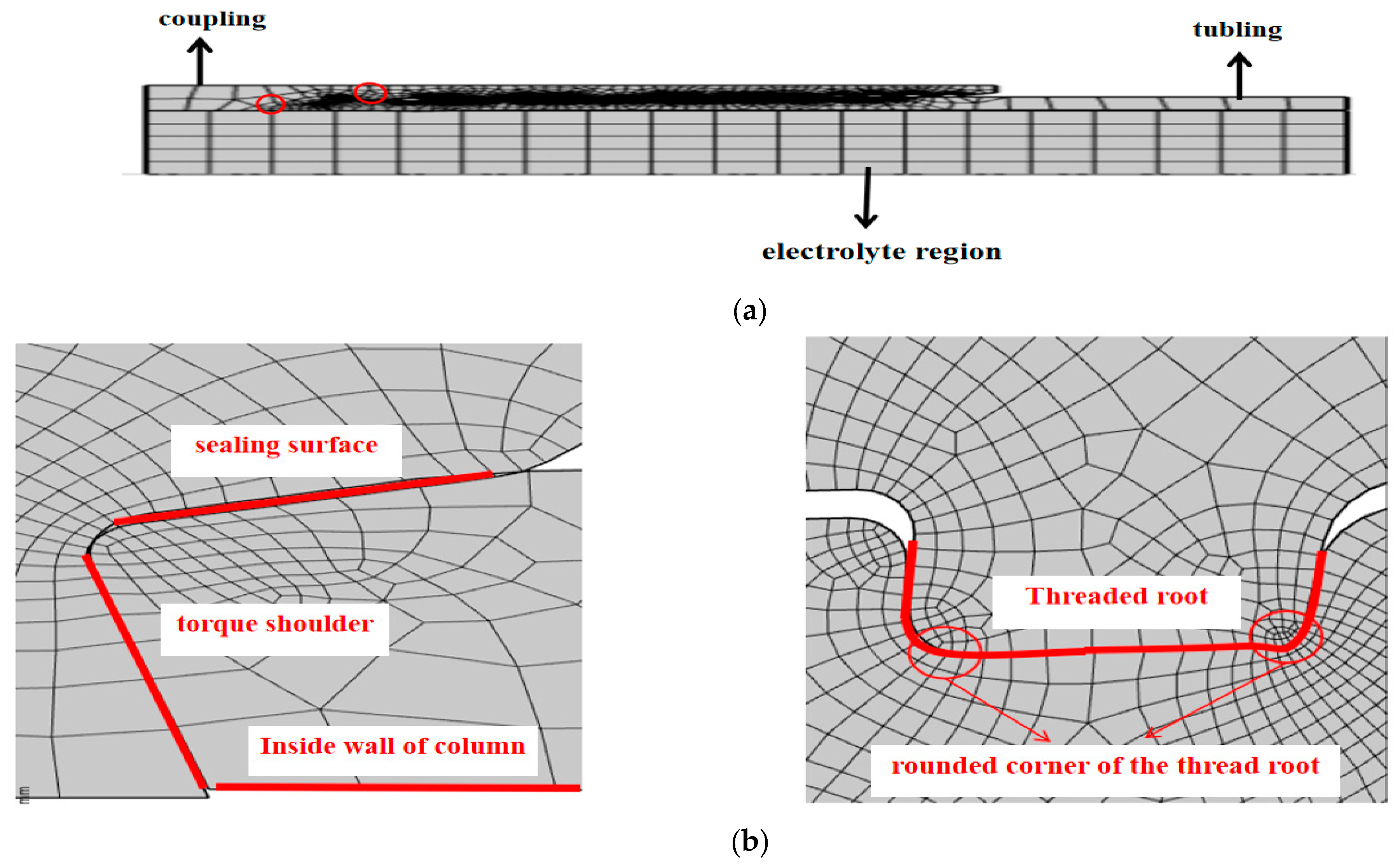
2. Two-Dimensional Axisymmetric Modeling of Premium Connections

In this study, Ф88.9 mm × 6.45 mm P110 taper–taper premium connections were taken as an example [35]. A two-dimensional axisymmetric model of a taper–taper premium connection was established in COMSOL software according to the parameters in Table 1. The finite element model was pre-processed according to the material property parameters in Table 2, and the material properties were set to isotropic elastic–plastic. The sealing surface of premium connections is the main seal, and the torque shoulder is the auxiliary seal. The mesh division of the premium connections is shown in Figure 1.
In the electrochemical simulation, a secondary current distribution physical field was added, the premium connections were set as electrodes, and internal electrode reactions were set up, with the specific parameter settings listed in Table 3.

3. Analysis of Corrosion Results for Premium Connections

In actual working environments, premium connections are subjected to several kinds of loads, such as tensile, compressive, and internal pressure, as well as different environmental factors. Our corrosion model of premium connections was constructed via mechanical analysis and finite element analysis to study the influence of environmental parameters and different internal pressures and tensile strains on the corrosion of premium connections.

3.1. Influence of Environmental Parameters on Corrosion Laws of P110 Premium Connections

3.1.1. Temperature Effect on Corrosion Laws

Figure 2 shows the variation curve of the corrosion rate with temperature. As the temperature increases from 40 °C to 120 °C, the corrosion rate increases from 1.18 mm/a to 2 mm/a. The higher the CO2 partial pressure, the more pronounced the increase in the corrosion rate. The pH value also greatly influences the corrosion rate; as the temperature increases, the electrochemical corrosion reaction accelerates, at the same time affecting the kinetics of FeCO3 generation. The corrosion product film gradually changes from loose to porous. Sensitive temperature points can be avoided on site by controlling CO2 levels.
Temperature’s effect on the CO2 corrosion rate is more complex. In a certain temperature range, the dissolution rate of carbon steel in CO2 solution increases with an increase in temperature; when the carbon steel surface forms a dense film of corrosion products, the dissolution rate of carbon steel in CO2 aqueous solution decreases with an increase in temperature.

3.1.2. Effect of CO2 Partial Pressure on Corrosion Laws

Figure 3 shows the variation curve of the corrosion rate with CO2 partial pressure. The corrosion rate increases nearly linearly with an increase in CO2 partial pressure from 0 to 15 bar, indicating that this is an important factor affecting the corrosion of tubes. The effect of CO2 partial pressure on the corrosion rate when no corrosion product film is on the metal surface has been studied in detail in the literature [36]. The corrosion rate of carbon steel accelerates as the partial pressure of CO2 increases; as the CO2 partial pressure increases, the amount of CO2 dissolved in water increases, the aqueous solution decreases, and the acidity increases, thus increasing the corrosiveness of the solution.

3.1.3. Effect of pH Value on Corrosion Laws

Figure 4 shows the variation curve of the corrosion rate with the pH value. With the pH value increasing from 4 to 6, the corrosion rate shows a decreasing trend. At a low pH value, the concentration of hydrogen ions is higher, oxidizing the metal and making it more susceptible to corrosion. This usually results in faster corrosion rates, which tend to be lower in high-pH environments where the hydrogen ion concentration is reduced and the anodic reaction of the metal is slowed. The higher the CO2 partial pressure, the higher the corrosion rate, the higher the temperature, and the faster the corrosion rate. At a pH value higher than 5, the corrosion rate shows a flat trend.

3.2. Corrosion Thickness Analysis of Premium Connections

Figure 5 shows a corrosion analysis of the premium connections under specific operating conditions with 5 and 10 years of service. The maximum corrosion locations are on the torque shoulder, where the maximum corrosion thickness is 1.29 mm and 3.57 mm; that is, an increased service condition time leads to an accelerated corrosion rate. Major causes of severe corrosion include changes in local flow velocity and flow direction caused by changes in the flow cross-section brought about by the groove structure on the shoulder surface of premium connections.
Figure 6 compares the simulated maximum corrosion location and the real maximum corrosion location. The maximum corrosion location appears on the torque table shoulder; thus, the simulation results and the real situation in the literature are similar [10].

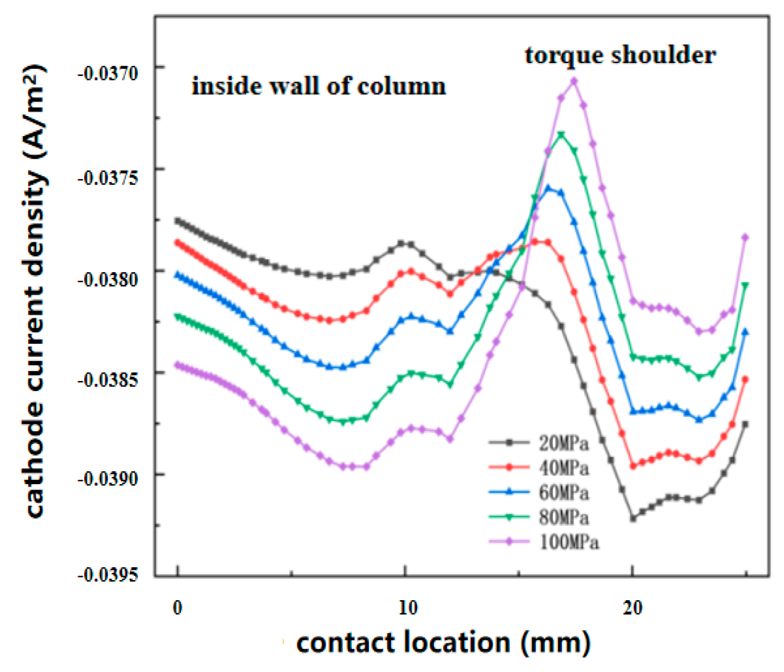
3.3. Anodic/Cathodic Current Density Analysis of Premium Connections

Figure 7 shows the linear distribution of anode current density along the inner wall of the column to the shoulder of the table for different internal pressures. At a lower internal pressure of 20 MPa, the anode current density is lowest on the inner wall of the column and gradually increases along the inner wall of the column to the shoulder of the table, where the anode current density is the highest, reaching 0.0388 A/m2. When the internal pressure increases to 100 MPa, the anode current density on the inner wall of the column increases, reaching a maximum of 0.0387 A/m2, while the anode current density at the shoulder of the torque table shows a negative increasing trend.
Figure 8 shows the linear distribution of the cathode current density along the inner wall of the column to the shoulder of the table for different internal pressures. The cathodic current density on the inner wall of the column reaches its maximum at −0.0378 A/m2 at 20 MPa. As the internal pressure increases, the cathodic current density on the inner wall of the column decreases, while the cathodic current density on the shoulder increases. By combining the two figures, we can see that the corrosion rate on the torque shoulder surface is larger than that on the inner wall of the tubular columns under an internal pressure of 20 MPa, indicating that corrosion damage is more likely to occur at the shoulder than at the inner wall. However, with an increase in internal pressure, the corrosion rate on the inner wall of the column is larger than that on the torque shoulder at 100 MPa, indicating that corrosion damage is more likely to occur at the inner wall than at the torque shoulder.

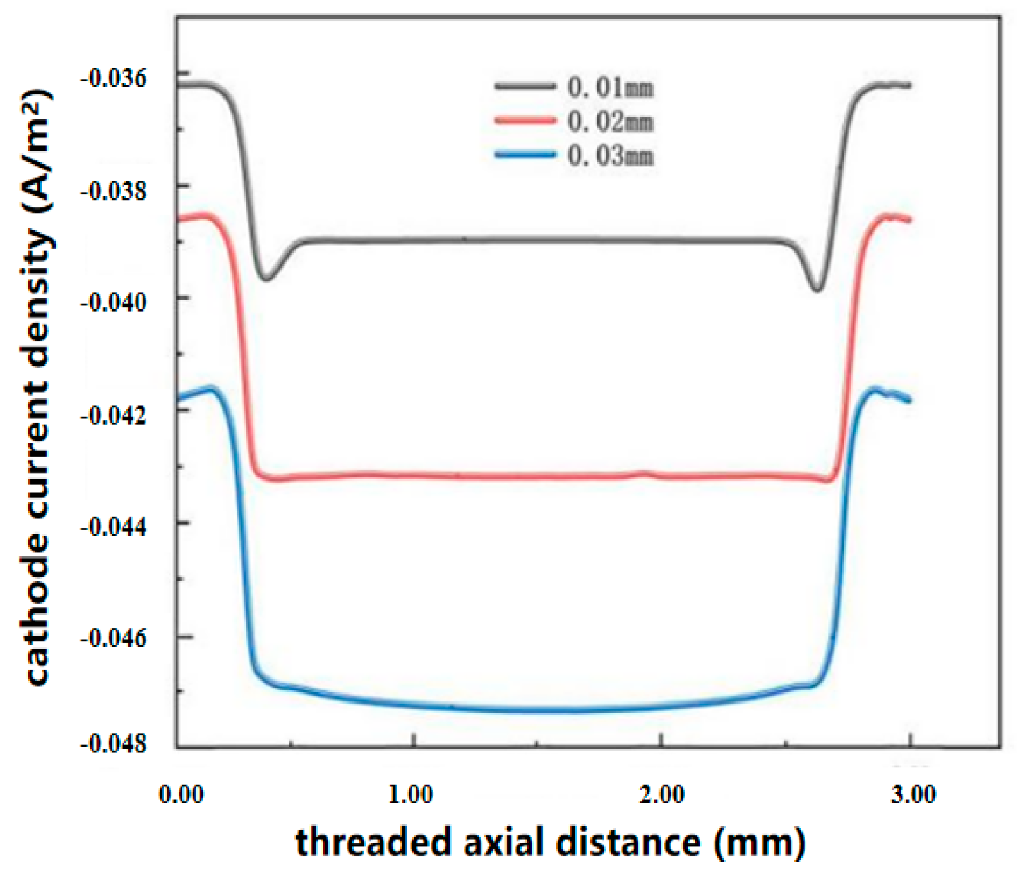
3.4. Premium Connections’ Threaded Anodic/Cathodic Current Density Analysis

Figure 9 shows the linear distribution of the anodic current density over the threads for different tensile strains. The anodic current density along the direction of the threads is constant at 0.038 A/m2 for a tensile strain of 0.01 mm. When the strain increases to 0.02 and 0.03, the anodic current density increases with an almost uniform distribution on the root of the threads, but the most significant increase in current density can be observed at the rounded corners of the root of the threads, where it reaches 0. 056 A/m2 and 0. 058 A/m2.
Figure 10 shows the linearity of the cathodic current density over the threads for different tensile strains. The cathodic current density on the threads is the largest at a tensile strain of 0.01 mm, with a maximum of −0.036 A/m2. The cathodic current density on the threads shows a negative trend as the tensile strain increases, and the inhomogeneity of the cathodic current density becomes more pronounced with an increase in tensile strain. By combining the two figures, we can see that the corrosion rate of the threads becomes larger with increased tensile strain; the corrosion rate at the rounded corner of the thread root is the largest, indicating that it more easily corrodes and takes damage at the rounded corner of the thread root. The reason for this may be the concentration of stress at the rounded corner of the thread root.

3.5. Von Mises Stress and Contact Pressure Cloud Analysis of Premium Connections

Simulation analyses were carried out using a finite element simulation of the premium connections, applying internal pressure loads of 20 MPa, 40 MPa, 60 MPa, 80 MPa, and 100 MPa to the inner wall of the column in the uncorroded and post-corroded buckling states.
Figure 11 shows the von Mises stress clouds for uncorroded premium connections at five internal pressures. The maximum von Mises stresses of the premium connections under different internal pressures are, in order, 600 MPa, 600 MPa, 700 MPa, 700 MPa, and 800 MPa. The cloud diagrams show that when the internal pressure load increases from 20 MPa to 100 MPa, the overall von Mises stresses show an increasing trend, although the increasing values are not very large. In the case of a smaller internal pressure load, the stress at the shoulder is larger but does not exceed the yield strength of the material. With an increase in the internal pressure load, the stress concentration location of the premium connections gradually concentrates from the shoulder partially to the face cover, and the local stress in the premium connections exceeds the yield strength of the material, indicating that the premium connections locally undergo plastic deformation. Neglecting localized regional plastic strain phenomena, the premium connections are structurally complete and well sealed.
Figure 12 shows the von Mises stress clouds for the premium connections in the post-corrosion condition at five internal pressures. The von Mises stress of the post-corrosion condition premium connections is significantly higher than that of the non-corroded premium connections, and the maximum value even reaches 1000 MPa. The cloud diagram shows that the overall von Mises stresses demonstrate an increasing trend when the internal pressure load increases from 20 MPa to 100 MPa. In the case of a smaller internal pressure load, the stress at the shoulder of the table is large, reaching a maximum of 900 MPa, exceeding the yield strength of the material. With an increase in internal pressure, the stress concentration site transitions from the shoulder to the sealing surface, but the maximum value reaches 1000 MPa, still exceeding the yield strength of the material. The premium connections undergo obvious plastic deformation, reducing their sealing performance compared with the uncorroded connections.
The sealing surface of the premium connections is the main seal, and the torque shoulder is the auxiliary seal; thus, to further study the change rule of the premium connection sealing properties before and after corrosion, we must plot the contact pressure pattern of the sealing surfaces before and after corrosion. Figure 13a shows the contact pressure curve of the sealing surface without corrosion under five kinds of internal pressure loads. The maximum contact pressure of the sealing surface shows an increasing trend when the internal pressure increases from 20 MPa to 100 MPa, and the maximum reaches 1100 MPa from 800 MPa. As the internal pressure increases, the contact pressure of the sealing surface increases, improving the sealing performance of the premium connections.
Figure 13b shows the contact pressure curves of the premium connection sealing surfaces after corrosion under five kinds of internal pressure loads. The maximum contact pressure of the sealing surface increases from 650 MPa to 900 MPa when the internal pressure increases from 20 MPa to 100 MPa. At the same time, the contact pressure distribution on the sealing surface is very uneven regardless of whether the premium connections are corroded, and the contact pressure distribution curve on the sealing surface is steeper in both the corroded and uncorroded states. The maximum contact pressure occurs at the end of the premium connections. By comparing the contact pressure curve of the sealing surface before and after corrosion, we can see that the maximum contact pressure after corrosion is obviously reduced compared with that of the connections in the non-corroded condition.

4. Sealing Performance Evaluation Criteria

According to fluid mechanics, a fluid seal can be achieved when the resistance of the fluid medium through the sealing port is greater than the pressure difference between the two sides of the sealing surface (inside and outside of the pipe) [37]. According to this principle, the API (American Petroleum Institute) sealing criterion states that the sealing contact pressure must be greater than the fluid pressure in tubular columns; thus, to maintain the sealing ability of premium connections, their maximum contact pressure after screwing should be greater than the internal pressure. Many studies have concluded that contact length is equally important as contact pressure [38]. Under the premise of ensuring that the sealing surface does not yield, the longer the contact length and the higher the contact pressure, the better the sealing effect.
To quantitatively study the sealing performance of premium connections, researchers have introduced the concept of sealing strength as the evaluation criterion for sealing performance. Sealing strength is the integral of the contact pressure on the sealing surface over the contact length, which can be calculated as
W = 0 l p ( l ) d l ,
where W is the seal strength, P(l) is the contact pressure, and l is the contact length.
In 2004, Murtagian G.R. [37] suggested that of the two indicators, contact pressure and contact length, contact pressure has a greater effect on sealing performance and therefore modified the above equation as follows:
W = 0 l p ( l ) n d l
where n is the correction factor; depending on whether a threaded compound is used or not, n = 1.2 or 1.4.
Furthermore, Murtagian G.R. [37] provides a method for determining the critical sealing strength, Wac, where the sealing of premium connections is effective only if the sealing strength, W, on the sealing surface is greater than Wac.
W a c = B p g a s p a l i g n m
where Wac is the critical seal strength, Pgas is the pressure inside the tube, Patm is the outside air pressure, and m is a factor. With the threaded compound, B = 1.843 × 10⁻³ and m = 1.177; without the threaded compound, B = 0.1036 and m = 0.838
The above analyses are only qualitative comparisons; thus, the following quantitative study is carried out using the sealing criterion. Using the criterion proposed by Murtagian G.R. [37], the seal strength, W, of the premium connections before and after corrosion was calculated according to Equation (2) for five loading conditions at different internal pressures without using a threaded compound in the premium connections (n = 1.4). The critical seal strength, Wac, was calculated using Equation (3), and the results are shown in Table 4 and Table 5, and based on the results in the tables, the comparative histograms are plotted and the results are shown in Figure 14.
Figure 14 shows that the sealing strength of the premium connections increased with an increase in internal pressure under the five internal pressure loads. Furthermore, their sealing strengths before and after corrosion were greater than the critical value, indicating that their sealing performance fulfilled the criterion. However, the sealing strengths of the corroded premium connections were all less than those of the uncorroded connections.
Critical sealing strength refers to the critical value of premium connection seals; the larger the ratio of sealing strength to critical sealing strength, the better the sealing performance. Figure 14 shows that the ratio of sealing strength to critical sealing strength becomes smaller after corrosion in the premium connections, indicating that their sealing performance decreases after corrosion.

5. Conclusions

To analyze the difference between premium connections before and after corrosion, Ф88.9 mm × 6.45 mm P110 taper–taper premium connections were studied using COMSOL software to establish a two-dimensional model, coupled with structural mechanics and a secondary current distribution field. Corrosion in premium connections under different internal pressures (20–100 MPa), different tensile strains, and sealing surface contact pressure distribution laws was analyzed. Finally, the sealing performance of the premium connections was analyzed.
(1)
We studied the influence of environmental factors such as temperature, pH value, and CO2 partial pressure on the corrosion of P110 premium connections in CO2 production wells. The surface CO2 partial pressure most obviously influenced corrosion, and the corrosion rate and downhole time demonstrated a positive linear relationship; the longer the working time, the greater the corrosion depth. When the corrosion system reaches equilibrium, the premium connections’ shoulder electrolyte potential is high, indicating a greater degree of corrosion.
(2)
Under an internal pressure of 20 MPa, the corrosion rate of the torque shoulder was larger than that of the inner wall of the column, indicating that corrosion damage is more likely at the shoulder than at the inner wall of the column. However, with an increase in internal pressure (100 MPa), the corrosion rate of the inner wall of the column was larger than the corrosion rate of the torque shoulder, indicating that corrosion damage is more likely at the inner wall of the column than at the torque shoulder.
(3)
With increased tensile strain, the corrosion rate of the threads became larger. The corrosion rate of the thread root fillet was the largest, indicating that the thread root fillet is more susceptible to corrosion damage; the reason for this may be the stress concentration at the thread root fillet.
(4)
Under five internal pressure loads, the sealing strength of the premium connections increased with an increase in internal pressure. The sealing strength of the premium connections before and after corrosion was greater than the critical value, indicating that their performance fulfilled the criterion. However, the sealing strengths of the premium connections after corrosion were smaller than those of non-corroded connections, indicating that the sealing performance of premium connections decreases after corrosion.

Author Contributions

Writing—original draft, Y.C., P.G., Y.Y. and Y.D. All authors have read and agreed to the published version of the manuscript.

Funding

This research was funded by Y.C.: National Natural Science Foundation of China (52374039), Y.C.: Shaanxi Province Natural Science Basic Research Programme Project (2023-JC-YB-337) and Y.D.: National Natural Science Foundation of China (52274006).

Data Availability Statement

No new data were created or analyzed in this study.

Conflicts of Interest

The authors declare no conflict of interest.

References

  1. Sun, L.; Dou, H.; Li, Z.; Hu, Y.; Hao, X. Assessment of CO2 storage potential and carbon capture utilization and storage prospect in China. J. Energy Inst. 2017, 91, 970–977. [Google Scholar] [CrossRef]
  2. Xiang, Y.; Yuan, Y.; Zhou, P.; Liu, G.; Lyu, W.; Li, M.; Zhang, C.; Zhou, Q.; Zhao, X.; Yan, W. Metal Corrosion in Carbon Capture, Utilization, and Storage: Progress and Challenges. Strateg. Study CAE 2023, 25, 197–208. [Google Scholar] [CrossRef]
  3. Zhang, K.; Sun, Y.; Wang, C.; Ge, H.; Zhua, Y.; Wang, H. Research on CO2 Corrosion and Protection in Carbon Capture, Utilization and Storage. Surf. Technol. 2022, 51, 43–52. [Google Scholar]
  4. Xiao, Z.; Shen, B.; Yang, J.; Yang, K.; Zhang, Y.; Yang, S. Deep Learning Framework for Accurate Static and Dy-namic Prediction of CO2 Enhanced Oil Recovery and Storage Capacity. Processes 2024, 12, 1693. [Google Scholar] [CrossRef]
  5. Nguyen, H.B.T.; Bahzad, M.Y.H.; Leonzio, G. Economic and Environmental Optimization of a CCUS Supply Chain in Germany. Processes 2024, 12, 1575. [Google Scholar] [CrossRef]
  6. Xing, L.R.; Wu, Z.W.; Zhang, R.Y. Development status and prospect analysis of CCUS industry. Int. Pet. Econ. 2021, 29, 99–105. [Google Scholar]
  7. de Visser, E.; Hendriks, C.; Barrio, M.; Mølnvik, M.J.; de Koeijer, G.; Liljemark, S.; Le Gallo, Y. Dynamis CO2 quality recommendations. Int. Greenh. Gas Control 2008, 2, 478. [Google Scholar] [CrossRef]
  8. Halseid, M.; Dugstad, A.; Morland, B. Corrosion and bulk phase reactions in CO2 transport pipelines with impurities: Review of recent published studies. Energy Procedia 2014, 63, 2557. [Google Scholar] [CrossRef]
  9. Liu, Z.; Yin, P.; Mou, C.; Wang, S.; Shang, L.; Cao, X.; Zhang, G.; Xue, Q. Unraveling the corrosion behavior and mechanism of DL-C film on the inner surface of N80 lengthy pipeline in CO2-H2S-Cl environment. Surf. Coat. Technol. 2024, 494 Pt 1, 131350. [Google Scholar] [CrossRef]
  10. Lv, S.L.; Song, W.W.; Yang, X.T.; Peng, J.X.; Han, Y.; Zhao, G.X.; Lv, X.H.; Guo, Z.D.; Wen, Y.X.; Zhu, L.L. Corrosion Causes of Premium Connection S13Cr Tubing in a Well. Corros. Prot. 2015, 36, 76–80+83. [Google Scholar]
  11. Lv, S.L.; Luo, F.Q.; Xiang, M.; Zhou, J.; Chang, Z.; Qin, H.; Fu, D. Cases Analysis on Corrosion for API Tubing. Corros. Sci. Prot. Technol. 2008, 20, 388–390. [Google Scholar]
  12. Wang, B.D.; Duan, Q.Q.; Liu, X.B.; Yu, Y.; Wu, K. Stress analysis and failure assessment on threaded connection between N80 tubing and collar. J. Saf. Sci. Technol. 2017, 13, 56–60. [Google Scholar]
  13. Yu, H.; Cheng, X.T.; Lian, Z.H.; Ding, L.; Wang, H.; Chen, Y. Comprehensive Performance Evaluation of Sealing and Safety of Premium Tubing Connection. Lubr. Eng. 2023, 48, 191–199. [Google Scholar]
  14. Xu, Z.Q.; Wang, B.B.; Yan, Y.F.; Yan, X.; Gai, Y. Integrity Evaluation Analysis of Casing Premium Connection. Press. Vessel. Technol. 2019, 36, 35–42+13. [Google Scholar]
  15. Shen, Z.X.; Li, H.J.; Zhao, G.; Wang, H.M.; Liu, J.D.; Yan, Y.; Wang, J.J. Discussion on Evaluation Methods for Sealing Test of Tubing and Casing Premium Connection. Pet. Tubul. Goods Instrum. 2024, 1–5. [Google Scholar] [CrossRef]
  16. Dong, G.Y.; Sun, J.A.; Gao, Z. Numerical simulation analysis of sealing performance of premium connection. Baosteel Technol. 2023, 61–65. [Google Scholar] [CrossRef]
  17. Wang, C.; Dan, H.; Dai, H.Y.; Gao, L.X. Comparative analysis of sealing performance between tapered/tapered and spherical/tapered structures of special threaded joint of oil casing. Mech. Sci. Technol. Aerosp. Eng. 2024, 1–8. [Google Scholar] [CrossRef]
  18. Dou, Y.H.; Qiang, N.; Yu, Y.; Cao, Y.P. Element Analysis of Make-up Torque of Special Threaded Tubing oints. Mech. Electr. Eng. Technol. 2022, 51, 56–59. [Google Scholar]
  19. Guoxi, H.; Qing, Z.; Kexi, L.; Leng, L.; Zhao, S. Corrosion mechanism of high temperature and O2 c-ontent in steamed CO2/O2/SO2 system and failure behavior of 20G steel on steam-injection pipelines. Process Saf. Environ. Prot. 2022, 163, 528–542. [Google Scholar]
  20. Yang, B.; Xu, H.; Xiang, S.; Zhang, Z.; Su, K.; Yang, Y. Effects of Make-Up Torque on the Sealability of Sphere-Type Premium Connection for Tubing and Casing Strings. Processes 2023, 11, 256. [Google Scholar] [CrossRef]
  21. Yu, Y.; Qu, Z.; Dou, Y.; Cao, Y. Analysis of Energy Dissipation on the Sealing Sur-face of Premium Connection Based on a Microslip Shear Layer Model. Energies 2022, 15, 8400. [Google Scholar] [CrossRef]
  22. Song, W.; Zhou, Y.; Wu, Y.; Yang, Y.; Ye, S. A Study on Sealing Performance of UGS Well Casing Thread Under High-speed Injection-production. J. Southwest Pet. Univ. (Sci. Technol. Ed.) 2024, 46, 170–178. [Google Scholar]
  23. Liang, H.; Fan, H.; Ren, X. Simulation Study on Sealing Performance of Special Threaded oints of Pipe String under Action of Additional Bending Moment. J. Southwest Pet. Univ. (Sci. Technol. Ed.) 2024, 1–10. Available online: http://kns.cnki.net/kcms/detail/61.1435.TE.20240515.1012.002.html (accessed on 29 October 2024).
  24. Yang, D.M.; Li, Y.G.; Zhang, J.J.; Liang, G.S. Tubing Corrosion Analysis and Control Measures in Dalaoba Gas Field. Pet. Drill. Tech. 2011, 39, 82–85. [Google Scholar]
  25. Li, Z. Research on Corrosion Mechanism and Control Technology of Production and Transportation System in Taha Oil and Gas Field. China Petroleum and Chemical Corporation Northwest Oilfield Branch. Available online: www.cnki.net (accessed on 29 October 2024).
  26. Lv, S.L.; Zhao, G.X.; Wang, X.H.; Yan, M.L.; Fu, D.M.; Zhang, J.X. Analysis of Downhole Premium Connection Tubing Corrosion. Corros. Prot. 2005, 4, 179–181. [Google Scholar]
  27. Lv, S.L.; Peng, J.X.; Gao, W.X.; Yang, S.B.; Geng, H.L.; Wang, P.; Liu, W.H.; Zhu, L.J. Causes Analysis on Corrosion Barrier Ring Squeezed out in Premium Connection Tubing during Pressure Test. Drill. Prod. Technol. 2021, 44, 123–126. [Google Scholar]
  28. Wang, X.H.; Yi, C.X.; Wang, D. Influence of compressive stress on corrosion of premium connection casing material. J. China Univ. Pet. (Ed. Nat. Sci.) 2013, 37, 119–123+129. [Google Scholar]
  29. Li, Y.H.; Du, N.; Liu, M. Failure Analysis of FE-HP1-13Cr Steel Tubing. Total Corros. Control 2017, 31, 71–75+86. [Google Scholar]
  30. Du, J.N.; Yang, C.Y.; Jin, W.; Li, Y.H. Failure Analysis of Corrosion Perforation of Manifold Pipeline in an Oilfield. Total Corros. Control 2017, 31, 39–42. [Google Scholar]
  31. Zhao, J.; Bai, X.; Qu, T.; Li, D.; Liu, W.; Wei, Z.; Xiaolong, L. Corrosion Failure Analysis of a S135 Drill Pipe. J. Fail. Anal. Prev. 2024, 24, 368–379. [Google Scholar] [CrossRef]
  32. Zhang, H.; Wang, G.; Zhao, J.; Deng, B.; Zhang, L. Failure Analysis of Tripping Tubing in an Oilfield. J. Fail. Anal. Prev. 2022, 22, 1268–1275. [Google Scholar] [CrossRef]
  33. Malyshev, V.; Gelfgat, M.; Scherbakov, A.; Alkhimenko, A. Protection enhancing of threaded conne-ctions of light-alloy drill pipes against contact corrosion. E3S Web Conf. 2021, 225, 03003. [Google Scholar] [CrossRef]
  34. Yan, H.; Zheng, C.L.; Li, H.Z.; Li, Y.F.; Zhu, D.J. Analysis of Corrosion Behavior on External Surf-Ace of 110S Tubing. Mater. Sci. Forum 2020, 930, 1242–1250. [Google Scholar]
  35. SY/T 6262-2008; Recommended Practices for Tubing Selection. Petroleum Industry Press: Beijing, China, 2008.
  36. Zhang, Z.; Ding, C.; Liu, W.; Zhao, Y. Study on corrosion of Cr-containing steel under diff-erent CO2 partial pressures at high temperatures. Geoenergy Sci. Eng. 2024, 243, 213365. [Google Scholar] [CrossRef]
  37. Murtagian, G.R.; Fanelli, V.; Villasante, J.A.; Johnson, D.H.; Ernst, H.A. Seal-ability of stationary metal-to-metal seals. J. Tribolo-Gy 2004, 126, 591–596. [Google Scholar] [CrossRef]
  38. Xie, R.; Rong, F. Desseint Methodology for Reliabilitybased Design and Assessment of Tubular Connection Sealabilityin HPHT Wells. 2014. Available online: https://www.researchgate.net/publication/307957467 (accessed on 29 October 2024).
Figure 1. Schematic diagram of finite element model and meshing for premium connections. (a) Two-dimensional axisymmetric modeling of premium connections. (b) Threaded root, sealing surfaces, and torque shoulder grid refinement.
Processes 12 02680 g001
Figure 2. Transformation curve of corrosion rate with temperature.
Processes 12 02680 g002
Figure 3. Variation curve of corrosion rate with CO2 partial pressure.
Processes 12 02680 g003
Figure 4. Variation curve of corrosion rate with pH value.
Processes 12 02680 g004
Figure 5. Corrosion thickness of premium connections. (a) 5 years. (b) 10 years.
Processes 12 02680 g005
Figure 6. Comparison of simulated and real maximum corrosion locations of premium connections. (a) 5 years. (b) 10 years.
Processes 12 02680 g006
Figure 7. Anode current density distribution along inner wall direction of tube column at different internal pressures.
Processes 12 02680 g007
Figure 8. Cathode current density distribution along inner wall direction of tube column at different internal pressures.
Processes 12 02680 g008
Figure 9. Anodic current density distribution along direction of thread under different tensile loads.
Processes 12 02680 g009
Figure 10. Cathode current density distribution along direction of thread under different tensile loads.
Processes 12 02680 g010
Figure 11. Von Mises equivalent stress distribution under different internal pressure loads (before corrosion). (a) 20 MPa; (b) 40 MPa; (c) 60 MPa; (d) 80 MPa; (e) 100 MPa.
Processes 12 02680 g011
Figure 12. Von Mises equivalent stress distribution under different internal pressure loads (after corrosion). (a) 20 MPa; (b) 40 MPa; (c) 60 MPa; (d) 80 MPa; (e) 100 MPa.
Processes 12 02680 g012
Figure 13. Contact pressure distribution curve of sealing surface under different internal pressure loads. (a) Before corrosion; (b) After corrosion.
Processes 12 02680 g013
Figure 14. Comparison of seal strength and critical seal strength at different pressures (n = 1.4).
Processes 12 02680 g014
Table 1. Parameters of taper–taper premium connections.
Bearing Surface Angle/°Tracking Surface Angle/°Shoulder Angle/°Thread Distance/mmThread TaperSealing Surface Taper
−3°10°−10°4.2341/161/2
Table 2. Performance parameters of taper–taper premium connection material.
SteelsElastic Modulus/GPaPoisson’s RatioYield Strength/MPaFriction Coefficient
P1102100.37580.1
Table 3. Parameters required for corrosion simulation of premium connections.
ParametersNumerical
Reference exchange current density for H+ reduction0.05 A/m2
Reference exchange current density for H2CO3 reduction0.06 A/m2
Reference exchange current density for water reduction3 × 10−5 A/m2
Reference exchange current density for Fe oxidation1 A/m2
Tafel slope for H+ reduction0.118 V
Tafel slope for H2CO3 reduction0.12 V
Tafel slope for water reduction0.118 V
Tafel slope for Fe oxidation0.04 V
Table 4. Critical seal strength at different pressures (n = 1.4).
Stress/MPaCritical Sealing Strength/(m·MPa)
200.847
401.515
602.128
802.708
1003.265
Table 5. Contact properties of premium connections at different pressures.
Stress/MPaAverage Contact Pressure/MPaEffective Contact Length/mmSealing Strength/(m·MPa)
Before CorrosionAfter CorrosionBefore CorrosionAfter CorrosionBefore CorrosionAfter Corrosion
20716.41572.540.400.353.92.5
40872.54690.780.440.385.73.5
60939.45710.410.520.407.53.9
801030.78803.780.560.419.24.7
1001134.10894.100.600.5011.36.7
Disclaimer/Publisher’s Note: The statements, opinions and data contained in all publications are solely those of the individual author(s) and contributor(s) and not of MDPI and/or the editor(s). MDPI and/or the editor(s) disclaim responsibility for any injury to people or property resulting from any ideas, methods, instructions or products referred to in the content.

