Article

A Prediction Method for Calculating Fracturing Initiation Pressure Considering the Modification of Rock Mechanical Parameters After CO2 Treatment

1
National Key Laboratory of Continental Shale Oil, Northeast Petroleum University, Daqing 163318, China
2
Daqing Oilfield Production Technology Institute, Daqing Oilfield Limited Company, Daqing 163318, China
3
Daqing Oilfield No. 2 Oil Production Company, Daqing Oilfield Limited Company, Daqing 163318, China
4
School of Environment, Liaoning University, Shenyang 110036, China
*
Authors to whom correspondence should be addressed.
Processes 2024, 12(11), 2525; https://doi.org/10.3390/pr12112525
Submission received: 14 October 2024 / Revised: 7 November 2024 / Accepted: 9 November 2024 / Published: 13 November 2024
(This article belongs to the Topic Exploitation and Underground Storage of Oil and Gas)

Abstract

:
The establishment of a more realistic CO2 fracturing model serves to elucidate the intricate mechanisms underlying CO2 fracturing transformation. Additionally, it furnishes a foundational framework for devising comprehensive fracturing construction plans. However, current research has neglected to consider the influence of CO2 on rock properties during CO2 fracturing, resulting in an inability to precisely replicate the alterations in the reservoir post-CO2 injection into the formation. This disparity from the actual conditions poses a substantial limitation to the application and advancement of CO2 fracturing technology. This work integrates variations in the physical parameters of rocks after complete contact and reaction with CO2 into the numerical model of crack propagation. This comprehensive approach fully acknowledges the impact of pre-CO2 exposure on the mechanical parameters of reservoir rocks. Consequently, it authentically restores the reservoir state following CO2 injection, ensuring a more accurate representation of the post-fracturing conditions. In comparison with conventional numerical simulation methods, the approach outlined in this paper yields a reduction in the error associated with predicting fracturing pressure by 9.8%.

1. Introduction

In recent years, the escalating global demand for energy has propelled the extensive exploration and utilization of unconventional oil and gas resources. Notably, unconventional reservoirs are characterized by lower permeability [1,2,3,4]. Before formal extraction, reservoir transformation is often a prerequisite, and CO2 fracturing stands out as a commonly employed method for such transformation [5,6,7]. In contrast to conventional fracturing methods, CO2 fracturing demonstrates superior environmental friendliness. This method not only conserves substantial water resources but also facilitates CO2 storage [8,9,10], thereby contributing to a reduction in greenhouse gas content. Furthermore, owing to the low viscosity and exceptional fluidity of CO2, it possesses the capability to effectively penetrate and open micropores. Consequently, the fracturing process entails a lower initiation pressure, simplifying the formation of intricate fracture networks [11,12,13]. Pre-CO2 fracturing can reduce the initiation difficulty of rock fracturing, thereby enhancing the effectiveness of hydraulic fracturing treatment. While the anticipated environmental and efficacy advantages of this technology are noteworthy, practical applications still encounter certain issues and challenges that necessitate further in-depth research [14,15,16].

1.1. Experimental Study on CO2 Fracturing

CO2 fracturing research is usually divided into two methods, namely experimental methods and numerical simulation methods [17,18,19]. In CO2 experimental research, Ishida et al. [20] investigated the differences in fracture morphology and initiation pressure between liquid CO2 and supercritical CO2 fracturing in granite. Kizaki et al. [21] found through granite supercritical CO2 and hydraulic fracturing experiments that compared to simple vertical fractures generated by water fracturing, the fractures generated by supercritical CO2 fracturing are more complex. Zhang et al. [22] studied the initiation and propagation laws of CO2 fracturing fractures in shale and pointed out that the degree of bedding development has a significant impact on the complexity of CO2 fracturing fractures. Bennour et al. [23] studied the differences in crack propagation when shale is fractured with water, oil, and liquid CO2, and pointed out that hydraulic fracturing tends to produce Type I cracks, while water and liquid CO2 fracturing are prone to producing Type II cracks. Zou et al. [24] studied the crack propagation law of supercritical CO2 fracturing in layered dense sandstone and pointed out that even under high-level, stress-difference conditions, supercritical CO2 can promote the opening and shear fracture of bedding and natural fractures, thereby forming a complex fracture network. In CO2 experimental research, researchers tend to focus more on true triaxial CO2 fracturing experiments, which are actually the result of multiple-factor coupling. Through this experiment, CO2 fracturing cannot be analyzed from the mechanism level. This article analyzes the effect of CO2 on rocks from the perspective of basic mechanical experiments on rocks treated with CO2 and deeply explores the evolution law of rock mechanics after CO2 contact with rocks.

1.2. Numerical Study on CO2 Fracturing

In a numerical simulation study of CO2 fracturing, Yan et al. [25] considered the influence of CO2 phase change and divided the supercritical CO2 fracturing process into the supercritical CO2 fracturing stage and the CO2 phase change-induced fracturing stage. Based on the extended finite element method, a fluid–solid coupling model for the supercritical CO2 fracturing stage was established. He et al. [26] established a three-dimensional dynamic model to study the expansion of CO2 fracturing fractures. Research has found that the higher the reservoir temperature, the lower the initial in situ stress, and the longer and wider the cracks. Zhang et al. [27] conducted numerical studies on CO2 fracturing using COMSOL software, and the results showed that CO2 fracturing produces a rougher fracturing surface, especially for sandstone samples with a large number of large pores. Based on the above, it can be found that the current numerical simulation research of CO2 fracturing mainly focuses on the differences introduced by the properties of CO2 itself to the fracturing process [28]. Few researchers have paid attention to the impact of CO2 on the properties of reservoir rocks, especially for pre-CO2 fracturing [29]. The pre-CO2 process not only replenishes the formation energy, but also affects the mechanical properties of reservoir rocks. Ignoring its influence will inevitably affect the numerical simulation results and cause significant errors, affect construction design, and cause engineering losses [30,31,32].
In summary, there are still shortcomings in the modification testing of rock mechanical properties using CO2 in current CO2 experimental research. However, in CO2 numerical simulation research, the modification effect of CO2 on rocks is often overlooked, and it is impossible to accurately reproduce the changes in the reservoir after CO2 injection into the formation [33,34]. To address these issues, this article focuses on pre-CO2 fracturing technology, which allows for full contact and reaction between rocks and CO2, followed by mechanical experiments to quantify the impact of CO2 on the mechanical properties of rocks, and analyzes the underlying mechanisms of CO2 fracturing. At the same time, the experimental results are used to establish a pre-CO2 fracturing simulation with modified mechanical parameters. This model fully considers the influence of pre-CO2 fracturing on the mechanical parameters of reservoir rocks, accurately restores the reservoir state after CO2 injection, and provides a reference for CO2 fracturing construction design.

2. Evolution of Rock Mechanical Properties Under CO2 Action

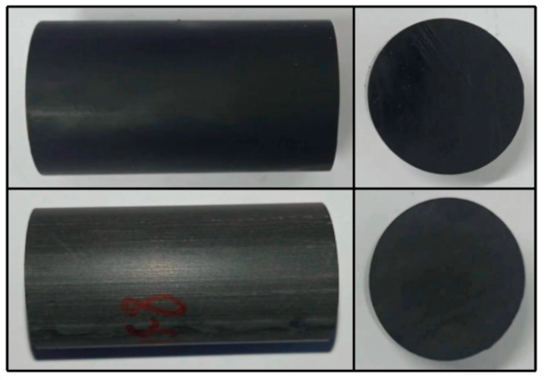
2.1. Experimental Sample and Design

2.1.1. Experimental Sample

The experimental sample of this study is shale, extracted from the Gulong shale oil field in Daqing, China. The vertical in situ stress is 50 MPa, the minimum in situ stress is 40 MPa, the maximum in situ stress is 55 MPa, the formation stress is 25 MPa, and the reservoir temperature is 110 °C. It presents obvious hard brittleness, and the rock is relatively dense with no obvious cracks on the surface. To maintain the same initial state of the rock, the experimental samples in this article are all cut from the same rock. The specific samples can be seen in Figure 1.

2.1.2. Experimental Design

For hydraulic fracturing research, key mechanical parameters include the elastic modulus, Poisson’s ratio, and tensile strength [35]. In this study, the elastic modulus and Poisson’s ratio were determined through triaxial compression tests, while tensile strength was measured using splitting tests. The experiments were conducted with a TAW-2000 microcomputer-controlled electro-hydraulic servo rock triaxial testing machine, which, along with interchangeable molds, enabled both triaxial compression and splitting tests. Permeability measurements were performed using a PDP-200 permeability tester.
The experimental process can be seen in Figure 2. The rock samples were firstly dried at 110 °C for 8 h to remove the influence of bound water inside the rock. Subsequently, the rock core holder was placed in a vacuum for 48 h and immersed in shale oil at 110 °C for 72 h to reach a saturated oil state, restoring the reservoir rock to its true state before extraction. To compare the changes in rock mechanical parameters before and after the influence of CO2 and highlight the effect of CO2 on rock modification, this study set up a control group experiment to test the saturated oil state and the mechanical properties of CO2-modified rock samples. The CO2-modified rock samples were obtained by further processing the saturated oil rock samples. The saturated oil rock samples were placed in a sealed reaction vessel, and CO2 was injected into the reaction vessel at a temperature of 110 °C. The pressure inside the reaction vessel was maintained at 40 MPa, keeping CO2 in a supercritical state for 30 min. At the end of the reaction period, the pressure was released, and the rock sample was removed to obtain the CO2-modified specimen. Finally, permeability tests, triaxial compression tests, and splitting tests were conducted on the above rock samples, with the triaxial compression test set at a confining pressure of 45 MPa, consistent with the minimum horizontal principal stress of the reservoir.

2.2. Analysis of Experimental Results

The results or data from the triaxial compression and splitting experiments were processed to obtain the elastic modulus, Poisson’s ratio, and tensile strength, as presented in Table 1. The rock samples after the experiment are shown in Figure 3 and Figure 4. The following will analyze the parameters of the elastic modulus, Poisson’s ratio, and tensile strength.

2.2.1. The Influence of CO2 on the Rocks’ Elastic Modulus

Figure 5 shows the comparison of the rocks’ elastic modulus before and after CO2 modification. It can be seen from this figure that CO2 has a weakening effect on the rocks’ elastic modulus. Following CO2 modification, the reservoir’s elastic modulus decreased from 21.63 GPa to 18.93 GPa, representing a reduction of 12.5%.
The change in the elastic modulus can be explained by the theory of damage mechanics, in which damage variables are usually used to quantify internal damage to rocks. The most common definition method for damage variables is the Rabotnov damage variable [36]:
D = 1 A ¯ A
where A ¯ is the effective bearing area, m2; A is the total bearing area, which is a fixed value related to the phase state, m2; D is the damage variable.
When the damage variable D is 1, the effective bearing area of the rock is equal to the total bearing area, and no damage occurs inside the rock. When the damage variable D is 0, the effective bearing area of the rock is 0, and the rock is completely destroyed.
Supercritical CO2 (SC-CO2) has extremely strong fluidity. Under high pressure, CO2 will invade the interior of rocks. During the invasion process, it will inevitably damage the internal structure of the rocks and dissolve the minerals inside the rocks, causing the micropores to open and the effective bearing area to decrease. Ultimately, the rocks will be damaged and the damage variable will increase [37]. According to the assumption of strain equivalence, the relationship between the effective stress and the damage variable is as follows:
σ ¯ = σ 1 D
where σ ¯ is the effective stress, Pa. According to the definition of the elastic modulus, Equation (3) can be obtained:
E = σ ε
Equations (2) and (3) can be combined as follows:
E = E 0 ( 1 D )
where E is the elastic modulus of the rock after damage, Pa; E0 is the undamaged elastic modulus, Pa.
When SC-CO2 invades the interior of the rock, the rock undergoes damage, and the damage variable D increases. It can be inferred from Equation (4) that the elastic modulus of the sample after SC-CO2 treatment should decrease, which is consistent with the experimental results in this paper.

2.2.2. The Influence of CO2 on the Rocks’ Poisson’s Ratio

Figure 6 shows the comparison of the rocks’ Poisson’s ratio before and after CO2 modification. The rocks’ Poisson’s ratio after CO2 treatment has a downward trend, decreasing from 0.195 to 0.172, with a decrease of 11.8%.
The reasons for the decrease in Poisson’s ratio can be explained from two aspects. On the one hand, CO2 has a certain dissolution effect, especially for clay minerals. Shale contains a large amount of clay minerals. When CO2 enters the interior of the rock, dissolution occurs, and the clay content inside the rock decreases, leading to an increase in brittleness and a corresponding decrease in the overall Poisson’s ratio. On the other hand, after CO2 invades the interior of the rock, it expands due to dissolution and capillary forces. In triaxial compression experiments, the internal pores of the rock are preferentially compressed when subjected to axial compression, and radial strain is less likely to occur when the pores are closed. The Poisson effect weakens and Poisson’s ratio decreases. The synergistic effect of the above two mechanisms ultimately leads to a decrease in the Poisson’s ratio of shale after CO2 intrusion, which is consistent with the experimental results.

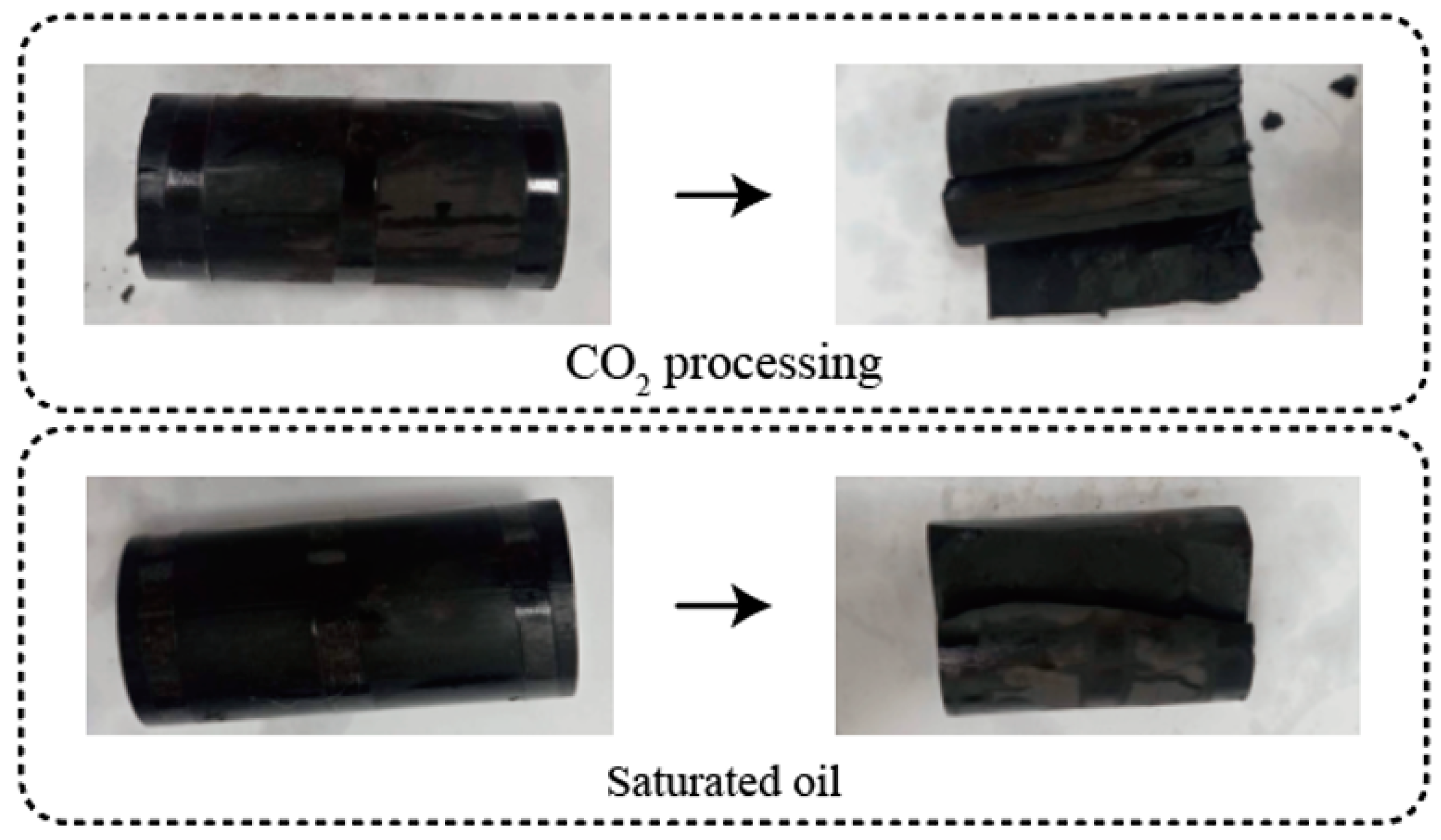
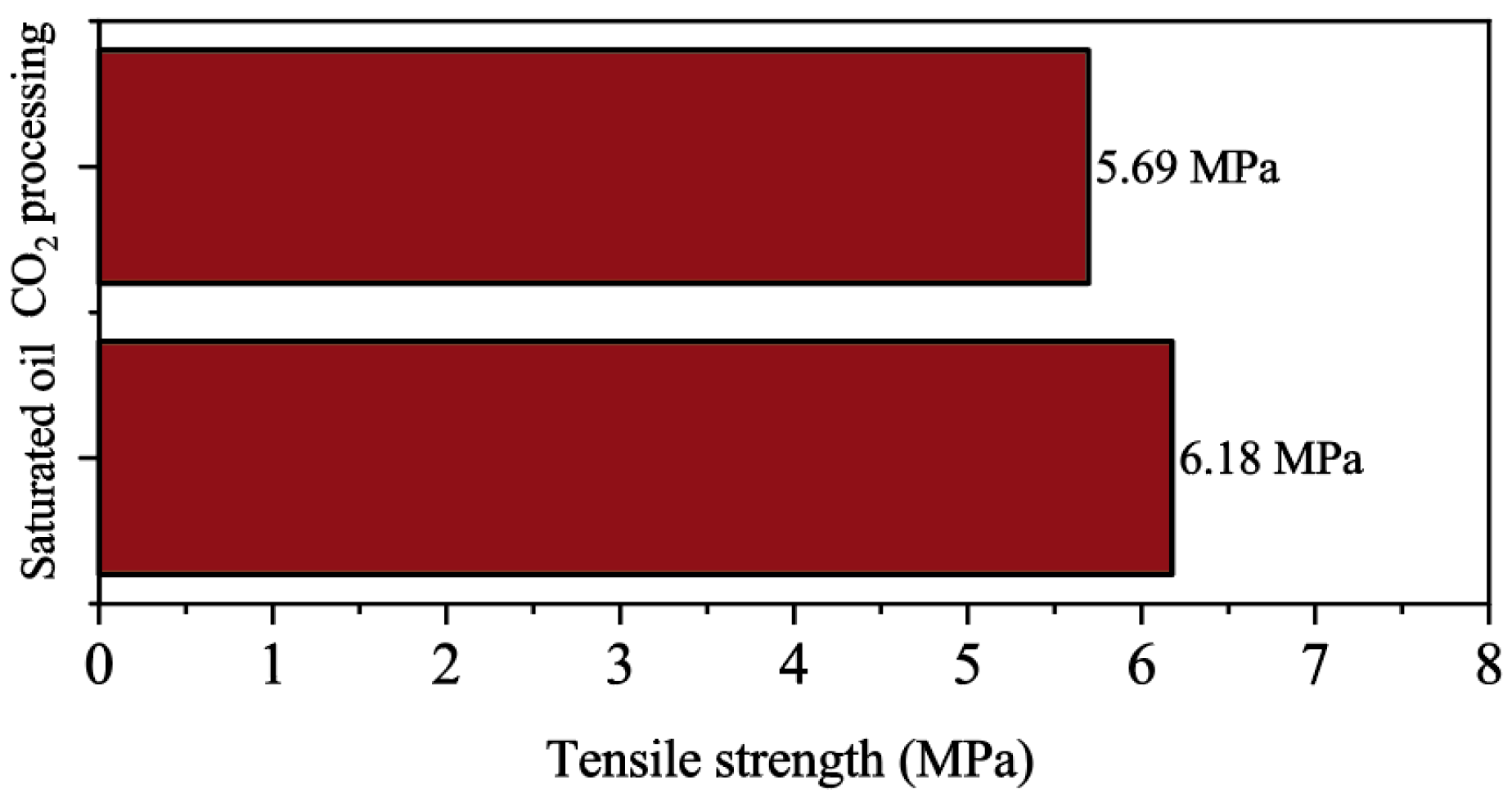
2.2.3. The Influence of CO2 on Rock Tensile Strength

Figure 7 shows the comparison of the rocks’ tensile strength before and after CO2 modification. It can be seen from this figure that CO2 has a weakening effect on the rocks’ tensile strength. After CO2 modification, the reservoir’s tensile strength decreased from 6.18 MPa to 5.69 MPa, which is a decrease of 7.9%.
The dissolution effect of CO2 and the damage to the internal structure of the rocks during transport and flow can both reduce the bonding area of rocks, leading to a decrease in bonding strength. When subjected to tensile stress, fracturing is more likely to occur, and the specific mechanical parameters are manifested as a decrease in tensile strength.

2.2.4. The Influence of CO2 on Rock Permeability

Figure 8 shows the comparison of permeability between shale and supercritical CO2 under saturated oil conditions. From this figure, it can be seen that after shale is soaked in supercritical CO2, the permeability increases from 0.87 mD to 2.43 mD, which is an increase of nearly 180%. Permeability is a quantification of the connectivity of internal pores in rocks. The entry of supercritical CO2 into rock pores will destroy the original pore structure, and the dissolution effect of CO2 will expand the original pores, causing an increase in the volume of connected channels. The macroscopic parameter is an increase in permeability. The findings of this study are highly consistent with those reported in the existing literature [38].

3. Numerical Simulation of Pre-CO2 Fracturing

3.1. Numerical Implementation Methods

In previous CO2 studies, the changes in the mechanical properties of reservoir rocks under CO2 action were usually not considered, resulting in significant errors in numerical simulation results. In this paper, the changes in rock mechanical properties were fully considered in the numerical simulation study.
The numerical simulation data in this article come from a fractured shale oil reservoir well in the Gulong area of Daqing, China. The fracturing of the well is divided into two steps. Firstly, 75 m3 of CO2 is injected into the well at a pressure of 40 MPa within 30 min, and CO2 pre-fracturing is carried out before fracturing. Then, slippery water is used to perform hydraulic fracturing on the reservoir. The numerical simulation part simulates the input parameters based on the actual situation of the well and verifies the numerical simulation results using the fracturing results of the well. Therefore, the numerical simulation part of this article reproduces the construction process and is designed according to the following steps:
Step 1: In situ stress balance, restoring the initial stress state of the reservoir.
Step 2: Pre-injection of CO2, in which CO2 is continuously injected into the formation at a constant pressure of 40 MPa for 30 min to calculate the injected formation pressure.
Step 3: The evolution of rock mechanical properties under the action of CO2. In this step, the range of CO2-modified reservoirs is calculated by the CO2 injection rate. The rock mechanical properties within this range are uniformly modified to the CO2-modified reservoir rock mechanical properties obtained in this experiment. If the rock mechanical parameters are not within this range, the mechanical properties of the saturated oil rock samples obtained in the experiment are assigned.
Step 4: Slippery water fracturing simulation, in which hydraulic fracturing numerical simulation is performed to obtain the initiation pressure.

3.2. Modeling

3.2.1. Seepage Control Equation

The flow of CO2 into the reservoir during the injection process is calculated using Darcy’s law [39]:
v = k η d φ d l
where v is the seepage velocity, m/s; k is the rock permeability, mD; η is the fluid viscosity, mPa·s; φ is the flow force, MPa; and l is the distance between the two stages of seepage, m.

3.2.2. Rock Constitutive Equation

The constitutive equation of the rock matrix is mainly based on elasticity and calculated using the generalized Hooke’s law. The specific equations are as follows (6)–(9):
σ = D el ε el
D el = λ + 2 G λ λ 0 0 0 λ λ + 2 G λ 0 0 0 λ λ λ + 2 G 0 0 0 0 0 0 G 0 0 0 0 0 0 G 0 0 0 0 0 0 G
G = E 2 ( 1 + μ )
λ = E μ ( 1 + μ ) ( 1 2 μ )
where σ is the total stress, Pa; ε el is the total elastic strain, dimensionless; D el is the elastic tensor, Pa; λ is the Lame constant, Pa; G is the shear model, Pa; E is the elastic modulus, Pa; and μ is the initial Poisson’s ratio.

3.2.3. Fracture Propagation Equation

The fracture initiation simulation method in this article uses the extended finite element method (XFEM). The crack adopts a traction separation mode, and the initial damage and damage evolution of the element are linear elastic characteristics. The traction separation behavior can be described by Equation (10):
t N = E ε n
where tN is the traction force, Pa; and εn is the separation displacement, m.
In the calculation of initiation pressure, the maximum nominal principal stress criterion (MAXS) is used as the fracture criterion:
f = max { t n t n 0 , t s t s 0 , t t t t 0 }
where tn is the normal stress on the possible crack surface, Pa; ts and tt are the tangential nominal stress on the crack surface, Pa; t n 0 , t s 0 , and t t 0 are the maximum strength of rocks in three directions, Pa, among which t n 0 is the tensile strength; <> is the Macaulay parentheses, which indicate that a pure compressive stress state will not cause damage. Equation (11) indicates that rock damage occurs when the stress ratio in one of the three directions reaches 1.
The damage scalar Dn represents the overall damage of the material. When the initial value of the damage scalar is 0, the rock undergoes damage. As the loading continues, Dn gradually evolves from 0 to 1. The stress component of traction separation is affected by the following damages:
t n 1 = ( 1 D n ) t n 1 ¯
where t n 1 ¯ is the stress calculated according to the undamaged front elastic traction separation criterion under the current strain, and tn1 is the actual stress borne.
In addition, the damage scalar Dn can be calculated using Equation (13):
D = d m f ( d m max d m 0 ) d m max ( d m f d m 0 )
where d m max is the maximum displacement reached by the element during the loading process; d m f is the displacement when the unit is completely destroyed; and d m 0 is the displacement at the initial damage of the element.

3.2.4. Modified Area Equation

The fluid sweep area can be calculated as follows:
V in = S a L h φ 1 S bw
Among them, Vin is the volume of fluid injection, m3; Sa is the affected area of the fluid, m2; Lh is the length of the fracturing section, m; φ is the porosity of the reservoir, %; Sbw is the bound water saturation, %.
The above governing equations were implemented using the commercial software Abaqus 2020.

4. Verification

This article takes well Q7-H2 in the Gulong area of Daqing Oilfield in China as an example. The fracturing curve of the well is shown in Figure 9. The AB section of the well is in the CO2 injection stage, and after point B, it involves smooth water fracturing. When the pressure reaches point C, a fracture occurs, and the fracturing pressure is 51.9 MPa. The numerical simulation parameters are all engineering parameters or are obtained from the experiments, and the specific parameters can be seen in Table 2.
Numerical simulation was conducted using the parameters in Table 2, and Figure 10 shows the simulation results.
Figure 10a shows the initial model mechanical parameters and permeability distribution, with the initial formation in a homogeneous state. Figure 10b shows the distribution of reservoir pore pressure after pre-injection of carbon dioxide. It can be observed that when carbon dioxide is injected into the reservoir, the reservoir pore pressure significantly increases, and pre-injection of carbon dioxide has the effect of supplementing reservoir energy. Figure 10c shows the distribution relationship of the elastic modulus, Poisson’s ratio, and tensile strength of the reservoir after injecting carbon dioxide. It can be observed from this figure that after the modification of the pre-CO2-affected reservoir, the elastic modulus, Poisson’s ratio, and tensile strength near the wellbore have all decreased. The rock modification area is about 42.5 m2, and the regional radius is about 3.7 m. Subsequent smooth water fracturing was carried out based on the mechanical parameters and pore pressure distribution at this time. Figure 10d shows the pore pressure distribution map of the fracturing transformation initiation frame. From this graph, it can be seen that the model initiation pressure is 55.9 MPa, while the actual engineering initiation pressure is 51.9 MPa, with a difference of only 4 MPa and an error of 7.7%. This can prove that the numerical simulation method for pre-CO2 fracturing considering rock modification proposed in this article has high accuracy. If the effects of CO2 on the physical properties of rock are not considered, the rock initiation pressure may be overestimated. This could lead to increased investment in fracturing equipment and result in unnecessary resource wastage.
It should be noted that both the experimental design and numerical simulation in this article are based on the fracturing wells in the Gulong area, but this method is not limited to the Gulong shale oil block. According to the method proposed in this article, the experimental and numerical simulation parameters can be reset according to the actual conditions of the target fracturing section, allowing us to calculate the initiation pressure of pre-CO2 fracturing projects in different blocks.

5. Discussion

The most prominent feature of this method is that it repeatedly considers the phenomenon of rock modification under the action of carbon dioxide. In order to prove its necessity, this paper uses traditional methods to simulate the Gulong Q7-H2 well. Figure 11 shows the calculation results using traditional methods, where Figure 11a shows the distribution relationship of the reservoir’s elastic modulus, Poisson’s ratio, tensile strength, and permeability after injecting carbon dioxide. Due to the traditional method not considering rock modification, the mechanical properties of reservoir rocks remain consistent, all of which are mechanical parameters in a saturated oil state. The subsequent smooth water fracturing process was carried out based on the mechanical parameters and pore pressure distribution at this time. Figure 11b shows the pore pressure distribution map of the fracturing transformation initiation frame. From this graph, it can be seen that the model’s initiation pressure is 61 MPa, which differs from the actual initiation pressure by 9.1 MPa, with an error of 17.5%. In comparison, the initiation pressure calculated by using the method in this article is 9.8% smaller compared to using the traditional method, which further proves that in the pre-CO2 fracturing simulation, the modification effect of carbon dioxide on reservoir rocks must be fully considered, and the calculation method proposed in this article can effectively improve prediction accuracy. This study has certain limitations. First, it assumes that the formation is homogeneous and isotropic, which may not accurately reflect real conditions. Additionally, thermal stress effects were not considered in this model. Future research will aim to address these aspects to enhance the model’s accuracy.

6. Conclusions

This article exemplifies the Gulong shale oil well Q7-H2 and puts forward a universally applicable method for calculating pre-CO2 fracturing initiation pressure. The methodology encompasses CO2-modified rock experiments and simulations of pre-CO2 fracturing. Subsequent verification attests to the high accuracy of the proposed fracturing pressure calculation method. The research findings indicate the following:
(1)
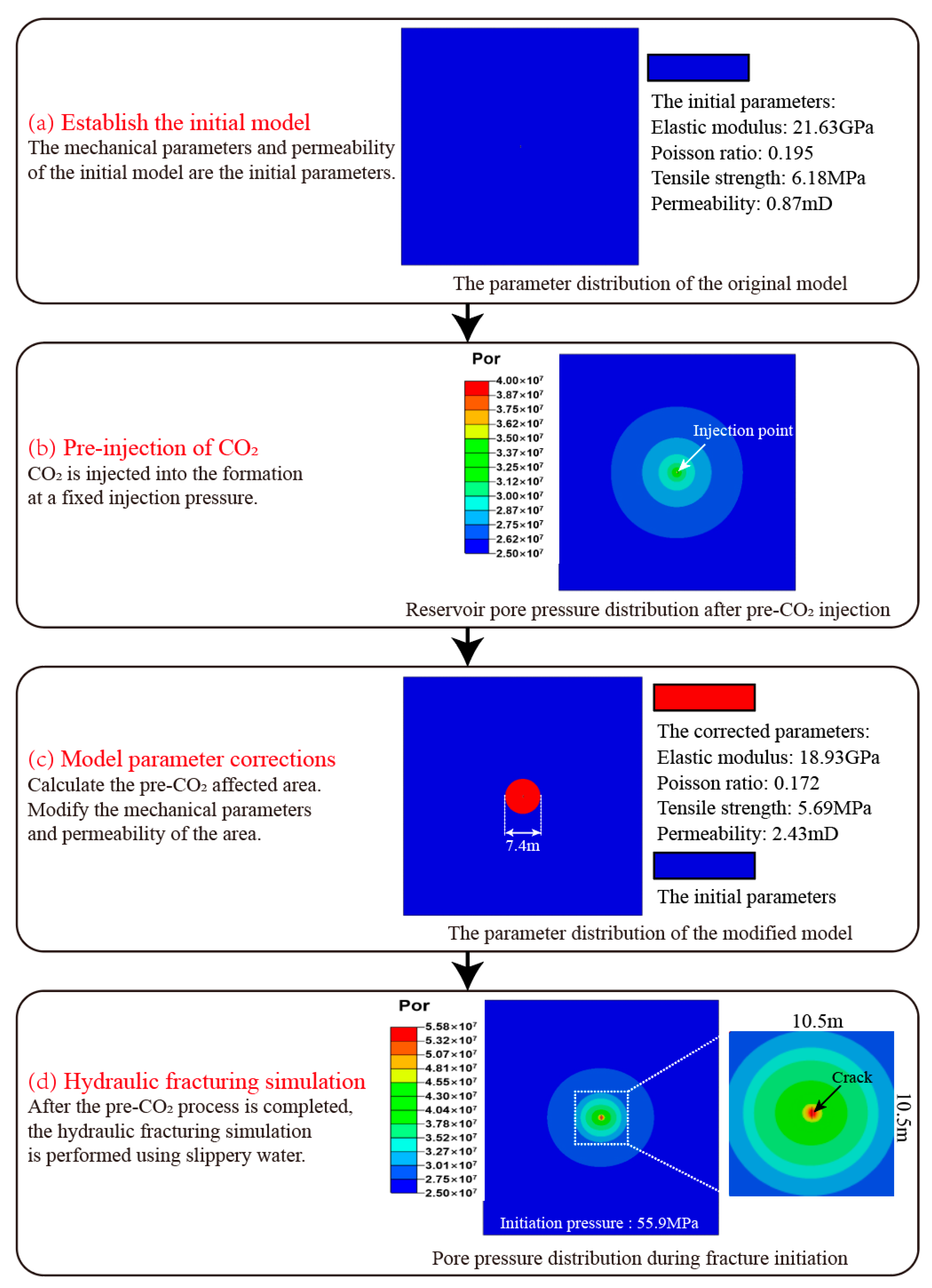
After being treated with carbon dioxide in situ, the elastic modulus of reservoir shale decreased by 12.5%, Poisson’s ratio decreased by 11.8%, the tensile strength decreased by 7.9%, and the permeability increased by 180%.
(2)
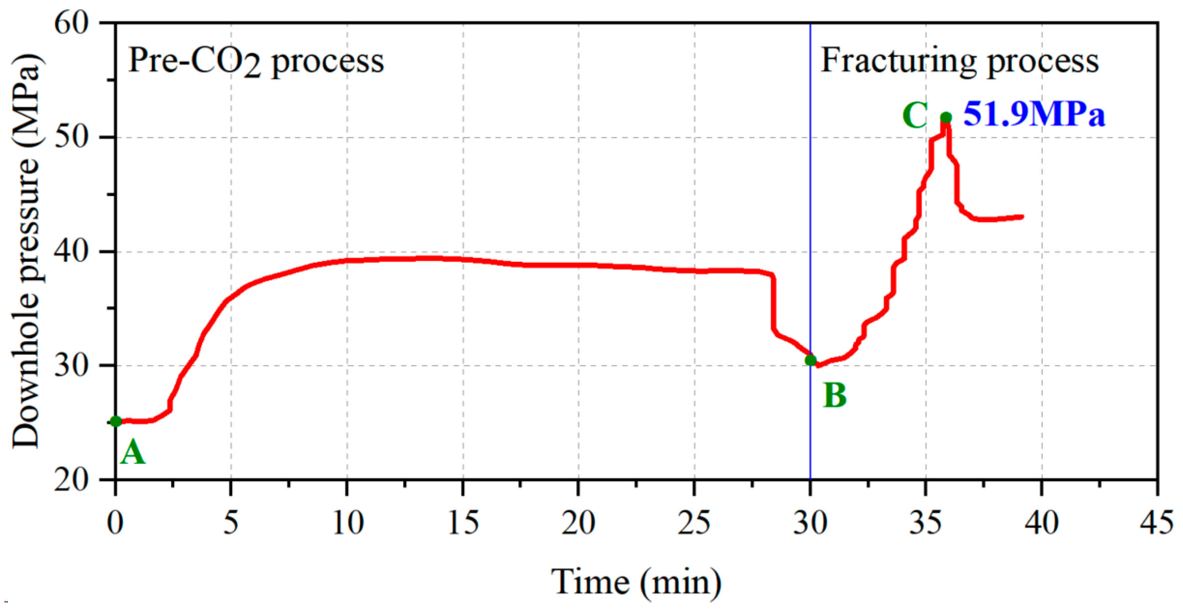
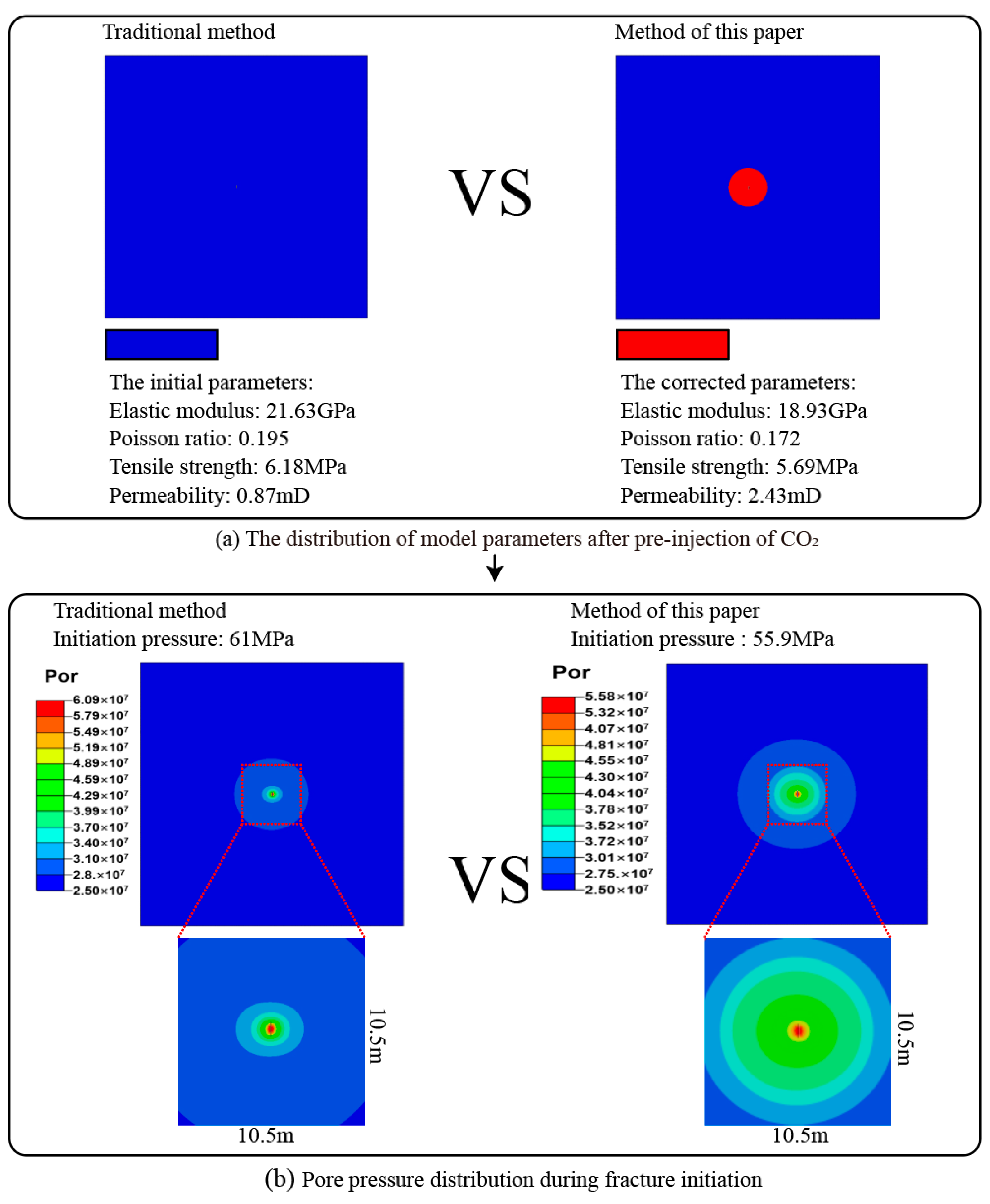
Upon pre-CO2 injection into the reservoir, there was a noteworthy increase in pore pressure within the near-wellbore region. This augmentation not only supplemented formation capacity but also induced modifications in the reservoir rocks near the wellbore area.
(3)
The accurate prediction of pre-CO2 fracturing initiation pressure necessitates the consideration of CO2’s influence on the modification of reservoir rock mechanical properties. In comparison with traditional numerical simulation methods, the approach proposed in this paper achieves a reduction in the predicted initiation pressure error of 9.8%.
(4)
This study provides guidance for the design of operational parameters in pre-injected CO2 fracturing.

Author Contributions

Conceptualization, C.K.; methodology, Z.C. and A.S.; investigation, Y.S.; writing—original draft preparation, A.S. and Z.C.; writing—review and editing, J.W., G.L., Y.Y., C.T. and X.W.; software, H.B. All authors have read and agreed to the published version of the manuscript.

Funding

The research was supported by the Heilongjiang “Open Competition” project (DQYT-2022-JS-758), the Shenyang Science and Technology Talent Project of China (No. RC230286), and the program of China Scholarships Council (No. 202306800021).

Data Availability Statement

The original contributions presented in this study are included in the article. Further inquiries can be directed to the corresponding authors.

Acknowledgments

The research was supported by the Heilongjiang “Open Competition” project (DQYT-2022-JS-758), the Shenyang Science and Technology Talent Project of China (No. RC230286), and the program of China Scholarships Council (No. 202306800021).

Conflicts of Interest

Authors Cuilong Kong, Hao Bian, Guo Li, Chao Tang, Xu Wei were employed by the company Daqing Oilfield Limited Company. The remaining authors declare that the research was conducted in the absence of any commercial or financial relationships that could be construed as a potential conflict of interest. The Daqing Oilfield Limited Company had no role in the design of the study; in the collection, analyses, or interpretation of data; in the writing of the manuscript, or in the decision to publish the results.

References

  1. Sun, X.; Yao, D.; Qu, J.; Sun, S.; Qin, Z.; Tao, L.; Zhao, Y. A novel transient hole cleaning algorithm for horizontal wells based on drift-flux model. Geoenergy Sci. Eng. 2024, 233, 212517. [Google Scholar] [CrossRef]
  2. Cong, Z.; Li, Y.; Tang, J.; Martyushev, D.A.; Yang, F. Numerical simulation of hydraulic fracture height layer-through propagation based on three-dimensional lattice method. Eng. Fract. Mech. 2022, 264, 108331. [Google Scholar] [CrossRef]
  3. Li, Y.; Long, M.; Tang, J.; Chen, M.; Fu, X. A hydraulic fracture height mathematical model considering the influence of plastic region at fracture tip. Pet. Explor. Dev. 2020, 47, 175–185. [Google Scholar] [CrossRef]
  4. Zhang, X.; Zhu, W.; Xu, Z.; Liu, S.; Wei, C. A review of experimental apparatus for supercritical CO2 fracturing of shale. J. Pet. Sci. Eng. 2022, 208, 109515. [Google Scholar] [CrossRef]
  5. Li, Y.; Peng, G.; Tang, J.; Zhang, J.; Zhao, W.; Liu, B.; Pan, Y. Thermo-hydro-mechanical coupling simulation for fracture propagation in CO2 fracturing based on phase-field model. Energy 2023, 284, 128629. [Google Scholar] [CrossRef]
  6. Cong, Z.; Li, Y.; Pan, Y.; Liu, B.; Shi, Y.; Wei, J.; Li, W. Study on CO2 foam fracturing model and fracture propagation simulation. Energy 2022, 238, 121778. [Google Scholar] [CrossRef]
  7. Zhao, H.; Wu, K.; Huang, Z.; Xu, Z.; Shi, H.; Wang, H. Numerical model of CO2 fracturing in naturally fractured reservoirs. Eng. Fract. Mech. 2021, 244, 107548. [Google Scholar] [CrossRef]
  8. Liu, B.; Suzuki, A.; Ito, T. Estimating the seepage effect of SC-CO2 and water fracturing with a steady-state flow model considering capillary and viscous forces at the pore scale. J. Pet. Sci. Eng. 2020, 184, 106483. [Google Scholar] [CrossRef]
  9. Sun, H.; Chen, J.; Ji, X.; Karunakaran, G.; Chen, B.; Ranjith, P.G.; Song, Y.; Yang, M. Optimizing CO2 hydrate storage: Dynamics and stability of hydrate caps in submarine sediments. Appl. Energy 2024, 376, 124309. [Google Scholar] [CrossRef]
  10. Li, Y.; Li, J.; Peng, J.; Ge, D.; Bo, K. Effect of artificially induced microcracks near the rock surface on granite fragmentation performance under heating treatment. Int. J. Rock Mech. Min. Sci. 2024, 182, 105894. [Google Scholar] [CrossRef]
  11. Yarushina, V.M.; Bercovici, D.; Oristaglio, M.L. Rock deformation models and fluid leak-off in hydraulic fracturing. Geophys. J. Int. 2013, 194, 1514–1526. [Google Scholar] [CrossRef]
  12. Wang, J.; Wang, Z.; Sun, B.; Gao, Y.; Wang, X.; Fu, W. Optimization design of hydraulic parameters for supercritical CO2 fracturing in unconventional gas reservoir. Fuel 2019, 235, 795–809. [Google Scholar] [CrossRef]
  13. Zhou, J.; Liu, G.; Jiang, Y.; Xian, X.; Liu, Q.; Zhang, D.; Tan, J. Supercritical carbon dioxide fracturing in shale and the coupled effects on the permeability of fractured shale: An experimental study. J. Nat. Gas Sci. Eng. 2016, 36, 369–377. [Google Scholar] [CrossRef]
  14. Li, Y.; Long, M.; Zuo, L.; Li, W.; Zhao, W. Brittleness evaluation of coal based on statistical damage and energy evolution theory. J. Pet. Sci. Eng. 2019, 172, 753–763. [Google Scholar] [CrossRef]
  15. Hou, L.; Zhang, S.; Elsworth, D.; Liu, H.; Sun, B.; Geng, X. Review of fundamental studies of CO2 fracturing: Fracture propagation, propping and permeating. J. Pet. Sci. Eng. 2021, 205, 108823. [Google Scholar] [CrossRef]
  16. Liu, B.; Suzuki, A.; Ito, T. Numerical analysis of different fracturing mechanisms between supercritical CO2 and water-based fracturing fluids. Int. J. Rock Mech. Min. Sci. 2020, 132, 104385. [Google Scholar] [CrossRef]
  17. Middleton, R.; Viswanathan, H.; Currier, R.; Gupta, R. CO2 as a fracturing fluid: Potential for commercial-scale shale gas production and CO2 sequestration. Energy Procedia 2014, 63, 7780–7784. [Google Scholar] [CrossRef]
  18. Zou, Y.; Li, S.; Ma, X.; Zhang, S.; Li, N.; Chen, M. Effects of CO2–brine–rock interaction on porosity/permeability and mechanical properties during supercritical-CO2 fracturing in shale reservoirs. J. Nat. Gas Sci. Eng. 2018, 49, 157–168. [Google Scholar] [CrossRef]
  19. Ishida, T.; Chen, Y.; Bennour, Z.; Yamashita, H.; Inui, S.; Nagaya, Y.; Naoi, M.; Chen, Q.; Nakayama, Y.; Nagano, Y. Features of CO2 fracturing deduced from acoustic emission and microscopy in laboratory experiments. J. Geophys. Res. Solid Earth 2016, 121, 8080–8098. [Google Scholar] [CrossRef]
  20. Ishida, T.; Aoyagi, K.; Niwa, T.; Chen, Y.; Murata, S.; Chen, Q.; Nakayama, Y. Acoustic emission monitoring of hydraulic fracturing laboratory experiment with supercritical and liquid CO2. Geophys. Res. Lett. 2012, 39, L16309. [Google Scholar] [CrossRef]
  21. Kizaki, A.; Tanaka, H.; Ohashi, K.; Sakaguchi, K.; Matsuki, K. Hydraulic fracturing in Inada granite and Ogino tuff with super critical carbon dioxide. In Proceedings of the ISRM International Symposium-Asian Rock Mechanics Symposium, ISRM 2012, Seoul, Republic of Korea, 15–19 October 2012; p. ISRM-ARMS7-2012-109. [Google Scholar]
  22. Zhang, X.; Lu, Y.; Tang, J.; Zhou, Z.; Liao, Y. Experimental study on fracture initiation and propagation in shale using supercritical carbon dioxide fracturing. Fuel 2017, 190, 370–378. [Google Scholar] [CrossRef]
  23. Bennour, Z.; Ishida, T.; Nagaya, Y.; Chen, Y.; Nara, Y.; Chen, Q.; Sekine, K.; Nagano, Y. Crack extension in hydraulic fracturing of shale cores using viscous oil, water, and liquid carbon dioxide. Rock Mech. Rock Eng. 2015, 48, 1463–1473. [Google Scholar] [CrossRef]
  24. Zou, Y.; Li, N.; Ma, X.; Zhang, S.; Li, S. Experimental study on the growth behavior of supercritical CO2-induced fractures in a layered tight sandstone formation. J. Nat. Gas Sci. Eng. 2018, 49, 145–156. [Google Scholar] [CrossRef]
  25. Yan, H.; Zhang, J.; Zhou, N.; Li, M. Staged numerical simulations of supercritical CO2 fracturing of coal seams based on the extended finite element method. J. Nat. Gas Sci. Eng. 2019, 65, 275–283. [Google Scholar] [CrossRef]
  26. He, Y.; Yang, Z.; Jiang, Y.; Li, X.; Zhang, Y.; Song, R. A full three-dimensional fracture propagation model for supercritical carbon dioxide fracturing. Energy Sci. Eng. 2020, 8, 2894–2906. [Google Scholar] [CrossRef]
  27. Zhang, C.; Cheng, P.; Ranjith, P.; Lu, Y.; Zhou, J. A comparative study of fracture surface roughness and flow characteristics between CO2 and water fracturing. J. Nat. Gas Sci. Eng. 2020, 76, 103188. [Google Scholar] [CrossRef]
  28. Middleton, R.S.; Carey, J.W.; Currier, R.P.; Hyman, J.D.; Kang, Q.; Karra, S.; Jiménez-Martínez, J.; Porter, M.L.; Viswanathan, H.S. Shale gas and non-aqueous fracturing fluids: Opportunities and challenges for supercritical CO2. Appl. Energy 2015, 147, 500–509. [Google Scholar] [CrossRef]
  29. Zhang, J.; Li, Y.; Pan, Y.; Wang, X.; Yan, M.; Shi, X.; Zhou, X.; Li, H. Experiments and analysis on the influence of multiple closed cemented natural fractures on hydraulic fracture propagation in a tight sandstone reservoir. Eng. Geol. 2021, 281, 105981. [Google Scholar] [CrossRef]
  30. Cong, Z.; Li, Y.; Liu, Y.; Xiao, Y. A new method for calculating the direction of fracture propagation by stress numerical search based on the displacement discontinuity method. Comput. Geotech. 2021, 140, 104482. [Google Scholar] [CrossRef]
  31. Li, Y.; Dai, H.; Zhang, J.; Ma, X.; Yu, Y.; Cong, Z.; Xiao, Y. Numerical simulation of proppant migration in horizontal wells with multi-fracture fracturing. Geoenergy Sci. Eng. 2023, 227, 211964. [Google Scholar] [CrossRef]
  32. Wang, L.; Yao, B.; Xie, H.; Winterfeld, P.H.; Kneafsey, T.J.; Yin, X.; Wu, Y.-S. CO2 injection-induced fracturing in naturally fractured shale rocks. Energy 2017, 139, 1094–1110. [Google Scholar] [CrossRef]
  33. He, L.; Feng, W.; Zhang, J.; Siwei, M.; Yongwei, D. Fracturing with carbon dioxide: Application status and development trend. Pet. Explor. Dev. 2014, 41, 513–519. [Google Scholar]
  34. Deng, B.; Yin, G.; Li, M.; Zhang, D.; Lu, J.; Liu, Y.; Chen, J. Feature of fractures induced by hydrofracturing treatment using water and L-CO2 as fracturing fluids in laboratory experiments. Fuel 2018, 226, 35–46. [Google Scholar] [CrossRef]
  35. Zhang, J.; Xingyao, Y.; Zhang, G.; Yipeng, G.; Xianggang, F. Prediction method of physical parameters based on linearized rock physics inversion. Pet. Explor. Dev. 2020, 47, 59–67. [Google Scholar] [CrossRef]
  36. Haque, M.S.; Stewart, C.M. Comparative analysis of the sin-hyperbolic and Kachanov–Rabotnov creep-damage models. Int. J. Press. Vessel. Pip. 2019, 171, 1–9. [Google Scholar] [CrossRef]
  37. Li, Y.; Peng, J.; Huang, C.; Lian, M.; Xu, T.; Zhang, Y.; Bo, K.; Feng, B.; Zhou, J. Multi-fractured stimulation technique of hydraulic fracturing assisted by the DTH-hammer-induced impact fractures. Geothermics 2019, 82, 63–72. [Google Scholar] [CrossRef]
  38. Gaus, I. Role and impact of CO2–rock interactions during CO2 storage in sedimentary rocks. Int. J. Greenh. Gas Control 2010, 4, 73–89. [Google Scholar] [CrossRef]
  39. Whitaker, S. Flow in porous media I: A theoretical derivation of Darcy’s law. Transp. Porous Media 1986, 1, 3–25. [Google Scholar] [CrossRef]
Figure 1. Experimental samples.
Processes 12 02525 g001
Figure 2. Experimental flowchart.
Processes 12 02525 g002
Figure 3. Triaxial compression experimental results.
Processes 12 02525 g003
Figure 4. Experimental results of tensile strength test.
Processes 12 02525 g004
Figure 5. Comparison of rocks’ elastic modulus before and after CO2 treatment.
Processes 12 02525 g005
Figure 6. Comparison of rocks’ Poisson’s ratio before and after CO2 treatment.
Processes 12 02525 g006
Figure 7. Comparison of rock tensile strength before and after CO2 treatment.
Processes 12 02525 g007
Figure 8. Comparison of rock permeability before and after CO2 treatment.
Processes 12 02525 g008
Figure 9. Actual fracturing curve.
Processes 12 02525 g009
Figure 10. Numerical simulation results of pre-CO2 fracturing.
Processes 12 02525 g010
Figure 11. Calculation results of traditional methods for simulating pre-CO2 fracturing.
Processes 12 02525 g011
Table 1. Experimental results.
Saturated Oil ShaleCO2-Modified Shale
Elastic modulus (Gpa)21.6318.93
Poisson’s ratio0.1950.172
Tensile strength (Mpa)6.185.69
Permeability (mD)0.872.43
Table 2. Numerical simulation parameters.
ParametersValueUnit
Model size50∗50m
Reservoir temperature110°C
Vertical in situ stress50MPa
Minimum horizontal principal stress45MPa
Maximum horizontal principal stress55MPa
Porosity4.3%/
Formation pressure25MPa
Fracturing section length50M
Pre-CO2 injection pressure40MPa
Pre-CO2 injection time30min
Pre-CO2 injection volume75m3
Bound water saturation0.18/
Initial elastic modulus21.63GPa
Elastic modulus after CO2 action18.93GPa
Initial Poisson’s ratio0.195/
Poisson’s ratio after CO2 action0.172/
Initial tensile strength6.18MPa
Tensile strength after CO2 action5.69MPa
Initial permeability0.87mD
Permeability after CO2 action2.43mD
Smooth water fracturing flow rate16m3/min
CO2 viscosity0.0001Pa·s
Slippery water viscosity0.001Pa·s
Disclaimer/Publisher’s Note: The statements, opinions and data contained in all publications are solely those of the individual author(s) and contributor(s) and not of MDPI and/or the editor(s). MDPI and/or the editor(s) disclaim responsibility for any injury to people or property resulting from any ideas, methods, instructions or products referred to in the content.

