
CFD Simulation of Stirling Engines: A Review


Abstract
1. Introduction
2. Computational Analysis Methods of Stirling Engines
2.1. Main Features of Computational Fluid Dynamics
2.2. Specific Aspects of CFD Applied to Stirling Engines
- Three-dimensionality;
- Transience;
- Compressibility;
- Working fluid described as a real gas;
- Turbulent flow dynamics;
- Conjugate heat transfer, likely including radiation if operating at a high temperature;
- Porous media flow in the regenerator;
- Dynamic hybrid meshes need to be used;
- High-order numerical discretization schemes, spatial and temporal, are needed.
3. CFD Simulations of Stirling Engines
3.1. Simulation of Non-Kinetic Stirling Engines
3.2. CFD Simulations of the Regenerator Considering Its Microstructure
3.3. Stirling CFD Studies Including Radiation Model
3.4. CFD Simulations of Stirling Cryocooler
4. Guidelines for Reporting CFD Simulation Studies of Stirling Engines
- The computational domain must be properly defined, specifying clearly its geometry and dimensions. The deformable subdomains must be clearly identified from those that keep a fixed shape and volume. At this point, the porous zones (i.e., regenerators) must also be distinguished;
- Meshing. The type of mesh employed (structured, unstructured, hybrid) and the algorithm employed for describing the grid deformation in dynamic meshes must be stated. Moreover, the characteristics of the near-wall mesh need to be given, especially in turbulent flows, where the number of layers employed to resolve the boundary layer behavior must be specified;
- Physical models. The governing laws in each subdomain must be stated, illustrating the variables to be solved. Also, the simplifications of such laws, if any, must be highlighted. For instance, the fluid governing equations expressing mass, momentum, and energy conservation, generally valid, can be simplified in cases of incompressible, Newtonian, constant-property fluids and solved in two- or three-dimensional configurations in a steady or transient state. In Stirling engines, the regenerator is typically considered as a porous zone and the corresponding ruling expressions should also be reported, as well as the relevant parameters (e.g., porosity, friction factors…) In the case of turbulent flows, the model of turbulence has to be clearly identified;
- Boundary conditions must be clearly highlighted in a figure and fully specified. If geometrical symmetry is employed to reduce the computational domain (and computational effort) it should be emphasized, and the corresponding symmetry or periodic boundary conditions must be properly identified;
- If certain internal or external surfaces or volumes are subject to some motion and/or deformation, either prescribed or as a result of the interaction with the working fluid, they must be pinpointed. Also, such a motion must be unambiguously documented;
- Initial conditions have to be provided for all variables in every subdomain;
- Physical properties of the employed materials (solid walls, working fluids, regenerator solid matrix) must be reported (e.g., density, viscosity, ideal or real gas considered);
- Numerical schemes. The type and order of the discretization schemes for both space and time have to be stated for each considered variable, possibly in a table. In the case of transient simulation, the time step should be clearly identified;
- Verification: Spatial and temporal discretization independence studies must be reported using at least three levels, to ensure that the results have become independent of the mesh density and time step employed;
- Sensitivity study of results versus employed turbulence model. Report of the maximum and average values of the variable and Courant number;
- Comprehensive report of results attending not only to integral parameters, such as power output or heat transfer efficiency, but also to local and instantaneous fields. Contour plots are suggested to illustrate the behavior of the main variables such as velocity, pressure, and temperature. In the case of turbulent flow corresponding variables such as turbulent kinetic energy, the turbulent viscosity ratio, and dissipation also have to be illustrated;
- Finally, a validation of the computational results must be provided versus reference experiments or a comparison with previous simulations, if experiments are not available. Ideally, such a validation should be carried out not only with integral parameters but also with some local or instantaneous variables. However, this requirement is acknowledged to be quite difficult in Stirling engines, given the nature of the experiments.
5. Conclusions and Perspectives
Author Contributions
Funding
Data Availability Statement
Acknowledgments
Conflicts of Interest
References
- Moonka, G.; Surana, H.; Singh, H.R. Study on some aspects of Stirling engine: A path to solar Stirling engines. Mater. Today Proc. 2022, 63, 737–744. [Google Scholar] [CrossRef]
- Yang, C. Promising Stirling Engine: Advancement and Applications. Highlights Sci. Eng. Technol. 2024, 88, 827–834. [Google Scholar] [CrossRef]
- Kubule, A.; Kramens, J.; Bimbere, M.; Pedišius, N.; Blumberga, D. Trends for Stirling Engines in Households: A Systematic Literature Review. Energies 2024, 17, 383. [Google Scholar] [CrossRef]
- Bianchi, M.; De Pascale, A. Bottoming cycles for electric energy generation: Parametric investigation of available and innovative solutions for the exploitation of low and medium temperature heat sources. Appl. Energy 2011, 88, 1500–1509. [Google Scholar] [CrossRef]
- Perozziello, C.; Grosu, L.; Vaglieco, B.M. Free-Piston Stirling Engine Technologies and Models: A Review. Energies 2021, 14, 7009. [Google Scholar] [CrossRef]
- Der Minassians, A. Stirling Engines for Low-Temperature Solar-Thermal-Electric Power Generation. Ph.D. Thesis, University of Berkeley, Berkeley, CA, USA, 2007. [Google Scholar]
- Féniès, G.; Formosa, F.; Ramousse, J.; Badel, A. Double acting Stirling engine: Modelling, experiments and optimization. Appl. Energy 2015, 159, 350–361. [Google Scholar] [CrossRef]
- Thombare, D.G.; Verma, S.K. Technological development in the Stirling cycle engines. Renew. Sustain. Energy Rev. 2008, 12, 1–38. [Google Scholar] [CrossRef]
- Vineeth, C.S. Stirling Engines: A Beginners Guide, 2nd ed.; 2011; Available online: https://www.google.com.co/books/edition/Stirling_Engines/zTdzKxQaqNcC?hl=es-419&gbpv=0 (accessed on 26 May 2024).
- Wang, K.; Sanders, S.R.; Dubey, S.; Choo, F.H.; Duan, F. Stirling cycle engines for recovering low and moderate temperature heat: A review. Renew. Sustain. Energy Rev. 2016, 62, 89–108. [Google Scholar] [CrossRef]
- Zeiler, M.; Padinger, R.; Spitzer, J.; Podesser, E. Operating experiences with biomass driven Stirling engines; 3 kW and 30 kW. In Proceedings of the 13th International Stirling Conference, Tokyo, Japan, 23–26 September 2007. [Google Scholar]
- Bataineh, K. Mathematical formulation of alpha-type Stirling engine with Ross Yoke mechanism. Energy 2018, 164, 1178–1199. [Google Scholar] [CrossRef]
- Vinoth Kumar, D. Modification of an alpha stirling engine with an venturi based working fluid control system to promote its automotive applications. Int. J. Mech. Eng. Robot. Res. 2014, 3, 101–113. [Google Scholar]
- Ahmadi, M.H.; Ahmadi, M.A.; Pourfayaz, F. Thermal models for analysis of performance of Stirling engine: A review. Renew. Sustain. Energy Rev. 2017, 68, 168–184. [Google Scholar] [CrossRef]
- Timoumi, Y.; Tlili, I.; Ben Nasrallah, S. Design and performance optimization of GPU-3 Stirling engines. Energy 2008, 33, 1100–1114. [Google Scholar] [CrossRef]
- Singh, U.R.; Kumar, A. Review on solar Stirling engine: Development and performance. Therm. Sci. Eng. Prog. 2018, 8, 244–256. [Google Scholar] [CrossRef]
- Schneider, T.; Müller, D.; Karl, J. A review of thermochemical biomass conversion combined with Stirling engines for the small-scale cogeneration of heat and power. Renew. Sustain. Energy Rev. 2020, 134, 110288. [Google Scholar] [CrossRef]
- Getie, M.Z.; Lanzetta, F.; Bégot, S.; Admassu, B.T.; Hassen, A.A. Reversed regenerative Stirling cycle machine for refrigeration application: A review. Int. J. Refrig. 2020, 118, 173–187. [Google Scholar] [CrossRef]
- Zare, S.; Tavakolpour-saleh, A.R.; Aghahosseini, A.; Sangdani, M.H.; Mirshekari, R. Design and optimization of Stirling engines using soft computing methods: A review. Appl. Energy 2021, 283, 116258. [Google Scholar] [CrossRef]
- Zayed, M.E.; Zhao, J.; Elsheikh, A.H.; Li, W.; Sadek, S.; Aboelmaaref, M.M. A comprehensive review on Dish/Stirling concentrated solar power systems: Design, optical and geometrical analyses, thermal performance assessment, and applications. J. Clean. Prod. 2021, 283, 124664. [Google Scholar] [CrossRef]
- Malik, M.Z.; Shaikh, P.H.; Zhang, S.; Lashari, A.A.; Leghari, Z.H.; Baloch, M.H.; Memon, Z.A.; Caiming, C. A review on design parameters and specifications of parabolic solar dish Stirling systems and their applications. Energy Rep. 2022, 8, 4128–4154. [Google Scholar] [CrossRef]
- Boretti, A. α–Stirling hydrogen engines for concentrated solar power. Int. J. Hydrogen Energy 2021, 46, 16241–16247. [Google Scholar] [CrossRef]
- Zhu, S.; Yu, G.; Liang, K.; Dai, W.; Luo, E. A review of Stirling-engine-based combined heat and power technology. Appl. Energy 2021, 294, 116965. [Google Scholar] [CrossRef]
- Zhang, L.; Han, K.; Wang, Y.; Zhu, Y.; Zhong, S.; Zhong, G. A bibliometric analysis of Stirling engine and in-depth review of its application for energy supply systems. Energy Rev. 2023, 2, 100048. [Google Scholar] [CrossRef]
- Martini, R. Stirling Engine Design Manual, 2nd ed.; NASA Report CR-168088; NASA: Washington, DC, USA, 1983.
- Chen, N.C.J.; Griffin, F.P. A Review of Stirling Engine Mathematical Models; Oak Ridge National Laboratory ORNL/CON-135; Oak Ridge National Lab. (ORNL): Oak Ridge, TN, USA, 1983. [Google Scholar]
- West, C.D. Principles and Applications of Stirling Engines, 1st ed.; Van Nostrand Reinhold: New York, NY, USA, 1986. [Google Scholar]
- Urieli, I.; Berchowitz, D.M. Stirling Cycle Engine Analysis, 1st ed.; Taylor and Francis: London, UK, 1984. [Google Scholar]
- Urieli, I. A Computer Simulation of Stirling Cycle Machines. Ph.D. Thesis, University of Johannesburg, Johannesburg, South Africa, 1977. [Google Scholar]
- Finkelstein, T. Generalized Thermodynamic Analysis of Stirling Engines; SAE Technical Paper 600222; SAE: Warrendale, PA, USA, 1960. [Google Scholar] [CrossRef]
- Dyson, R.W.; Wilson, S.D.; Tew, R.C. Review of Computational Stirling Analysis Methods; NASA/TM—2004-213300 Report; NASA: Washington, DC, USA, 2004.
- Alfarawi, S.; Al-Dadah, R.; Mahmoud, S. Influence of phase angle and dead volume on gamma-type Stirling engine power using CFD simulation. Energy Convers. Manag. 2016, 124, 130–140. [Google Scholar] [CrossRef]
- Chen, W.L.; Wong, K.L.; Chang, Y.F. A computational fluid dynamics study on the heat transfer characteristics of the working cycle of a low-temperature-differential γ-type Stirling engine. Int. J. Heat Mass Transf. 2014, 75, 145–155. [Google Scholar] [CrossRef]
- Kuban, L.; Stempka, J.; Tyliszczak, A. A 3D-CFD study of a γ-type Stirling engine. Energy 2019, 169, 142–159. [Google Scholar] [CrossRef]
- Mahkamov, K. Design Improvements to a Biomass Stirling Engine Using Mathematical Analysis and 3D CFD Modeling. J. Energy Resour. Technol. 2006, 128, 203–215. [Google Scholar] [CrossRef]
- Versteeg, H.; Malalasekera, W. An Introduction to Computational Fluid Dynamics: The Finite Volume Method, 2nd ed.; Pearson: Essex, UK, 2007. [Google Scholar]
- López, O.D.; Quiñones, J.J.; Lain, S. RANS and Hybrid RANS-LES simulations of an H-type Darrieus vertical axis water turbine. Energies 2018, 11, 2348. [Google Scholar] [CrossRef]
- Lain, S.; García, M.; Quintero, B.; Orrego, S. CFD numerical simulations of Francis turbines. Rev. Fac. Ing. Univ. Antioq. 2010, 51, 24–33. [Google Scholar] [CrossRef]
- O’Brien, J.M.; Young, T.M.; Early, J.M.; Griffin, P.C. An assessment of commercial CFD turbulence models for near wake HAWT modelling. J. Wind. Eng. Ind. Aerodyn. 2018, 176, 32–53. [Google Scholar] [CrossRef]
- Sanaye, S.; Farvizi, A. Optimizing a vertical axis wind turbine with helical blades: Application of 3D CFD and Taguchi method. Energy Rep. 2024, 12, 2527–2547. [Google Scholar] [CrossRef]
- Lain, S.; Taborda, M.A.; López, O.D. Numerical study of the effect of winglets on the performance of a straight blade Darrieus water turbine. Energies 2018, 11, 297. [Google Scholar] [CrossRef]
- Nassini, P.C.; Pampaloni, D.; Meloni, R.; Andreini, A. Lean blow-out prediction in an industrial gas turbine combustor through a LES-based CFD analysis. Combust. Flame 2021, 229, 111391. [Google Scholar] [CrossRef]
- Baratta, M.; Chiriches, S.; Goel, P.; Misul, D. CFD modelling of natural gas combustion in IC engines under different EGR dilution and H2-doping conditions. Transp. Eng. 2020, 2, 100018. [Google Scholar] [CrossRef]
- Chaturvedi, S.; Santhosh, R.; Mashruk, S.; Yadav, R.; Valera-Medina, A. Prediction of NOx emissions and pathways in premixed ammonia-hydrogen-air combustion using CFD-CRN methodology. J. Energy Inst. 2023, 111, 101406. [Google Scholar] [CrossRef]
- Li, Z.; Tang, D.; Du, J.; Li, T. Study of the radiation flux and temperature distributions of the concentrator-receiver system in a solar dish/Stirling power facility. Appl. Therm. Eng. 2011, 31, 1780–1789. [Google Scholar] [CrossRef]
- Khoshvaght-Aliabadi, M.; Ghodrati, P.; Mahian, O.; Kang, Y.T. CFD study of rib-enhanced printed circuit heat exchangers for precoolers in solar power plants’ supercritical CO2 cycle. Energy 2024, 292, 130418. [Google Scholar] [CrossRef]
- Tarodiya, R.; Khullar, S.; Levy, A. Particulate flow and erosion modeling of a Pelton turbine injector using CFD-DEM simulations. Powder Technol. 2022, 399, 117168. [Google Scholar] [CrossRef]
- Ahmed, S.; Hassan, A.; Zubair, R.; Rashid, S.; Ullah, A. Design modification in an industrial multistage orifice to avoid cavitation using CFD simulation. J. Taiwan Inst. Chem. Eng. 2023, 148, 104833. [Google Scholar] [CrossRef]
- López, O.D.; Mejía, O.E.; Escorcia, K.M.; Suárez, F.; Lain, S. Comparison of sliding and overset mesh techniques in the simulation of a vertical axis turbine for hydrokinetic applications. Processes 2021, 9, 1933. [Google Scholar] [CrossRef]
- Krzemianowski, Z.; Kaniecki, M. Low-head high specific speed Kaplan turbine for small hydropower—Design, CFD loss analysis and basic, cavitation and runaway investigations: A case study. Energy Convers. Manag. 2023, 276, 116558. [Google Scholar] [CrossRef]
- Tushar Choudahry, S. Computational analysis of IR-SOFC: Thermodynamic, electrochemical process and flow configuration dependency. Int. J. Hydrogen Energy 2016, 41, 1259–1271. [Google Scholar] [CrossRef]
- Gadhewal, R.; Ananthula, V.V.; Patnaikuni, V.S. CFD simulation of hot spot in PEM fuel cell with diverging and converging flow channels. Mater. Today Proc. 2023, 72, 410–416. [Google Scholar] [CrossRef]
- Zhang, L.; Yu, X.; Lv, Q.; Cao, F.; Wang, X. Study of transient indoor temperature for a HVAC room using a modified CFD method. Energy Procedia 2019, 160, 420–427. [Google Scholar] [CrossRef]
- Lain, S.; Sommerfeld, M.; Quintero, B. Numerical simulation of secondary flow in pneumatic conveying of solid particles in a horizontal circular pipe. Braz. J. Chem. Eng. 2009, 26, 583–594. [Google Scholar] [CrossRef]
- Zhang, J.; Poon, K.H.; Kwok, H.H.L.; Hou, F.; Cheng, J.C.P. Predictive control of HVAC by multiple output GRU—CFD integration approach to manage multiple IAQ for commercial heritage building preservation. Build. Environ. 2023, 245, 110802. [Google Scholar] [CrossRef]
- Lain, S.; Sommerfeld, M. A study of the pneumatic conveying of non-spherical particles in a turbulent horizontal channel flow. Braz. J. Chem. Eng. 2007, 24, 535–546. [Google Scholar] [CrossRef]
- Islam, M.T.; Chen, Y.; Seong, D.; Verhougstraete, M.; Son, Y.J. Effects of recirculation and air change per hour on COVID-19 transmission in indoor settings: A CFD study with varying HVAC parameters. Heliyon 2024, 10, e35092. [Google Scholar] [CrossRef]
- Salazar, J.L.; Chen, W.L. A computational fluid dynamics study on the heat transfer characteristics of the working cycle of a β -type Stirling engine. Energy Convers. Manag. 2014, 88, 177–188. [Google Scholar] [CrossRef]
- Chen, W.L. A study on the effects of geometric parameters in a low-temperature differential gamma-type Stirling engine using CFD. Int. J. Heat Mass Transf. 2017, 107, 1002–1013. [Google Scholar] [CrossRef]
- Chen, W.L.; Yang, Y.C.; Salazar, J.L. CFD parametric study on the performance of a low-temperature-differential γ -type Stirling engine. Energy Convers. Manag. 2015, 106, 635–643. [Google Scholar] [CrossRef]
- Kato, Y.; Saitoh, S.; Ishimatsu, K.; Iwamoto, M. Effect of geometry and speed on the temperatures estimated by CFD for an isothermal model of a gamma configuration low temperature differential Stirling engine with Flat-shaped heat exchangers. Appl. Therm. Eng. 2017, 115, 111–122. [Google Scholar] [CrossRef]
- Mohammadi, M.A.; Jafarian, A. CFD simulation to investigate hydrodynamics of oscillating flow in a beta-type Stirling engine. Energy 2018, 153, 287–300. [Google Scholar] [CrossRef]
- Caughley, A.; Sellier, M.; Gschwendtner, M.; Tucker, A. CFD analysis of a diaphragm free-piston Stirling cryocooler. Cryogenics 2016, 79, 7–16. [Google Scholar] [CrossRef]
- Regalado-Rodríguez, N.; Militello, C. Comparative study of the effects of increasing heat transfer area within compression and expansion chambers in combination with modified pistons in Stirling engines. A simulation approach based on CFD and a numerical thermodynamic model. Energy Convers. Manag. 2022, 263, 115930. [Google Scholar] [CrossRef]
- Dai, Z.; Wang, C.; Zhang, D.; Tian, W.; Qiu, S.; Su, G.H. Design and heat transfer optimization of a 1 kW free-piston Stirling engine for space reactor power system. Nucl. Eng. Technol. 2021, 53, 2184–2194. [Google Scholar] [CrossRef]
- Papurello, D.; Bertino, D.; Santarelli, M. CFD Performance Analysis of a Dish-Stirling System for Microgeneration. Processes 2021, 9, 1142. [Google Scholar] [CrossRef]
- Almajri, A.K.; Mahmoud, S.; Al-Dadah, R. Modelling and parametric study of an efficient Alpha type Stirling engine performance based on 3D CFD analysis. Energy Convers. Manag. 2017, 145, 93–106. [Google Scholar] [CrossRef]
- Ahmed, H.; Almajri, A.K.; Mahmoud, S.; Al-Dadah, R.; Ahmad, A. CFD modelling and parametric study of small-scale Alpha type Stirling Cryocooler. Energy Procedia 2017, 142, 1668–1673. [Google Scholar] [CrossRef]
- Abuelyamen, A.; Ben-Mansour, R. Energy efficiency comparison of Stirling engine types (α, β, and γ) using detailed CFD modeling. Int. J. Therm. Sci. 2018, 132, 411–423. [Google Scholar] [CrossRef]
- Bulińsky, Z.; Szczygieł, I.; Krysinski, T.; Stanek, W.; Czarnowska, L.; Gładysz, P.; Kabaj, A. Finite time thermodynamic analysis of small alpha-type Stirling engine in non-ideal polytropic conditions for recovery of LNG cryogenic exergy. Energy 2017, 141, 2559–2571. [Google Scholar] [CrossRef]
- Bulińsky, Z.; Szczygieł, I.; Kabaj, A.; Krysinski, T.; Gładysz, P.; Czarnowska, L.; Stanek, W. Performance analysis of the small-scale α-type stirling engine using computational fluid dynamics tools. J. Energy Resour. Technol. 2018, 140, 032001. [Google Scholar] [CrossRef]
- Bulińsky, Z.; Kabaj, A.; Krysiński, T.; Szczygieł, I.; Stanek, W.; Rutczyk, B.; Czarnowska, L.; Gładysz, P. A Computational Fluid Dynamics analysis of the influence of the regenerator on the performance of the cold Stirling engine at different working conditions. Energy Convers. Manag. 2019, 195, 125–138. [Google Scholar] [CrossRef]
- Xiao, G.; Sultan, U.; Ni, M.; Peng, H.; Zhou, X.; Wang, S.; Luo, Z. Design optimization with computational fluid dynamic analysis of β-type Stirling engine. Appl. Therm. Eng. 2018, 113, 87–102. [Google Scholar] [CrossRef]
- Kumaravelu, T.; Saadon, S.; Abu Talib, A.R. Heat transfer enhancement of a Stirling engine by using fins attachment in an energy recovery system. Energy 2022, 239, 121881. [Google Scholar] [CrossRef]
- Aksoy, F.; Cinar, C. Thermodynamic analysis of a beta-type Stirling engine with rhombic drive mechanism. Energy Convers. Manag. 2013, 75, 319–324. [Google Scholar] [CrossRef]
- El-Ghafour, S.A.; El-Ghandour, M.; Mikhael, N.N. Three-dimensional computational fluid dynamics simulation of Stirling engine. Energy Convers. Manag. 2019, 180, 533–549. [Google Scholar] [CrossRef]
- Chi, C.; Mou, J.; Lin, M.; Hong, G. CFD simulation and investigation on the operating mechanism of a beta-type free piston Stirling engine. Appl. Therm. Eng. 2020, 166, 114751. [Google Scholar] [CrossRef]
- Cheng, C.H.; Chen, Y.F. Numerical simulation of thermal and flow fields inside a 1-kW beta-type Stirling engine. Appl. Therm. Eng. 2017, 121, 554–561. [Google Scholar] [CrossRef]
- Castro Caetano, B.; Figueiredo Lara, I.; Ungaretti Borges, M.; Sandoval, O.R.; Molina Valle, R. A novel methodology on beta-type Stirling engine simulation using CFD. Energy Convers. Manag. 2019, 184, 510–520. [Google Scholar] [CrossRef]
- Rogdakis, E.; Bitsikas, P.; Dogkas, G.; Antonakos, G. Three-dimensional CFD study of a β-type Stirling Engine. Therm. Sci. Eng. Prog. 2019, 11, 302–316. [Google Scholar] [CrossRef]
- Bitsikas, P.; Rogdakis, E.; Dogkas, G. CFD study of heat transfer in Stirling engine regenerator. Therm. Sci. Eng. Prog. 2020, 17, 100492. [Google Scholar] [CrossRef]
- Ben-Mansour, R.; Abuelyamen, A.; Mokheimer, E.M.A. CFD analysis of radiation impact on Stirling engine performance. Energy Convers. Manag. 2017, 152, 354–356. [Google Scholar] [CrossRef]
- Arslan, T.A.; Solmaz, H.; Ipci, D.; Aksoy, F. Investigation of the effect of compression ratio on performance of a beta type Stirling engine with rhombic mechanism by CFD analysis. Environ. Prog. Sustain. Energy 2023, 42, e14076. [Google Scholar] [CrossRef]
- Abuelyamen, A.; Ben-Mansour, R.; Abualhamayel, H.; Mokheimer, E.M.A. Parametric study on beta-type Stirling engine. Energy Convers. Manag. 2017, 145, 53–63. [Google Scholar] [CrossRef]
- Thieme, L. High-Power Baseline and Motoring Test Results for the GPU-3 Stirling Engine; DOE/NASA/51040-31, NASA TM-82646; NASA: Washington, DC, USA, 1981.
- Yu, G.Y.; Luo, E.C.; Dai, W.; Hu, J.Y. Study of nonlinear processes of a large experimental thermoacoustic-Stirling heat engine by using computational fluid dynamics. J. Appl. Phys. 2007, 102, 074901. [Google Scholar] [CrossRef]
- Xia, M.; Chen, X. Analysis of resonant frequency of moving magnet linear compressor of stirling cryocooler. Int. J. Refrig. 2010, 33, 739–744. [Google Scholar] [CrossRef]
- Chen, G.; Wang, Y.; Tang, L.; Wang, K.; Yu, Z. Large Eddy Simulation of thermally induced oscillatory flow in a thermoacustic engine. Appl. Energy 2020, 276, 115458. [Google Scholar] [CrossRef]
- Mahkamov, K. An Axisymmetric Computational Fluid Dynamics Approach to the Analysis of the Working Process of a Solar Stirling Engine. J. Sol. Energy Eng. 2006, 128, 45–53. [Google Scholar] [CrossRef]
- Qiu, S.; Gao, Y.; Rinker, G.; Yanaga, K. Development of an advanced free-piston Stirling engine for micro combined heating and power application. Appl. Energy 2019, 235, 987–1000. [Google Scholar] [CrossRef]
- Zhao, W.; Li, R.; Li, H.; Zhang, Y.; Qiu, S. Numerical analysis of fluid dynamics and thermodynamics in Stirling engine. Appl. Therm. Eng. 2021, 189, 116727. [Google Scholar] [CrossRef]
- Umair, M.; Shah, A.N.; Kamran, M.S.; Farhan, M.; Anwar, Z. The CFD methodology for simulating pumping loss from displacer and piston seals of free piston Stirling engine. Therm. Sci. 2022, 26, 13–23. [Google Scholar] [CrossRef]
- Kim, H.S.; Gwak, I.C.; Lee, S.H. Numerical analysis of heat transfer area effect on cooling performance in regenerator of free-piston Stirling cooler. Case Stud. Therm. Eng. 2022, 32, 101875. [Google Scholar] [CrossRef]
- Costa, S.C.; Barrutia, H.; Esnaola, J.A.; Tutar, M. Numerical study of the pressure drop phenomena in wound woven wire matrix of a Stirling regenerator. Energy Convers. Manag. 2013, 67, 57–65. [Google Scholar] [CrossRef]
- Costa, S.C.; Barrutia, H.; Esnaola, J.A.; Tutar, M. Numerical study of the heat transfer in wound woven wire matrix of a Stirling regenerator. Energy Convers. Manag. 2014, 79, 255–264. [Google Scholar] [CrossRef]
- Costa, S.C.; Tutar, M.; Barreno, I.; Esnaola, J.A.; Barrutia, H.; García, D.; Gonzalez, M.A.; Prieto, J.I. Experimental and numerical flow investigation of Stirling engine regenerator. Energy 2014, 72, 800–812. [Google Scholar] [CrossRef]
- Costa, S.C.; Barreno, I.; Tutar, M.; Esnaola, J.A.; Barrutia, H. The thermal non-equilibrium porous media modelling for CFD study of woven wire matrix of a Stirling regenerator. Energy Convers. Manag. 2015, 89, 473–483. [Google Scholar] [CrossRef]
- Barreno, I.; Costa, S.C.; Cordon, M.; Tutar, M.; Urrutibeascoa, I.; Gomez, X.; Castillo, G. Numerical correlation for the pressure drops in Stirling engine heat exchangers. Int. J. Therm. Sci. 2015, 97, 68–81. [Google Scholar] [CrossRef]
- York, B.T.; MacDonald, B.D. Influence of misalignment and spacing on the pressure drop through wire mesh Stirling engine regenerators. Energy Convers. Manag. 2021, 245, 114588. [Google Scholar] [CrossRef]
- Mancisidor, A.M.; Gil, E.; Garciandia, F.; San Sebastian, M.; Lizaso, O.; Escubi, M. Stirling engine regenerator based on lattice structures manufactured by selective laser melting. Procedia CIRP 2018, 74, 72–75. [Google Scholar] [CrossRef]
- Beni, H.M.; Mortazavi, H. Mathematical modeling of the solar regenerative heat exchanger under turbulent oscillating flow: Applications of renewable and sustainable energy and artificial heart. Results Eng. 2022, 13, 100321. [Google Scholar] [CrossRef]
- Zhao, Y.; Dang, H. CFD simulation of a miniature coaxial Stirling-type pulse tube cryocooler operating at 128 Hz. Cryogenics 2016, 73, 53–59. [Google Scholar] [CrossRef]
- Dang, H.; Zhao, Y. CFD modeling and experimental verification of a single-stage coaxial Stirling-type pulse tube cryocooler without either double-inlet or multi-bypass operating at 30–35 K using mixed stainless steel mesh regenerator matrices. Cryogenics 2016, 78, 40–50. [Google Scholar] [CrossRef]
- Zhao, Y.; Yu, G.; Tan, J.; Mao, X.; Li, J.; Zha, R.; Li, N.; Dang, H. CFD modeling and experimental verification of oscillating flow and heat transfer processes in the micro coaxial Stirling-type pulse tube cryocooler operating at 90–170 Hz. Cryogenics 2018, 90, 30–40. [Google Scholar] [CrossRef]
- Clearman, W.M.; Cha, J.S.; Ghiaasiaan, S.M.; Kirkconnell, C.S. Anisotropic steady-flow hydrodynamic parameters of microporous media applied to pulse tube and Stirling cryocooler regenerators. Cryogenics 2008, 48, 112–121. [Google Scholar] [CrossRef]
- Karabulut, H.; Yücesu, H.S.; Koca, A. Manufacturing and testing of a V-type Stirling engine. Turk. J. Eng. Environ. Sci. 2000, 24, 71–80. [Google Scholar]
- Sun, H.; Yu, G.; Zhao, D.; Dai, W.; Luo, E. Numerical and experimental investigations on coiled resonance tube of a duplex Stirling cryocooler. Appl. Therm. Eng. 2024, 238, 121930. [Google Scholar] [CrossRef]
- Phung, D.T.; Cheng, C.H. Investigating dynamic characteristics and thermal-lag phenomenon in a thermal-lag engine using a CFD-mechanism dynamics model. Appl. Therm. Eng. 2024, 236, 121926. [Google Scholar] [CrossRef]
- Papis-Fraczek, K.; Zoładek, M.; Filipowicz, M. The possibilities of upgrading an existing concentrating solar thermal system—Case study. Energy Rep. 2021, 7, 28–32. [Google Scholar] [CrossRef]
- Li, Z.; Haramura, Y.; Tang, D.; Guo, C. Analysis on the heat transfer characteristics of a micro-channel type porous-sheets Stirling regenerator. Int. J. Therm. Sci. 2015, 94, 37–49. [Google Scholar] [CrossRef]
- Li, Z.; Haramura, Y.; Kato, Y.; Tang, D. Analysis of a high-performance model Stirling engine with compact porous-sheets heat exchangers. Energy 2014, 64, 31–43. [Google Scholar] [CrossRef]
- García, D.; Suárez, M.J.; Blanco, E.; Prieto, J.I. Experimental correlations and CFD model of a non-tubular heater for a Stirling solar engine micro-cogeneration unit. Appl. Therm. Eng. 2019, 153, 715–725. [Google Scholar] [CrossRef]
- Andersson, B.; Andersson, R.; Håkanson, L.; Mortensen, M.; Sudiyo, R.; van Wachem, B. Best practice guidelines. In Computational Fluid Dynamics for Engineers, 1st ed.; Cambridge University Press: Cambridge, UK, 2012; pp. 174–180. [Google Scholar] [CrossRef]
- Roache, P.J. Verification and Validation in Computational Science and Engineering, 1st ed.; Hermosa Publishers: Albuquerque, NM, USA, 1998. [Google Scholar]
- Impagnatiello, M.; Bolla, M.; Keskinen, K.; Giannakopoulos, G.; Frouzakis, C.E.; Wright, Y.M.; Bolouchos, K. Systematic assessment of data-driven approaches for wall heat transfer modelling for LES in IC engines using DNS data. Int. J. Heat Mass Transf. 2022, 183, 122109. [Google Scholar] [CrossRef]

| Reference | Simulation Type | Simulated Components | Relevant Comments |
|---|---|---|---|
| Abuelyamen and Ben-Mansour (2018) [69] | 2D Laminar | Varying-volume hot and cold cylinders with connecting pipe | Use of radiation model. No details about dynamic mesh treatment. Low thermal efficiency. No comparison with experiments |
| Bulińsky et al. (2017) [70] | - | Compression and expansion cylinders, regenerators and pistons | Development of 2nd order model to compare with CFD |
| Bulińsky et al. (2018) [71] | 2D Turbulent (k-ω) | Coaxial expansion, compression cylinders, and annular regenerator connecting the cylinders | Use of radiation model. Layering technique for piston motion. Assessment of analyzed Stirling engine performance by COP, exergy efficiency, and irreversibility factor. No comparison with experiments |
| Bulińsky et al. (2019) [72] | 2D Turbulent (k-ε standard, realizable, RNG; k-ω standard, SST) | Cylinder, expansion and compression chambers, regenerator | Use of radiation model. Inclusion of regenerator increases engine specific work and efficiency rises 10% on average. No comparison with experiments |
| Almajri et al. (2017) [67]; Ahmed et al. (2017) [68] | 3D Laminar | Regenerator, pistons, cylinder, and heat exchanger | Combination of thermodynamic model with CFD. Regenerator as porous medium. Comparison with experiments of engine power. CFD as a tool to improve design parameters and operating conditions |
| Reference | Simulation Type | Simulated Components | Relevant Comments |
|---|---|---|---|
| Abuelyamen and Ben-Mansour (2018) [69] | 2D Laminar | Varying hot and cold volumes, displacer, piston | Use of radiation model. No details about dynamic mesh treatment. Low thermal efficiency. No comparison with experiments |
| Xiao et al. (2018) [73] | 2D Turbulent (k-ε standard) | Heater and cooling pipes, regenerator, expansion and compression spaces | Optimizing engine. Regenerator as porous media. Smoothing and remeshing for mesh motion description. Comparison with experiments (PV cycle). Stirling engine performance very sensible to heat exchanger parts |
| Salazar and Chen (2014) [58] | 2D Laminar | Expansion and compression chambers, displacer, piston, and solid walls of engine acting as regenerator | CFD heat transfer rates very different from 2nd order models. No comparison with experiments |
| Kumaravelu et al. (2022) [74] | 3D Turbulent (k-ε standard) | Displacer, piston, expansion and compression volumes | Employing rectangular fins improves heat transfer rate, efficiency, and power output of engine. Comparison with experiments of power output vs. rotational speed [75] |
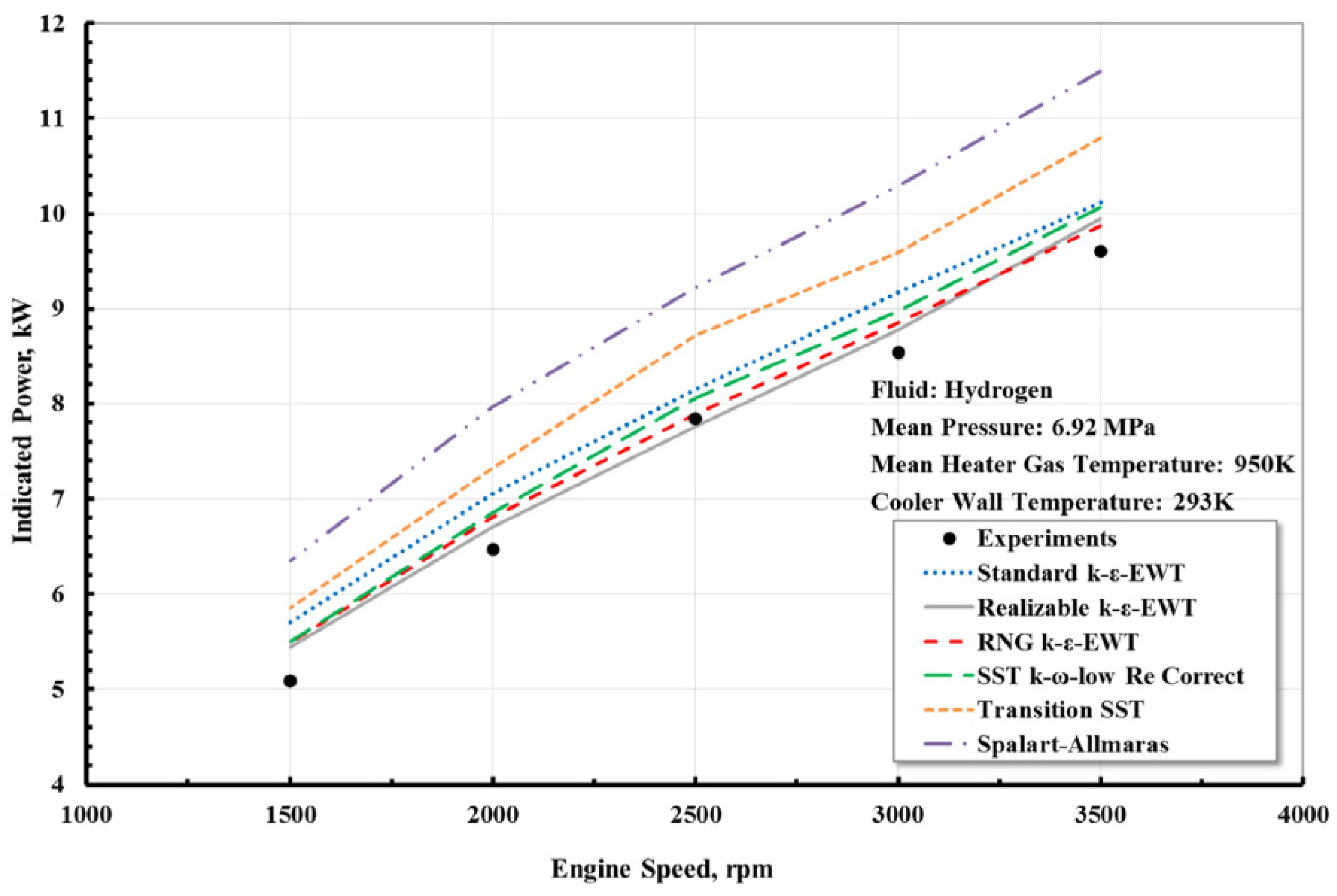
| El-Ghafour et al. (2019) [76] | 3D Turbulent (6 turbulence models) | Compression and expansion spaces, heater, regenerator, cooler and cooler-end connection, displacer | Regenerator as porous media. Sensibility study vs. turbulence model. Realizable k-ε model as most appropriate. Comparison with experiments (power, thermal efficiency) in GPU-3 engine |
| Chi et al. (2020) [77] | 2D Laminar | Expansion and compression chambers, heat exchangers, and regenerator. | Free-piston Stirling engine. Regenerator simulated as porous media. Compares output power and heating power with experiments |
| Cheng and Chen (2017) [78] | 3D Turbulent (k-ε standard) | Expansion chamber, regenerator, cooler, heater tubes, displacer, and compression chamber | Regenerator simulated as porous media. Simulates the whole SE. Comparison with experimental power with qualitative agreement |
| Castro Caetano et al. (2019) [79] | 3D Turbulent (SST k-ω) | Displacer, compression and expansion chambers (The displacer walls are considered as a conductor using ANSYS® Fluent function “shell conduction”) | Specific approach to derive initial and boundary conditions for transient simulation. Includes radiation. Compares with engine power measurements |
| Rogdakis et al. (2019) [80] | 3D Turbulent (realizable k-ε) | Piston, displacer, compression and expansion space, heater tubes, regenerator, and cooler tubes | Simulation of one-eighth of the geometry. Regenerator as a porous medium. No comparison with experiments |
| Bitsikas et al. (2020) [81] | 3D Turbulent (realizable k-ε) | Compression and expansion spaces, hot and cold heat exchangers, regenerator | Same geometry as [80]. Focus on heat transfer in regenerator, which is divided in several sections. Correlations development. No comparison with experiments |
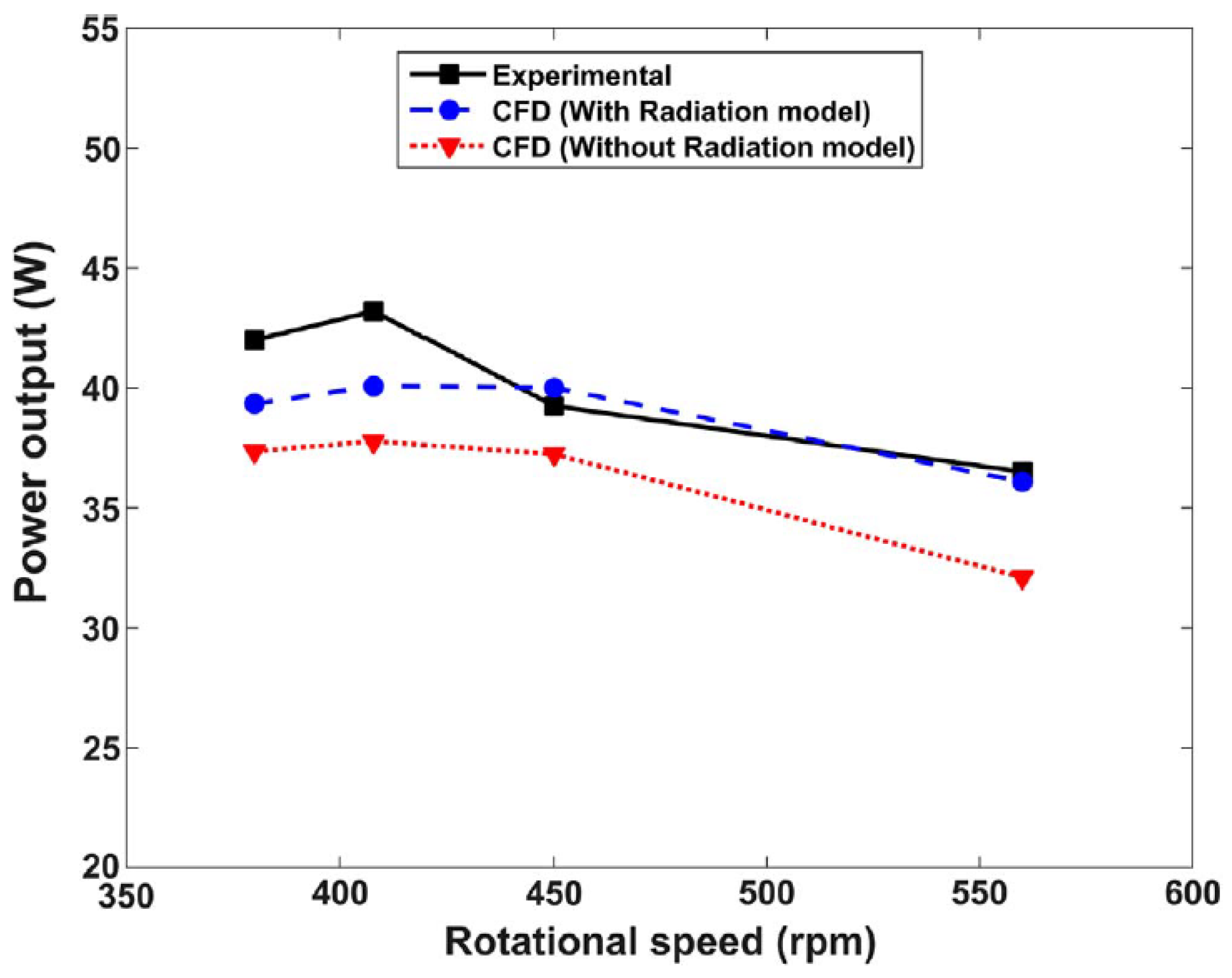
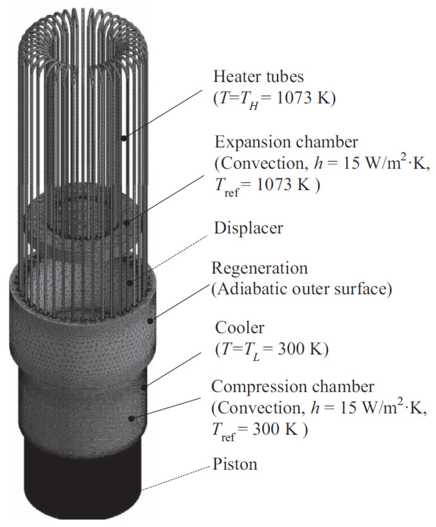
| Ben Mansour et al. (2017) [82] | 2D Turbulent (k-ε standard) | Piston, cylinder, expansion and compression spaces | Focus on the effect of radiation model in engine without regenerator. Comparison with experiments in output power |
| Arslan et al. (2023) [83] | 2D Turbulent (realizable k-ε) | Displacer, regenerator, compression and expansion spaces | Effect of compression ratio on engine performance. No details about regenerator model. Compares with experimental P-V cycle |
| Mohammadi and Jafarian (2018) [62] | 2D Turbulent (SST k-ω) | Displacer, regenerator, compression and expansion spaces | TEMPO and GPU-3 Stirling engines considered. Regenerator as porous media. Compares with experimental P-V cycle |
| Abuelyamen et al. (2017) [84] | 2D Laminar | Displacer, compression and expansion zones | Parametric variation of initially charged pressure, thermal boundary condition, and type of working fluid (real gases). Comparison with experiments of power output [75] |
| Reference | Simulation Type | Simulated Components | Relevant Comments |
|---|---|---|---|
| Abuelyamen and Ben-Mansour (2018) [69] | 2D Laminar | Varying-volume hot and cold cylinders, displacer, piston | Use of radiation model. No details about dynamic mesh treatment. γ-type has the highest power output. No comparison with experiments |
| Regalado-Rodríguez and Militello (2022) [64] | 3D Turbulent (k-ε standard) | Hollow cylindrical chambers with added fins to enhance heat transfer | Focus on minimizing dead volume. Steady-state simulations, displacer/piston at mid-stroke. Combination with 2nd order models. No comparison with experiments |
| Mahkamov (2006) [35] | 3D Turbulent (k-ε standard) | Heater, heater’s manifold, regenerator, coolers, expansion and compression spaces, connecting pipe | Simulated whole Stirling engine (one of the first 3D CFD simulations). Regenerator as porous media. Focus on improving engine design. Comparison with experiments: engine indicated power |
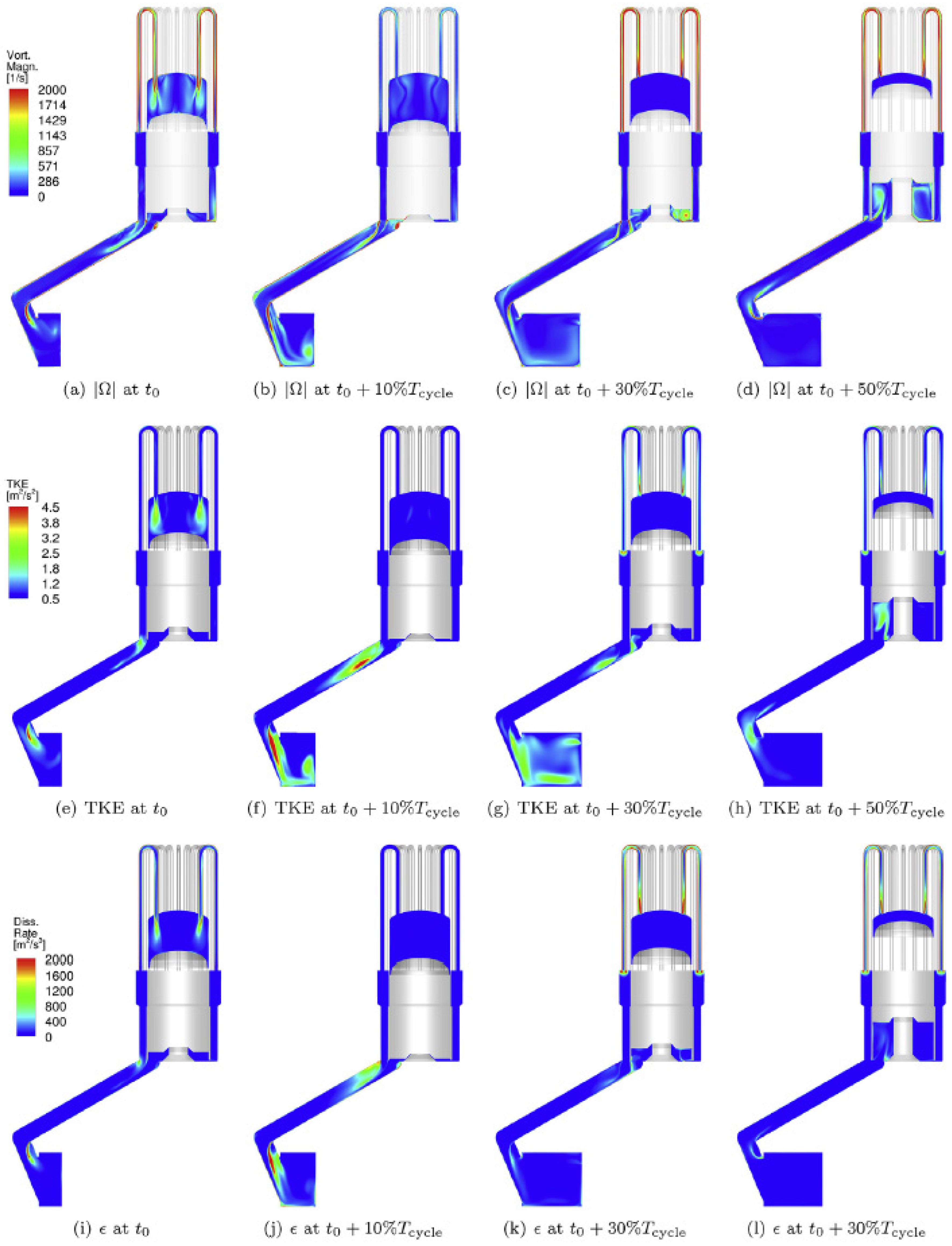
| Kuban et al. (2019) [34] | 3D Turbulent (realizable k-ε and SST k-ω) | Cylinder volume, heater tubes, tube connecting both cylinders and regenerator | Regenerator as porous media. Sensibility study vs. turbulence model. Shows contours of turbulent variables and vorticity. Comparison with experiments: power as function of heater temperature |
| Kato et al. (2017) [61] | 2D Steady Turbulent (k-ε standard) | Space below the hot side displacer within regenerator | Piston motion was neglected. Focus on relation between inlet, average, and heat exchanger temperatures. Compares with experiment’s P-V diagram |
| Chen (2017) [59] | 3D Laminar | Piston, displacer, expansion and compression chambers | Focused on effect of piston and displacer geometrical arrangement. In-house software. Compares with experiment’s P-V diagram |
| Chen et al. (2014) [33] | 3D Laminar | Piston, displacer, expansion and compression chambers | Focused on heat transfer evolution in one engine cycle. In-house software. No comparison with experiments |
| Chen et al. (2018) [33] | 3D Turbulent (SST k-ω) | Piston, displacer, expansion and compression chambers | Modification of displacer cylinder with grooves to enhance heat transfer. Compares with experiment’s P-V diagram as in [59] |
| Chen et al. (2015) [60] | 3D Laminar | Piston, displacer, expansion and compression chambers | Parametric variation of various geometrical and operational parameters. In-house software. No comparison with experiments |
| Alfarawi et al. (2016) [32] | 2D Laminar | Heater, displacer, regenerator, cooler, connecting pipe, and power piston | Regenerator and cooler as a porous media. Compares with experiment’s P-V diagram. |
Disclaimer/Publisher’s Note: The statements, opinions and data contained in all publications are solely those of the individual author(s) and contributor(s) and not of MDPI and/or the editor(s). MDPI and/or the editor(s) disclaim responsibility for any injury to people or property resulting from any ideas, methods, instructions or products referred to in the content. |
© 2024 by the authors. Licensee MDPI, Basel, Switzerland. This article is an open access article distributed under the terms and conditions of the Creative Commons Attribution (CC BY) license (https://creativecommons.org/licenses/by/4.0/).
Share and Cite
Laín, S.; Villamil, V.; Vidal, J.R. CFD Simulation of Stirling Engines: A Review. Processes 2024, 12, 2360. https://doi.org/10.3390/pr12112360
Laín S, Villamil V, Vidal JR. CFD Simulation of Stirling Engines: A Review. Processes. 2024; 12(11):2360. https://doi.org/10.3390/pr12112360
Chicago/Turabian StyleLaín, Santiago, Valentina Villamil, and Juan R. Vidal. 2024. "CFD Simulation of Stirling Engines: A Review" Processes 12, no. 11: 2360. https://doi.org/10.3390/pr12112360
APA StyleLaín, S., Villamil, V., & Vidal, J. R. (2024). CFD Simulation of Stirling Engines: A Review. Processes, 12(11), 2360. https://doi.org/10.3390/pr12112360