Review

Review of Research Progress on Acoustic Test Equipment for Hydrate-Bearing Sediments

1
State Key Laboratory of Offshore Natural Gas Hydrates, Beijing 102209, China
2
Sanya Offshore Oil & Gas Research Institute, Northeast Petroleum University, Sanya 572025, China
3
CNOOC Research Institute Ltd., Beijing 100028, China
*
Author to whom correspondence should be addressed.
Processes 2024, 12(11), 2337; https://doi.org/10.3390/pr12112337
Submission received: 18 September 2024 / Revised: 15 October 2024 / Accepted: 23 October 2024 / Published: 24 October 2024

Abstract

:
When acoustic waves propagate through hydrate samples, they carry extensive information related to their physical and mechanical properties. These details are comprehensively reflected in acoustic parameters such as velocity, attenuation coefficient, waveform, frequency, spectrum, and amplitude variations. Based on these parameters, it is possible to invert the physical and mechanical indicators and microstructural characteristics of hydrate samples, thereby addressing a series of issues in hydrate development engineering. This study first provides an overview of the current applications and prospects of acoustic testing in hydrate development. Subsequently, it systematically elaborates on the progress in research on acoustic testing systems for hydrate samples, including the principles of acoustic testing, ship-borne hydrate core acoustic detection systems, laboratory hydrate sample acoustic testing systems, and resonance column experimental systems. Based on this foundation, this study further discusses the development trends and challenges of acoustic testing equipment for hydrate-bearing sediments.

1. Introduction

Natural gas hydrates are crystalline substances formed by the combination of natural gas and water under high-pressure and low-temperature conditions [1,2]. Due to their ice-like appearance and flammability upon exposure to heat, they are also known as “flammable ice”. Natural gas hydrates are widely distributed in nature, being primarily found in permafrost regions (<10%) and continental margin basins (≥90%). The total methane reserves in natural gas hydrates [3] are estimated to be approximately 2 × 10¹⁶ m3, which is twice the total carbon stored in traditional fossil fuels (coal, oil, natural gas, etc.) [4]. It is estimated that globally recoverable hydrate resources could meet human energy needs for the next 200 years [5,6,7], highlighting their significant potential in alleviating the energy crisis and improving air quality [8,9].
However, achieving the long-term and large-scale commercial exploitation of natural gas hydrates still faces numerous challenges, including reservoir heterogeneity, immature exploration and development technologies, and potential geological engineering risks [10,11,12], all of which hinder the safe development of hydrate resources. Among these challenges, geological engineering risks primarily include issues such as sand production [13,14,15], reservoir instability [16], submarine landslides [17,18], methane leakage [19], and slope instability [1,20]. In terrestrial areas, the environmental problems associated with geohazards caused by the dissociation of hydrates should likewise not be ignored [21,22,23]. Clarifying the quantitative relationship between hydrate properties and geological engineering risks is crucial. The early exploration of the physical and mechanical properties of hydrates relied on geophysical observations and in situ overpressure coring tests due to technological and equipment limitations [24,25,26,27,28]. With the development of experimental laboratory techniques and equipment, many researchers have shifted their focus to indoor experiments [29]. Establishing indoor simulation devices for hydrate property testing and conducting large-scale indoor experiments have accelerated the exploration of the physical and mechanical properties of hydrates, thereby promoting the evolution of commercial hydrate development [29].
Acoustic testing, as a fast, non-destructive, and convenient method, possesses unique advantages in hydrate property testing. When acoustic waves interact with hydrate-bearing sediment, information related to the physical and mechanical parameters and microstructural changes in the medium is carried in the received waves. Consequently, acoustic testing is increasingly utilized in both laboratory and field experiments involving hydrates [30,31,32]. However, hydrate-bearing sediments require strict temperature and pressure conditions for their stable existence [33,34,35], making it challenging to directly use conventional experimental systems for sediment property measurements. As a result, numerous research institutes have embarked on the development of acoustic experimental systems for hydrate-bearing sediments, laying the foundation for studying their physical and mechanical behaviors.
The purpose of this study is to comprehensively summarize the current application status of acoustic testing systems for hydrate-bearing sediments, explore the prospects of these systems in the field, and enhance their application. We first summarize, analyze, and evaluate the current research progress on acoustic testing systems for hydrate-bearing samples and identify the deficiencies of current acoustic testing equipment. Based on these analyses, the development trends, challenges, and future prospects of acoustic testing equipment for hydrate-bearing samples are discussed and forecasted.

2. Application Status and Prospects of Acoustic Testing in Hydrate Development

When acoustic waves propagate through sediment, they carry abundant information related to the physical and mechanical properties of the sediment. By analyzing dynamic indicators of the acoustic waves such as intensity (amplitude), attenuation, and kinematic features like velocity and phase changes, it is possible to invert the physical and mechanical indicators and microstructural characteristics of hydrate sediments. The application status and prospects of acoustic testing in hydrate development include the following:
(1)
Evaluation of hydrate development strata integrity and wellbore stability (determination of the reservoir state through changes in acoustic signals);
(2)
Geological stratification and saturation determination of hydrate reservoirs;
(3)
Seismic response analysis and bottom simulating reflector (BSR) identification (identification of BSR through the difference in wave velocity between hydrates and free gas layers);
(4)
Calculation of the dynamic Young modulus, shear modulus, and Poisson’s ratio of hydrate samples;
(5)
Establishment of correlations between the acoustic parameters of hydrate samples and geotechnical parameters using correlation analysis;
(6)
Identification of the fractures and characterization of anisotropy in hydrate reservoirs;
(7)
Description of the internal crack development and evolution laws under loading conditions in hydrate samples;
(8)
Study of the damage evolution equations and constitutive relationships under the uniaxial, triaxial, and creep tests of hydrate samples;
(9)
Analysis of porous medium fluid flow effects in hydrate reservoirs;
(10)
Inversion of the physical parameters of hydrate reservoirs such as porosity, density, pressure, temperature, and fracture.

3. Research Progress of Hydrate Acoustic Testing Systems

Hydrate acoustic testing systems offer significant advantages and are widely applied in both laboratory and field settings. These systems are categorized as follows based on the frequency of the acoustic waves used: bend element testing systems (high-frequency sound waves of 0.02~1 MHz) and resonance column testing systems (low-frequency sound waves of 10~1000 kHz).

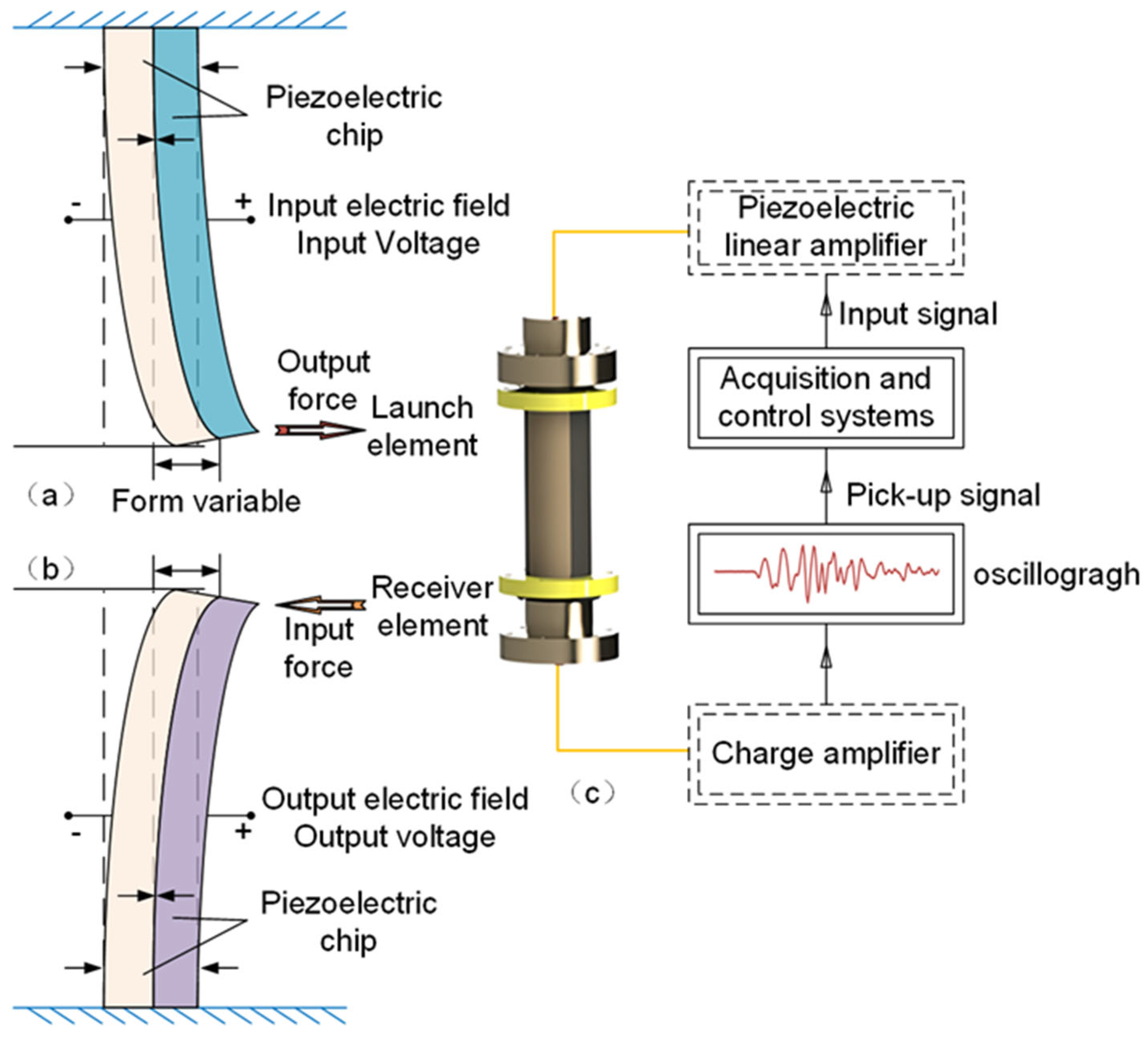
3.1. Bend Element Testing Systems

Bend element testing systems are characterized by their simple structure and low cost, making them the most commonly used experimental equipment in laboratories for measuring the velocity of hydrate samples [36]. The core of the bend element testing system is the bending element, which is made from piezoelectric ceramic bilayers. When one end of the bilayers receives an excitation voltage, the entire element bends due to the piezoelectric effect, emitting a sound signal (Figure 1a). Conversely, when the piezoelectric element undergoes forced bending deformation, it generates a voltage due to the inverse piezoelectric effect, allowing the reception of electrical signals (Figure 1b).
Utilizing this bending element characteristic, the bend element system consists of two separate piezoelectric ceramic bending elements placed at both ends of a hydrate sample, with one serving as the transmitting element and the other as the receiving element. When an electrical signal is applied at one end (the top or bottom of the sample), the bending element deforms and emits a signal, perturbing the sediment in wave form. This disturbance propagates through the sediment and is captured by the receiving element at the opposite end, converting it back into an electrical signal, thereby completing the sediment velocity measurement experiment. Both bending elements are connected to signal amplifiers to ensure clear signal recording during signal input and output. Data acquisition and control devices manage signal emission, reception, and experiment information storage and recording (Figure 1c). Bend element testing systems are widely used for on-site acoustic measurements of pressure core samples and indoor experimental research.

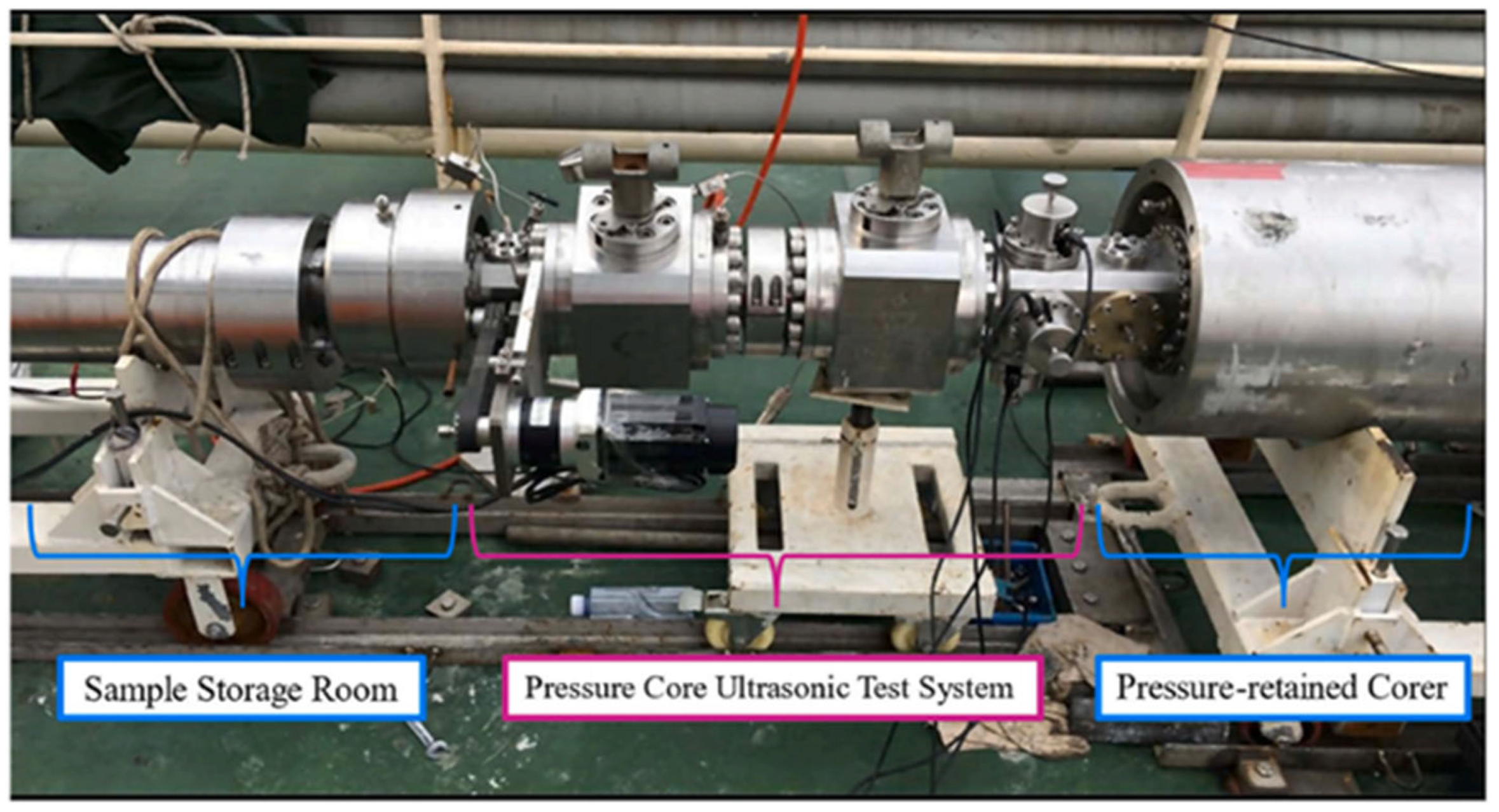
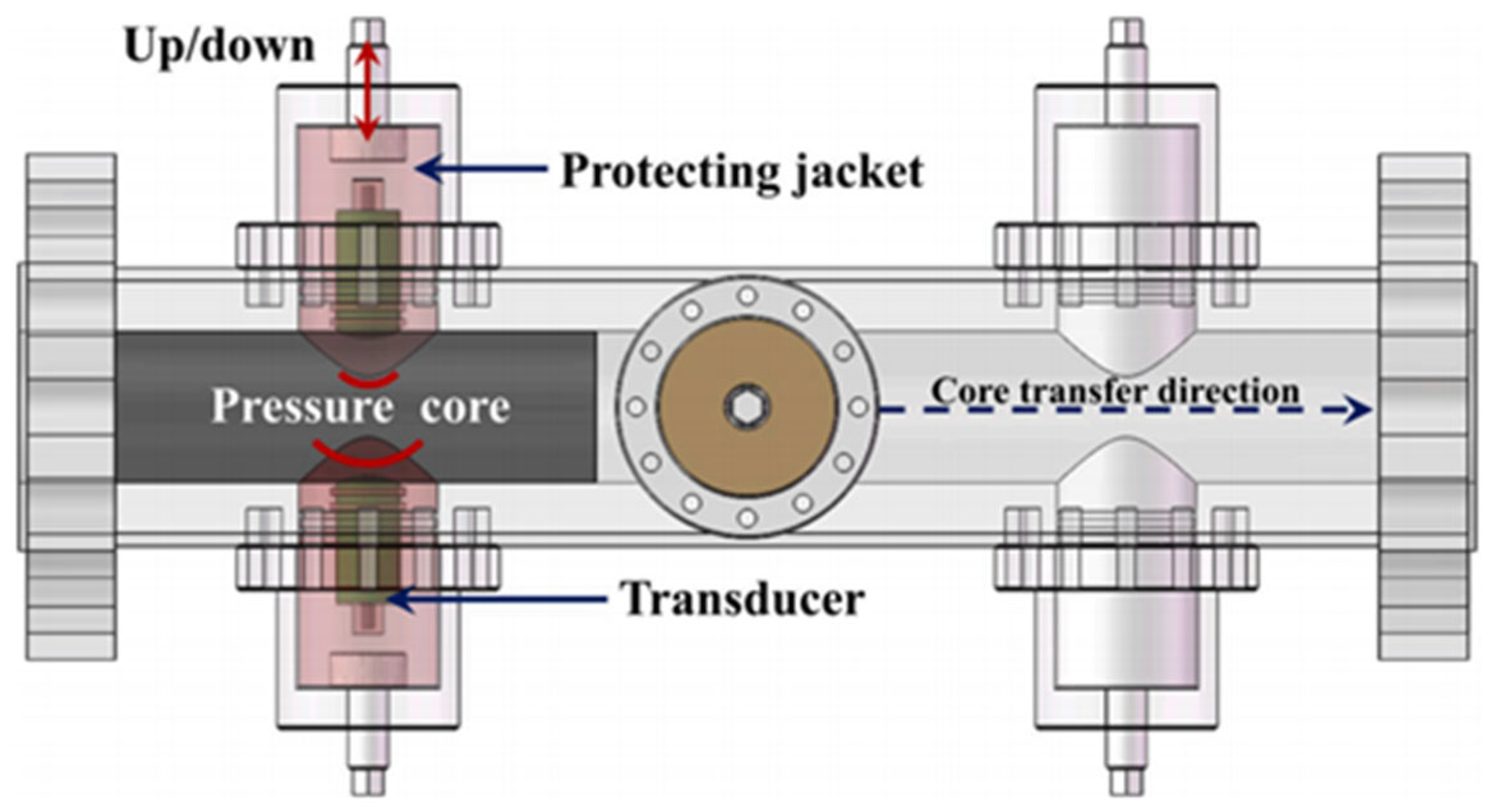
3.1.1. Shipboard Hydrate Core Acoustic Detection Systems

Research groups in Europe, America, and Japan are pioneers in the study of shipboard hydrate pressure core detection technology, establishing multiple integrated detection systems and corresponding analytical methods for hydrate pressure core samples. These advancements include the MALLIK Mobile Core Laboratory designed by Anadarko Petroleum Corporation [38]. Independently developed by the Georgia Institute of Technology, the Instrumented Pressure Testing Chamber (IPTC) [39] and PCUTS [40] not only integrate acoustic detection modules but also incorporate resistivity testing modules. However, due to structural limitations, these devices cannot provide axial loading capability to the specimen. This also means that they cannot carry out triaxial mechanical experiments. Figure 2 illustrates the physical connection between PCUTS and pressure core retrieval equipment.
Subsequently, the Pressure Core Analysis and Transfer System (PCATS), developed by Geotek Ltd. in the Daventry, UK, was designed to facilitate the transfer of cores under pressure conditions. PCATS features a triaxial configuration that allows in situ acoustic and large-strain rock mechanics testing, as well as the direct measurement of permeability [41]. Details of the sample transfer and testing methodologies can be found in the references [42,43]. Building upon PCATS, the Pressure-core On-board Transfer and Analysis System (POTAS) was jointly developed by the Dalian University of Technology and Zhejiang University (Figure 3) [44]. This system utilizes acoustic transducers with a self-coupled curved end-face design, adjustable based on the curvature facing the diameter of hydrate-bearing cores to accommodate various sample sizes. POTAS also includes a reserved connection port for CT scanning units. The open internal threaded connection end can be directly sealed onto the CT scanning unit, meeting the integrated detection requirements of CT scanning and ultrasonic testing.

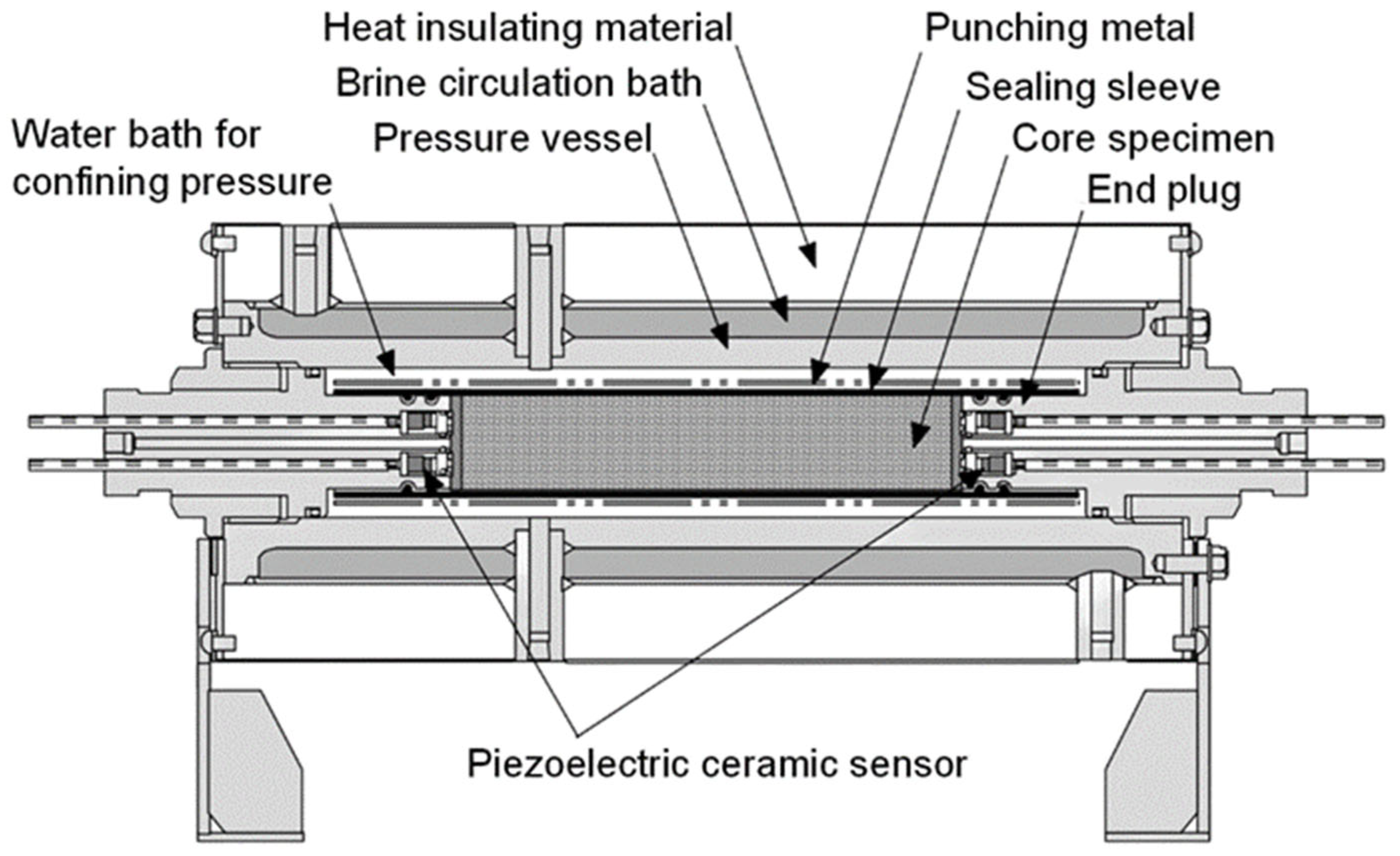
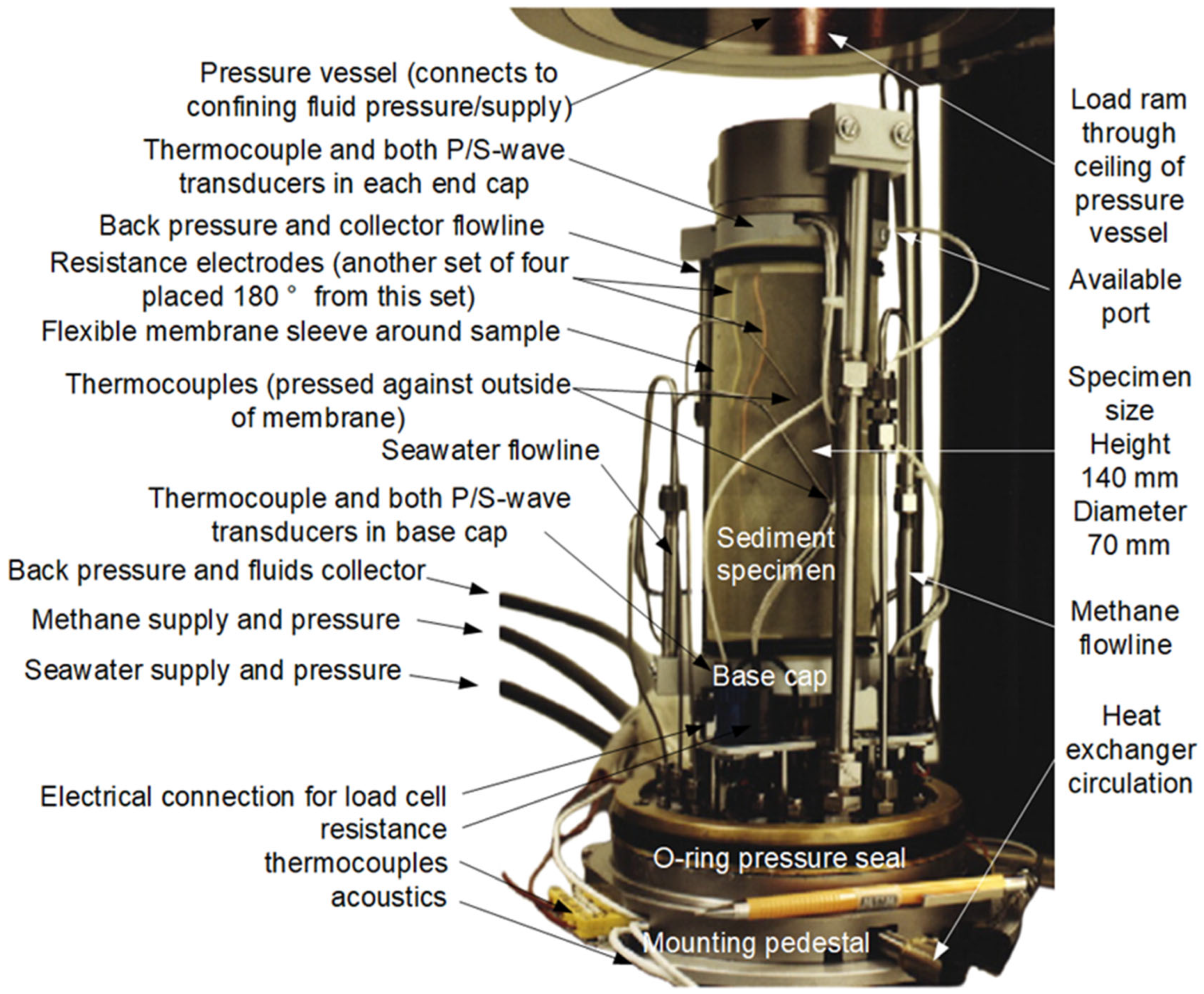
3.1.2. Laboratory Hydrate Sample Acoustic Testing Systems

Based on the foundation of the bending element test system, various research institutions have successively developed multiple indoor acoustic testing systems suitable for hydrate-bearing samples. These indoor hydrate sample acoustic testing systems primarily consist of five components: a gas injection system, reaction vessel, temperature control system, gas recovery system, and data acquisition system. The experimental setups can be categorized structurally into one-dimensional, multi-dimensional, and integrated indoor hydrate sample acoustic testing systems.
  • One-dimensional indoor hydrate sample acoustic testing systems
The National Institute of Advanced Industrial Science and Technology (AIST) in the United States developed an indoor hydrate sample acoustic testing system [45], as depicted in Figure 4. This device includes insulation layers, a circulating saltwater bath, a confining pressure fluid layer, and the sample itself, capable of withstanding pressures of up to 25 MPa. The sediment sample is centrally located within the apparatus, enclosed in a rubber barrel, with piezoelectric ceramic sensors positioned at both ends. This setup enables acoustic measurements on Φ 50 × 160 mm2 hydrate samples during their in situ synthesis and decomposition processes. Similar acoustic testing systems have also been developed by the Dalian University of Technology [46] and the Indian Institute of Technology [47].
In conventional one-dimensional indoor hydrate sample acoustic testing systems, acoustic transducers are typically positioned at both ends of the sample, and these positions are fixed. However, to accommodate samples of different lengths, a clamping device can be installed at both ends of the sample to adjust the distance between the acoustic transducers [48,49,50]. Simultaneously, the clamping device can compact the sample and apply initial axial stress, ensuring close contact between the acoustic transducers and the sediment, thereby improving the quality of acoustic measurements. This clamping device structure (Figure 5) allows for clamping at one end or both ends [51,52].
  • Multi-dimensional Indoor Hydrate Sample Acoustic Testing Systems
In the realm of indoor hydrate sample acoustic testing systems, the conventional setups are typically limited to capturing one-dimensional acoustic parameters due to structural constraints. However, in the processes of hydrate formation and decomposition, it becomes crucial to ascertain specific details such as the location and extent of decomposition, which are difficult to achieve solely based on one-dimensional acoustic parameters. To address this challenge, the China University of Petroleum has developed a multi-dimensional indoor hydrate sample acoustic testing system where the hydrate reaction vessel is equipped with three sets of opposing acoustic probes, enabling separate measurements of hydrate wave velocities at different layers [53,54]. Taking this concept further, the Qingdao Institute of Marine Geology [55] has pioneered a two-dimensional imaging indoor hydrate sample acoustic testing system, as illustrated in Figure 6. This device incorporates four pairs of piezoelectric ceramic sensors, each transmitting and receiving signals using cross-transmission methods (where signals transmitted by each probe can be simultaneously received by 4 sensor probes, resulting in 16 waveform files per measurement). Finally, through tomographic imaging techniques, the acoustic data are processed to generate two-dimensional acoustic profiles within the sediment, facilitating a comprehensive “3D” mesh analysis of hydrate variations during the formation and decomposition processes.
Currently, established acoustic measurement devices effectively characterize the overall geophysical properties of hydrate-bearing sediment samples. However, there are still shortcomings in describing local and microscopic variations. Even with the application of two-dimensional acoustic imaging technology, the characterization accuracy remains noticeably low. Therefore, the development of more advanced acoustic tomography imaging technology is crucial for future research on defect localization and microscopic evolution within hydrate-bearing sediment samples.
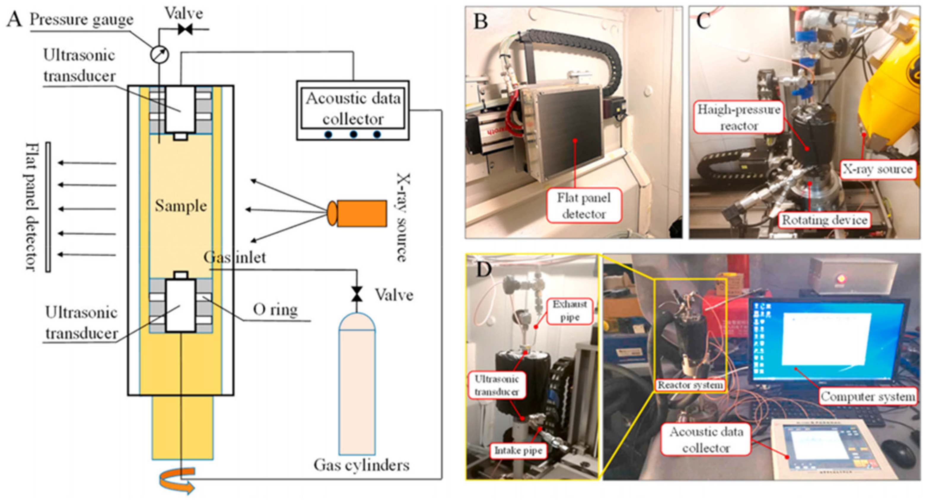
  • Hydrate Sample Combined Acoustic Detection System
To obtain more comprehensive physical parameters of hydrate samples, various research institutions have integrated multiple measurement techniques into indoor hydrate sample acoustic detection systems. Researchers such as Hu Gaowei and Ye Yuguang [56,57,58,59,60] from the Qingdao Institute of Marine Geology, China Geological Survey, have integrated time-domain reflectometry (TDR) into indoor acoustic testing systems for investigating the geophysical properties of hydrate-bearing samples (Figure 7). In the experimental setup, a pair of piezoelectric ceramic sensors are placed at both ends of the Φ 68 × 150 mm2 hydrate sample within the main reaction vessel to monitor acoustic behavior. The TDR measurement system consists of a TDR detector and two TDR probes. One TDR probe is a metal ring embedded in a slot on the inner wall of a polytetrafluoroethylene cylinder, while the other is a metal cylinder inserted into the center of the sample. The TDR measurement system identifies changes in characteristic impedance within the sediment and calculates hydrate saturation using empirical formulas. The introduction of the TDR measurement system enhances the accuracy of hydrate saturation identification, thereby establishing a more precise correlation between hydrate saturation and its acoustic properties.
Similarly, to enhance the accuracy of saturation identification, institutions such as the China University of Petroleum (East China) [61], Peking University [62], and Chengdu University of Technology [63] have integrated resistivity testing modules into indoor hydrate sample acoustic testing systems.
The Qingdao Institute of Marine Geology, China Geological Survey [64,65], has developed an acoustic-triaxial integrated testing system, as shown in Figure 8. In addition to basic acoustic testing, this system includes an axial load application device, allowing acoustic measurements under triaxial stress conditions for Φ 39 × 120 mm2 samples and synchronized acoustic measurements during creep loading stages. This approach closely simulates actual reservoir conditions and operational scenarios during development.
The U.S. Geological Survey Woods Hole Science Center [66,67] has integrated multiple testing modules into an indoor hydrate sample acoustic testing system and developed a comprehensive hydrate sample testing apparatus, as depicted in Figure 9, which includes temperature testing modules, resistivity testing modules, and more. These advancements provide a more comprehensive characterization of the physical properties of hydrate samples.
The above hydrate sample combined acoustic detection system is still considered as a black box experimental system, where it is not possible to directly observe fine changes in hydrate samples during research. Therefore, the Qingdao Institute of Marine Geology [68,69,70] integrated X-ray CT with an acoustic measurement system to establish a joint hydrate CT–acoustic testing system for hydrate-bearing sediments (Figure 10). The sample chamber is made of PEEK material, which facilitates X-ray penetration and improves the imaging quality. Based on this system, experiments related to microscopic structural changes in hydrates can be conducted, enhancing the understanding of internal microstructural changes in hydrate samples.

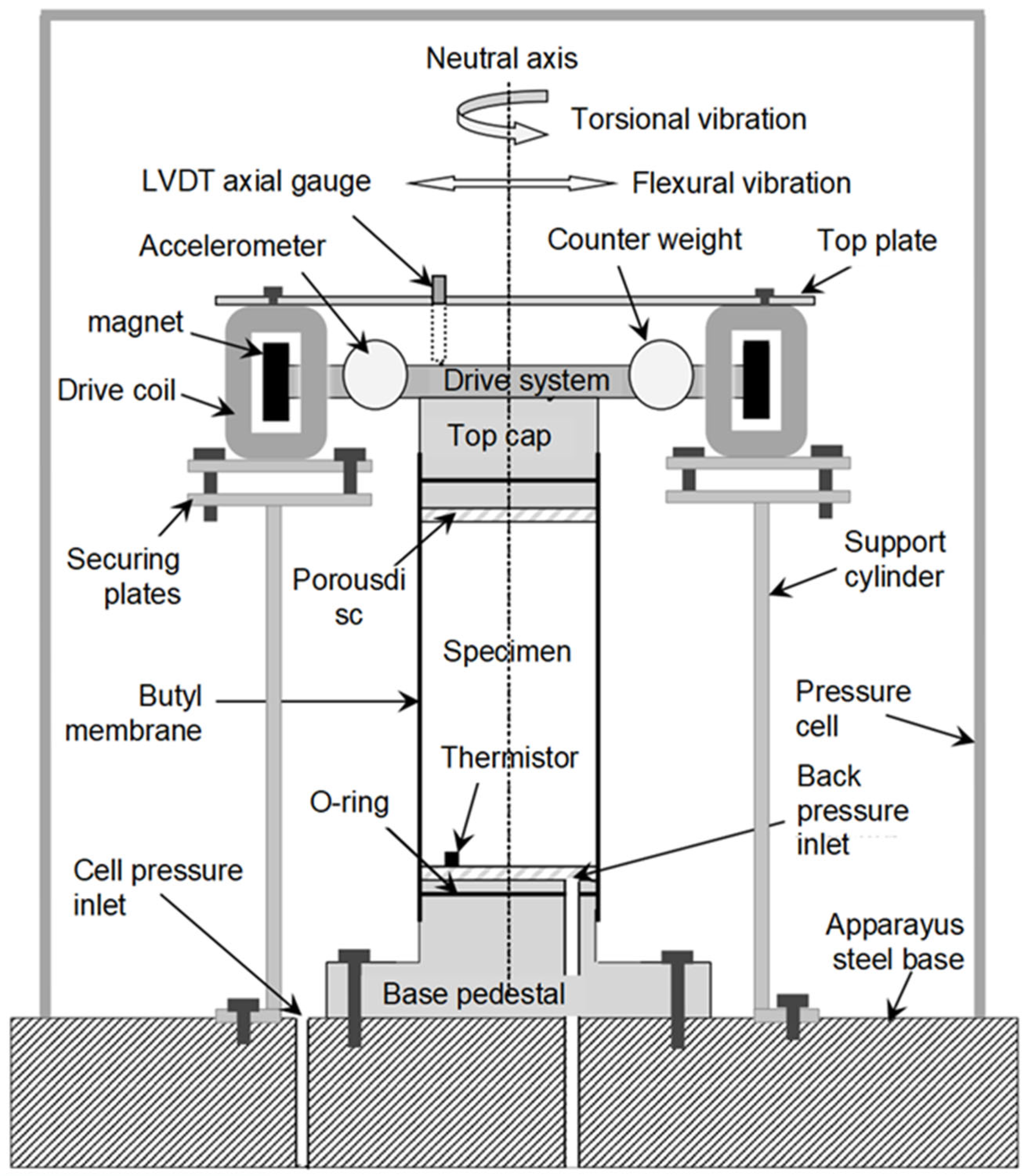
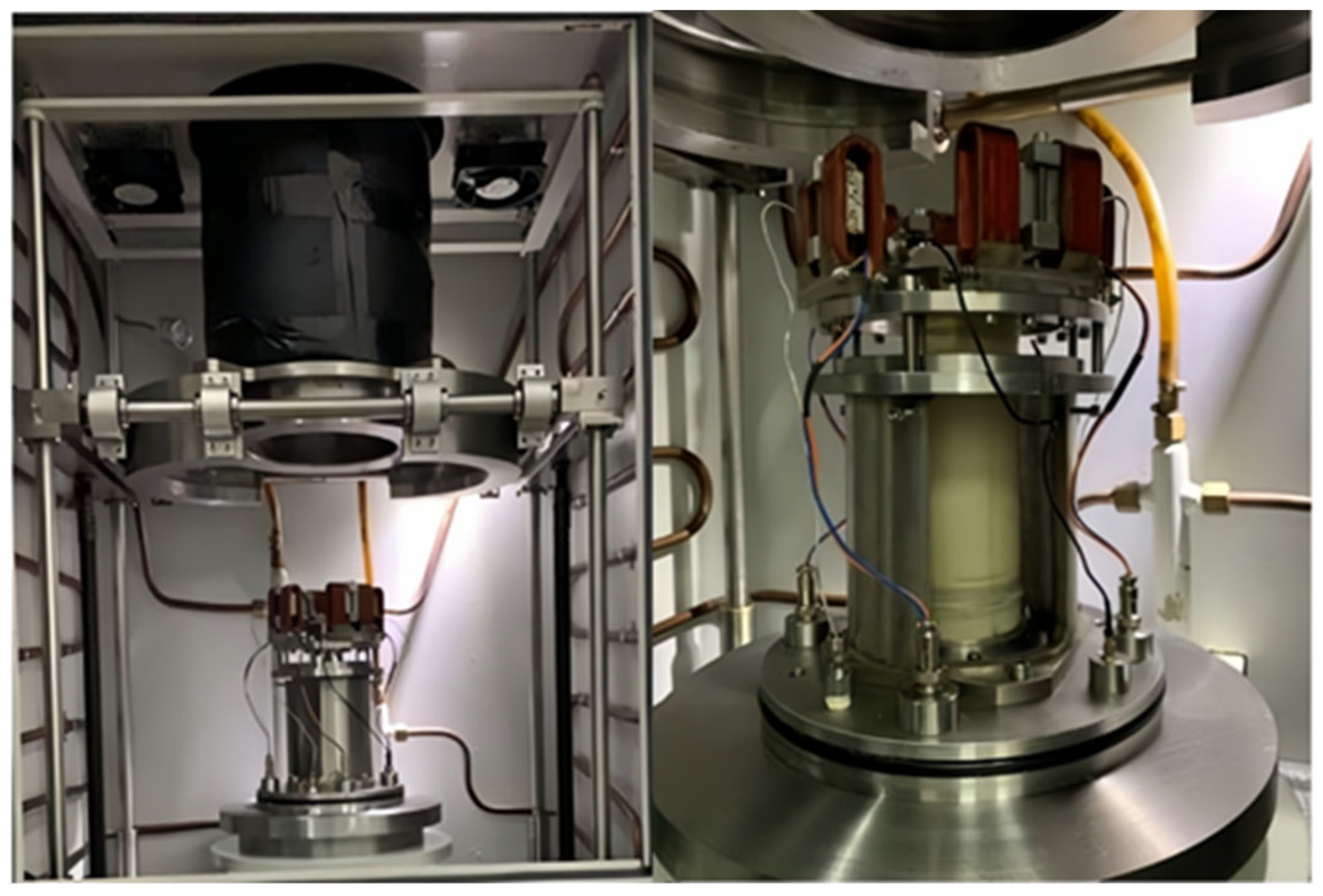
3.2. Resonant Column Experiment System

Resonant column testing allows for the measurement of the acoustic parameters of hydrate-bearing samples at close to seismic frequencies (<500 Hz), making it highly relevant for interpreting field data [71,72]. This testing method is based on the principle of resonance [73]. When sediment is subjected to periodic external forces, resonance occurs if the frequency of the external force matches or is close to the natural frequency of the sediment. At resonance, the sediment reaches maximum amplitude, maximizing energy transfer efficiency [74,75]. By monitoring the vibration frequency and amplitude of the sediment, the acoustic properties of the sediment can be obtained [76,77].
The University of Southampton modified an unfixed Stokoe-type resonant column apparatus [78] to meet the testing requirements of hydrate-bearing samples. They incorporated a specialized resonant column testing system for the acoustic measurements of hydrate samples, adding features such as a low-temperature coolant and a high-pressure chamber [79,80,81,82], as shown in Figure 11. This setup enables acoustic resonance testing of Φ 70 × 140 mm2 samples. During acoustic measurements, an electromagnetic field is induced by applying voltage to the driving coil, causing the magnet to rotate or move linearly, thereby driving the connected mechanism to generate torsional or bending vibrations in the sediment. Subsequently, the frequency and amplitude of the applied voltage are adjusted stepwise to match the resonance frequency of the sample and its attached driving mechanism. Based on the resonance frequencies and wave attenuation characteristics of the bending and torsional vibrations, the acoustic properties of the sediment are calculated [80].
Researchers from the University of Waterloo in Canada [80] and the Qingdao Institute of Marine Geology [84] (Figure 12) have similarly developed and designed acoustic measurement devices for hydrate-bearing sediments based on resonance column testing systems. The principles and structures of these devices are largely similar to those of the aforementioned systems. These instruments play a crucial role in exploring the geophysical properties of hydrate-bearing sediment samples.
Currently, the application uses the above equipment to obtain a complete sonic curve, through which sediment wave velocity, wave impedance, and elasticity parameters can be calculated to characterize the stratigraphic properties [85]. The difference in wave velocity can also be used to recognize BSR and determine whether there is hydrate endowment [86]. Through the continuous wave velocity curve, the formation state can be detected [87].

4. Conclusions and Outlook

Acoustic testing, as a rapid, non-destructive, and straightforward detection method, extracts acoustic parameters to reflect the physical and mechanical properties of hydrate-bearing sediment samples. This paper systematically summarizes the progress made in the research on hydrate acoustic testing devices and draws the following conclusions:
(1)
Acoustic testing is a non-destructive method that can be widely applied in various fields of hydrate testing. It indirectly extracts the physical and mechanical properties of hydrate-bearing sediment samples and holds promising development prospects.
(2)
Currently, established acoustic measurement devices effectively characterize the overall geophysical properties of hydrate samples. However, there is still a lack of description regarding local and microscopic variations. Even with the application of two-dimensional acoustic imaging technology, the characterization accuracy remains notably low. Therefore, developing higher-level acoustic tomography imaging technology is crucial for accurately locating internal defects and studying the microscopic evolution of hydrate samples in the future.
(3)
Feasibility studies of four-dimensional ultrasonic testing are recommended. Establishing a four-dimensional ultrasonic testing system to extract parameters such as velocity, travel time, amplitude, AVO (amplitude versus offset) response, impedance, and reflectivity can provide higher-level monitoring and analysis of fluid movement patterns, pressure, and temperature changes during hydrate formation or decomposition. This approach allows for a more systematic and detailed analysis of microscopic structural changes.
(4)
The application of acoustic emission technology, as an important branch of acoustic measurement, has rarely been reported for hydrate-bearing samples. This technology holds great potential for monitoring grain dislocation movement, crack propagation, and evolution within hydrate-bearing samples and has significant practical implications for the future development of hydraulic fracturing for increased production from hydrate resources.
Finally, it is worth mentioning that the purpose of this study is not to compare the gap between the different equipment in the acoustic study of hydrates. Rather, it is to describe the process of equipment development in hydrate acoustic research, ranging from the earliest individual acoustic measurements to the integration of different tools to enrich hydrate acoustic study, demonstrating the process of micro-detail refinement. Finally, we propose directions for the development of hydrate acoustic equipment, including four-dimensional ultrasonic testing and the application of acoustic emission technology, as well as the objective prospects of acoustics for multi-scenario applications in hydrate research. We hope that through this study, we can promote the advancement of hydrate acoustic equipment and research and better serve the safe production of hydrates.

Funding

This research was funded by the Open-ended Fund of the State Key Laboratory of National Gas Hydrates, grant number 2022-FKJJ-SHW.

Conflicts of Interest

Authors Xiaohan Zhang and Yunjian Zhou was employed by the company CNOOC Research Institute Ltd. The remaining authors declare that the research was conducted in the absence of any commercial or financial relationships that could be construed as a potential conflict of interest.

References

  1. Mienert, J.; Vanneste, M.; Bünz, S.; Andreassen, K.; Haflidason, H.; Sejrup, H.P. Ocean warming and gas hydrate stability on the mid-Norwegian margin at the Storegga Slide. Mar. Pet. Geol. 2005, 22, 233–244. [Google Scholar] [CrossRef]
  2. Sloan, E.D. Fundamental principles and applications of natural gas hydrates. Nature 2003, 426, 353–359. [Google Scholar] [CrossRef] [PubMed]
  3. Boswell, R. Is Gas Hydrate Energy Within Reach? Science 2009, 325, 957–958. [Google Scholar] [CrossRef] [PubMed]
  4. Liu, Z.; Lu, Y.; Cheng, J.; Han, Q.; Hu, Z.; Wang, L. Geomechanics involved in gas hydrate recovery. Chin. J. Chem. Eng. 2019, 27, 2099–2106. [Google Scholar] [CrossRef]
  5. Makogon, Y.F. Natural gas hydrates—A promising source of energy. J. Nat. Gas Sci. Eng. 2010, 2, 49–59. [Google Scholar] [CrossRef]
  6. Wu, P.; Li, Y.; Sun, X.; Liu, W.; Song, Y. Mechanical Characteristics of Hydrate-Bearing Sediment: A Review. Energy Fuels 2021, 35, 1041–1057. [Google Scholar] [CrossRef]
  7. Makogon, Y.; Holditch, S.; Makogon, T. Natural gas-hydrates—A potential energy source for the 21st Century. J. Pet. Sci. Eng. 2007, 56, 14–31. [Google Scholar] [CrossRef]
  8. Liu, L.; Sun, Z.; Zhang, L.; Wu, N.; Yichao, Q.; Jiang, Z.; Geng, W.; Cao, H.; Zhang, X.; Zhai, B.; et al. Progress in Global Gas Hydrate Development and Production as a New Energy Resource. Acta Geol. Sin.-Engl. Ed. 2019, 93, 731–755. [Google Scholar] [CrossRef]
  9. Boswell, R.; Collett, T.S. Current perspectives on gas hydrate resources. Energy Environ. Sci. 2011, 4, 1206–1215. [Google Scholar] [CrossRef]
  10. Ning, F.; Yu, Y.; Kjelstrup, S.; Vlugt, T.J.H.; Glavatskiy, K. Mechanical properties of clathrate hydrates: Status and perspectives. Energy Environ. Sci. 2012, 5, 6779–6795. [Google Scholar] [CrossRef]
  11. Wu, N.; Li, Y.; Chen, Q.; Liu, C.; Jin, Y.; Tan, M.; Dong, L.; Hu, G. Sand Production Management during Marine Natural Gas Hydrate Exploitation: Review and an Innovative Solution. Energy Fuels 2021, 35, 4617–4632. [Google Scholar] [CrossRef]
  12. Sun, X.; Yao, D.; Qu, J.; Sun, S.; Qin, Z.; Tao, L.; Zhao, Y. A novel transient hole cleaning algorithm for horizontal wells based on drift-flux model. Geoenergy Sci. Eng. 2024, 233, 212517. [Google Scholar] [CrossRef]
  13. Li, Y.; Hu, G.; Liu, C.; Wu, N.; Chen, Q.; Liu, L.; Li, C. Gravel sizing method for sand control packing in hydrate production test wells. Pet. Explor. Dev. 2017, 44, 1016–1021. [Google Scholar] [CrossRef]
  14. Feng, J.; Yan, T.; Hou, Z. Numerical Simulation Study of Factors Influencing Ultrasonic Cavitation Bubble Evolution on Rock Surfaces during Ultrasonic-Assisted Rock Breaking. Water 2024, 16, 2234. [Google Scholar] [CrossRef]
  15. Li, Y.; Dong, L.; Wu, N.; Nouri, A.; Liao, H.; Chen, Q.; Sun, J.; Liu, C. Influences of hydrate layered distribution patterns on triaxial shearing characteristics of hydrate-bearing sediments. Eng. Geol. 2021, 294, 106375. [Google Scholar] [CrossRef]
  16. Wan, Y.; Wu, N.; Chen, Q.; Li, W.; Hu, G.; Huang, L.; Ouyang, W. Coupled thermal-hydrodynamic-mechanical–chemical numerical simulation for gas production from hydrate-bearing sediments based on hybrid finite volume and finite element method. Comput. Geotech. 2022, 145, 104692. [Google Scholar] [CrossRef]
  17. Jin, G.; Lei, H.; Xu, T.; Liu, L.; Xin, X.; Zhai, H.; Liu, C. Seafloor subsidence induced by gas recovery from a hydrate-bearing sediment using multiple well system. Mar. Pet. Geol. 2019, 107, 438–450. [Google Scholar] [CrossRef]
  18. Yan, C.; Ren, X.; Cheng, Y.; Song, B.; Li, Y.; Tian, W. Geomechanical issues in the exploitation of natural gas hydrate. Gondwana Res. 2020, 81, 403–422. [Google Scholar] [CrossRef]
  19. Misyura, S. Developing the environmentally friendly technologies of combustion of gas hydrates. Reducing harmful emissions during combustion. Environ. Pollut. 2020, 265, 114871. [Google Scholar] [CrossRef]
  20. Bojanowski, M.J.; Oszczypko-Clowes, M.; Barski, M.; Oszczypko, N.; Radzikowska, M.; Ciesielska, Z. Slope destabilization provoked by dissociation of gas hydrates in the Outer Carpathian basin during the Oligocene: Sedimentological, petrographic, isotopic and biostratigraphic record. Mar. Pet. Geol. 2021, 123, 104585. [Google Scholar] [CrossRef]
  21. Farahani, M.V.; Hassanpouryouzband, A.; Yang, J.; Tohidi, B. Insights into the climate-driven evolution of gas hydrate-bearing permafrost sediments: Implications for prediction of environmental impacts and security of energy in cold regions. RSC Adv. 2021, 11, 14334–14346. [Google Scholar] [CrossRef] [PubMed]
  22. Farahani, M.V.; Hassanpouryouzband, A.; Yang, J.; Tohidi, B. Development of a coupled geophysical–geothermal scheme for quantification of hydrates in gas hydrate-bearing permafrost sediments. Phys. Chem. Chem. Phys. 2021, 23, 24249–24264. [Google Scholar] [CrossRef] [PubMed]
  23. Ruppel, C. Permafrost-Associated Gas Hydrate: Is It Really Approximately 1% of the Global System? J. Chem. Eng. Data 2015, 60, 429–436. [Google Scholar] [CrossRef]
  24. Clayton, C.R.I.; Priest, J.A.; Best, A.I. The effects of disseminated methane hydrate on the dynamic stiffness and damping of a sand. Geotechnique 2005, 55, 423–434. [Google Scholar] [CrossRef]
  25. Sun, S.; Zhang, X.; Zhou, Y. Stability Characteristics of Natural Gas Hydrate Wellbores Based on Thermo-Hydro-Mech Modeling. Processes 2024, 12, 2196. [Google Scholar] [CrossRef]
  26. Sun, T.; Wen, Z.; Yang, J.; Yang, K.; Han, Z.; He, J. Analysis of Factors Influencing the Stability of Submarine Hydrate-Bearing Slopes during Depressurization Production. Processes 2024, 12, 679. [Google Scholar] [CrossRef]
  27. Cheng, Y.; Xue, M.; Shi, J.; Li, Y.; Yan, C.; Han, Z.; Yang, J. Numerical Simulating the Influences of Hydrate Decomposition on Wellhead Stability. Processes 2023, 11, 1586. [Google Scholar] [CrossRef]
  28. Lee, C.; Yun, T.S.; Lee, J.-S.; Bahk, J.J.; Santamarina, J.C. Geotechnical characterization of marine sediments in the Ulleung Basin, East Sea. Eng. Geol. 2011, 117, 151–158. [Google Scholar] [CrossRef]
  29. Cheng, K.; Zhang, J.; Miao, Y.; Ruan, B.; Peng, T. The effect of plastic fines on the shear modulus and damping ratio of silty sands. Bull. Eng. Geol. Environ. 2019, 78, 5865–5876. [Google Scholar] [CrossRef]
  30. Lee, J.-W.; Kim, H.; Oh, T.-M. Acoustic Emission Characteristics during Uniaxial Compressive Loading for Concrete Specimens according to Sand Content Ratio. KSCE J. Civ. Eng. 2020, 24, 2808–2823. [Google Scholar] [CrossRef]
  31. Zhang, J.-W.; Murton, J.; Liu, S.-J.; Sui, L.-L.; Zhang, S.; Wang, L.; Kong, L.-H.; Ding, H. Sensitivity and regression analysis of acoustic parameters for determining physical properties of frozen fine sand with ultrasonic test. Q. J. Eng. Geol. Hydrogeol. 2021, 54, qjegh2020-021. [Google Scholar] [CrossRef]
  32. Wang, J.; Li, G.; Kan, G.; Hou, Z.; Meng, X.; Liu, B.; Liu, C.; Lei, S. High frequency dependence of sound speed and attenuation in coral sand sediments. Ocean Eng. 2021, 234, 109215. [Google Scholar] [CrossRef]
  33. Bhutale, S.S.; Dalvi, R.S. Effect of Fines Content on Dynamic Properties of Sand Using Bender Element. In Soil Dynamics: Select Proceedings of 7th ICRAGEE 2020; Springer: Singapore, 2021; pp. 11–22. [Google Scholar]
  34. Sharma, M.; Satyam, N.; Reddy, K.R. Effect of freeze-thaw cycles on engineering properties of biocemented sand under different treatment conditions. Eng. Geol. 2021, 284, 106022. [Google Scholar] [CrossRef]
  35. Liu, T.; Tang, H.; Wu, P.; Wang, H.; Song, Y.; Li, Y. Acoustic characteristics on clayey-silty sediments of the South China Sea during methane hydrate formation and dissociation. Energy 2023, 282, 128978. [Google Scholar] [CrossRef]
  36. Ye, Y. Development of the Experiment Detection Technique In Natural Gas Hydrates: Experimental Techniques and Their Applications; Springer: Berlin/Heidelberg, Germany, 2012; pp. 19–87. [Google Scholar]
  37. Chen, M.; Li, Y.; Merey, Ş.; Wu, N.; Hu, Q.; Zhang, Y.; Dong, L.; Yu, G.; Jiang, H. Review on the Test Methods and Devices for Mechanical Properties of Hydrate-Bearing Sediments. Sustainability 2022, 14, 6239. [Google Scholar] [CrossRef]
  38. Collett, T. Results at Mallik highlight progress in gas hydrate energy resource research and development. Petrophysics 2005, 46, SPWLA-2005-v46n3a6. [Google Scholar]
  39. Santamarina, J.C.; Dai, S.; Jang, J.; Terzariol, M. Pressure Core Characterization Tools for Hydrate-Bearing Sediments. Sci. Drill. 2012, 14, 44–48. [Google Scholar] [CrossRef]
  40. Yang, L.; Zhou, W.; Xue, K.; Wei, R.; Ling, Z. A pressure core ultrasonic test system for on-board analysis of gas hydrate-bearing sediments under in situ pressures. Rev. Sci. Instrum. 2018, 89, 054904. [Google Scholar] [CrossRef]
  41. Schultheiss, P.J.; Francis, T.J.G.; Holland, M.; Roberts, J.A.; Amann, H.; Thjunjoto; Parkes, R.J.; Martin, D.; Rothfuss, M.; Tyunder, F.; et al. Pressure coring, logging and subsampling with the HYACINTH system. Geol. Soc. Lond. Spéc. Publ. 2006, 267, 151–163. [Google Scholar] [CrossRef]
  42. Priest, J.A.; Druce, M.; Roberts, J.; Schultheiss, P.; Nakatsuka, Y.; Suzuki, K. PCATS Triaxial: A new geotechnical apparatus for characterizing pressure cores from the Nankai Trough, Japan. Mar. Pet. Geol. 2015, 66, 460–470. [Google Scholar] [CrossRef]
  43. Priest, J.A.; Hayley, J.L.; Smith, W.E.; Schultheiss, P.; Roberts, J. PCATS triaxial testing: Geomechanical properties of sediments from pressure cores recovered from the Bay of Bengal during expedition NGHP-02. Mar. Pet. Geol. 2019, 108, 424–438. [Google Scholar] [CrossRef]
  44. Li, X.; Jiang, L.; Chu, J.; Zhao, J.; Song, Y. In-situ ultrasonic measurement for hydrate pressure cores sampled by deep sea drilling. Measurement 2023, 221, 113529. [Google Scholar] [CrossRef]
  45. Ebinuma, T.; Suzuki, K.; Nagao, J.; Oyama, H.; Narita, H. Ultrasonic Wave Velocities Associated With Formation and Dissociation of Methane Hydrate in Artificial Sandy Sediments. In Offshore Technology Conference; OTC: Houston, TX, USA, 2008; p. OTC-19260. [Google Scholar] [CrossRef]
  46. Liu, T.; Wu, P.; You, Z.; Yu, T.; Song, Q.; Song, Y.; Li, Y. Deformation characteristics on anisotropic consolidated methane hydrate clayey-silty sediments of the South China Sea under heat injection. Energy 2023, 280, 128190. [Google Scholar] [CrossRef]
  47. Lijith, K.; Rao, R.S.; Singh, D.N. Detection of formation and dissociation of CO2 hydrates in fine-sands through acoustic waves. Fuel 2024, 357, 129802. [Google Scholar] [CrossRef]
  48. Li, F.-G.; Sun, C.-Y.; Zhang, Q.; Liu, X.-X.; Guo, X.-Q.; Chen, G.-J. Laboratory Measurements of the Effects of Methane/Tetrahydrofuran Concentration and Grain Size on the P-Wave Velocity of Hydrate-Bearing Sand. Energy Fuels 2011, 25, 2076–2082. [Google Scholar] [CrossRef]
  49. Zhang, Q.; Li, F.-G.; Sun, C.-Y.; Li, Q.-P.; Wu, X.-Y.; Liu, B.; Chen, G.-J. Compressional wave velocity measurements through sandy sediments containing methane hydrate. Am. Miner. 2011, 96, 1425–1432. [Google Scholar] [CrossRef]
  50. Wang, X.-H.; Li, F.-G.; Xu, Y.-X.; Sun, C.-Y.; Pan, H.; Liu, B.; Yang, L.-Y.; Chen, G.-J.; Li, Q.-P. Elastic properties of hydrate-bearing sandy sediment during CH4–CO2 replacement. Energy Convers. Manag. 2015, 99, 274–281. [Google Scholar] [CrossRef]
  51. Sæther, M.; Almenningen, S.; Ersland, G.; Lunde, P. Compressional wave phase velocity measurements during hydrate growth in partially and fully water saturated sandstone. Fuel 2022, 324, 124522. [Google Scholar] [CrossRef]
  52. Luo, Y.; Peng, J.; Li, P.; He, J.; Li, L. Influence of heterogeneous hydrate distribution on the compressional wave velocity of hydrate-bearing sediment specimens. J. Nat. Gas Sci. Eng. 2015, 22, 90–97. [Google Scholar] [CrossRef]
  53. Zhu, Y.-J.; Huang, X.; Li, H.; Zhu, Y.-J.; Wang, X.-H.; Sun, Y.-F.; Xiao, P.; Sun, C.-Y.; Chen, G.-J. Study on acoustic properties of hydrate-bearing sediments with reconstructed CO2 hydrate in different layers during CH4 hydrate mining. Ultrason. Sonochemistry 2023, 100, 106641. [Google Scholar] [CrossRef]
  54. Zhu, Y.-J.; Yang, X.-M.; Huang, X.; Li, H.; Wang, X.-H.; Sun, Y.-F.; Xiao, P.; Sun, C.-Y.; Chen, G.-J. Acoustic characterization of hydrate formation and decomposition in clay-bearing sediments. Pet. Sci. 2024, 21, 2830–2838. [Google Scholar] [CrossRef]
  55. Bu, Q.; Hu, G.; Ye, Y.; Liu, C.; Li, C.; Wang, J. Experimental study on 2-D acoustic characteristics and hydrate distribution in sand. Geophys. J. Int. 2017, 211, 990–1004. [Google Scholar] [CrossRef]
  56. Hu, G.W.; Ye, Y.G.; Zhang, J.; Liu, C.L.; Diao, S.B.; Wang, J.S. Acoustic properties of gas hydrate–bearing consolidated sediments and experimental testing of elastic velocity models. J. Geophys. Res. 2010, 115, 2008JB006160. [Google Scholar] [CrossRef]
  57. Hu, G.; Ye, Y.; Zhang, J.; Liu, C.; Li, Q. Acoustic response of gas hydrate formation in sediments from South China Sea. Mar. Pet. Geol. 2014, 52, 1–8. [Google Scholar] [CrossRef]
  58. Ye, Y.G.; Zhang, J.; Hu, G.W.; Diao, S.; Liu, C.L. Combined detection technique of ultrasonic and time domain reflectometry in gas hydrate. Mar. Geol. Quat. Geol. 2008, 28, 101–107. [Google Scholar]
  59. Hu, G.; Ye, Y.; Zhang, J.; Diao, S.; Liu, C. Acoustic Properties of Hydrate-Bearing Unconsolidated Sediments Measured by the Bender Element Technique. Chin. J. Geophys. 2012, 55, 635–647. [Google Scholar] [CrossRef]
  60. Bu, Q.; Hu, G.; Liu, C.; Xing, T.; Li, C.; Meng, Q. Acoustic characteristics and micro-distribution prediction during hydrate dissociation in sediments from the South China Sea. J. Nat. Gas Sci. Eng. 2019, 65, 135–144. [Google Scholar] [CrossRef]
  61. Ren, S.R.; Liu, Y.; Liu, Y.; Zhang, W. Acoustic velocity and electrical resistance of hydrate bearing sediments. J. Pet. Sci. Eng. 2010, 70, 52–56. [Google Scholar] [CrossRef]
  62. Zhang, Q.; Yang, Z.; He, T.; Lu, H.; Zhang, Y. Growth pattern of dispersed methane hydrates in brine-saturated unconsolidated sediments via joint velocity and resistivity analysis. J. Nat. Gas Sci. Eng. 2021, 96, 104279. [Google Scholar] [CrossRef]
  63. Zhu, P.; Ma, T.; Chen, M.; Yin, L.; Zhang, C.; Wei, W.; Teng, Z.-D. Petrophysical experiment-based evaluation method for the saturation of gas hydrate. Unconv. Resour. 2022, 2, 158–169. [Google Scholar] [CrossRef]
  64. Hu, Q.; Li, Y.; Wu, N.; Jiang, Y.; Sun, X.; Wang, H.; Bu, Q.; Hu, G. Influences of stress state on compressional wave velocity of sandy hydrate-bearing sediment: Experiments and modeling. Geoenergy Sci. Eng. 2024, 234, 212683. [Google Scholar] [CrossRef]
  65. Hu, Q.; Li, Y.; Sun, X.; Chen, M.; Bu, Q.; Gong, B. Integrating test device and method for creep failure and ultrasonic response of methane hydrate-bearing sediments. Rev. Sci. Instrum. 2023, 94, 025105. [Google Scholar] [CrossRef]
  66. Winters, W.J.; Dillon, W.P.; Pecher, I.A.; Mason, D.H. GHASTLI-Determining Physical Properties of Sediment Containing Natural and Laboratory-Formed Gas Hydrate. In Natural Gas Hydrate: In Oceanic and Permafrost Environments; Coastal Systems & Continental Margins; Springer: Berlin/Heidelberg, Germany, 2003. [Google Scholar] [CrossRef]
  67. Winters, W.; Waite, W.; Mason, D.; Gilbert, L.; Pecher, I. Methane gas hydrate effect on sediment acoustic and strength properties. J. Pet. Sci. Eng. 2007, 56, 127–135. [Google Scholar] [CrossRef]
  68. Bu, Q.; Xing, T.; Li, C.; Zhao, J.; Liu, C.; Wang, Z.; Zhao, W.; Kang, J.; Meng, Q.; Hu, G. Effect of Hydrate Microscopic Distribution on Acoustic Characteristics during Hydrate Dissociation: An Insight from Combined Acoustic-CT Detection Study. J. Mar. Sci. Eng. 2022, 10, 1089. [Google Scholar] [CrossRef]
  69. Chen, J.; Hu, G.; Bu, Q.; Liu, C.; Dong, L.; Wan, Y.; Mao, P.; Guo, Y.; Wang, Z. Elastic wave velocities of hydrate-bearing sands containing methane gas bubbles: Insights from CT-acoustic observation and theoretical analysis. J. Nat. Gas Sci. Eng. 2021, 88, 103844. [Google Scholar] [CrossRef]
  70. Chen, J.; Hu, G.; Bu, Q.; Wu, N.; Liu, C.; Chen, Q.; Li, C.; Wan, Y.; Wang, Z.; Zhao, W.; et al. Elastic wave velocity of marine sediments with free gas: Insights from CT-acoustic observation and theoretical analysis. Mar. Pet. Geol. 2023, 150, 106169. [Google Scholar] [CrossRef]
  71. Huang, L.; Xu, C.; Iqbal, K. Acoustic properties of hydrate-bearing sediments in permafrost from hydrate formation to shear processes. Cold Reg. Sci. Technol. 2024, 224, 104253. [Google Scholar] [CrossRef]
  72. Drnevich, V. Resonant-Column Testing—Problems and Solutions. In Dynamic Geotechnical Testing; Silver, M., Tiedemann, D., Eds.; ASTM International: West Conshohocken, PA, USA, 1978. [Google Scholar]
  73. Richard, F.E.; Woods, R.E.; Hall, J.R., Jr. Vibration of Soils and Foundations; Prentice-Hall: New York, NY, USA, 1970. [Google Scholar]
  74. Song, B.; Tsinaris, A.; Anastasiadis, A.; Pitilakis, K.; Chen, W. Small-strain stiffness and damping of Lanzhou loess. Soil Dyn. Earthq. Eng. 2017, 95, 96–105. [Google Scholar] [CrossRef]
  75. Patiño, H.; Martínez, E.; Galindo, R. Dynamic Behavior of a Granular Medium Subjected to Resonant Column Tests: Application to Ottawa Sand. Geotech. Test. J. 2020, 43, 132–150. [Google Scholar] [CrossRef]
  76. Cascante, G.; Santamarina, C.; Yassir, N. Flexural excitation in a standard torsional-resonant column device. Can. Geotech. J. 1998, 35, 478–490. [Google Scholar] [CrossRef]
  77. Schaeffer, K.; Bearce, R.; Wang, J. Dynamic Modulus and Damping Ratio Measurements from Free-Free Resonance and Fixed-Free Resonant Column Procedures. J. Geotech. Geoenvironmental Eng. 2013, 139, 2145–2155. [Google Scholar] [CrossRef]
  78. Stokoe, K.; Darendeli, M.; Andrus, R.; Brown, L. Dynamic Soil Properties: Laboratory, Field and Correlation Studies. In Proceedings of the 2nd International Conference on Earthquake & Geotechnical Engineering, Lisboa, Portugal, 21–25 June 1999; pp. 811–846. [Google Scholar]
  79. Priest, J.A.; Best, A.I.; Clayton, C.R.I. A laboratory investigation into the seismic velocities of methane gas hydrate-bearing sand. J. Geophys. Res. 2005, 110, 2004JB003259. [Google Scholar] [CrossRef]
  80. Clayton, C.; Priest, J.; Rees, E. The effects of hydrate cement on the stiffness of some sands. Géotechnique 2010, 60, 435–445. [Google Scholar] [CrossRef]
  81. Priest, J.A.; Best, A.I.; Clayton, C.R.I. Attenuation of seismic waves in methane gas hydrate-bearing sand. Geophys. J. Int. 2006, 164, 149–159. [Google Scholar] [CrossRef]
  82. Priest, J.A.; Rees, E.V.L.; Clayton, C.R.I. Influence of gas hydrate morphology on the seismic velocities of sands. J. Geophys. Res. 2009, 114, 2009JB006284. [Google Scholar] [CrossRef]
  83. Sultaniya, A.K.; Priest, J.A.; Clayton, C.R.I. Measurements of the changing wave velocities of sand during the formation and dissociation of disseminated methane hydrate. J. Geophys. Res. Solid Earth 2015, 120, 778–789. [Google Scholar] [CrossRef]
  84. Liu, Z.; Kim, J.; Hu, G.; Hu, W.; Ning, F. Geomechanical Property Evolution of Hydrate-Bearing Sediments under Dynamic Loads: Nonlinear Behaviors of Modulus and Damping Ratio. Eng. Geol. 2021, 295, 106427. [Google Scholar] [CrossRef]
  85. Dvorkin, J.; Prasad, M.; Sakai, A.; Lavoie, D. Elasticity of marine sediments: Rock physics modeling. Geophys. Res. Lett. 1999, 26, 1781–1784. [Google Scholar] [CrossRef]
  86. Andreassen, K.; Mienert, J.; Bryn, P.; Singh, S.C. A Double Gas-Hydrate Related Bottom Simulating Reflector at the Norwegian Continental Margin. Ann. N. Y. Acad. Sci. 2000, 912, 126–135. [Google Scholar] [CrossRef]
  87. Li, Y.; Hu, Q.; Wu, N.; Wang, H.; Sun, X.; Hu, G.; Sun, Z.; Jiang, Y. Acoustic characterization for creep behaviors of marine sandy hydrate-bearing sediment. Sci. Rep. 2023, 13, 22199. [Google Scholar] [CrossRef]
Figure 1. The bend element testing system: (a) the working principle of the launching bending element; (b) the working principle of the receiving bending element; (c) the bending element shear wave velocity test system (modified from [37]).
Processes 12 02337 g001
Figure 2. A picture of the combined Pressure Core Ultrasonic Test System (PCUTS) and pressure-retained corer [40] device.
Processes 12 02337 g002
Figure 3. A structural diagram of the combined device of the Pressure-core On-board Transfer and Analysis System (POTAS) [44].
Processes 12 02337 g003
Figure 4. The ultrasonic velocity measurement test set of the Methane Hydrate Research Laboratory, the National Institute of Advanced Industrial Science and Technology (AIST) [45].
Processes 12 02337 g004
Figure 5. A schematic diagram of the locking structure at both ends [51,52].
Processes 12 02337 g005
Figure 6. The acoustic measurement system of the Qingdao Institute of Marine Geology (QIMG) for the two-dimensional imaging of hydrate cores [55].
Processes 12 02337 g006
Figure 7. The experimental apparatus of the Qingdao Institute of Marine Geology (QIMG) for geophysical research on gas hydrate-bearing sediments [56].
Processes 12 02337 g007
Figure 8. The triaxial-acoustic joint testing system of the Qingdao Institute of Marine Geology (QIMG) for hydrate-bearing sediments [64,65].
Processes 12 02337 g008
Figure 9. The experimental apparatus of the U.S. Geological Survey Woods Hole Science Center for geophysical research on hydrate-bearing sediments [67].
Processes 12 02337 g009
Figure 10. The CT-acoustic joint testing system of the Qingdao Institute of Marine Geology (QIMG) for hydrate-bearing sediments [68,69,70]: (A) system schematic diagram; (B) X-ray flat panel detector; (C) X-ray source; (D) ultrasonic detection apparatus and high-pressure reactor.
Processes 12 02337 g010
Figure 11. The resonant column measurement system of the University of Southampton for hydrate-bearing sediments [83].
Processes 12 02337 g011
Figure 12. The resonant column measurement system of the Qingdao Institute of Marine Geology (QIMG) for hydrate-bearing sediments [84].
Processes 12 02337 g012
Disclaimer/Publisher’s Note: The statements, opinions and data contained in all publications are solely those of the individual author(s) and contributor(s) and not of MDPI and/or the editor(s). MDPI and/or the editor(s) disclaim responsibility for any injury to people or property resulting from any ideas, methods, instructions or products referred to in the content.

