Abstract
This study investigates the mechanical properties of carbon and natural fiber-reinforced Polylactic Acid (PLA) and Polyethylene Terephthalate Glycol (PETG) composites produced via Additive Manufacturing (AM), focusing on Material Extrusion (MEX). The performance of filaments made from pre-consumer recycled PLA (rPLA) and PETG, with varying weight percentages of hemp and jute short fibers, was evaluated through tensile testing. Comparisons were made between the original filaments (PLA, carbon fiber-reinforced PLA [CF–PLA], and PETG) and their recycled versions. Multi-material compositions—neat PLA and PETG, single-graded (PLA + CF–PLA, PETG + CF–PETG), and multi-gradient (PLA + CF–PLA + PLA, PETG + CF–PETG + PETG)—were analyzed for mechanical properties. Optical microscope images of multi-material specimens were captured before and after fracture to assess failure mechanisms. The results indicate that the original CF–PETG filaments achieved a tensile strength of 50.14 MPa, which is higher than rPLA, PLA, and CF–PLA by 2%, 70%, and 6.7%, respectively. The re-manufactured PLA filaments reinforced with 7 wt% hemp fibers exhibited a tensile strength of 38.8 MPa, representing a 29% increase compared to the original PLA filaments and a 26% improvement over recycled PLA. Additionally, incorporating 7% jute fiber into PETG resulted in a tensile strength of 62.38 MPa, reflecting a 12% improvement over the original PETG filaments and a 15% increase compared to the recycled PETG filaments. Among specimens produced by AM, CF–PLA and rPLA demonstrated the highest tensile and compressive strengths. However, multi-material composites showed reduced mechanical performance compared to neat PLA and PETG, highlighting the need for improved interlayer adhesion. This study emphasizes the importance of optimizing material combinations and fiber reinforcement to enhance the mechanical properties of composites produced through AM.
1. Introduction
Additive manufacturing (AM) has revolutionized the production of polymer-based components, enabling the creation of complex structures for a wide range of applications, from small-scale items to large industrial structures. Various commercial techniques, including polymer jetting, material extrusion, and vat polymerization, are employed to fabricate these components [1,2]. Material Extrusion (MEX), a widely adopted technique, processes polymeric filaments based on digital models [3,4]. In MEX, raw polymer filament is fed through a heated nozzle, melted, and deposited layer by layer to build 3D objects. The simplicity, precision, and cost-effectiveness of MEX make it accessible for a broad range of applications [5]. Although primarily used with thermoplastics, MEX can also process metals, ceramics, and composites [6,7]. However, commonly used filament materials, such as Polylactic Acid (PLA), Acrylonitrile Butadiene Styrene (ABS), and Polycarbonate (PC), often exhibit mechanical limitations compared to fiber-reinforced composites, such as those incorporating carbon or glass fibers. These composites significantly enhance the mechanical properties of printed parts [8,9,10].
Inter-layer adhesion remains a critical challenge in improving the mechanical properties of additively manufactured parts. Various studies have explored enhancement strategies, such as surface treatments, bonding agents, optimized printing conditions, and speed adjustments, to address this issue [11]. Mechanical testing of AM specimens, including tensile testing with dog-bone-shaped samples, is often conducted according to ISO 527 and ASTM D695 standards [12]. However, variations in AM processes and design parameters can affect the accuracy of these tests, leading researchers to explore alternative methods of evaluating filament tensile properties [13,14,15,16,17]. For instance, a study designed a hook-shaped fixture using AM and PLA material [18]. This approach allowed for robust filament installation, but issues with slippage were noted. Rahimizadeh et al. [19] used thimbles to secure filaments, which effectively prevented slippage during testing. Ferreira et al. [15] employed a clamping mechanism that wrapped the filament around a bollard, although challenges arose with less ductile filaments due to the bollard’s small diameter. The absence of standardized procedures for filament tensile testing has led to variations in gauge length and testing speed across studies.
The growing environmental consciousness surrounding AM has driven interest in sustainable materials, such as natural fibers for polymer composites. These fibers offer biodegradability, renewability, and superior tensile properties compared to synthetic fibers, which require more energy-intensive production processes. Plant fibers, including hemp and jute, demonstrate tensile strengths of up to 1830 MPa, providing a viable alternative for reinforcing polymers. Treatments such as alkali processing enhance their mechanical performance, as highlighted in recent reviews. Recycled PLA (rPLA) has emerged as a sustainable alternative due to its compatibility with PLA-based composites and environmental benefits [20]. While rPLA often results in reduced tensile strength and hardness, it maintains a stable elastic tensile modulus. Current research on rPLA typically restricts short fiber loadings to below 5 wt% due to challenges like inconsistent flow and nozzle blockages. These limitations underscore the need for further investigation into the tensile and compressive properties of fiber-reinforced thermoplastic composites produced through MEX [21].
The reinforcement of polymers with fibers, such as carbon fibers (CF), glass fibers (GF), and Kevlar fibers, has significantly improved the mechanical properties of AM components. For instance, Ferreira et al. [22] demonstrated a 220% increase in tensile modulus by incorporating short carbon fibers into PLA. Hanon et al. [23] observed superior elongation performance in polyethylene terephthalate glycol (PETG) compared to PLA. Other studies have shown enhanced tensile and yield strength in carbon fiber-reinforced PETG and PLA composites [24,25,26,27].
The AM technology has advanced to support the production of application-specific components with tailored properties. The multi-material approach in MEX allows for the fabrication of components with functional gradients and distinct mechanical characteristics. This capability holds promise in various industries, including biomedical implants, construction, automotive coatings, and drones [28,29,30]. The success of multi-material AM depends on factors such as material selection, cost, strength requirements, and, crucially, interfacial bonding between different polymers. Recent studies have explored multi-material fabrication techniques, such as single and multiple nozzle setups, to enhance the mechanical properties of additively manufactured components [31].
Despite extensive research into polymer and fiber-reinforced composites, limited attention has been given to the systematic investigation of reprocessed and reinforced recycled filaments, particularly PLA and PETG, with natural fibers like hemp and jute. Furthermore, a noticeable gap exists in the development of multi-material composites with functional gradients specifically designed for structural applications. This study addresses these gaps by advancing the understanding of how natural fiber reinforcements enhance the tensile strength of recycled filaments, providing a comprehensive evaluation of both tensile and compressive properties of additively manufactured fiber-reinforced specimens, and introducing functionally graded multi-material composites—a new direction in AM with potential applications in industries requiring tailored mechanical properties. Several commercially produced filaments (rPLA, CF–PLA, PLA, PETG, CF–PETG) were subjected to tensile tests to determine their Ultimate Tensile Strength (UTS) before printing. The filaments were re-processed in the laboratory using a single-screw extruder to evaluate UTS after recycling, and natural fibers were added to explore potential improvements. By examining the inter-layer adhesion and gradient arrangements, this research advances the understanding of how functional gradients optimize the properties of additively manufactured multi-material composites.
2. Materials and Methods
2.1. Material Specifications
Recycled polylactic acid (rPLA) and polyethylene terephthalate glycol-modified (PETG) filaments, along with carbon fiber-reinforced PETG (CF–PETG) and carbon fiber-reinforced PLA (CF–PLA), were utilized for filament tensile testing.
This study also incorporated re-manufactured filaments of PLA, rPLA, and PETG. To enhance the mechanical properties of the re-manufactured PLA and rPLA filaments, hemp fiber was used as reinforcement. Similarly, jute fiber was employed for the re-manufactured PETG filaments (see Figure 1a,b). Comprehensive tensile property testing was subsequently conducted on these filaments. Table 1 presents detailed information about filament manufacturers and the mechanical properties of the original filaments used in the printed specimens, as reported by the manufacturers. Additionally, the properties of the reinforcement fibers, as extracted from the material data sheets, are listed in Table 2.
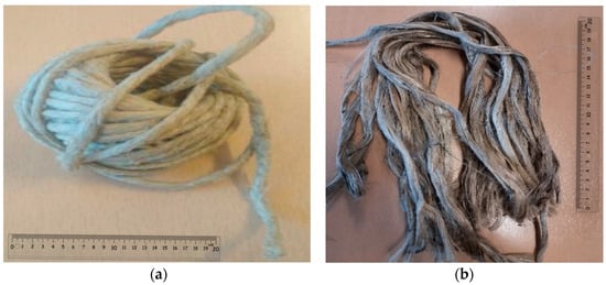
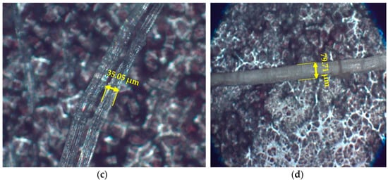
Figure 1.
Fibers used in the study along with their microstructure: Hemp fibers shown in (a,c), and Jute fibers in (b,d).

Table 1.
Mechanical characteristics and manufacturers of the materials utilized.
Table 2.
Mechanical and physical properties of jute and hemp fiber [32].
To ensure the resulting filament meets specific quality, performance, and application-related criteria, it is essential to determine the dimensions of small hemp pieces and the diameter of jute fibers before transforming them into filament form. Under 10 × 10 magnification, the microscope provided the following detailed measurements: the hemp fiber length was 35.05 μm, the width was 23.78 μm, and the jute fiber diameter measured 79.71 μm (see Figure 1c,d). Figure 2 presents a schematic roadmap that clarifies the distinction between the materials used, specifying which were purchased, which were employed in multi-material designs, and which were recycled, along with the tests performed on each group.
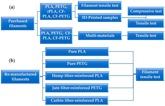
Figure 2.
Schematic roadmap illustrating the categorization of materials used in the study: (a) purchased materials and (b) re-manufactured materials.
2.2. Filament Fabrication
The objective was to create new filaments by re-manufacturing the original commercially produced filaments to evaluate their ultimate tensile strength (UTS) and compare these results with those of the initial filaments. The preparation process began with chopping the original filament into small particles utilizing a filament cutting machine. These particles were then fed into a single-screw extruder to produce new filaments.
In the Materials Science laboratory, a filament-cutting machine was utilized. A segment of the commercially produced filament was sliced into pieces and placed into the machine’s chamber. After securing the chamber to the apparatus, it was operated for seven seconds to generate the final particles (see Figure 3). Five materials—PLA, rPLA, CF–PLA, PETG, and CF–PETG—were cut separately and prepared for manufacturing new filaments. The filament was created using a filament maker machine after being ground with the WŻ-1 grinder machine. The PLA and PETG particles were fed into the machine’s barrel and heated to specific temperatures. The extrusion temperatures were set to 185 °C and 200 °C for PLA and PETG polymers, respectively. The extrusion speed was set to the maximum level on the machine to ensure material melting. Inside the barrel, the rotating screw advanced the molten material, simultaneously mixing and blending it to maintain uniform quality. After the material was fully melted and homogenized, it was extruded through a die to produce filaments with a specified diameter of 1.75 mm. The filament was then cooled with a fan and readied for subsequent testing.
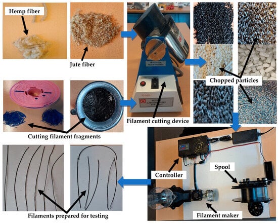
Figure 3.
Filament cutting procedure.
The same process was repeated while mixing hemp fiber with PLA and rPLA filaments and jute fiber with PETG filaments. The selection of hemp with PLA and jute with PETG was based on preliminary trials that demonstrated better interfacial bonding and mechanical performance with these specific material combinations. Additionally, extruding hemp and jute composites with 7 wt% was achieved without difficulty. The percentages of fibers were chosen based on prior research [33] and practical considerations of printability and mechanical properties. However, attempts to re-manufacture CF–PETG were unsuccessful. According to previous research [34], recycling carbon fiber-reinforced thermoset composites has been particularly challenging, and similar difficulties may apply to carbon fiber-reinforced PETG. When natural fibers were added to CF–PETG and CF–PLA, the extrusion process became problematic. Extruding hemp with CF–PLA or jute fiber with CF–PETG was not feasible.
Due to circumstances that were difficult to control, varying filament diameters were obtained, which differed from commercially manufactured filament. These conditions included the inability of the mixing chamber in the extrusion machine to provide a homogeneous blend of the molten material, leading to inconsistent filament uniformity. Additionally, difficulties in calibrating the melting temperature and extrusion speed resulted in diameter variations and noticeable disturbances in the amount of extruded filament. Moreover, the lack of control over cooling, represented by the presence of a single-speed fan, exacerbated issues during the manufacturing process. Despite these challenges and difficulties, the required and sufficient samples were obtained for testing. Experimental adjustments were made to the temperature settings to align with the extrusion speed, and the available cooling system was adjusted to produce testable samples. The total number of the re-manufactured filament tensile test is 35.
The filament diameter varied for each material. Table 3 shows the different diameters of the materials after they were re-manufactured and reinforced with natural fibers.
Table 3.
Diameters of the materials after re-manufacturing and reinforcing with natural fibers.
The reduced filament diameter observed was likely due to challenges in controlling the fan speed and the rapid transition from the molten to solid state during extrusion. Additionally, the speed of the extruder played a role in this deviation, impacting the cooling rate and resulting in thinner filaments than expected.
2.3. Specimen Manufacturing
The experimental non-reinforced materials included PLA, recycled PLA (rPLA), and PETG filaments having a diameter of 1.75 mm. Additionally, CF–PLA and CF–PETG original filaments were enhanced with fibers containing 10 wt.% carbon fibers, each having a length of 100 μm. Tensile test specimens were designed according to ISO 527-2 standards [35], and compressive specimens were manufactured following ASTM D695 [36]. The CAD model of the samples was created using Solidworks 2024 software and saved as an STL file. The 3D specimens were produced using Material Extrusion (MEX) technology on a Geetech A20M 3D printer (Shenzhen, China), with printing operations managed through Ultimaker Cura 5.2.1 software (see Figure 4). Samples were produced in a flat orientation, with five samples produced for each original material using identical print settings. Examples of these samples are shown in Figure 5. The printing parameters outlined in Table 4, including the melting and platform temperatures, were selected based on the manufacturer’s recommendations from the material data sheets. These parameters, such as temperatures, layer heights, and print speeds, were chosen to optimize adhesion, minimize warping, and ensure smooth surface finishes, consistent with best practices in the field. For instance, the nozzle temperatures were precisely matched to each filament’s melting point to guarantee a consistent material flow during extrusion, while the selected layer height offered a balance between mechanical integrity and printing efficiency. The total number of the 3D manufactured specimens for the tensile and compressive test is 50.
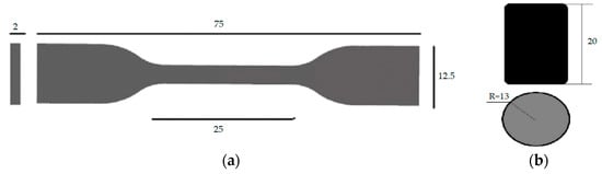
Figure 4.
Dimensions of samples designed using SolidWorks software: (a) tensile specimen, (b) compressive specimen.
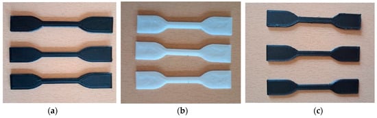
Figure 5.
Actual appearance of various additively manufactured tensile and compressive test specimens created with original filaments: (a) rPLA, (b) PLA, (c) PETG, (d) CF–PLA, and (e) CF–PETG. (f) Displays the compressive specimens for all materials.
Table 4.
Printing parameters for additively manufactured samples produced with the Geetech A20M 3D printer.
2.4. Multi-Material Design
In this investigation, four distinct types of polymeric filaments tailored for additive manufacturing were extruded. These categories included pure PLA and PETG polymers, as well as PLA and PETG polymeric composite filaments reinforced with 10 wt% carbon fiber. According to the material provider, the average length of the carbon fibers was 100 µm. The samples were created using a Bambu Lab P1S 3D printer (Austin, TX, USA), which is capable of additive manufacturing with up to four different materials in a layer-by-layer manner. In our experimentation, all four feedstock materials were used, with each material corresponding to a dedicated feeding system. The STL files of the samples were sliced into standard G-code for printing.
Tensile specimens of single-gradient composites, denoted as PLA/CF–PLA and PETG/CF–PETG, consisted of 50% PLA and 50% CF–PLA, and 50% PETG and 50% CF–PETG, as well as 50% PLA and 50% PETG. Additionally, the multi-gradient composites were created using the following two specific combinations: PLA/CF–PLA (PCFP) and PETG/CF–PETG (GCFG). The PLA/CF–PLA setup featured 25% PLA on the outer layers and 50% CF–PLA in the central core (PCFPP). For the PETG/CF–PETG combination, 25% PETG was used for the outer layers with 50% CF–PETG as the core (GCFGG). Another variant, the PETG/PLA composite, included 25% PETG on the outer layers and 50% PLA in the inner core (GPG). For comparison, additively manufactured samples of pure neat PLA, PETG, CF–PLA, and CF–PETG were also prepared, and their properties were assessed alongside various gradient composites. The selection of the multi-material design samples was based on optimizing material properties for specific structural applications. The choice was influenced by prior studies that demonstrated the benefits of combining materials with different mechanical characteristics to enhance overall performance [37,38]. Figure 6 displays the schematic of the functional grading sequences for various PLA, PETG, and CF–PLA–CF–PETG composite layers. The samples were created with different gradient stacking arrangements, including both single- and multi-gradient setups with varying percentages of stacking layers.
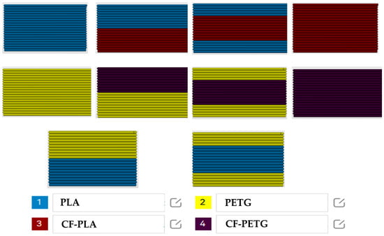
Figure 6.
Schematic of functional grading sequences for various multi-material tensile specimens, produced using Bambu Studio v1.8.4.51 software.
The material properties of PLA and PETG produced under the specified printing parameters are outlined in Table 5. This study delved into the tensile strengths of the specimens, determined by evaluating functionally specific volume ratios. For printing with PLA and CF–PLA, an optimal printing temperature of 210 °C was employed, while printing with PETG and CF–PETG required nozzle temperatures of 220 °C and 240 °C, respectively. Although Table 5 suggests an ideal bed temperature of 45 °C for PLA, a bed temperature of 70 °C was used for all prints involving PETG.
Table 5.
Printing settings employed while manufacturing multi-materials using Bambu 3D printer.
2.5. Experimentation
2.5.1. Filament Fixation
In this study, the tensile properties of the original filaments (not printed specimens and 3D specimens) and the re-manufactured filaments (not printed into a specimen), such as ultimate tensile strength and fracture strength, were determined at a crosshead speed of 5 mm/min, with a minimum of five repetitions for each test. Filaments of 300 mm in length were clamped using Bollard-style grips (see Figure 7). The Bollard part of the fixture had a diameter of 120 mm, consisting of two cylindrical grips mounted on a Zwick Roell Z100 tensile testing machine (Ulm, Germany). Testing was performed at a displacement rate of 5 mm/min, with a distance of 150 mm between the grips. One grip was secured in place, while the other was adjustable. The adjustable grip was attached to the load cell of the testing machine, which recorded the force exerted on the specimen.
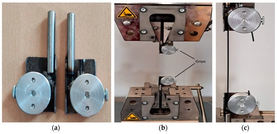
Figure 7.
Tensile testing of filaments: (a) Bollard grips used, (b) grip positioning within the test machine, and (c) close-up view of the grips.
2.5.2. Tensile and Compressive Testing of Additively Manufactured Specimens
The tensile and compressive characteristics of the various configurations adhered to ISO 527-2 and ASTM D695 standards, respectively. For the tensile testing trial, specimens were manufactured with dimensions of 110 mm in length, 20 mm in width, and 4 mm in thickness. The different graded multi-material compressive samples had a diameter of 13 mm and a length of 20 mm. Thirty samples were prepared for both tensile and compressive tests, with each material configuration undergoing three repetitions. The experiments were conducted using a Zwick/Roell Z100 testing machine equipped with a 10 kN force transducer at a loading rate of 1 mm/min. Tensile properties, including tensile strength and failure mode, were evaluated under specific conditions, maintaining a consistent grip-to-grip distance of 78 mm. Additionally, compressive properties, including E modulus and failure mode, were computed for the samples. Figure 8 shows one of the samples during tensile and compressive tests conducted on the 3D-manufactured specimens.
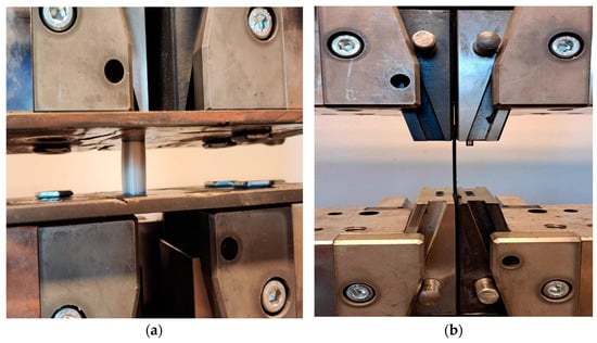
Figure 8.
Experimental setup for mechanical testing of additively manufactured samples: (a) compressive test setup for PLA sample and (b) tensile test setup for PETG sample.
2.5.3. Tensile Properties of Multi-Material Composites
Tensile specimens of the various multi-material configurations, including those with gradient additives, were fabricated according to ISO 527-2 standards. These specimens were designed with dimensions of 150 mm in length, 20 mm in width, and 4 mm in thickness. The tensile strength and modulus of the prepared samples were assessed using the Universal Testing Machine Zwick/Roell Z100, applying a tensile loading rate of 1 mm/min. Each set of additively manufactured multi-material samples underwent five repetitions of testing. A representation of the tensile test samples is illustrated in Figure 9.
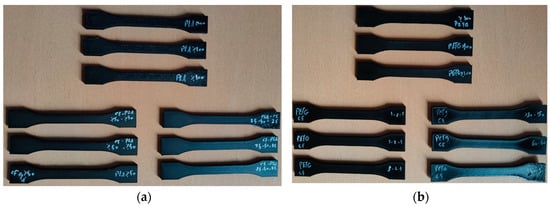
Figure 9.
Physical appearance of selected tensile specimens: (a) PLA and CF–PLA, and (b) PETG and CF–PETG.
3. Results and Discussion
3.1. Original Filament Tensile Test
Tensile testing was conducted on the original filament material, which had not undergone extrusion during the printing process. Figure 10 presents the stress–strain curves for the five different filament materials. The figure provides one representative result out of the three tests conducted for each material.
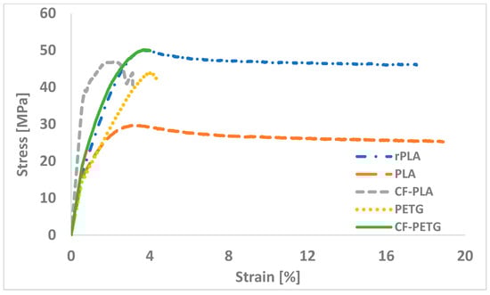
Figure 10.
Stress–strain curves for the original (non-printed) materials.
The CF–PETG filament exhibited a maximum stress of 50.14 MPa, closely matching the stress of rPLA filaments. The stress of CF–PETG was higher than that of rPLA, PLA, CF–PLA, and PETG by 0.2%, 70%, 6.7%, and 14.4%, respectively. The CF–PETG filament demonstrated consistent stress resistance throughout the specified strain range. In contrast, the other filaments experienced a reduction in stress resistance after reaching their respective peak stress levels. Compared to the tensile strength values provided by the manufacturer, the tensile strength of PLA, rPLA, PETG, and CF–PLA decreased by 30%, 20%, 28%, and 27%, respectively. This reduction can be attributed to several factors, including variations in environmental conditions (such as humidity and temperature), differences in testing equipment or setup (e.g., grip type, alignment, or loading speed), and the storage conditions of the filament prior to testing (see Table 1 for manufacturer data).
3.2. Additively Manufactured Specimen Tensile Testing
Figure 11 shows the stress–strain curves obtained from the tensile tests of different original materials. The results indicate that rPLA and CF–PLA samples had the highest and nearly highest maximum stresses of 50 MPa and 46.5 MPa, respectively. This result highlights the enhancement that carbon fiber incorporation can bring to PLA’s mechanical properties. Pure PLA exhibited a stress of 36 MPa, which was lower than that of rPLA and CF–PLA. This suggests that both recycling and reinforcement with carbon fibers can significantly enhance PLA’s tensile strength. The PETG showed commendable performance at 45 MPa, indicating its good inherent mechanical properties, although it was still inferior to rPLA and CF–PLA. Interestingly, CF–PETG recorded a stress of 31 MPa, lower than pure PETG. This result could be due to factors such as inadequate bonding between the PETG matrix and carbon fibers or an unfavorable ratio of reinforcement. The rPLA exhibited 38% higher stress than pure PLA, while CF–PLA demonstrated a 50% increase in tensile stress compared to CF–PETG. The dissimilarities in chemical and mechanical properties between PLA and PETG may contribute to these variations. The varying compatibility of the added carbon fibers with each pure material might be influencing the overall performance observed in the tensile tests. Figure 12 illustrates the main failure scenarios observed during tensile tests. The fracture sites differed depending on the loading points, with pure PLA showing superior performance. While failure within the gauge zone is preferred for accurate strain measurement, the mechanical behavior of the material is still reliably reflected in the sample that failed outside the gauge zone. The test was conducted under standard conditions, with uniform stress distribution observed prior to failure. Therefore, despite the location of the fracture, the results remain valid and provide valuable insights into the material’s performance.
Figure 11.
Stress–strain curves from tensile tests of additively manufactured specimens.
Figure 12.
Specimens after tensile tests: (a) rPLA, (b) PLA, (c) CF–PLA, (d) PETG, and (e) CF–PETG. The red circles indicate the areas of failure.
3.3. Additively Manufactured Specimen Compressive Test
This section presents the results of compression tests conducted on additively manufactured specimens fabricated using the original filament materials. As depicted in Figure 13, the compression behavior during the tests varied among the different materials examined. The stress–strain curves indicate that the highest maximum compressive stress of 81.7 MPa was recorded for rPLA. In contrast, the white PLA material exhibited the lowest stress at 42.8 MPa at a strain of 3.4%. The CF–PETG demonstrated a compressive stress of 48.6 MPa at a similar strain of 3.4%. Notably, CF–PLA specimens displayed a 61% higher compressive stress compared to CF–PETG. While pure PETG showed satisfactory mechanical properties, it was still inferior to CF–PLA. The compressive strength of PETG, measured at 53.7 MPa, aligns well with values reported in previous studies, which range from 41 to 98 MPa [39]. Both PETG and CF–PETG exhibited reduced compressive deformation, while rPLA exhibited the highest maximum deformation, consistent with the findings of Hsueh et al. [27]. Hsueh and colleagues concluded that, apart from thermal deformation, the mechanical properties of PLA surpassed those of PETG. In this study, adding 10 wt% carbon fiber to PETG decreased its compressive stress, which could be explained by factors such as the quality of dispersion and bonding with the PETG matrix. Numerous investigations have shown similar findings, highlighting the significance of fiber-matrix interactions in composite materials [27]. An optical microscope image of the compressed specimens is shown in Figure 14.
Figure 13.
Stress–strain curves for compressive test of additively manufactured specimen.
Figure 14.
The morphology of the compressed samples following the compressive test: (a) rPLA, (b) PLA, (c) CF–PLA, (d) PETG, and (e) CF–PETG.
3.4. Re-Manufactured Filament Tensile Test
Tensile tests were conducted on re-manufactured filaments, encompassing a set of the following five specimens: rPLA, PLA, CF–PLA, PETG, and hemp fiber-reinforced PLA/rPLA filaments. Additionally, jute fiber-reinforced PETG underwent re-manufacturing and testing in this segment. Notably, the re-manufactured PLA and rPLA exhibited superior tensile strength compared to the original filaments, which can be attributed to the consistent layer bonding in the PLA samples. However, the recycled CF–PLA showed a 4% reduction in strength compared to the original filaments. This decrease in tensile strength is likely due to the formation of fiber clusters during recycling, weakening the adhesive bond between the PETG and carbon matrix. The clusters reduce the mechanical properties of the composite by impairing interlayer adhesion. Regarding PETG filament, the recycled PETG exhibited lower strength than the original filaments. On the contrary, incorporating 7 wt% hemp fiber into PLA and rPLA filaments and re-manufacturing them resulted in filaments with superior tensile strength compared to the original ones. In the case of white PLA with hemp filaments, the tensile strength surpassed that of the original filaments and pure recycled PLA by 29% and 26%, respectively. Furthermore, adding 7 wt% hemp fiber to rPLA increased its tensile strength by 7% compared to the original rPLA filament, though it resulted in a 6% decrease in tensile strength compared to re-rPLA. Moreover, adding 7 wt% jute fiber to PETG enhanced the tensile strength by 12% and 15% for the original and re-manufactured PETG filaments, respectively. Figure 15 shows the sample after the test. Additionally, a comparison between the maximum applied load and ultimate tensile strength (UTS) for both the original and re-manufactured filaments is shown in Table 6.
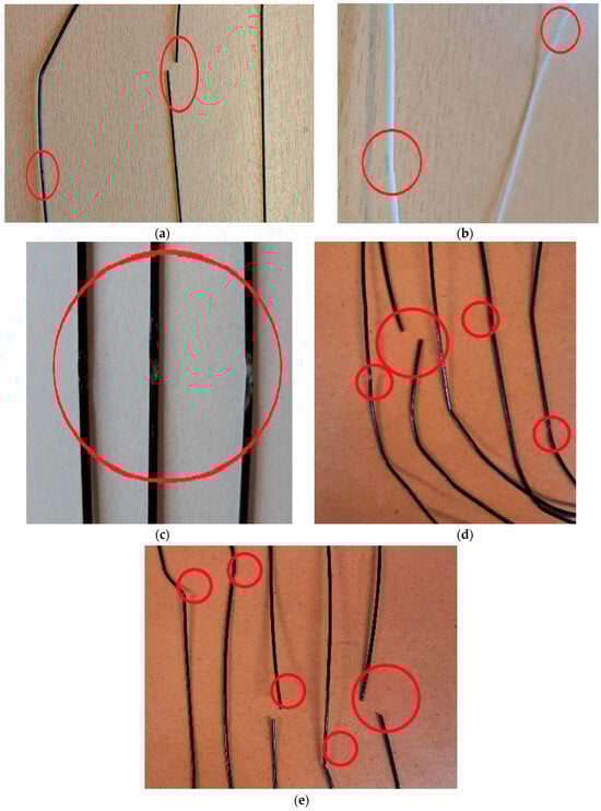
Figure 15.
Fractured surfaces of re-manufactured filament samples: (a) re-rPLA, (b) re-PLA, (c) re-PLA + Hemp fiber, (d) re-PETG, and (e) re-PETG + Jute fiber. The red circles indicate the areas of failure.
Table 6.
Maximum applied load and tensile strength, values for the original, re-manufactured, and reinforced filaments.
3.5. Tensile Features of Multi-Gradient and Single PLA, PETG, CF–PLA, and CF–PETG Composites
Figure 16 presents the tensile properties of neat (100% PLA (P), 100% PETG (G), 100% CF–PLA (CFP), 100% CF–PETG (CFG)), single (50% PLA + 50% CF–PLA (PCFP), 50% PETG + 50% CF–PETG (GCFG), 50% PLA + 50% PETG (PG)), and multi-graded (25% PLA + 50% CF–PLA + 25% PLA (PCFPP), 25% PETG + 50% CF–PETG + 25% PETG (GCFGG), 25% PETG + 50% PLA + 25% PETG (GPG)) materials. Specifically, Figure 16a shows the tensile force-elongation curves for the neat, single, and functionally graded composites. Figure 16b,c displays the Young’s modulus (E modulus) and tensile strength of different graded composites for the PLA, CF–PLA, PETG, and CF–PETG materials. In addition, Table 7 provides a detailed comparison of the tensile properties of the examined specimen materials. The results indicate that the tensile strengths of the neat materials are quite similar, with neat PLA exhibiting a slightly higher tensile strength than PETG by 0.03%. Generally, PLA is recognized for its higher tensile strength compared to PETG, making it a more rigid material with lower elongation at break. Conversely, PETG demonstrates higher elongation at break, making it more flexible, impact-resistant, and less brittle than PLA. For specimens composed of 100% layers, the tensile strength of CF–PLA was 0.04% higher than that of neat PLA. In contrast, the tensile strength of CF–PLA decreased by 65% compared to neat PETG. This reduction could be attributed to the introduction of carbon fibers, which potentially increases the occurrence of microvoids within the printed layers, thereby diminishing the overall tensile strength of the composite.
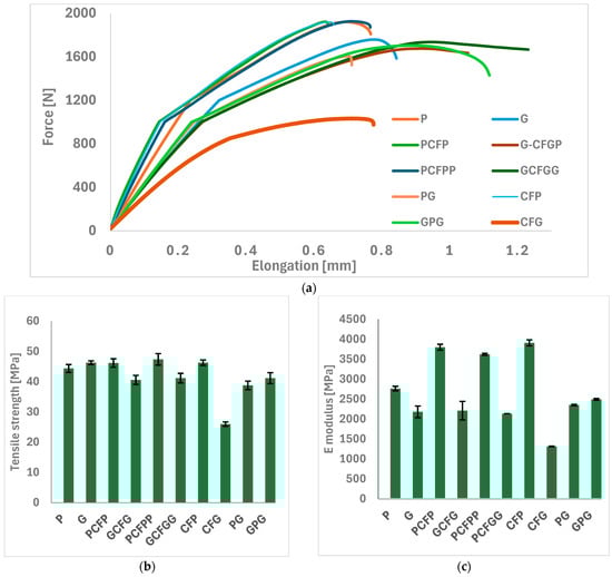
Figure 16.
Tensile testing results: (a) Load-elongation curves, (b) tensile strength values, and (c) E-modulus measurements.
Table 7.
Mechanical qualities of the single, multi-graded, and neat materials.
To compare the tensile strength of various additively manufactured specimens, the highest tensile strength, 47.4 MPa, was achieved by specimens composed of PCFPP. This result was close to the specimens manufactured by PCFP, which showed a tensile strength of 46.2 MPa. Specimens manufactured with multi-layers of CFPLA and PLA composite showed improved tensile strength, with a 4% increase for PCFP and 7% for PCFPP compared to neat PLA. Conversely, specimens manufactured with multi-material layers of PETG and CF–PETG experienced a reduction in tensile strength compared to neat PETG. The tensile strength decreased by 4% for GCFGG and by 5% for GCFG. These results demonstrate the distinct impacts of material compositions on tensile strength, showcasing the advantages of CFPLA in enhancing tensile properties while also highlighting the challenges of integrating carbon fiber with PETG.
For the composite specimens of PLA and PETG, the highest tensile strength was observed in the GPG specimens, reaching 41.19 MPa. This value is lower than the tensile strength of specimens manufactured with 100% layers of neat PLA and neat PETG. The results suggest that while there are certain benefits to using a layered composite of PLA and PETG, the tensile strength of such composites does not always surpass that of using either material alone. This observation underscores the importance of optimizing the adhesion and intermolecular forces between different materials in composites to fully leverage their individual advantages. By enhancing the bonding quality between PLA and PETG, it is possible to create composites that better utilize the unique strengths of each material.
For the tensile modulus, specimens manufactured with 100% CF–PLA layers exhibited the highest tensile modulus at 3914 MPa. Among the single and multi-graded PLA + CFPLA multi-material composites, the specimens composed of 50% PLA + 50% CF–PLA showed a relatively high tensile modulus of 3805 MPa, outperforming other multi-layered composites. Conversely, the lowest tensile modulus was observed in the specimens manufactured with 100% CF–PETG, with a value of 1318 MPa. Furthermore, the multi-layered composites of PLA and PETG displayed reduced mechanical properties, which can be attributed to inadequate interfacial bonding between the two polymers. This poor adhesion likely stems from the differences in optimal printing temperatures and material characteristics of PLA and PETG, which hinder the formation of a strong, cohesive bond during the AM process.
Optical microscope images of the fractured surfaces of the neat, single, and multi-graded composite material specimens are presented in Figure 17. The fractured surfaces of PLA appeared brittle, as indicated by the clear and sharp fracture edges. The fracture process exhibited deformation and elongation of the PETG, highlighting an increase in toughness (Figure 17d). Moreover, the fracture of the PLA matrix within the CFPLA layers exhibited brittleness, and clear gaps between the PLA substrate and the carbon fibers suggested an inadequate bonding interface (Figure 17d). In CF–PETG, noticeable structural changes around the fibers can be observed, demonstrating how the stiffness of PETG interacts with the gritty texture of the carbon fibers (Figure 17h). The composite specimens manufactured by PLA mixed with PETG exhibited a clear, sharp boundary between the different parts. This difference in behavior between the materials can create some pressure, possibly causing the layers to separate (see Figure 17j).
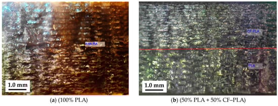
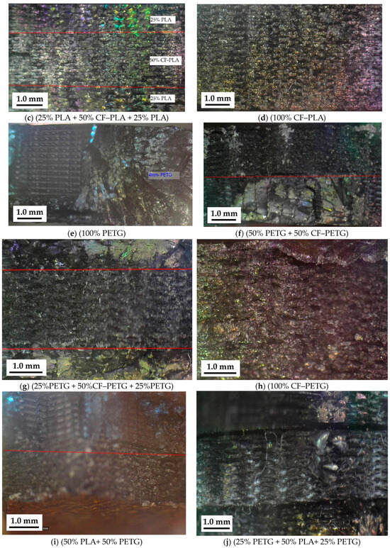
Figure 17.
Microscopy images of fractured zones in test specimens: (a) P, (b) PCFP, (c) PCFPP, (d) CFP, (e) G, (f) GCFG, (g) GCFGG, (h) CFG, (i) PG, and (j) GPG. The red lines show the border between the two materials in the case of composites of various materials.
The findings of this study have broader implications beyond the specific re-manufactured filaments tested. The results demonstrate that recycled and natural fiber-reinforced filaments can achieve mechanical properties comparable to or even better than original, commercially available filaments, offering sustainable and high-performance alternatives for industrial applications. Furthermore, the reinforcement techniques and multi-material composite designs explored in this research can be applied to other polymer-based materials, providing valuable insights for the additive manufacturing and materials science communities. These findings encourage further exploration into sustainable materials for real-world applications in industries like automotive, aerospace, and construction.
4. Conclusions
This research provides a thorough evaluation of the mechanical properties of various filaments and their additively manufactured equivalents, emphasizing the impact of material composition, reinforcement strategies, and processing techniques. Comprehensive tensile and compression testing revealed critical findings on the mechanical behavior of the specimens. The key conclusions of this study are summarized as follows:
- Among the tested original filaments, CF–PETG achieved the highest maximum stress at 50.14 MPa, outperforming rPLA, PLA, CF–PLA, and PETG.
- Re-manufactured filaments showed mixed results. Both CF–PLA and recycled PLA (rPLA) exhibited improved tensile strengths over their original versions, with rPLA’s strength increasing by 29% with hemp fiber reinforcement. Recycled CF–PLA experienced a slight 4% reduction in strength compared to the original. Re-manufactured PETG displayed lower tensile strength than original PETG, but the addition of jute fiber increased the strength of both recycled and original PETG by 15% and 12%, respectively.
- The highest tensile strengths were found in additively manufactured specimens made from rPLA and CF–PLA, with values of 50 MPa and 46.5 MPa, respectively, indicating the reinforcing effect of carbon fiber. The PETG and pure PLA also performed well, although CF–PETG showed lower tensile strength (31 MPa), likely due to insufficient fiber-matrix bonding.
- The rPLA exhibited the highest compressive stress at 81.7 MPa, demonstrating strong resistance to compressive loads. The CF–PLA showed a 61% higher compressive stress compared to CF–PETG, while both PETG and CF–PETG displayed lower resistance to compressive deformation.
- Specimens made entirely of CF–PLA showed a tensile modulus of 3914 MPa, while a 50% PLA + 50% CF–PLA multi-material composite demonstrated effective reinforcement with a tensile modulus of 3805 MPa. However, 100% CF–PETG had the lowest tensile modulus at 1318 MPa, pointing to potential fiber-matrix interaction issues.
- Multi-layered PLA and PETG composites showed reduced mechanical performance, largely due to sharp interfaces between the materials causing stress at the transition points, which can lead to delamination. Ensuring strong adhesion between materials in multi-layered composites is essential to avoid this issue.
Author Contributions
Conceptualization, R.F.F. and Z.S.; methodology, R.F.F., Y.I. and M.N.B.; validation, R.F.F., Y.I. and M.N.B.; formal analysis, M.M.H. and N.D.S.; investigation, R.F.F. and M.M.H.; resources, Z.S. and I.O.; data curation, T.S.G. and N.D.S.; writing—original draft preparation, R.F.F.; writing—review and editing, R.F.F., M.M.H. and I.O.; visualization, R.F.F. and M.M.H.; supervision, Z.S. and I.O.; project administration, R.F.F.; funding acquisition, T.S.G. All authors have read and agreed to the published version of the manuscript.
Funding
This research received no external funding.
Data Availability Statement
The data supporting the reported results are available from the corresponding author upon reasonable request.
Conflicts of Interest
The authors declare no conflicts of interest.
Abbreviations
| AM | Additive Manufacturing |
| MEX | Material Extrusion |
| PLA | Polylactic Acid |
| PETG | Polyethylene Terephthalate Glycol |
| CF | Carbon Fiber |
| rPLA | Recycled Polylactic Acid |
| CF-PLA | Carbon Fiber-Reinforced Polylactic Acid |
| CF-PETG | Carbon Fiber-Reinforced Polyethylene Terephthalate Glycol |
| re-PLA + Hemp | Re-manufactured PLA with adding 7 wt% hemp fiber |
| re-rPLA + hemp | Re- manufactured rPLA with adding 7 wt% hemp fiber |
| re-PETG + Jute | Re-manufactured PETG with adding 7 wt% jute fiber |
| P | 100% PLA |
| G | 100% PETG |
| PCFP | 50% PLA + 50% CF-PLA |
| GCFG | 50% PETG + 50% CF-PETG |
| PCFPP | 25% PLA + 50% CF-PLA + 25% PLA |
| GCFGG | 25% PETG + 50% CF-PETG + 25% PETG |
| CFP | 100% CF-PLA |
| CFG | 100% CF-PETG |
| PG | 50% PLA+ 50% PETG |
| GPG | 25% PETG + 50% PLA+ 25% PETG |
References
- Pajonk, A.; Prieto, A.; Blum, U.; Knaack, U. Multi-Material Additive Manufacturing in Architecture and Construction: A Review. J. Build. Eng. 2022, 45, 103603. [Google Scholar] [CrossRef]
- Rudnik, M.; Hanon, M.M.; Szot, W.; Beck, K.; Gogolewski, D.; Zmarzły, P.; Kozior, T. Tribological Properties of Medical Material (MED610) Used in 3D Printing PJM Technology. Teh. Vjesn. 2022, 29, 1100–1108. [Google Scholar] [CrossRef]
- Dizon, J.R.C.; Espera, A.H.; Chen, Q.; Advincula, R.C. Mechanical Characterization of 3D-Printed Polymers. Addit. Manuf. 2018, 20, 44–67. [Google Scholar] [CrossRef]
- Hanon, M.M.; Zsidai, L. Sliding Surface Structure Comparison of 3D Printed Polymers Using FDM and DLP Technologies. IOP Conf. Ser. Mater. Sci. Eng. 2020, 749, 012015. [Google Scholar] [CrossRef]
- Popescu, D.; Zapciu, A.; Amza, C.; Baciu, F.; Marinescu, R. FDM Process Parameters Influence over the Mechanical Properties of Polymer Specimens: A Review. Polym. Test. 2018, 69, 157–166. [Google Scholar] [CrossRef]
- Dobos, J.; Hanon, M.M.; Oldal, I. Effect of Infill Density and Pattern on the Specific Load Capacity of FDM 3D-Printed PLA Multi-Layer Sandwich. J. Polym. Eng. 2022, 42, 118–128. [Google Scholar] [CrossRef]
- Rasheed, R.K.; Mansoor, N.S.; Mohammed, N.H.; Qasim, S.S.B. Subtractive and Additive Technologies in Fixed Dental Restoration: A Systematic Review. J. Tech. 2023, 5, 162–167. [Google Scholar] [CrossRef]
- Fonseca, J.; Ferreira, I.A.; de Moura, M.F.S.F.; Machado, M.; Alves, J.L. Study of the Interlaminar Fracture under Mode I Loading on FFF Printed Parts. Compos. Struct. 2019, 214, 316–324. [Google Scholar] [CrossRef]
- Taylor, G.; Anandan, S.; Murphy, D.; Leu, M.; Chandrashekhara, K. Fracture Toughness of Additively Manufactured ULTEM 1010. Virtual Phys. Prototyp. 2019, 14, 277–283. [Google Scholar] [CrossRef]
- Rashid, F.L.; Hashim, A.; Dulaimi, A.; Hadi, A.; Ibrahim, H.; Al-Obaidi, M.A.; Ameen, A. Enhancement of Polyacrylic Acid/Silicon Carbide Nanocomposites’ Optical Properties for Potential Application in Renewable Energy. J. Compos. Sci. 2024, 8, 123. [Google Scholar] [CrossRef]
- Sweeney, C.B.; Lackey, B.A.; Pospisil, M.J.; Achee, T.C.; Hicks, V.K.; Moran, A.G.; Teipel, B.R.; Saed, M.A.; Green, M.J. Welding of 3D-Printed Carbon Nanotube–Polymer Composites by Locally Induced Microwave Heating. Sci. Adv. 2017, 3, e1700262. [Google Scholar] [CrossRef] [PubMed]
- Fatima Faidallah, R.; Hanon, M.M.; Szakál, Z.; Oldal, I. Study of the Mechanical Characteristics of Sandwich Structures FDM 3D-Printed. Acta Polytech. Hung. 2023, 20, 7–26. [Google Scholar] [CrossRef]
- Delgado, G.F.; Pinho, A.C.; Piedade, A.P. 3D Printing for Cartilage Replacement: A Preliminary Study to Explore New Polymers. Polymers 2022, 14, 1044. [Google Scholar] [CrossRef] [PubMed]
- Ansari, M.Q.; Redmann, A.; Osswald, T.A.; Bortner, M.J.; Baird, D.G. Application of Thermotropic Liquid Crystalline Polymer Reinforced Acrylonitrile Butadiene Styrene in Fused Filament Fabrication. Addit. Manuf. 2019, 29, 100813. [Google Scholar] [CrossRef]
- Ferreira, I.; Vale, D.; Machado, M.; Lino, J. Additive Manufacturing of Polyethylene Terephthalate Glycol /Carbon Fiber Composites: An Experimental Study from Filament to Printed Parts. Proc. Inst. Mech. Eng. Part L J. Mater. Des. Appl. 2019, 233, 1866–1878. [Google Scholar] [CrossRef]
- Santo, J.; Penumakala, P.K.; Adusumalli, R.B. Mechanical and Electrical Properties of Three-Dimensional Printed Polylactic Acid–Graphene–Carbon Nanofiber Composites. Polym. Compos. 2021, 42, 3231–3242. [Google Scholar] [CrossRef]
- Vidakis, N.; Petousis, M.; Grammatikos, S.; Papadakis, V.; Korlos, A.; Mountakis, N. High Performance Polycarbonate Nanocomposites Mechanically Boosted with Titanium Carbide in Material Extrusion Additive Manufacturing. Nanomaterials 2022, 12, 1068. [Google Scholar] [CrossRef]
- Cole, R.G.; Fayazbakhsh, K.; Avalos, A.; Nadeau, N.A. Improved Test Methods for Polymer Additive Manufacturing Interlayer Weld Strength and Filament Mechanical Properties. ASTM Spec. Tech. Publ. STP 2022, 1637, 325–338. [Google Scholar] [CrossRef]
- Rahimizadeh, A.; Kalman, J.; Fayazbakhsh, K.; Lessard, L. Recycling of Fiberglass Wind Turbine Blades into Reinforced Filaments for Use in Additive Manufacturing. Compos. Part B Eng. 2019, 175, 107101. [Google Scholar] [CrossRef]
- Liu, W.; Huang, H.; Zhu, L.; Liu, Z. Integrating Carbon Fiber Reclamation and Additive Manufacturing for Recycling CFRP Waste. Compos. Part B Eng. 2021, 215, 108808. [Google Scholar] [CrossRef]
- Pierson, H.A.; Celik, E.; Abbott, A.; De Jarnette, H.; Sierra Gutierrez, L.; Johnson, K.; Koerner, H.; Baur, J.W. Mechanical Properties of Printed Epoxy-Carbon Fiber Composites. Exp. Mech. 2019, 59, 843–857. [Google Scholar] [CrossRef]
- Ferreira, R.T.L.; Amatte, I.C.; Dutra, T.A.; Bürger, D. Experimental Characterization and Micrography of 3D Printed PLA and PLA Reinforced with Short Carbon Fibers. Compos. Part B Eng. 2017, 124, 88–100. [Google Scholar] [CrossRef]
- Hanon, M.M.; Marczis, R.; Zsidai, L. Anisotropy Evaluation of Different Raster Directions, Spatial Orientations, and Fill Percentage of 3D Printed PETG Tensile Test Specimens. Key Eng. Mater. 2019, 821, 167–173. [Google Scholar] [CrossRef]
- Kichloo, A.F.; Raina, A.; Haq, M.I.U.; Wani, M.S. Impact of Carbon Fiber Reinforcement on Mechanical and Tribological Behavior of 3D-Printed Polyethylene Terephthalate Glycol Polymer Composites—An Experimental Investigation. J. Mater. Eng. Perform. 2022, 31, 1021–1038. [Google Scholar] [CrossRef]
- Singh, A.K.; Saltonstall, B.; Patil, B.; Hoffmann, N.; Doddamani, M.; Gupta, N. Additive Manufacturing of Syntactic Foams: Part 2: Specimen Printing and Mechanical Property Characterization. JOM 2018, 70, 310–314. [Google Scholar] [CrossRef]
- Mansour, M.; Tsongas, K.; Tzetzis, D.; Antoniadis, A. Mechanical and Dynamic Behavior of Fused Filament Fabrication 3D Printed Polyethylene Terephthalate Glycol Reinforced with Carbon Fibers. Polym.-Plast. Technol. Eng. 2018, 57, 1715–1725. [Google Scholar] [CrossRef]
- Hsueh, M.-H.; Lai, C.-J.; Wang, S.-H.; Zeng, Y.-S.; Hsieh, C.-H.; Pan, C.-Y.; Huang, W.-C. Effect of Printing Parameters on the Thermal and Mechanical Properties of 3D-Printed PLA and PETG, Using Fused Deposition Modeling. Polymers 2021, 13, 1758. [Google Scholar] [CrossRef] [PubMed]
- Niu, C.; Luan, C.; Shen, H.; Song, X.; Fu, J.; Zhang, L.; Sun, Y.; Xu, G.; Ruan, Z. Tunable Soft–Stiff Hybridized Fiber-Reinforced Thermoplastic Composites Using Controllable Multimaterial Additive Manufacturing Technology. Addit. Manuf. 2022, 55, 102836. [Google Scholar] [CrossRef]
- Faidallah, R.F.; Hanon, M.M.; Vashist, V.; Habib, A.; Szakál, Z.; Oldal, I. Effect of Different Standard Geometry Shapes on the Tensile Properties of 3D-Printed Polymer. Polymers 2023, 15, 3029. [Google Scholar] [CrossRef] [PubMed]
- Salcedo, E.; Baek, D.; Berndt, A.; Ryu, J.E. Simulation and Validation of Three Dimension Functionally Graded Materials by Material Jetting. Addit. Manuf. 2018, 22, 351–359. [Google Scholar] [CrossRef]
- Baca, D.; Ahmad, R. The Impact on the Mechanical Properties of Multi-Material Polymers Fabricated with a Single Mixing Nozzle and Multi-Nozzle Systems via Fused Deposition Modeling. Int. J. Adv. Manuf. Technol. 2020, 106, 4509–4520. [Google Scholar] [CrossRef]
- Manaia, J.P.; Manaia, A.T.; Rodriges, L. Industrial Hemp Fibers: An Overview. Fibers 2019, 7, 106. [Google Scholar] [CrossRef]
- Gupta, A.; Hasanov, S.; Fidan, I. Processing and Characterization of 3D-Printed Polymer Matrix Composites Reinforced with Discontinuous Fibers. In Proceedings of the 2019 International Solid Freeform Fabrication Symposium, Austin, TX, USA, 12–14 August 2019. [Google Scholar]
- Zhang, J.; Chevali, V.S.; Wang, H.; Wang, C.H. Current Status of Carbon Fibre and Carbon Fibre Composites Recycling. Compos. Part B Eng. 2020, 193, 108053. [Google Scholar] [CrossRef]
- ISO 527-2:2012; Plastics—Determination of Tensile Properties—Part 2: Test Conditions for Moulding and Extrusion Plastics. European Committee for Standardisation: Brussels, Belgium, 2012.
- ASTM D695-23; Standard Test Method for Compressive Properties of Rigid Plastics. American Society for Testing and Materials: West Conshohocken, PA, USA, 2023. [CrossRef]
- Palaniyappan, S.; Annamalai, G.; kumar Sivakumar, N.; Muthu, P. Development of Functional Gradient Multi-Material Composites Using Poly Lactic Acid and Walnut Shell Reinforced Poly Lactic Acid Filaments by Fused Filament Fabrication Technology. J. Build. Eng. 2023, 65, 105746. [Google Scholar] [CrossRef]
- Yermurat, B.; Seçgin, Ö.; Taşdemir, V. Multi-Material Additive Manufacturing: Investigation of the Combined Use of ABS and PLA in the Same Structure. Mater. Test. 2023, 65, 1119–1126. [Google Scholar] [CrossRef]
- Amza, C.G.; Zapciu, A.; Constantin, G.; Baciu, F.; Vasile, M.I. Enhancing Mechanical Properties of Polymer 3D Printed Parts. Polymers 2021, 13, 562. [Google Scholar] [CrossRef]
Disclaimer/Publisher’s Note: The statements, opinions and data contained in all publications are solely those of the individual author(s) and contributor(s) and not of MDPI and/or the editor(s). MDPI and/or the editor(s) disclaim responsibility for any injury to people or property resulting from any ideas, methods, instructions or products referred to in the content. |
© 2024 by the authors. Licensee MDPI, Basel, Switzerland. This article is an open access article distributed under the terms and conditions of the Creative Commons Attribution (CC BY) license (https://creativecommons.org/licenses/by/4.0/).