1. Introduction
The parts of hydraulic systems are connected to each other by hydraulic lines, which can be formed from hydraulic hoses. There are advantages and disadvantages to using hydraulic hoses as hydraulic lines. The main advantage is the relative movement of the connected parts with respect to each other, Another advantage can be the reduction in pressure peaks during hydraulic shock due to the hydraulic capacity of the hydraulic hoses [
1,
2]. However, the mentioned influence of the hydraulic capacity of the hose also has the opposite effect; that is, the decrease in the hydraulic system’s stiffness. Wang described the problem of double-acting cylinder position control, where the hydraulic hose influences the system dynamics. Wang compared the PID controller with the ADRC (Active Disturbance Rejection Control), where the ADCR variant of the controller performs better and can compensate for the influence of the hydraulic hoses [
3]. Previously, the influence of different parameters on the performance of hoses has been investigated [
4]. The hydraulic capacity, bulk modulus [
5,
6] and viscoelastic properties [
7,
8] of hydraulic hoses are also related to the design.
A hydraulic hose consists of a rubber inner tube to ensure tightness. The next design component is the braid or spiral, which determines the maximum pressure loading. Hydraulic hoses are available with one or more braids (spirals) depending on the working pressure [
9]. With more braids (spirals), the flexibility of the hose is reduced. The working pressure of these hoses is up to 400 bar in common high-pressure hydraulic applications. A hydraulic hose must be able to withstand the maximum working pressure and must not be damaged even by short-term overloading. For this reason, pressure tests of hydraulic hoses are carried out [
10]. For high-pressure hydraulic hoses, the braid or spiral is made from steel wire [
11,
12]. For some applications, the hose braid or spiral can be made from aramid fiber or polyvinyl acetate [
13,
14]. When a hydraulic hose is loaded with fluid pressure, stresses are generated and transferred through the braid to the hose ends. Tensile forces are applied to the hose fitting if the hose is not installed correctly. This can result in damage to the hose and failure of the entire hydraulic system. Therefore, the importance of the right hose mounting is paramount.
The angle of the hydraulic hose braid has a major influence on the hydraulic hose deformation and the forces acting on the hose ends [
15,
16,
17,
18]. When the hose is loaded by fluid pressure, the hose steel braid tends to deform so that the opposing strands of the braid are at a neutral braid angle to each other at which the axial and hoop stress components are in balance. This deformation causes relative friction between the steel braid and the rubber tube or rubber interlayer of the hose. The degree of deformation of a hydraulic hose influences its service life [
19]. The solution to this problem is the method of braiding the steel wires at a neutral braid angle φ
N = 54.7356° to the hose axis. In this case, the balance between axial and hoop stresses is ensured. When manufacturing hydraulic hoses, the aim is to maintain the required braid angle. This is ensured by the right combination of the braiding rate and feed rate of the manufacturing machine [
20].
The aim of this work is to determine the influence of the braid angle on the deformation of the hydraulic hose and the forces acting on the hose ends. Within the framework of this research, an experimental device was created in order to test hydraulic hoses. The result is the determination of the dependence of the change in hose length and tensile force on the braid angle for hydraulic hoses with different internal diameters and different braid designs. This work serves as a summary of the measured data, which can be used for further research in the field of mathematical 3D modelling, for example in the field of finite element analysis of the deformation stress of hydraulic hoses.
2. Theoretical Background
The definition of the neutral braid angle, at which balance is reached between the stresses generated, is based on the theory of a closed cylinder of radius
r and wall thickness
s. The working pressure
p of the fluid acting on the hose inner wall generates hoop stress σ
O and axial stress σ
A (see
Figure 1) in the hose wall [
21].
The axial force
FA acting on the closed end of the hose is given below [
21]:
where
p is the fluid pressure and
r is the inner radius of the hose.
The axial stress σ
A generated in the wall of the hydraulic hose is given by the axial force
FA acting in the cross-sectional area of the hydraulic hose under the condition that
r >>
s [
21]:
where
s is the wall thickness of the hose.
We obtain the expression for axial stress σ
A by modifying Equations (1) and (2), as given below [
21]:
The hoop force
FO acting on the unit length of the hydraulic hose as given below [
21]:
where 1 is the unit length.
The hoop stress σ
O expressed per the unit length of the hydraulic hose is defined by Equation (5) [
21]:
We obtain the expression for hoop stress σ
O by modifying Equations (4) and (5), as given below [
21]:
Comparing Equations (3) and (6), it can be seen that the axial stress σ
A is half of the hoop stress σ
O.
Figure 2 shows a section of hydraulic hose where the wire tensions acting on the braid wires are indicated. A braid angle φ is given for the braid wire and the longitudinal axis of the hydraulic hose, as shown in
Figure 2 on the left and right [
21].
When an element of unit length is released, the height of the element is equal to
tanφ (see
Figure 2). For the balance between the hoop and axial stresses when the hose is subject to internal fluid pressure, Equation (7) for the hoop tension
TO and Equation (8) for the axial tension
TA must satisfy:
where 1∙
s is the area of the unit length element on which the hoop tension
TO acts and
tanφ∙
s is the area of the unit length element on which the axial tension
TA acts.
The neutral braid angle φ
N can be defined using the trigonometric [
21]:
Substituting Equations (7) and (8) into Equation (9), the expression is as follows [
21]:
We obtain the expression for the neutral braid angle by modifying Equation (10) [
21]:
Table 1 shows the changes in the geometry of the hydraulic hose caused by an internal fluid pressure increase. When the initial braid angle
φ becomes greater than the neutral braid angle
φN, the length of the hydraulic hose increases, and the hose diameter decreases. When the initial braid angle φ is less than the neutral braid angle
φN, the length of the hydraulic hose decreases, and the hose diameter increases. In both cases, the volume of the hose increases as the internal fluid pressure increases. With a neutral braid angle, there is no change in geometry due to the change in braid angle [
22].
The change in the braid angle due to the internal fluid pressure increase in the hose causes the axial force to be applied on the hose ends. In the case of hose shortening, a tensile force FT should be generated which acts on the hose fitting. In the case of hose extension, on the other hand, a pushing force FTH should be generated.
Manufacturers of high-pressure hydraulic hoses perform many tests on their products, which may include pressure or temperature tests or chemical resistance tests. One of the tests that are performed on high-pressure hoses is a test where the shortening or elongation of the hose is measured [
23]. This test is also part of the SAE J343 standard, which specifies the procedures for performing tests on high-pressure hydraulic hoses. This standard gives detailed instructions for performing the test and specifies allowable values for hose elongation or shortening depending on the hose design and size.
The percentage of hydraulic hose elongation or shortening may vary depending on the standard and the hose. For example, Fitch stated limits that allow a hose to be shortened by 6% of the original length and elongated by 2% of the original length in his publication [
23]. The testing of high-pressure hoses for possible elongation or shortening under working pressure is a common practice carried out by manufacturers, but these data are not widely available. The added value in this research will be the simultaneous sensing of the braid angle due to the removal of the rubber cover and the subsequent determination of its effect on hose shortening or elongation.
3. Experiment
For this study, experimental equipment was constructed in order to test hydraulic hoses with different inner diameters and design types (see
Figure 3). The left part of the figure shows the equipment design. The middle part of the figure shows the experimental equipment photo, and the right side shows a detail of the hose under test. To measure the braid angle under the fluid pressure, the hydraulic hose cover was removed from the hydraulic hose. The hydraulic hose cover did not affect the pressure capability, but only protected the hose from external influences. In this way, the angle of the hose outer braid could be measured visually. With two and more layers of braids, only the angle of the outer braid could be visually read without damaging the hose. For this reason, only hydraulic hoses with one braid were evaluated.
Figure 4 shows on the left side the tested hydraulic hoses.
Figure 4 shows on the right side a detail of the hose braid.
Table 2 shows the technical data and geometric dimensions of the tested hydraulic hoses. The table shows two types of braid for the tested hoses, namely SC and SN. Both types of hose braids are suitable for high pressure hydraulics. However, the SC designation defines the possibility of a tighter bend radius for these hoses, which is suitable for installations where space is at a minimum.
Figure 5 shows a simplified scheme of the experimental equipment. The source of the pressurized fluid was a hydraulic power unit which supplies fluid to the channel P. The hydraulic hose H was connected to the pressure line via a ball valve BV. The ball valve was only used to close the pressure line when changing the tested hose H. The top end of the hydraulic hose H was screwed to a top steel plate, which was connected to the aluminum frame. The required pressure value
p was set by the pressure proportional relief valve PRV. Working fluid passed through PRV to channel T. The fluid pressure value
p was measured by the pressure sensor PS. To measure the tensile force
FT of the hose in the longitudinal axis, the bottom end of the hose was attached to the force sensor FS. This tensile force
FT of the hose increased with increasing the working pressure
p. The force sensor FS was attached to a bottom steel plate, which was fixed into the frame structure. To measure the change in length of the hose, the bottom end of the hose was connected to a bracket which was fitted in the linear guides on the sides. This variant allowed one degree of freedom in the longitudinal axis of the hydraulic hose H. As the working pressure
p increased, the change in the hydraulic hose length Δ
l occurred. The length change Δ
l of the hose was determined by the laser distance sensor LS1. Simultaneously, the diameter
d of the hydraulic hose braid was measured by the optical micrometer LS2. A photo of the hose braid with the removed cover was taken with the camera CAM. The photos of the braids were taken in the working pressure range
p = (0 ÷ 140) bar. The pressure sensor PS and the force sensor FS were connected to measurement instrument, MS5070, from Hydrotechnik. The working fluid was mineral oil. The used parts are listed in
Table 3.
4. Results and Discussion
The static properties of nine hydraulic hoses were measured and evaluated. For comparison, hydraulic hoses with one steel braid and different inner diameters (din = 13, 16 and 19 mm) were selected. Two experiments were performed for each hydraulic hose. In the first experiment, the dependence hose length strain εl with respect to the working pressure p was determined. In this experiment, the top end of the hose under test was tightly threaded to the frame and the bottom end of the hose was attached to a linear guide that allowed movement in the longitudinal axis of the hose. In this experiment, the working fluid pressure p acting on the inner wall of the hydraulic hose caused the hose length to shorten. In the second experiment, the dependence of the hose tensile force FT with respect to the working pressure p was determined. The fitting of the bottom end of the hose was performed through the force sensor FS into the bottom fitted steel plate, which was rigidly connected to the frame of the equipment. In this case, there was no shortening of the hydraulic hose as in the first experiment. The working pressure p caused an increase in the tensile force FT, which was transferred by the braid steel wires to the hydraulic hose ends.
In both experiments, the braid angle of the tested hydraulic hose was simultaneously evaluated for working pressure
pmin = 0 bar a
pmax = 140 bar.
Figure 6 shows the method for the evaluation of the hydraulic hose braid angle. The evaluation of the braid angle was performed using Photron FASTCAM Viewer 4 (PFV4) software. Due to the optical distortion of the angle, the braid wires that crossed relative to each other in the center of the hydraulic hose were evaluated. This was the point where the least optical distortion occurred, which is due to the curvature of the hydraulic hose. Subsequently, the angle α
i was evaluated by using the function “angle 2” with two plotted lines parallel to the braid of the hose. Subsequently, the angle of the braid
φi with respect to the longitudinal axis of the hydraulic hose was determined using Equation (12):
Figure 7 shows the details of the evaluation of the single angles α
i for one measurement. The plotted line follows the selected braid wire along the length at which minimal curvature occurs. To refine the results for this measurement, five angles α
1 to α
5 were evaluated for one image taken. Three measurements of the dependence of length strain ε
l on the working pressure
p and three measurements of the dependence of tensile force
FT on the working pressure
p were performed for one hydraulic hose. For the measured angle values for a specific working pressure and hose, the arithmetic mean was determined, given by (13):
where
n is the number of angle measurements. The measured angle values α
i are included in
Table 4. The arithmetic mean of the braid angle
is supplemented by the measurement uncertainty type
A, which is equal to the sample standard deviation of the arithmetic mean and is given by Equation (14):
The measured values of the angle α
i and the calculated values of the braid angle
φi for the hydraulic hose DN19_C are included in
Table 4. From the calculated values
φ1 to
φn, the arithmetic mean of the braid angle with type A measurement uncertainty was determined according to Equations (13) and (14). In this way, the initial braid angle
φin corresponding to the hydraulic hose without working pressure load
p was determined. The initial braid angle
φin was the same for both types of measurements, due to the same initial conditions. The end braid angle
φen corresponded to the maximum working pressure
pmax = 140 bar. The determination of the end braid angle
φen was performed separately for each type of measurement due to the different conditions (loose/fit hose end).
The braid angles
φin and
φen were evaluated in the same way for all hydraulic hoses tested. The change in the braid angle Δ
φ, given by Equation (15), is the important factor in the hose length change Δ
l or in the hose tensile force
FT when the fluid pressure
p is applied:
4.1. Evaluation Hose Length Strain with Respect to the Working Pressure
Table 5 provides an overview of all initial braid angles
φin, end braid angles
φen and braid angle changes Δ
φ achieved by each hydraulic hose when measuring the dependence of the hydraulic hose length strain ε
l on the working pressure
p.
A summary graph of all hydraulic hoses for the experiment
εl =
f (
p) can be seen in
Figure 8. For evaluating the results, it is important to consider several factors that may affect the individual dependencies. Both the initial braid angle
φin and the actual change in the braid angle Δ
φ must be considered. Based on the theory presented in
Section 2, the greater the difference between the initial
φin braid angle and the neutral angle, the greater the potential for geometric change in the hose. While increasing the working pressure
p, the braid angle changes from
φin to
φen. The greater the change in the braid angle Δ
φ during the increase in working pressure
p, the greater the length strain
εl will be. The initial braid angle
φin was measured to be less than the neutral braid angle
φN for all tested hoses. For all hoses tested, the initial braid angle
φin was determined to be less than the neutral angle. It can therefore be assumed that all of the hoses tested will experience a length shortening. Other important aspects to be considered in the evaluation are the inner diameter
din and the wall thickness
s of the hose. When the working pressure
p is applied to two hydraulic hoses with the same inner diameter
din but different thickness
s, it can be assumed that the hose with the smaller thickness
s should achieve a greater length strain
εl due to the bottom passive resistance due to the deformation of the hose wall. The next aspect that could affect the results is the length of the hose. There is a small difference in the length between the measured hoses, so the hose length change Δ
l was expressed as a percentage:
where
l is the initial hose length and
len is the end hose length.
The dependencies can also be influenced by the different material properties and manufacturing processes of each hydraulic hose.
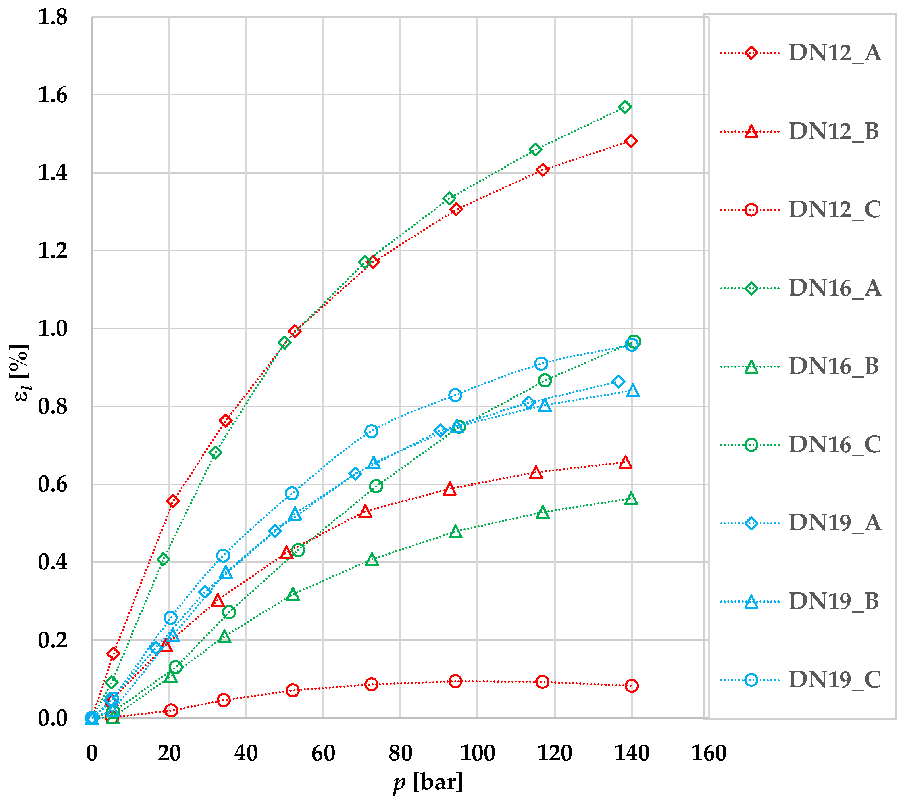
Figure 8 shows that the greatest length strain across all hoses is achieved by the hydraulic hose DN16_A, where the length strain was
εl = 1.57% at the maximum working pressure
pmax. The initial braid angle is
φin = 52.51 ± 0.02° and the change in braid angle is Δ
φ = 1.18°. A similar length strain was achieved for DN12_A hose where the length strain was
εl = 1.54% at maximum working pressure
pmax and the initial angle
φin = 51.01 ± 0.08°. This hose achieved the largest change in the braid angle Δ
φ = 1.35° of all the hydraulic hoses tested. The length strains
εl versus pressure
p curves are similar for these hoses. For comparison, the hydraulic hose DN12_C achieved the smallest length strain
εl = 0.11% at maximum working pressure
pmax. This hose experienced the smallest change in the braid angle Δ
φ = 0.32° of all the hydraulic hoses tested.
When comparing hydraulic hoses with an inner diameter din = 13 mm, it can be seen that the DN12_A hose with the largest deviation of the initial braid angle φin = 51.01 ± 0.08° from the neutral braid angle achieves the largest change in braid angle Δφ = 1.35° and the largest length strain εl = 1.54%. The hose DN12_B shows a smaller change in braid angle Δφ = 0.81°, which corresponds to a smaller change in length strain εl = 0.67%. The smallest change in braid angle Δφ = 0.32° and the smallest change length strain εl = 0.11% occurred in hose DN12_C, where the initial braid angle φin = 53.80 ± 0.05° was closest to the neutral braid angle. In the evaluation of the dependence εl = f (p) for hydraulic hoses DN12_A, DN12_B and DN12_C, all of the hypotheses mentioned above were confirmed.
A similar trend can be observed when comparing hydraulic hoses with an internal diameter din = 16 mm. Hydraulic hoses with an inner diameter din = 16 mm have similar initial braid angles φin, but each achieves a different change in the braid angle Δφ at maximum pressure pmax. The DN16_A hose that achieved the greatest change in braid angle Δφ = 1.18° also achieved the greatest length strain εl = 1.57%. It can also be observed that the hose DN16_C has a change in the braid angle Δφ = 0.97° and length strain εl = 0.97%. The smallest change in the braid angle Δφ = 0.54° and length strain εl = 0.56% was achieved by hose DN16_B. Although DN16_A has a larger initial braid angle φin than DN16_B, it achieves a greater change in the braid angle Δφ and a greater length strain εl. This could be due to the smaller wall thickness s of DN16_A.
In the comparison of hydraulic hoses with an inner diameter din = 19 mm, similar length strains depending on the working pressure can be observed. These hoses have a similar initial braid angle φin and show a similar change in the braid angle Δφ. The exception is hydraulic hose DN19_C with a smaller initial braid angle φin = 52.26 ± 0.03°, which shows the largest change in braid angle Δφ = 1.18° and the largest length strain εl = 0.96%.
From the resulting dependencies of the length strain εl with respect to the working pressure p and the measured braid angles, it is evident that the initial braid angle φin, the change in the braid angle Δφ and the thickness s of hydraulic hose have significant effects on the length strain εl. This can be seen from a comparison of the DN16_A and DN12_A hoses with different internal diameters din, where there is a significant length strain εl. In addition, the material properties of the steel braid and rubber and the manufacturing technology can also have an effect.
4.2. Evaluation Tensile Force Depending on Working Pressure
The measurement of the dependence of the tensile force
FT on the fluid pressure
p was performed. In this case, the bottom end of the hose was connected to the force sensor without the ability to move the hose in the longitudinal axis. The initial braid angle, the end braid angle and the braid angle change were evaluated as in the previous case.
Table 6 shows a summary of all the initial
φin braid angles, the end
φen braid angles and the Δ
φ braid angle changes achieved by each hydraulic hose in this measurement. It can be seen in the table that as the working pressure
p increased, there was less change in the braid angle Δ
φ than in the previous experiment (
εl =
f (
p)). This is due to the tight fit of both hose ends.
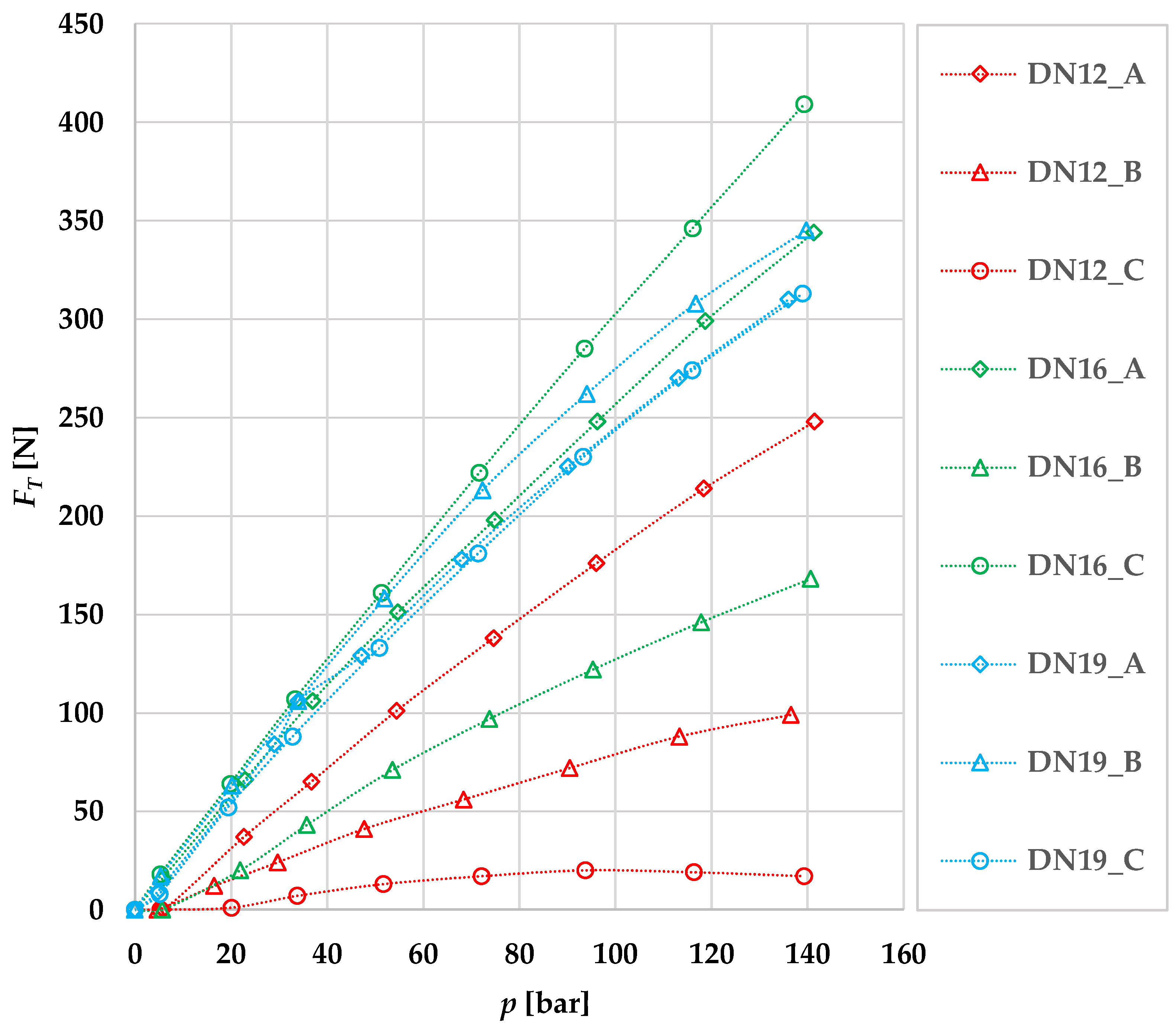
Figure 9 shows the dependencies of the tensile force
FT on the working pressure
p for all hydraulic hoses evaluated. The resulting dependencies show significant changes in the tensile force
FT as the working pressure
p increases. The initial braid angle
φin has a major influence. Another factor may be the change in the braid angle Δ
φ, which is dependent on the increasing working pressure
p. The thickness
s of the hose itself must also be considered. The last aspect that can have a significant effect on the resulting tensile force
FT is the inner diameter
din, because as the inner diameter
din increases, the area on which the working pressure
p acts increases. The graph shows that the hydraulic hose DN16_C, which has an initial braid angle of
φin = 52.77 ± 0.08° and a change in braid angle of Δ
φ = 0.64°, achieved the highest tensile force
FT = 409 N at the maximum working pressure
pmax. The smallest tensile force
FT = 17 N was achieved by hose DN12_C, which had the smallest deviation of the initial braid angle
φin = 53.80 ± 0.05° from the neutral braid angle
φN. The change in braid angle Δ
φ = 0.13° is significantly the smallest of all hoses.
In the comparison of hydraulic hoses with an inner diameter din = 13 mm, it can be observed that hose DN12_A with the largest deviation of the initial braid angle φin = 51.01 ± 0.08° from the neutral braid angle achieved a change in the braid angle Δφ = 0.77° and a tensile force FT = 248 N. Hose DN12_B achieved a smaller change in the braid angle Δφ = 0.69°, but the initial braid angle φin = 53.05 ± 0.10° was greater. This factor influences the tensile force FT = 99 N at the maximum working pressure for hose DN12_B. The smallest tensile force FT = 17 N at maximum working pressure was achieved with hose DN12_C, which has the largest initial braid angle φin and the smallest change in braid angle Δφ. In the evaluation of the dependence of FT = f (p) for hydraulic hoses DN12_A, DN12_B and DN12_C, the above hypotheses were confirmed.
In the comparison of hydraulic hoses with inner diameter din = 16 mm, the hose DN16_C achieved the highest tensile force FT = 409 N at the maximum working pressure pmax. At the same time, this hose experiences a change in the braid angle Δφ = 0.64°, which is the largest in the comparison of hoses with the same inner diameter din = 16 mm. Hose DN16_A achieved a tensile force FT = 344 N at maximum working pressure pmax with the change in the braid angle Δφ = 0.46°. The significantly smaller tensile force FT = 176 N at maximum working pressure pmax and a change in the braid angle Δφ = 0.35° was achieved with hose DN16_B, and thus the above hypotheses were confirmed.
In the comparison of hydraulic hoses with inner diameter din = 19 mm, the hose DN19_B achieved the tensile force FT = 345 N with a braid angle change Δφ = 0.57° and an initial braid angle φin = 53.03 ± 0.05°. Hydraulic hoses DN19_A and DN19_C have a similar trend of dependence of the tensile force FT on the pressure p. Hose DN19_A achieved a tensile force FT = 310 N with a change in the braid angle Δφ = 0.31° and an initial braid angle φin = 53.62 ± 0.06°. Hose DN19_C achieved a tensile force FT = 313 N with a change in the braid angle Δφ = 1.11° and an initial braid angle φin = 53.62 ± 0.06°. In the evaluation of the dependence FT = f (p) for hydraulic hoses DN19_A, DN19_B and DN19_C, the above theory was not confirmed. The hose DN19_C did not achieve the highest tensile force FT due to the largest change in the braid angle Δφ and the smallest initial braid angle φin. Furthermore, as already mentioned, the different material properties and the manufacturing process of the hoses may also influence the resulting dependencies.


