Article

Model and Parameter Study of Limestone Decomposition Reaction

1
Zhongye Changtian International Engineering Co., Ltd., Changsha 410205, China
2
School of Mechanical and Vehicle Engineering, Hunan University, Changsha 410205, China
*
Author to whom correspondence should be addressed.
Processes 2024, 12(1), 150; https://doi.org/10.3390/pr12010150
Submission received: 8 December 2023 / Revised: 3 January 2024 / Accepted: 4 January 2024 / Published: 8 January 2024

Abstract

:
To address the problem that there are many limestone particle decomposition reaction models and it is difficult to accurately select the appropriate one, this paper established two typical one-dimensional unsteady numerical calculation models for single-particle limestone decomposition, coupling the convective heat transfer, thermal conduction, and CO2 mass transfer processes. Two numerical calculation models were solved through the Matlab R2021a platform, and the internal temperature, CO2 concentration distribution, and decomposition reaction rate of the limestone particles during the period from the beginning of temperature rise to the end of decomposition were obtained. Compared with the experimental data, Model 1 has a better agreement with a relative error of less than 10%. The simulation results have shown that the average decomposition reaction rate is 20% higher than the average mass transfer rate. As the particle size increases from 20 mm to 80 mm, the time required for temperature rise in the initial stage changes from 6.6 min to 42.7 min. It is noted that the CO2 volume fraction increment increases by 0.42% with a particle size of 80 mm and a heating temperature of 1050 °C, indicating that the influence of the distribution of CO2 on the limestone decomposition may not be ignored.

1. Introduction

As an important industrial material, lime, mainly composed of CaO, is widely used in metallurgical processes [1,2,3], construction [4], power supply [5], and other industries. For example, in the metallurgical industry, it is used for adjusting alkalinity, desulfurization, decarburization, protecting the furnace, etc., which makes it an indispensable material [6]. Lime is mainly obtained by calcining limestone at high temperature. The decomposition reaction rate of limestone is highly sensitive to the calcination temperature, atmosphere, etc. In order to better predict the reaction process of limestone, many scholars have conducted extensive research on the decomposition kinetic mechanism of limestone [7,8,9,10].
Firstly, researchers have carried out a large number of experimental studies on limestone powder of micrometer level, establishing various reaction mechanism models. Li Jiarong conducted experiments using limestone powder of 0–45 μm, revealing that the limestone decomposition conforms to a two-dimensional random nucleation and subsequent growth model, and the apparent activation energy is around 200 kJ/mol [11]. Zhang Lina et al. studied the thermal decomposition process of limestone powder of 900 μm using the TG-DSC method, obtaining an activation energy of 193.98 kJ/mol and suggesting that the decomposition process of the size scope belongs to a three-phase boundary reaction model [12]. Zhang Wenxian’s experimental results indicated that in a high concentration of CO2, the decomposition of limestone follows the two-dimensional random nucleation and subsequent growth model, and the calculated activation energy is between 200 and 400 kJ/mol [13]. Jiang Ting studied the calcination of limestone in a CO2 atmosphere, calculating an average activation energy of 184.345 kJ/mol for the decomposition of limestone [14]. Chen Jiangtao et al. studied the calcination characteristics of limestone particles at different temperatures and discovered that the calcination reaction of fine particles of limestone is mainly controlled by a chemical reaction mechanism in a nitrogen atmosphere [15]. According to the above research, it can be found that the apparent activation energy for decomposition is around 200 kJ/mol in different atmospheres.
On the basis of research on limestone powder of micrometer level, some scholars have also conducted experiments on large particle sizes. Wang Liyou studied the calcination of 4–25 mm limestone particles at ultra-high temperatures. Their research revealed that during the decomposition process, there is a three-layer structure consisting of a slag layer, lime layer, and unreacted limestone, as the decomposition reaction progresses from the outside inwards [16]. Cao Jing et al. studied the decomposition characteristics of limestone with a particle size of less than 2 mm in a variety of CO2 concentrations using a thermogravimetric differential scanning calorimeter. They found that a higher CO2 partial pressure increases the activation energy of the limestone decomposition reaction [17]. Chen Kaifeng et al. studied the limestone calcination at temperatures above 1200 °C and obtained an activation energy lower than 200 kJ/mol [18]. Hills et al. conducted experiments on large limestone particles of 10 mm and studied the reaction rate under different heat temperatures and environmental atmospheres (CO2 concentration). These achievements provide a large amount of data for model verification for later scholars [19].
According to observations of the decomposition reaction process of large-particle limestone, researchers have established shrinkage core models, and have further conducted extensive simulations on the characteristics of the limestone particle decomposition at different conditions. Among them, the shrinkage core models can be divided into two categories. The first category is the three-interface method proposed by Bluhm-Drenhaus T et al., which assumes that the diffusion rate of CO2 inside particles is equal to the reaction rate. This assumption simplifies the solution for CO2 diffusion [20]. Liu Qian et al. applied an integrated parameter method (without considering internal temperature distribution) based on this model to numerically solve the decomposition rate of limestone particles. Their results are consistent with experimental data at high temperatures but show increasing deviations as temperature decreases [21]. Wang Gan et al. adopted this method to the numerical simulation of the iron ore sintering process, and their calculated data such as flue gas composition and temperature matched the experimental values well [22].
The second type is the single-interface method proposed by Krause Bastian et al., which requires solving the CO2 diffusion rate equation inside the particle [23]. Jiang Binfan et al. simulated the limestone decomposition process based on this reduced core model, and found that the influence of temperature and CO2 partial pressure on limestone decomposition rate is basically the same as their previous experimental results [24]. Further, Krause Bastian et al. [23] and Zhou Ping et al. [25] used this reduced core model to conduct simulation research on the heat and mass transfer process in lime kilns. Krause Bastian et al. simulated limestone particles using the discrete element method to consider the concentration distribution of CO2 inside the particle, and validated the numerical calculation results through data such as temperature and flue gas composition at different heights in the kiln. By using the second model, Zhou Ailan et al. conducted a bunch of simulations which can accurately predict the pyrolysis process of ultra-fine limestone [26].
Although the above two models have been widely used, little attention has been paid to their differences or limitations. And the selection criteria for the two models are scarcely seen in existing research. The selection of these two models may rely on the CO2 concentration, temperature, or particle size. In order to explore the effect of these factors and throw light on the application of the two typical models, we launched a series of studies. First, we built numerical models of limestone decomposition processes based on the two reduced core models. Then, we carried out experiments to validate the models. Further, we conducted simulations and an analysis of these main influencing parameters to provide the theoretical basis and guidance for the selection and application of limestone particle decomposition reaction reduced core models in industrial modeling.

2. Limestone Decomposition Reaction Model

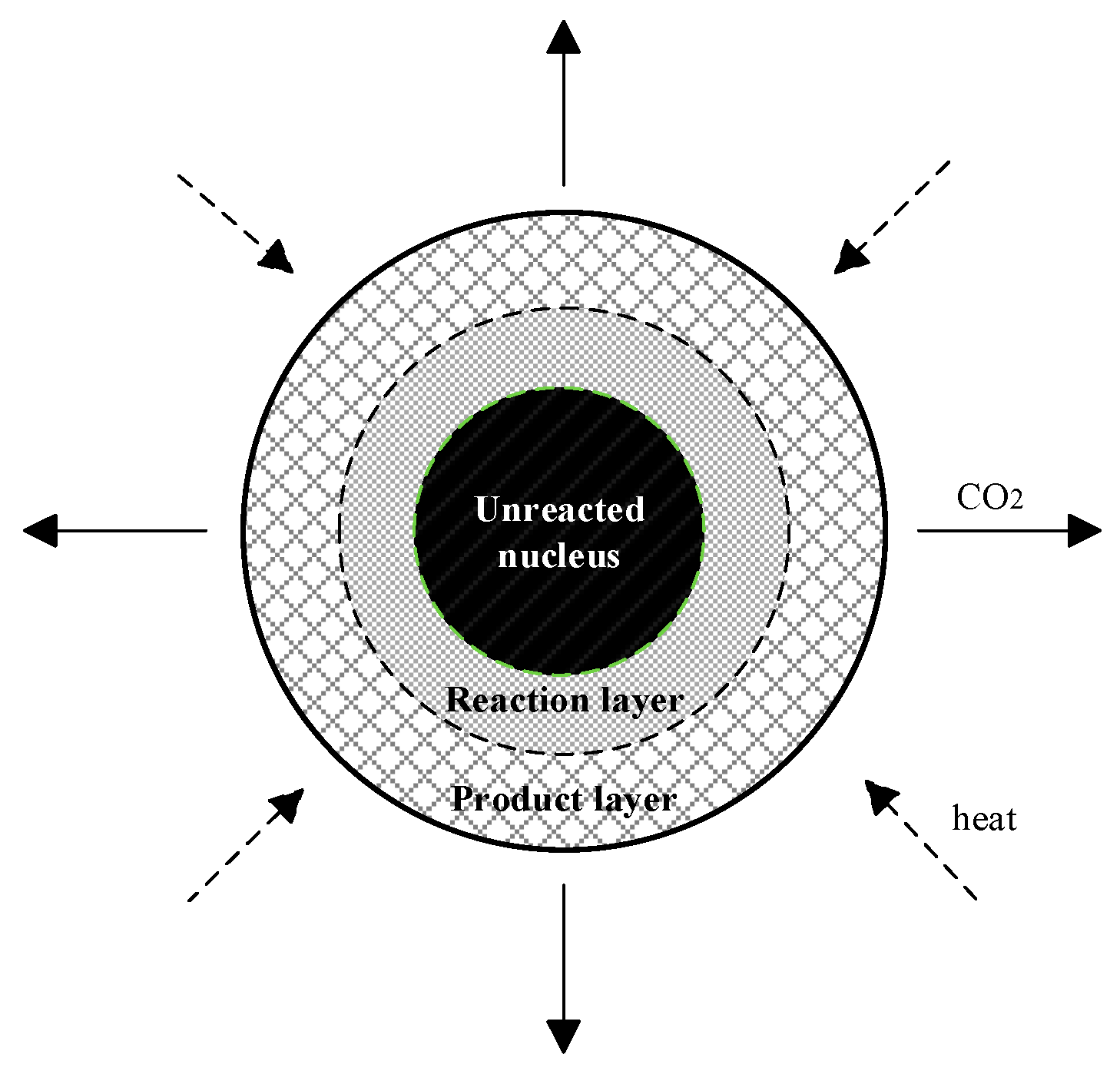
2.1. Physical and Chemical Process Analysis

The decomposition process of limestone calcination in the lime kiln is mainly composed of three parts: heat transfer, mass transfer, and decomposition reaction. ① Heat transfer process: Convection heat transfer occurs between the hot gas and the outer surface of the limestone block in the furnace, and then the heat is conducted from the surface to the inside of the limestone particles. ② Decomposition reaction process: The main component of limestone is CaCO3, and the decomposition reaction of limestone is converting CaCO3 into CaO and CO2 at high temperatures. ③ Mass transfer process: CO2 generated during the decomposition reaction of CaCO3 gradually diffuses inward and outward of the limestone particles through the pores. The decomposition reaction equation is
CaCO3→CaO+ CO2
In the shrinking core model, the limestone is considered as a regular sphere, and its completed decomposition takes a certain amount of time. During the decomposition, the reaction first occurs on the outer surface of the limestone particle. As the reaction progresses in the limestone particles, the reaction layer slowly advances inward. Therefore, the limestone sphere can be divided into an ash layer (CaO), a reaction layer, and an unreacted core (CaCO3), from the outside to the inside. The schematic diagram of the limestone decomposition process is shown in Figure 1.

2.2. Mathematical Model

2.2.1. Thermal Conduction Model

A one-dimensional unsteady-state differential equation in spherical coordinates is used to describe the heat conduction within the limestone particle. Assuming that the outermost radius of the limestone is r0, the heat conduction equation is shown in Equations (2)–(9) [2,3], where Equation (5) [22] is the empirical formula of the Nusselt number in the decomposition process of CaCO3:
ρ c p T t = 1 r 2 r ( λ r 2 T r ) + S c
S c = R h q V
h = N u · λ g 2 r 0
N u = 2 + 1.1 P r 1 / 3   R e 2 / 3
R e = ρ g v g r 0 μ g
P r = μ g c p , g λ g
The boundary conditions for the heat conduction are as follows:
r = r 0 , λ T r r = r 0 = h ( T f T s )
r = 0 , λ T r r = 0 = 0

2.2.2. Decomposition Reaction Kinetics Model

According to the research of Chen Hongwei et al. [27], the decomposition rate of the limestone is closely related to the CO2 diffusion. The decomposition rate of the limestone particle of the shrinking core model can be written as Formula (10):
R = π d l 2 ( C C O 2 e C C O 2 ) 2 4.1868 K l K r , l R g T
The  K l  and  K r , l  are as shown in Equations (11) and (12) [24]:
K l = 101325 exp ( 7.079 9000 T )
K r , l = 1.01 × 10 9 exp ( 232000 R g T )

Model 1

In model 1, the distribution of CO2 inside the limestone particle needs to be calculated. Similar to the heat transfer equation, a one-dimensional unsteady differential equation is used to describe the mass transfer in a limestone particle, as shown in Equation (13):
C t = 1 r 2 r D e r 2 C r + m c ˙
The boundary conditions for the mass transfer are as follows:
r = r 0 , C r = r 0 + = C g × φ
r = r r e c , m c ˙ = R V
Considering that the pores generated by the decomposition of limestone are much smaller than the average free path of gas molecules, the diffusion of CO2 molecules in the mineral matrix can be considered as Knudsen diffusion. The mass transfer coefficient can be determined by Equation (16) [24]:
D e = d p 3 ( 8000 R g T π M C O 2 ) 0.5

Model 2

According to Masoud Pahlevaninezhad et al. [3], the decomposition process of limestone can be simplified based on the core shrinkage model, assuming that the CO2 generation rate at the reaction layer is equal to the CO2 diffusion rate, i.e., the limestone reaction is a series reaction. Therefore, the CO2 concentration at the reaction interface can be represented by the CO2 concentration in the ambient atmosphere, instead of being solved by the mass transfer equation. Equation (10) can be rewritten as follows:
R = π d l 2 ( C C O 2 e C C O 2 g ) d p S h . D C O 2 + d p ( d p d l ) d l D e f f . C O 2 + 2 × 4.1868 K l K r , l R g T ( d p d l ) 2

3. Numerical Solution of the Model

3.1. Calculation Parameters

The parameters required for calculating the decomposition process of limestone are shown in Table 1.
Other thermal physical property parameters, such as the specific heat capacity of CaCO3 and CaO, are calculated using the relevant empirical formulas.

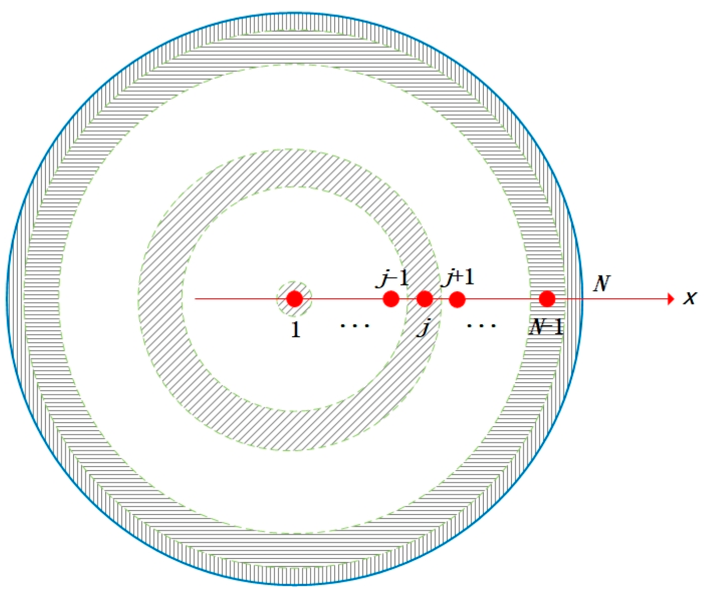
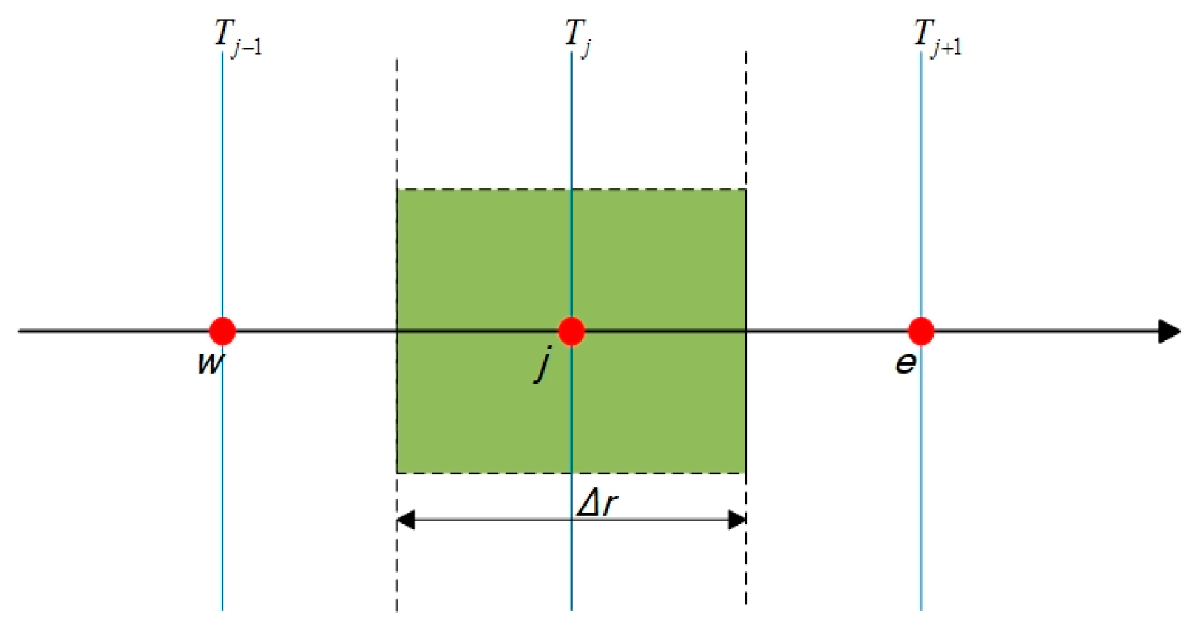
3.2. Discretization of Domain and Equations

To perform numerical calculations on the above-established model, the computational domain is first divided into grid cells. In this article, the limestone particle is equally divided into N annular micro-domains along the radial direction, as shown in Figure 2. The node j at the central location of the annular region represents the whole cell region. j = 1 represents the limestone particle center, while j = N represents the outer surface of the limestone particle.
Based on the divided grid, the finite volume method (FVM) is used to integrate the mass and energy conservation equation within the grid cell for equation discretization, as shown in Figure 3. To avoid the instability that may be caused by an explicit discretization scheme, both equations use a fully implicit discretization scheme [30].
Equations (2) and (11) were integrated and discretized, respectively, by using FVM at each grid node j. The specific derivation of Equation (2) is presented as follows:
t t + Δ t w e r 2 ρ c p T t d r d t = t t + Δ t w e r ( λ r 2   T r ) d r d t t t + Δ t w e r 2 h q R V d r d t
Assuming the  h q R V  as a constant value, the implicit scheme was adopted to discretize Equation (18):
r e 3 r w 3 3   ρ c p ( T j n + 1 T j n ) = ( λ r e 2 T j + 1 n + 1 T j n + 1 Δ r e λ r w 2 T j n + 1 T j 1 n + 1 Δ r w ) Δ t r e 3 r w 3 3 h q R V Δ t
Algebraic equations for different grid nodes are as shown below:
j = N (external grid points)
The boundary condition of the external grid points is as shown in Equation (20):
λ T r r e = h ( T f n + 1 T N n + 1 )
where  T f T N  are the temperature of the ambient atmosphere and grid point N, respectively. Substituting Equation (20) into Equation (19), the algebraic equation at external grid points is shown in Equation (21):
( r 0 ) 3 ( r 0 0.5 Δ r ) 3 3 ρ c p ( T N n + 1 T N n ) = ( ( r 0 ) 2 h ( T f n + 1 T N n + 1 ) λ ( r 0 0.5 Δ r ) 2 T N n + 1 T N 1 n + 1 Δ r w ) Δ t ( r 0 ) 3 ( r 0 0.5 Δ r ) 3 3 h q R V Δ t
j = 1 (spherical center point)
( 0.5 Δ r ) 3 0 3 ρ c p ( T 1 n + 1 T 1 n ) = ( λ ( 0.5 Δ r ) 2 T 2 n + 1 T 1 n + 1 Δ r Δ t ( 0.5 Δ r ) 3 0 3 h q R V Δ t
j = 2,3, …, N − 1 (inner grid points)
( j 0.5 ) Δ r ) 3 ( ( j 1.5 ) Δ r ) 3 3 ρ c p ( T j n + 1 T j n ) = ( λ ( ( j 0.5 ) Δ r ) 2 Δ r e ( T j + 1 n + 1 T j n + 1 ) λ ( ( j 1.5 ) Δ r ) 2 Δ r w ( T j n + 1 T j 1 n + 1 ) ) Δ t ( ( j 0.5 ) Δ r ) 3 ( ( j 1.5 ) Δ r ) 3 3 h q R V Δ t
The same derivation was conducted for Equation (11) and no further elaboration.

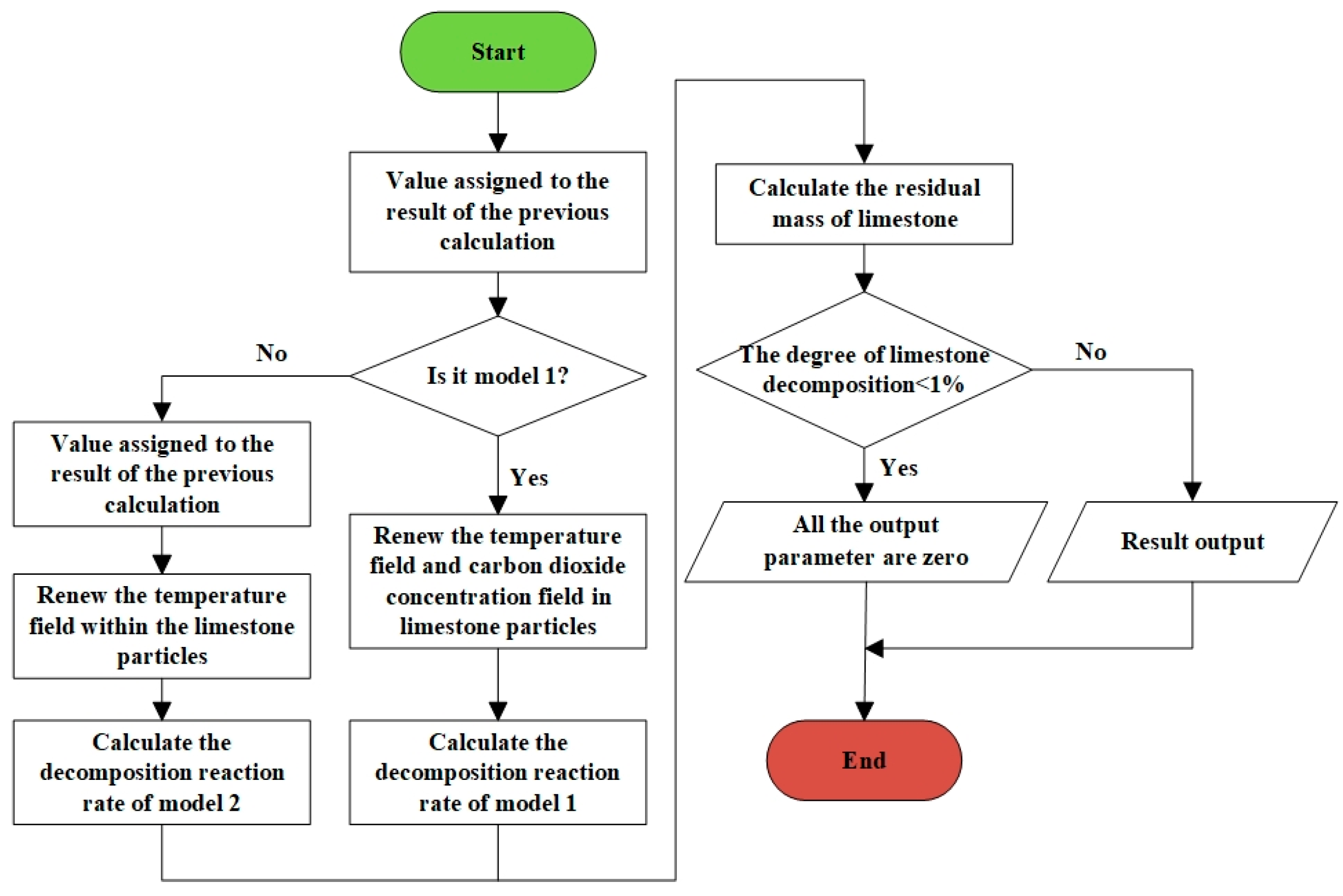
3.3. Numerical Solution Method and Calculation Flowchart

The Thomas algorithm was used to solve the tridiagonal matrix algebraic equation obtained from the equation discretization in Section 3.3. The calculation process of the numerical model for the limestone decomposition reaction is shown in Figure 4. First, the temperature field and CO2 concentration field are, respectively, solved; then, the reaction rate is calculated and the position of the reaction layer is obtained. Secondly, the temperature field and the CO2 concentration field are updated based on the reaction heat. Thirdly, the reaction rate is calculated and the reaction layer position is updated. Steps 2 and 3 are repeated until the limestone particle is completely decomposed. The calculation program includes the reaction sub-models for both Model 1 and Model 2. Model 1 requires the calculation of the CO2 concentration field, as shown in Figure 5.

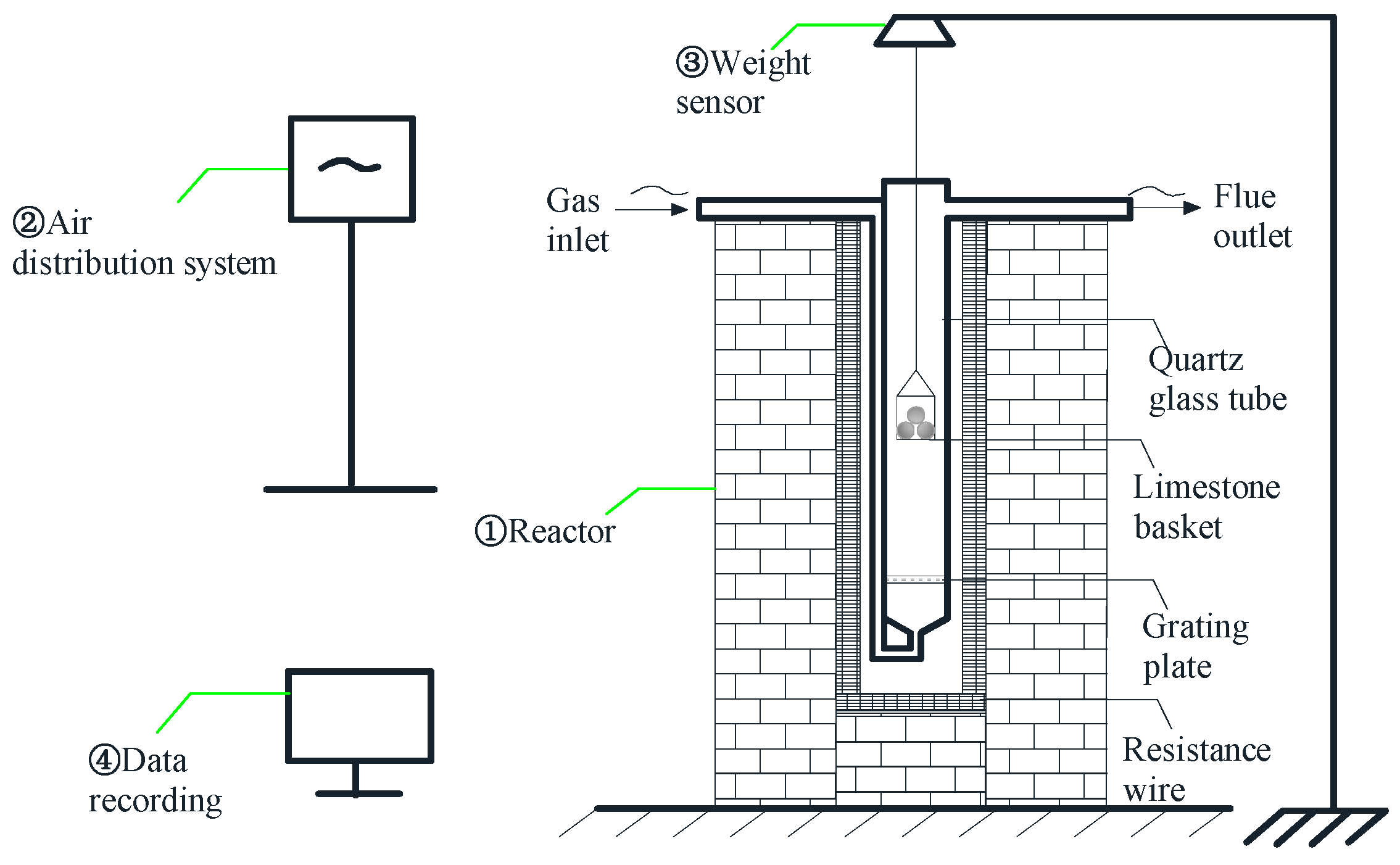
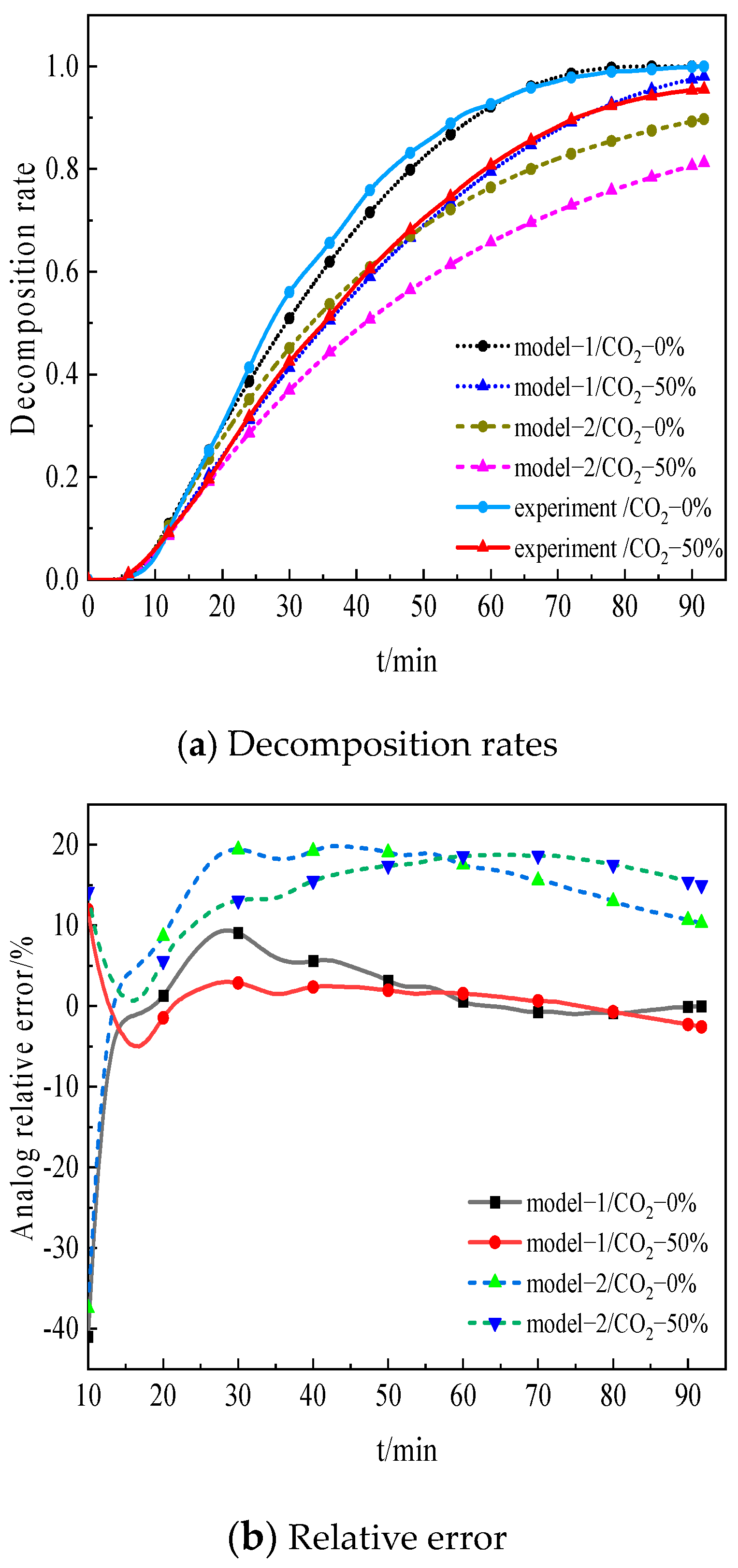
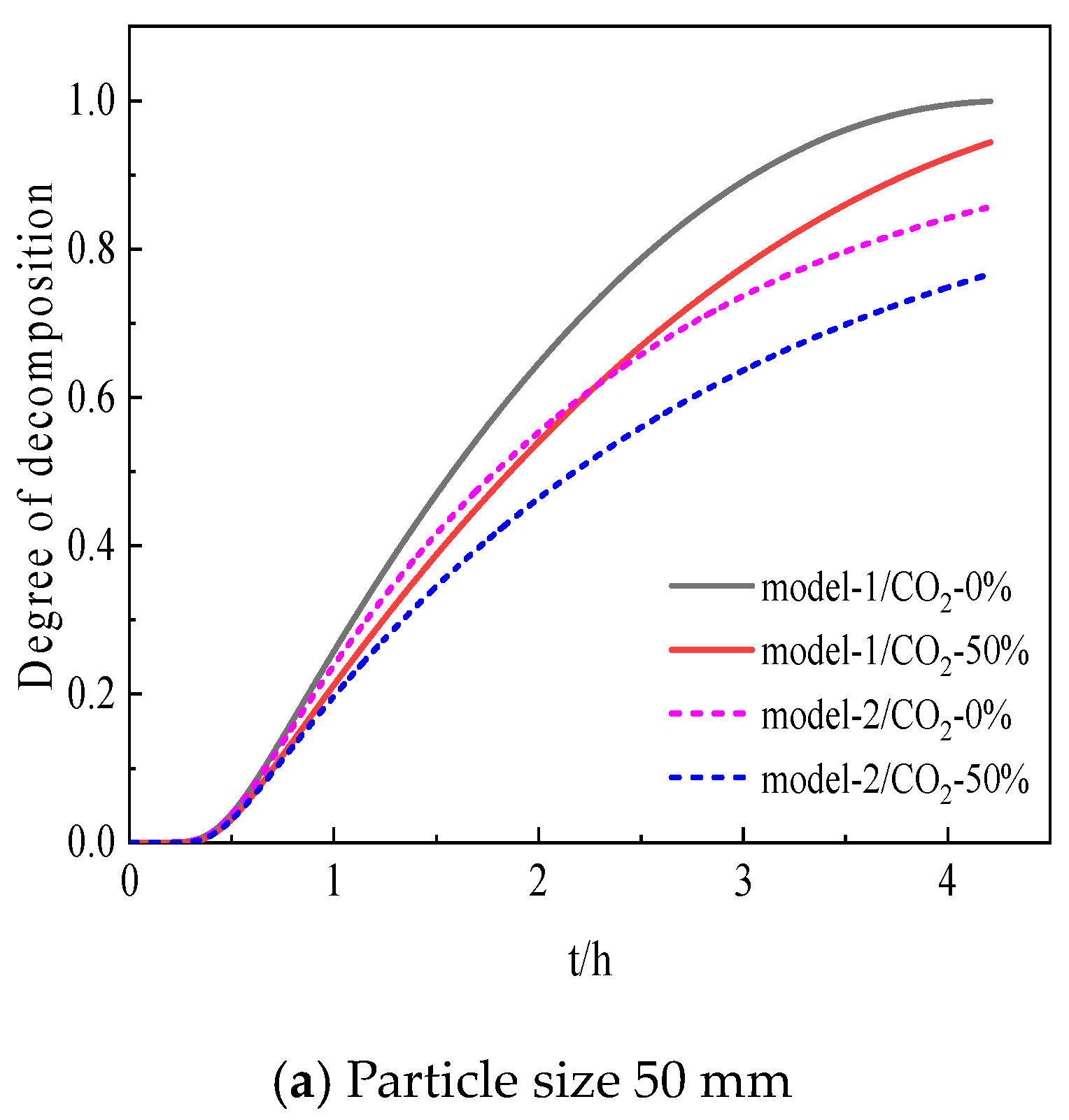
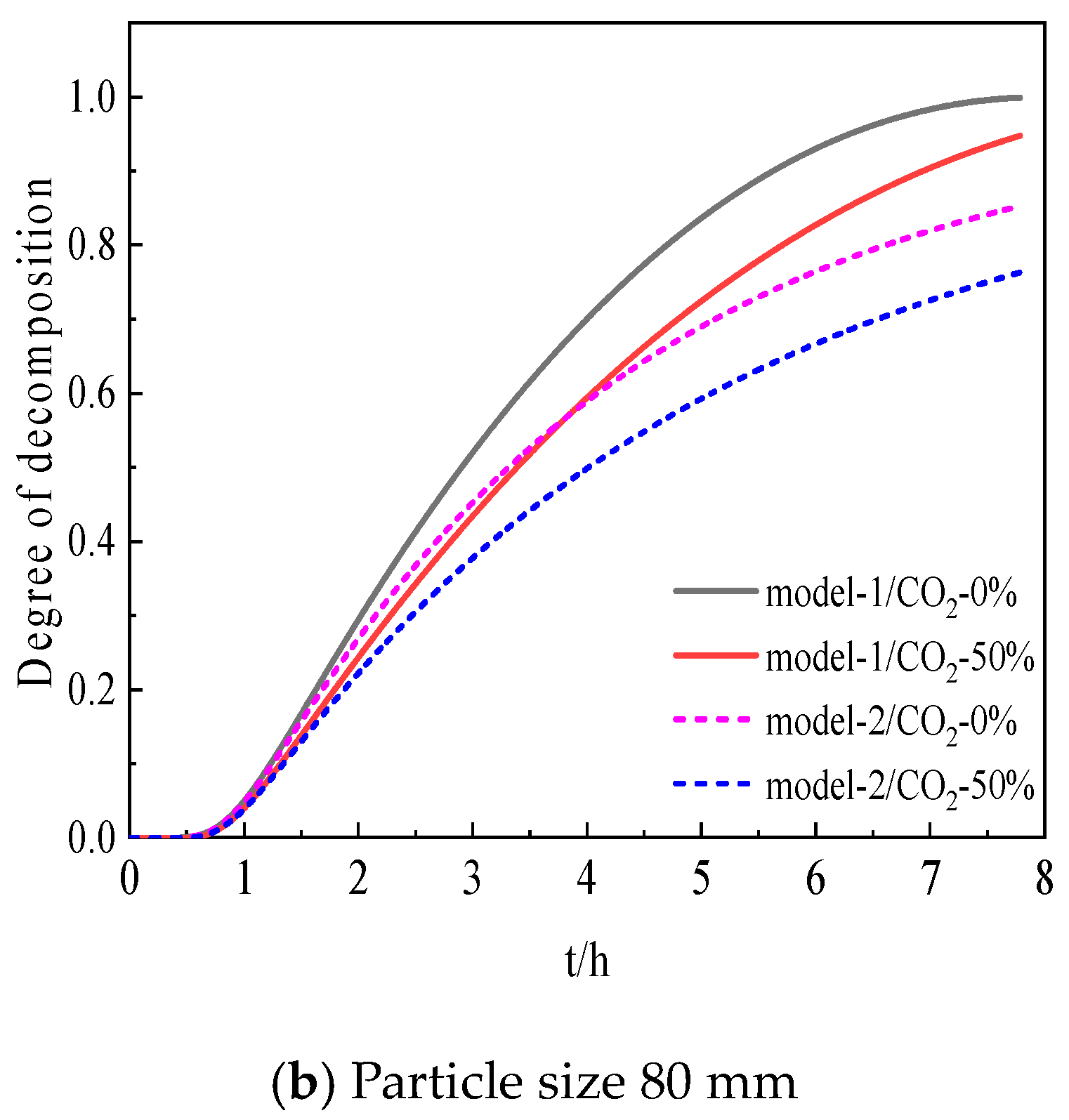
4. Model Validation of Limestone Decomposition

To verify the calculation accuracy of the two models, multiple experiments of limestone particle decomposition were conducted by using a kinetic furnace. The average value of multiple experiment data was used to verify the model calculation results. The experimental platform is shown in Figure 6, including the reaction furnace, gas distribution system, weight sensing system, and data recording system. The reaction furnace is heated using a resistance wire, and the temperature of the gas inside the quartz glass tube is measured using a thermocouple. The limestone particles are placed in a quartz glass hanging basket, which has small holes at the bottom and sides to ensure sufficient contact between the limestone particles and the environmental gas. The hanging basket is placed inside the quartz glass tube. N2 and CO2 gas are mixed in a certain proportion using the gas distribution system before entering the top of the side tube and passing through the bottom into the quartz glass tube, and then exiting through the outlet, providing a stable reaction atmosphere for limestone decomposition. The top of the hanging basket is connected to the weight sensing system, which has a measurement accuracy of 0.01 g. In order to reduce the measurement error caused by the deformation or inclination of the connecting rod between the hanging basket and the weight sensor, the connecting rod is made of quartz glass which has a strong resistance to deformation under high temperature and is vertically fixed at the sensor probe with two screws. The other end of the connecting rod was designed as a concave structure which can completely lock the hanging basket. Moreover, a grating plate is fixed at the bottom zone below the hanging basket, as seen in Figure 6, to reduce the fluctuation of the inlet gas which may cause the connecting rod to swing and further affect the measurement accuracy.
Before the experiment, several tests were conducted to calibrate the weight sensor within a range of temperatures from room temperature to 1200 °C. During the limestone particle reaction process, the weight decreases continuously until the reaction is completed and no longer changes. The weight data of limestone particles and temperature data are recorded by the data recording system.
The specific experimental conditions were as follows: ① the gas temperature in the reaction furnace was stabilized at 1050 °C; ② two different reaction atmospheres were prepared using pure 100%N2 and 50%CO2-50%N2; and ③ the size of the limestone particles was 15~25 mm. For each case, more than three tests were conducted. The weight of the basket and limestone particles as a whole was recorded every minute. By data analysis, the maximum mean square error of the weight value at each minute was about 4.2% which basically occurs at the end of the decomposition process. Fortunately, the average value was less than 2.1%. Finally, the average value of three or four tests was used for analysis in this paper.
Under the same reaction conditions, the two numerical models mentioned above were used to calculate the variation of limestone decomposition rate over time. The comparisons and results are shown in Figure 7. It can be found that model 1 shows a better agreement with the experimental data, with a relative error value of less than 10%. In other words, it shows more accuracy in predicting the main trend of the limestone decomposition process. Meanwhile, the limestone decomposition reaction rate calculated using model 2 is slower than the experimental data, which can be attributed to the assumption in model 2 that the reaction rate is equal to the CO2 mass transfer rate. In fact, the reaction rate is much higher than the CO2 mass transfer rate, as elaborately analyzed in Section 5. Moreover, the limestone decomposition reaction is much less related to the CO2 mass transfer rate or resistance compared with the iron ore reduction process. During the limestone decomposition reaction, the CO2 is only one of the products which may inhibit the decomposition rate. However, it does not directly participate in the reaction like the gas in the iron ore reduction process. The iron ore usually refers to magnetite and hematite, which are reduced by CO or H2 at high temperatures that can be accurately predicted by the core shrinkage model [31], because the gas has a strong influence over the iron ore reduction process by a direct interference into the reaction mechanism. Thus, the gas mass transfer rate would be a limiting factor to the reaction rate. In the following section, we will further study the changes of CO2 in limestone particles.

5. Parameter Study of Limestone Decomposition Model

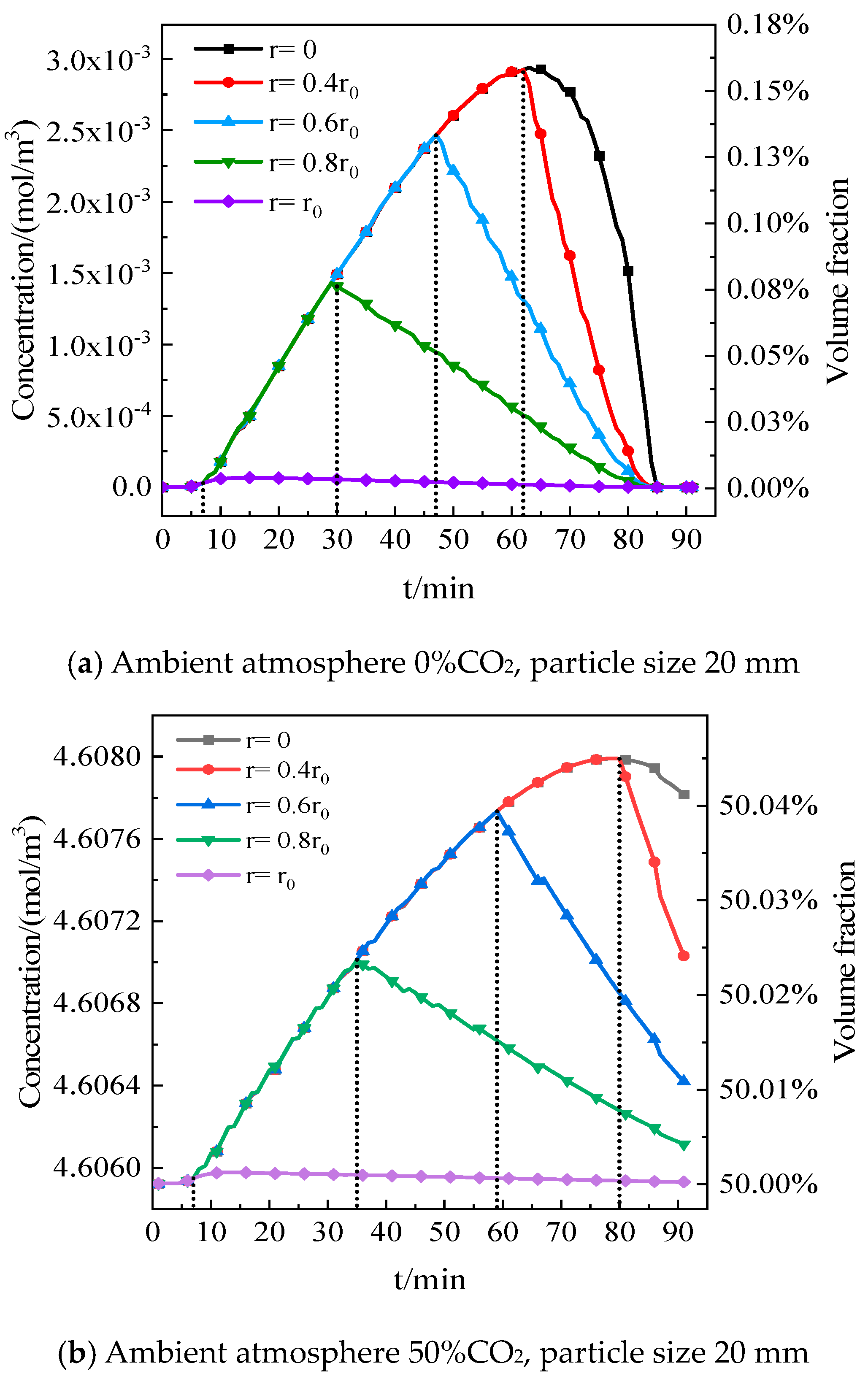
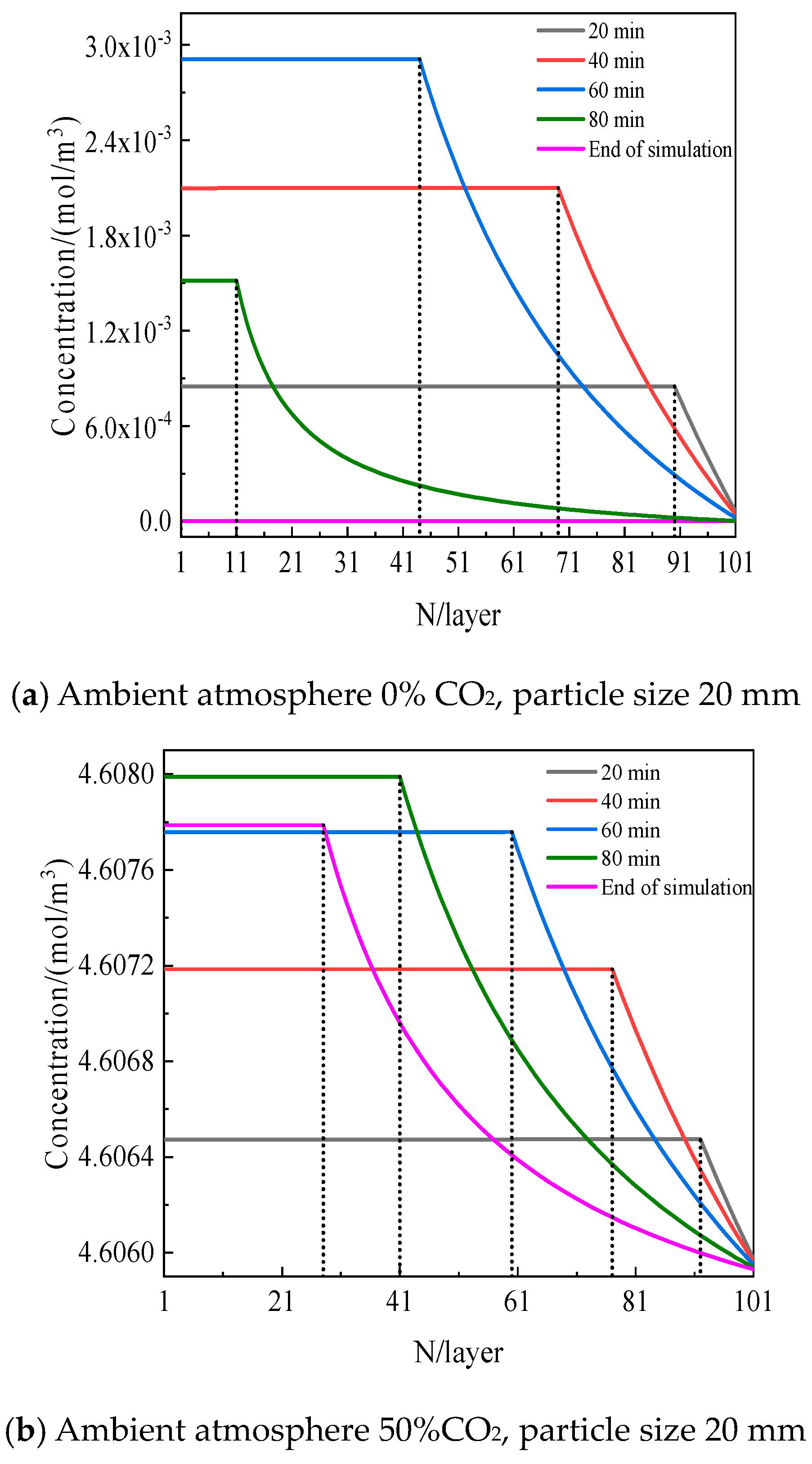
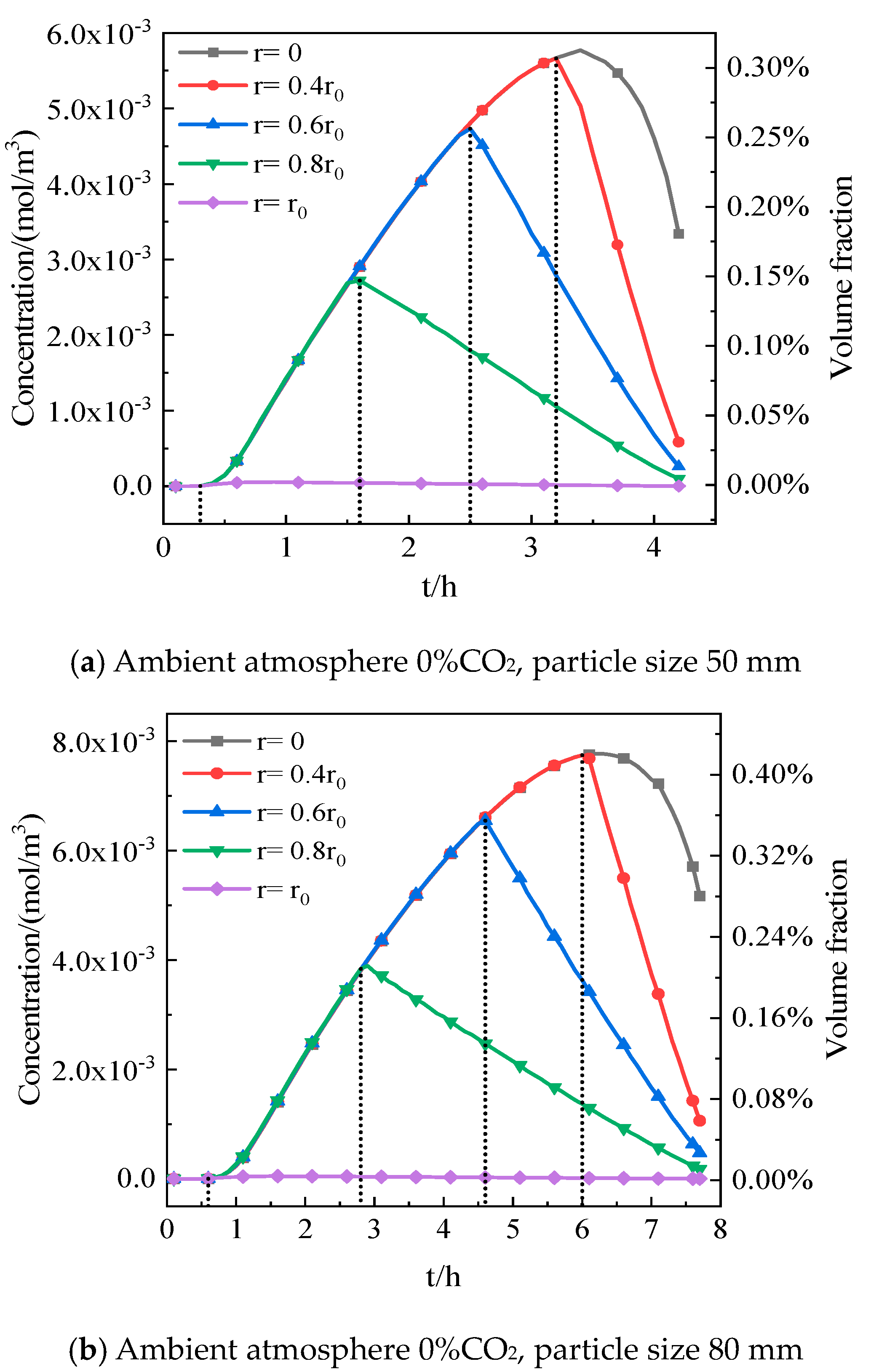
5.1. Effect of CO2 Distribution inside Particles on Decomposition

To explore the variation of CO2 inside the particles during the decomposition, simulations of the limestone particle reaction process with different particle sizes and ambient CO2 partial pressures were calculated by using Model 1. The results are shown in Figure 8 and Figure 9. It can be found clearly that in both atmospheres (0%CO2 and 50%CO2), the CO2 concentration in different layers inside the particle first increases and then decreases over the reaction time. This is consistent with the reaction progress, in which the CO2 concentration starts to decrease instantly as the layer completes its reaction (as marked by the dashed lines in Figure 8 and Figure 9). Additionally, the peak value of the CO2 concentration in each layer increases as the reaction approaches the particle center. This is due to the fact that the porosity of the ash layer is much greater than that of the unreacted layer, which means that the mass transfer resistance of CO2 is much higher in the unreacted layer. However, the generated CO2 diffuses inward and outward simultaneously, resulting in a gradual increase in the concentration of CO2 in the inner layer. Moreover, it is noted that when the ambient atmosphere is with 50%CO2, the maximum increase of CO2 concentration is slightly smaller than that of the 0%CO2 ambient atmosphere, but the main trend is similar. This is because the increase in CO2 concentration in the ambient atmosphere inhibits the decomposition reaction of limestone, leading to a slower accumulation rate of the CO2 diffusion in the inner layer, which is consistent with experimental results.
As shown in Figure 8, when the particle size of limestone is 20 mm, the variation in CO2 volume fraction under the two environmental atmospheres changes little, and the maximum increment is only about 0.16%. By increasing the particle size, the CO2 concentration increases inside the limestone. Figure 10 presents the CO2 concentration variation inside limestone with a particle size of 50 mm and 80 mm in 0%CO2 ambient atmosphere. It can be seen that as the particle size reaches 80 mm, the CO2 volume fraction increases by 0.42%. Therefore, it is recommended to consider the variation of the CO2 concentration when modeling the limestone decomposition.
To explore the assumption in Model 2 that the decomposition reaction rate and mass transfer rate are equal, the decomposition reaction rate (Equation (10)) and mass transfer rate were calculated under two environmental conditions. The mass transfer rate formula is as follows:
R s = 2 π d p d l D e C C O 2 g C C O 2 d p d l
where Rs represents the mass transfer rate within the CaO ash layer of limestone particles, mol/s. For convenience, the formula  1 R R s  was used to demonstrate the magnitude of the two rates, which were fitted as shown in Figure 11. When R is greater than Rs, the formula value is below zero. On the contrary, if R is smaller than Rs, the formula value is above zero. It can be found that during the early stage of limestone decomposition, the CO2 mass transfer rate is greater than the reaction rate due to the reaction layer being near the surface. However, the decomposition reaction rate increases rapidly and soon surpasses the mass transfer rate until the reaction ends. Overall, the average decomposition reaction rate is about 20% higher than the average mass transfer rate. Therefore, the assumption that the two rates are equal in Model 2 will underestimate the overall decomposition reaction rate of limestone. This assumption leads to the lower prediction accuracy of Model 2, which is consistent with the conclusion indicated in Figure 7.

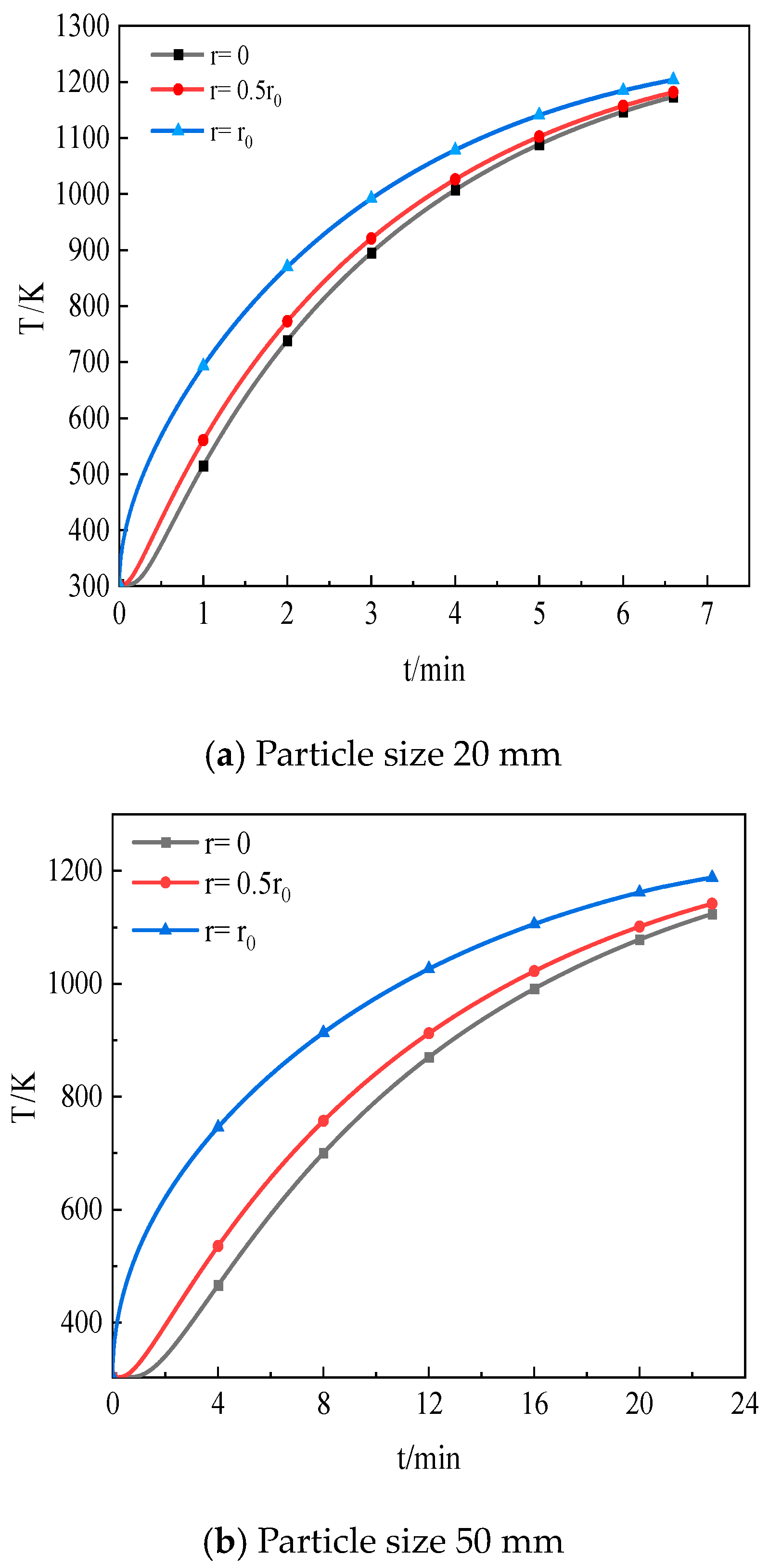
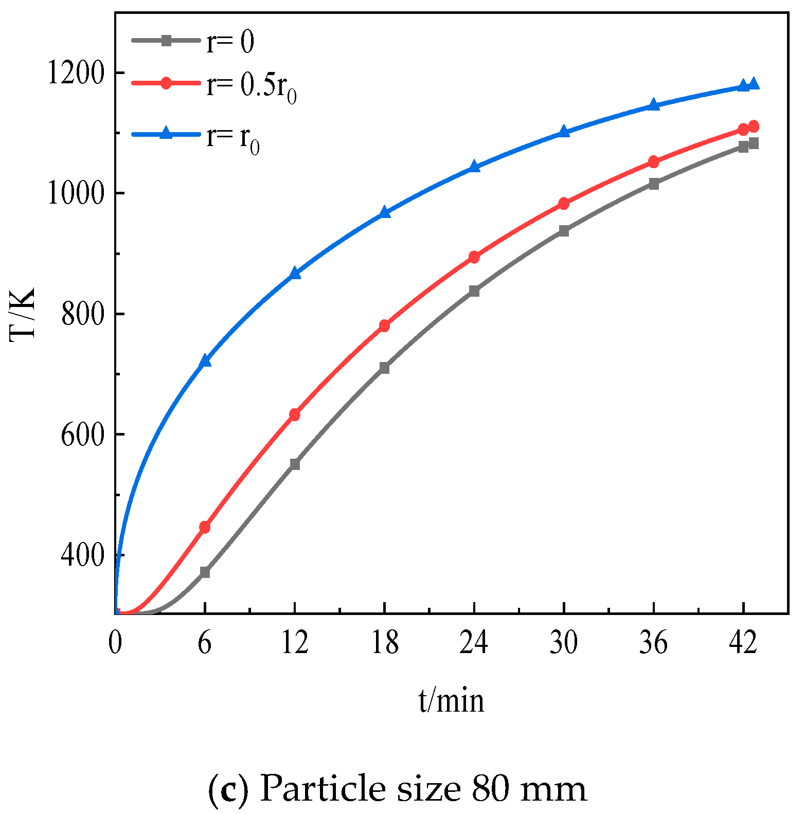
5.2. Influence of Limestone Particle Size on Decomposition

In industry, the limestone particle size has a larger range of 40~100 mm. Considering the difference between the two models, this subsection aims to further study the effect of the particle size on the decomposition reaction rate. The simulation results are shown in Figure 12. For different particle sizes, it is clear that the predicted trends of limestone decomposition rates over time for the two typical models are basically the same. It can be found that as the size of limestone particles increases, the time required for the limestone decomposition increases. For every 10% increase in particle size, the time required for the decomposition increases by about 11.3%.
In addition, it takes a section of time for the limestone particles to absorb heat and achieve the reaction temperature before the reaction occurs. The temperature variation inside the limestone particles during the initial stage (limestone decomposition rate < 1%) was simulated based on model 1. The results are shown in Figure 13. It can be seen that as the particle size increases from 20 mm to 80 mm, the time required for the temperature rise during the initial stage increases from 6.6 min to 42.7 min.

6. Conclusions and Outlook

Based on the mechanism of the limestone decomposition reaction, coupled with the convection heat transfer, thermal conductivity, and CO2 mass transfer processes, two typical one-dimensional unsteady numerical calculation models for single-particle limestone decomposition were established. In model 1, the CO2 diffusion rate was solved using the mass transfer equation. In model 2, it was assumed that the CO2 diffusion rate was equal to the reaction rate. Numerical calculations of the two models under various conditions were conducted. By means of the analysis of the simulation results and experimental data, the main conclusions were obtained as follows:
(1)
The simulation results of model 1 show better agreement with the experimental data, with a relative error of less than 10% overall.
(2)
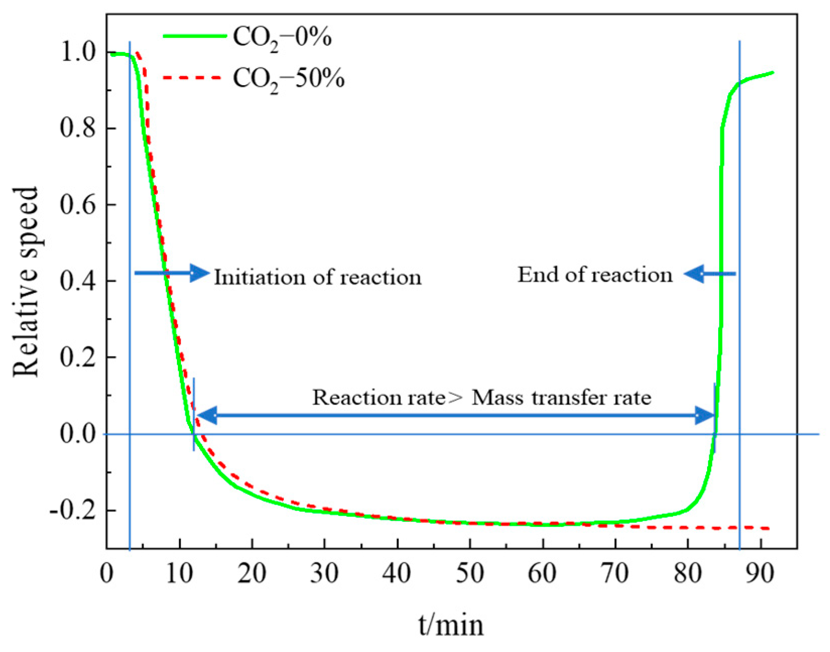
The average decomposition reaction rate is greater than the average mass transfer rate, and the average reaction rate is about 20% higher than the average mass transfer rate.
(3)
Compared to the ambient CO2 volume fraction outside the particle, the maximum increment of the CO2 volume fraction inside the particle approaches 0.42% as the particle size reaches 80 mm, indicating that the CO2 variation cannot be ignored for the decomposition of limestone.
(4)
Based on model 1, it was found that as the particle size of limestone increases, the time required for the limestone decomposition also increases. For every 10% increase in particle size, the time required for the decomposition increases by about 11.3%. Meanwhile, as the particle size increases from 20 mm to 80 mm, the time required for the temperature rise in the initial stage increases from 6.6 min to 42.7 min.
In light of the comparison of the decomposition reaction rate and mass transfer rate for the limestone reaction, the assumption that the decomposition reaction rate and mass transfer rate are equal is not valid. Since limestone for industrial calcination usually has a particle size of more than 20 mm, model 2 may not be appropriate for simulating the limestone decomposition process in the industrial furnace. In addition, since the error of model 2 increases as the CO2 concentration increases, it is specifically not recommended to use model 2 for simulating limestone calcination in high CO2 concentrations.

Author Contributions

Conceptualization, R.Z. and Q.L.; Methodology, R.Z.; Software, R.Z., L.F. and Q.L.; Validation, R.Z.; Resources, J.E. and H.Z.; Data curation, R.Z. and L.F.; Writing—original draft, R.Z. and L.F.; Writing—review & editing, R.Z.; Supervision, H.Z.; Project administration, H.Z.; Funding acquisition, H.Z. All authors have read and agreed to the published version of the manuscript.

Funding

This research was funded by the Natural Science Foundation of Hunan Province Youth project, grant number (2022JJ40884).

Data Availability Statement

Some or all data, models, or codes generated or used during the study are available from the corresponding author by request.

Conflicts of Interest

Author Rongjia Zhu, Qian Liu, Haoyu Zhou were employed by the company Zhongye Changtian International Engineering Co., Ltd. The remaining authors declare that the research was conducted in the absence of any commercial or financial relationships that could be construed as a potential conflict of interest.

Nomenclature

  C molar concentration of CO2 in limestone, mol/m3
  C C O 2 real-time concentration of CO2 at the interface of the reaction layer, mol/m3
  C g molar concentration of CO2 in the hot gas stream, mol/m3
  C C O 2 e equilibrium concentration of CO2 at the reaction interface, mol/m3
  C C O 2 g molar concentration of CO2 in an ambient atmosphere, mol/m3
  c p specific heat capacity of solid at constant pressure, J/(kg·K)
  c p , g thermals specific heat capacity, J/(kg·K)
  D e mass transfer coefficient, m2/s
  D C O 2 gas diffusion coefficient of CO2 through gas boundary layer, m2/s
  D e f f . C O 2 effective diffusion coefficient of CO2 through calcium oxide, m2/s
  d l diameter of limestone-calcium oxide interface, m
  d _ p internal pore diameter of solid particles, m
  d p initial diameter of limestone, m
  h convective heat transfer coefficient, W/(m2·K)
  h q decomposition heat of limestone decomposition reaction, J/mol
  K l limestone decomposition equilibrium constant, Pa
  K r , l limestone decomposition reaction rate constant, mol/(m2·s)
  m ˙ c rate of CO2 formation in limestone reaction layer, mol/(m3·s)
  N u Nusselt number
  P r Prandtl number
  R limestone decomposition reaction rate, mol/s
  R e Reynolds number
  R g gas constant, J/(mol·K)
  r 0 initial limestone particle radius, m
  r calculated radius of limestone particle, m
  S h Sherwood number
  S c heat source term of limestone decomposition reaction, J/(m3·s)
  T the temperature of the limestone reaction layer, K
T f T s thermals and surface temperatures of limestone particles, K
  V volume of limestone reaction layer, m3
  v g velocity of hot gas, m/s
  λ thermal conductivity of limestone particles, W/(m·K)
  λ g thermal conductivity of hot air flow, W/(m·K)
  μ g dynamic viscosity of thermals, Pa·s
  ρ limestone particle density, kg/m3
  ρ g density of thermals, kg/m3
  φ porosity of the particles

References

  1. Qu, B.H.; Ding, C.H.; Ning, S.L. Influence of limestone resources on iron and steel metallurgical industry. Refract. Lime 2022, 47, 37–41. [Google Scholar]
  2. Zhang, X.A.; Feng, P.; Xu, J.R.; Xu, J.A.; Feng, L.B.; Qing, S. Numerical research on combining flue gas recirculation sintering and fuel layered distribution sintering in the iron ore sintering process. Energy 2020, 192, 116660. [Google Scholar] [CrossRef]
  3. Pahlevaninezhad, M.; Emami, M.D.; Panjepour, M. The effects of kinetic parameters on combustion characteristics in a sintering bed. Energy 2014, 73, 160–176. [Google Scholar] [CrossRef]
  4. Huang, Z.Z. Application of limestone flour concrete in architectural engineering. J. Hunan City Univ. 2010, 19, 12–15. [Google Scholar]
  5. Jiang, L.Y.; Shao, J.N.; Zhou, J.; Hua, J.S. Discussion on limestone-gypsum desulfurization technology for ultra-low emission in coal-fired power plant. Mod. Chem. Ind. 2022, 42, 51–53. [Google Scholar]
  6. Wang, L.Y.; Xue, Z.L.; Chen, K.F.; Hu, B. High-temperature decomposition kinetics of large particle-size limestone. J. Chongqing Univ. 2020, 43, 32–46. [Google Scholar]
  7. Zhang, X.; Xu, J.; Wang, Z.B. Effect of feedstock particle size on kinetics of limestone thermal decomposition reaction. Inorg. Chem. Ind. 2023, 55, 79–84. [Google Scholar]
  8. Zhang, W.X. Study on Limestone Calcination Process under High CO2 Atmosphere. Master’s Thesis, Hebei University of Technology,, Tianjin, China, 2020. [Google Scholar]
  9. Li, H.; Zhang, L.L.; Duan, Y.H.; Mi, Y.G. Kinetics of thermal decomposition reaction of limestone at high carbon dioxide concentration. J. Chin. Ceram. Soc. 2013, 41, 637–643. [Google Scholar]
  10. Criado, J.; González, M.; Málek, J.; Ortega, A. The effect of the CO2 pressure on the thermal decomposition kinetics of calcium carbonate. Thermochim. Acta 1995, 254, 121–127. [Google Scholar] [CrossRef]
  11. Li, J.R. Study on Decomposition Characteristics and Reaction Kinetics of Limestone. Master’s Thesis, Institute of Engineering Thermophysics, Chinese Academy of Sciences, Beijing, China,, 2019. [Google Scholar]
  12. Zhang, L.N.; Yuan, Z.F.; Li, L.S.; Wu, Y.; Sui, D.P. Model research of thermal decomposition kinetics of limestone. Nonferrous Met. Sci. Eng. 2016, 7, 13–18. [Google Scholar]
  13. Zhang, W.X.; Liu, L.S.; Cao, H.J.; Wu, B.K.; Cheng, Z.P. Effect on kinetics of limestone decomposition under different CO2 atmospheres. Inorg. Chem. Ind. 2020, 52, 59–63. [Google Scholar]
  14. Jiang, T. Microstructure and Kinetic Analysis on Limestone Decomposition under Different Atmodphere. Master’s Thesis, South China University of Technology, Guangzhou, China, 2017. [Google Scholar]
  15. Chen, J.T.; Chen, H.W.; Zhao, Z.H.; Wei, R.G. Analysis of variation characteristics of kinetics parameters on limestone calcination reaction in different temperature. Power Syst. Eng. 2012, 28, 10–12. [Google Scholar]
  16. Wang, L.Y. The Characteristics of the Lime Calcined Rapidly at Super High Temperature and Its Dissolution Behavior in Converter Slag. Master’s Thesis, Wuhan University of Science and Technology, Wuhan, China, 2020. [Google Scholar]
  17. Cao, J.; Qiao, X.C.; Liu, C.L.; Zhang, J.S. A study on kinetics of limestone decomposition in air and CO2 atmospheres. Inorg. Chem. Ind. 2016, 48, 32–36. [Google Scholar]
  18. Chen, K.F.; Xue, Z.L.; Li, J.L. Kinetics of Thermal Decomposition Reaction of Limestone for Flash Heating of Limestone at High Temperature. J. Chin. Ceram. Soc. 2016, 44, 754–762. [Google Scholar]
  19. Hills, A.W.D. The mechanism of the thermal decomposition of calcium carbonate. Chem. Eng. Sci. 1968, 23, 297–320. [Google Scholar] [CrossRef]
  20. Bluhm-Drenhaus, T.; Simsek, E.; Wirtz, S.; Scherer, V. A coupled fluid dynamic-discrete element simulation of heat and mass transfer in a lime shaft kiln. Chem. Eng. Sci. 2010, 65, 2821–2834. [Google Scholar] [CrossRef]
  21. Liu, Q.; Zhang, Z.H.; Zhou, H.Y.; Li, Q. Numerical simulation of lime calcination process based on nuclear shrinkage model. Ind. Furn. 2022, 44, 16–21. [Google Scholar]
  22. Wang, G.; Wen, Z.; Lou, G.; Dou, R.F.; Li, X.W.; Liu, X.L.; Su, F.Y. Mathematical modeling and combustion characteristic evaluation of a flue gas recirculation iron ore sintering process. Int. J. Heat Mass Transf. 2016, 97, 964–974. [Google Scholar] [CrossRef]
  23. Krause, B.; Liedmann, B.; Wiese, J.; Bucher, P.; Wirtz, S.; Piringer, H.; Scherer, V. 3D-DEM-CFD simulation of heat and mass transfer, gas combustion and calcination in an intermittent operating lime shaft kiln. Int. J. Therm. Sci. 2017, 117, 121–135. [Google Scholar] [CrossRef]
  24. Jiang, B.A.; Xia, D.H.; Yu, B.; Xiong, R.; Ao, W.Q.; Zhang, P.K.; Cong, L.A. An environment-friendly process for limestone calcination with CO2 looping and recovery. J. Clean. Prod. 2019, 240, 118147. [Google Scholar] [CrossRef]
  25. Zhou, P.; Yang, S.; Liu, Q.; Yang, X.F.; Zhou, H.Y.; Chen, M.J.; Zhu, R.J.; Wu, D.L. Transient simulation of heat and mass transfer in a parallel flow regenerative lime kiln with pulverized coal injection. Appl. Therm. Eng. 2023, 227, 120412. [Google Scholar] [CrossRef]
  26. Zhou, A.L.; Zhang, Z.X.; Huang, Z.Q. Numerical simulation and experimental research on calcination of ultra-fine limestone. J. Chin. Soc. Power Eng. 2004, 24, 110–113. [Google Scholar]
  27. Chen, H.W.; Ji, Y.; Wang, C.B.; Li, Y.H.; Liao, D. Simulation and analysis on the calcinations of the limestone particle. Power Syst. Eng. 2004, 20, 12–14. [Google Scholar]
  28. Ji, J.J. Numerical Modeling and Optimal Design of Air Distribution and Furnace Arch for Coal-Burning Chain Boiler. Master’s Thesis, Shanghai Jiao Tong University, Shanghai, China, 2008. [Google Scholar]
  29. Li, Y.J.; Zhao, C.S.; Qu, C.R.; Duan, L.B.; Li, Q.Z.; Liang, C. CO2 capture using CaO modified with ethanol/water solution during cyclic calcination/carbonation. Chem. Eng. Technol. Ind. Chem.-Plant Equip.-Process Eng.-Biotechnol. 2008, 31, 237–244. [Google Scholar] [CrossRef]
  30. Jia, X.X.; Xu, M.H.; Hu, G.H.; Liu, J.; Lu, H.; Liang, Z. Numerical method for three-dimensional heat conduction in cylindrical and spherical coordinates. J. Chongqing Univ. Technol. 2014, 28, 33–37. [Google Scholar]
  31. Fu, D.; Tang, G.; Zhao, Y.; D’Alessio, J.; Zhou, C.Q. Modeling of iron ore reactions in blast furnace. Int. J. Heat Mass Transf. 2016, 103, 77–86. [Google Scholar] [CrossRef]
Figure 1. Diagram of limestone decomposition process.
Processes 12 00150 g001
Figure 2. Mesh of limestone spherical particles.
Processes 12 00150 g002
Figure 3. One-dimensional control volume model at node j.
Processes 12 00150 g003
Figure 4. Main calculation flowchart of the numerical model for the limestone decomposition model.
Processes 12 00150 g004
Figure 5. Sub-calculation flowchart of the limestone reaction model.
Processes 12 00150 g005
Figure 6. Limestone particle decomposition test platform.
Processes 12 00150 g006
Figure 7. Comparison between model and experimental results.
Processes 12 00150 g007
Figure 8. The change in CO2 concentration/volume fraction inside the particle under different ambient atmospheres.
Processes 12 00150 g008
Figure 9. The concentration of CO2 inside the particle at each layer under different ambient atmospheres.
Processes 12 00150 g009
Figure 10. The change in CO2 concentration with time in limestone of different particle sizes.
Processes 12 00150 g010
Figure 11. Decomposition reaction rate and mass transfer rate under different ambient atmospheres.
Processes 12 00150 g011
Figure 12. The decomposition rate of the two models varies with time in limestone of different particle sizes.
Processes 12 00150 g012aProcesses 12 00150 g012b
Figure 13. The initial temperature changes with time in limestone of different particle sizes.
Processes 12 00150 g013aProcesses 12 00150 g013b
Table 1. Calculation parameters of limestone decomposition process.
ParameterValue
ρ C a C O 3 /(kg/m3)2700
ρ C a O /(kg/m3)3000
λ C a C O 3 /(W/(m·K))1.16
λ C a O /(W/(m·K))1.2
h q /(J/mol)178,867
R g /(J/(mol·K))8.314
v g /(m/s)1
d p , C a O /(m)1.04 × 10−4 [28,29]
d p , C a C O 3 /(m)1 × 10−8 [6]
M C O 2 /(g/mol)44
M C a C O 3 /(g/mol)100
M C a O /(g/mol)56
  φ 0.2
Disclaimer/Publisher’s Note: The statements, opinions and data contained in all publications are solely those of the individual author(s) and contributor(s) and not of MDPI and/or the editor(s). MDPI and/or the editor(s) disclaim responsibility for any injury to people or property resulting from any ideas, methods, instructions or products referred to in the content.

