
Performance Improvement Overview of the Supercritical Carbon Dioxide Brayton Cycle


Abstract
:1. Introduction
2. Conventional Method
3. Combined Cycle
- ORC is mainly combined with the recuperated sCO cycle, followed by the recompression and partial cooling cycles. The recuperated sCO-ORC combined cycle is slightly less complex than the other two combined cycles. Moreover, the recuperated sCO cycle has a relatively larger amount of waste heat at high temperatures, which is the ideal source for WHR technologies.
- The performance of the recuperated sCO cycle is significantly improved by the additional ORC cycle. As shown in Figure 7, the gain in efficiency ranges from 6 to 13%, which is achieved by the combined cycle compared to the stand-alone recuperated sCO cycle [42]. The CIT and organic fluid are the main contributors to the diversity of performance enhancement [44]. For the recompression sCO cycle, the efficiency was improved by 4–4.6% at a TIT of 550 °C [48] and 4.2–5% at a TIT of higher than 700 °C [44]. Zhang et al. [47] studied a recompression sCO-ORC combined cycle, having a thermal efficiency of 52.12% when using a liquefied natural gas (LNG) as the heat sink. About 6.8% of additional efficiency was achieved with respect to the stand-alone cycle due to the small power scale, i.e., 297 kWe, of which the bottoming cycle output accounted for 13%. As for the partial cooling sCO cycle, the gain in efficiency ranged from 2–3% [44] depending on organic fluids.
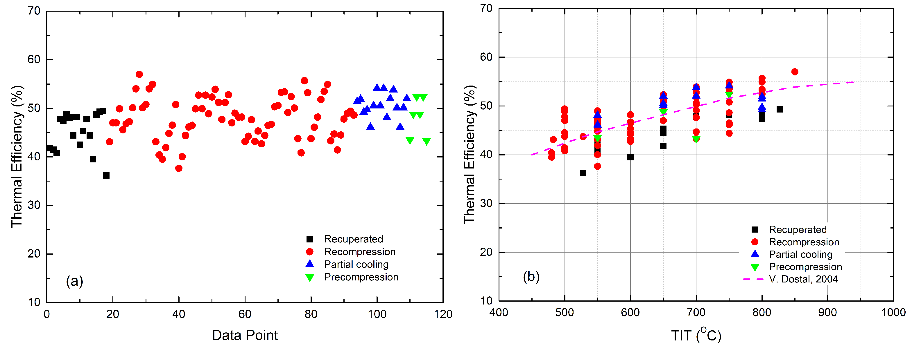
- The recompression sCO-ORC cycle achieves the highest overall efficiency. It can be seen from Figure 6 that most combined recompression cycles have efficiencies that are higher than the reference data at the same TITs, although the cycle boundary conditions are not identical.
- The distinct differences in the organic fluids show limited effects on the performance of the combined cycle. This is true, especially for large-scale sCO-ORC-combined cycles [50]. In the literature, both pure substances and zeotropic mixtures [43,59,60] were investigated. The nature of organic fluids decides the efficiency improvement that rises with TIT, like R245fa [42] and Isopentane [44], or falls, like the isobutane and the n-butane/isopentane mixture [43], as shown in Figure 7.
- For power generation, Yari and Sirousazar [41] first added a tCO cycle to the recompression sCO cycle, showing an efficiency improvement of around 5.1%. They also showed that the performance of the combined cycle was independent of TIT but was strongly affected by the ambient temperature. When increasing the ambient temperature from 15 °C to 25 °C, the gain in efficiency went down from 5.1% to 2.7%. Alsagri and Chiasson [58] reported that the recompression cycle using a split-flow tCO bottoming cycle obtained 2% more efficiency than that with a non-recuperated tCO cycle. As can be seen in Figure 7, the recuperated sCO cycle, for which the heat source is a molten carbonate fuel cell, was improved by 4.8–6.5% in terms of efficiency, depending on the recuperator effectiveness at a CIT of 55 °C [45,46]. When the CIT was lowered to 32 °C, the gain in efficiency for the tCO cycle was up to 7.2% [2].
- For cold production, Akbari and Mahmoudi [54] proposed a recompression sCO cycle combining a tCO refrigeration cycle for both power and refrigeration production. In the combined cycle, a fraction of CO leaving the cooler expends in the refrigeration cycle; after being heated and compressed, it then goes back to the cooler. They showed that the combined cycle produced 240 MW of power and 60 MW of cold simultaneously, or 562 MW of cold only. Manjunath et al. [61] studied a similar combined cycle utilizing the shipboard gas turbine exhaust. The proposed cycle generated a net power output of 3.0 MW (about 14.5% engine power) and a cooling output of 3.1 MW (about 15% engine power).
4. CO Mixture
- The available mixture database is required. The NIST REFPROP is currently used to calculate the thermophysical properties of a CO mixture. Experimental data are quite rare; only the properties of CO/xenon can be used so far [129]. However, the REFPROP program suggests the equation of state (EOS) temperature and pressure limits as follows: 161–750 K and 700 MPa for CO/Xe, 116–750 K and 200 MPa for CO/Kr, 188–760 K and 170 MPa for CO/HS, and 279–700 K and 80 MPa for CO/cyclohexane. In order to estimate the properties at higher temperatures, the temperature range of the REFPROP program has to be extended.
- The critical phenomena of CO mixtures should be considered carefully. The critical line has a continuous or discontinuous form among each critical point of the pure components. As for the discontinuous critical lines, the existence of phase separation could cause instability in the CO mixtures. This could hardly further obtain the optimum design of the compressor.
- The thermal stability of potential additives should be considered as a key selection criterion besides their thermodynamic performance. Otherwise, decomposition products, like non-condensable gases and deposits, may reduce the heat transfer rates, damage the components, and compromise cycle safety. Additional experiments are needed to identify the real phenomena of CO mixtures at high temperatures.
- The chemical effect on cycle components should be considered in the future.
5. Strengths and Weaknesses Analysis
6. Conclusions
Author Contributions
Funding
Data Availability Statement
Conflicts of Interest
Abbreviations
| sCO | supercritical carbon dioxide |
| tCO | transcritical carbon dioxide |
| TIT | turbine inlet temperature |
| TIP | turbine inlet pressure |
| CIT | compressor inlet temperature |
| CSP | concentrating solar power |
| WHR | waste heat recovery |
| ORC | organic Rankine cycle |
| TRC | transcritical Rankine cycle |
| EOS | equation of state |
| LNG | liquefied natural gas |
References
- Brun, K.; Friedman, P.; Dennis, R. Fundamentals and Applications of Supercritical Carbon Dioxide (sCO2) Based Power Cycles; Woodhead Publishing: Sawston, UK, 2017. [Google Scholar]
- Wang, X. A Supercritical CO2 Brayton Cycle Based Cogeneration System. Ph.D. Thesis, Xi’an Jiaotong University, Xi’an, China, 2018. (In Chinese). [Google Scholar]
- Tollefson, J. Innovative zero-emissions power plant begins battery of tests. Nature 2018, 557, 622–623. [Google Scholar] [CrossRef] [PubMed]
- Southwest Research Institute. SwRI, GTI and GE Break Ground on $119 Million Supercritical CO2 Pilot Power Plant. Available online: https://www.swri.org/press-release/swri-gti-ge-supercritical-CO2-pilot-power-plant (accessed on 18 September 2023).
- Benra, F.; Brillert, D.; Frybort, O.; Hajek, P.; Rohde, M.; Schuster, S.; Seewald, M.; Starflinger, J. A supercritical CO2 low temperature Brayton cycle for residual heat removal. In Proceedings of the 5th International Symposium—Supercritical CO2 Power Cycles, San Antonio, TX, USA, 28–31 March 2016. [Google Scholar]
- Institute of Engineering Thermophysics. China’s First Large-Scale Supercritical Carbon Dioxide Compressor Experimental Platform Completed and Put Into Operation. Available online: http://www.bjb.cas.cn/kjdt2016/201809/t201809295110326.html (accessed on 18 September 2023). (In Chinese).
- Institute of Engineering Thermophysics. Construction of a Comprehensive Test Platform for Full-Temperature Full-Pressure Supercritical Carbon Dioxide Heat Exchanger. Available online: http://www.dnl.ac.cn/info/1025/1167.htm (accessed on 18 September 2023). (In Chinese).
- Singh, R. Dynamics and Control of a Closed Carbon-Dioxide Brayton Cycle. Ph.D. Thesis, The University of Queensland, Brisbane, Australia, 2013. [Google Scholar]
- Dostal, V. A Supercritical Carbon Dioxide Cycle for Next Generation Nuclear Reactors. Ph.D. Thesis, Massachusetts Institute of Technology, Cambridge, MA, USA, 2004. [Google Scholar]
- Dyreby, J.J. Modeling the Supercritical Carbon Dioxide Brayton Cycle with Recompression. Ph.D. Thesis, University of Wisconsin-Madison, Madison, WI, USA, 2014. [Google Scholar]
- de la Calle, A.; Bayon, A.; Too, Y.C.S. Impact of ambient temperature on supercritical CO2 recompression Brayton cycle in arid locations: Finding the optimal design conditions. Energy 2018, 153, 1016–1027. [Google Scholar] [CrossRef]
- Moisseytsev, A.; Sienicki, J. Performance Improvement Options for the Supercritical Carbon Dioxide Brayton Cycle; Technical Report; ANL-GenIV-103; Argonne National Laboratory: Argonne, IL, USA, 2007. [Google Scholar]
- Ahn, Y.; Bae, S.J.; Kim, M.; Cho, S.K.; Baik, S.; Lee, J.I.; Cha, J.E. Review of supercritical CO2 power cycle technology and current status of research and development. Nucl. Eng. Technol. 2015, 47, 647–661. [Google Scholar] [CrossRef]
- Crespi, F.; Gavagnin, G.; Sánchez, D.; Martínez, G.S. Supercritical Carbon Dioxide Cycles for Power Generation: A Review. Appl. Energy 2017, 195, 152–183. [Google Scholar] [CrossRef]
- Li, M.; Zhu, H.; Guo, J.; Wang, K.; Tao, W. The development technology and applications of supercritical CO2 power cycle in nuclear energy, solar energy and other energy industries. Appl. Therm. Eng. 2017, 126, 255–275. [Google Scholar] [CrossRef]
- Wang, K.; He, Y.L.; Zhu, H.H. Integration between supercritical CO2 Brayton cycles and molten salt solar power towers: A review and a comprehensive comparison of different cycle layouts. Appl. Energy 2017, 195, 819–836. [Google Scholar] [CrossRef]
- Xu, J.; Liu, C.; Sun, E.; Xie, J.; Li, M.; Yang, Y.; Liu, J. Perspective of S-CO2 power cycles. Energy 2019, 186, 115831. [Google Scholar] [CrossRef]
- Jeong, W.S.; Jeong, Y.H. Performance of Supercritical Brayton Cycle Using CO2-based Binary Mixture at Varying Critical Points for SFR Applications. Nucl. Eng. Des. 2013, 262, 12–20. [Google Scholar] [CrossRef]
- Angelino, G. Real Gas Effects in Carbon Dioxide Cycles. In Proceedings of the ASME 1969 Gas Turbine Conference and Products Show, Cleveland, OH, USA, 10–13 March 1969. [Google Scholar]
- Kato, Y.; Nitawaki, T.; Muto, Y. Medium Temperature Carbon Dioxide Gas Turbine Reactor. Nucl. Eng. Des. 2004, 230, 195–207. [Google Scholar] [CrossRef]
- Ma, Y.; Liu, M.; Yan, J.; Liu, J. Thermodynamic Study of Main Compression Intercooling Effects on Supercritical CO2 Recompression Brayton Cycle. Energy 2017, 140, 746–756. [Google Scholar] [CrossRef]
- Couso, G.B.; Vicencio, R.B.; Padilla, R.V.; Too, Y.C.S.; Pye, J. Dynamic Model of Supercritical CO2 Brayton Cycles Driven by Concentrated Solar Power. In Proceedings of the ASME 2017 11th International Conference on Energy Sustainability, American Society of Mechanical Engineers, Charlotte, NC, USA, 26–30 June 2017; p. V001T05A008. [Google Scholar]
- Wang, X.; Wu, Y.; Wang, J.; Dai, Y.; Xie, D. Thermo-economic Analysis of A Recompression Supercritical CO2 Cycle Combined With A Transcritical CO2 Cycle. In Proceedings of the ASME Turbo Expo 2015: Turbine Technical Conference and Exposition, Montréal, QC, Canada, 15–19 June 2015. [Google Scholar]
- Stamatellos, G.; Stamatelos, T. Effect of actual recuperators effectiveness on the attainable efficiency of supercritical CO2 Brayton cycles for solar thermal power plants. Energies 2022, 15, 7773. [Google Scholar] [CrossRef]
- Ren, Z.; Zhao, C.R.; Jiang, P.X.; Bo, H.L. Investigation on local convection heat transfer of supercritical CO2 during cooling in horizontal semicircular channels of printed circuit heat exchanger. Appl. Therm. Eng. 2019, 157, 113697. [Google Scholar] [CrossRef]
- Stamatellos, G.; Stamatellou, A.; Kalfas, A.I. CFD—Aided design methodology for PCHE-type recuperators in supercritical CO2 recompression power cycles. In Proceedings of the ASME Turbo Expo 2020: Turbomachinery Technical Conference and Exposition, New York, NY, USA, 21–25 September 2020. [Google Scholar]
- Dostal, V.; Driscoll, M.J.; Hejzlar, P.; Todreas, N.E. A Supercritical CO2 Gas Turbine Power Cycle for Next-generation Nuclear Reactors. In Proceedings of the 10th International Conference on Nuclear Engineering, Arlington, VA, USA, 14–18 April 2002. [Google Scholar]
- Sarkar, J.; Bhattacharyya, S. Optimization of Recompression S-CO2 Power Cycle With Reheating. Energy Convers. Manag. 2009, 50, 1939–1945. [Google Scholar] [CrossRef]
- Kulhanek, M.; Dostal, V. Thermodynamic Analysis and Comparison of Supercritical Carbon Dioxide Cycles. In Proceedings of the Supercritical CO2 Power Cycle Symposium, Boulder, CO, USA, 24–25 May 2011. [Google Scholar]
- Turchi, C.S.; Ma, Z.; Neises, T.; Wagner, M. Thermodynamic Study of Advanced Supercritical Carbon Dioxide Power Cycles for High Performance Concentrating Solar Power Systems. In Proceedings of the ASME 2012 6th International Conference on Energy Sustainability, San Diego, CA, USA, 23–26 July 2012. [Google Scholar]
- Turchi, C.S.; Ma, Z.; Dyreby, J. Supercritical Carbon Dioxide Power Cycle Configuration for Use in Concentrating Solar Power Systems. In Proceedings of the ASME Turbo Expo 2012: Turbine Technical Conference and Exposition, American Society of Mechanical Engineers, Copenhagen, Denmark, 11–15 June 2012; pp. 967–973. [Google Scholar]
- Padilla, R.V.; Benito, R.G.; Stein, W. An Exergy Analysis of Recompression Supercritical CO2 Cycles With and Without Reheating. Energy Procedia 2015, 69, 1181–1191. [Google Scholar] [CrossRef]
- Padilla, R.V.; Too, Y.C.S.; Beath, A.; McNaughton, R.; Stein, W. Effect of Pressure Drop and Reheating on Thermal and Exergetic Performance of Supercritical Carbon Dioxide Brayton Cycles Integrated With a Solar Central Receiver. J. Sol. Energy Eng. 2015, 137, 051012. [Google Scholar] [CrossRef]
- Mounir Mecheri, Y.L.M. Supercritical CO2 Brayton Cycles for Coal-fired Power Plants. Energy 2016, 103, 758–771. [Google Scholar] [CrossRef]
- Purjam, M.; Goudarzi, K.; Keshtgar, M. A New Supercritical Carbon Dioxide Brayton Cycle with High Efficiency. Heat Transf.—Asian Res. 2017, 46, 465–482. [Google Scholar] [CrossRef]
- Coco-Enriquez, L.; Munoz-Anton, J.; Martinez-Val, J. Thermodynamic Optimization of Supercritical CO2 Brayton Power Cycles Coupled to Line-Focusing Solar Fields. J. Sol. Energy Eng. 2017, 139, 061005. [Google Scholar] [CrossRef]
- Binotti, M.; Astolfi, M.; Campanari, S.; Manzolini, G.; Silva, P. Preliminary Assessment of sCO2 Cycles for Power Generation in CSP Solar Tower Plants. Appl. Energy 2017, 204, 1007–1017. [Google Scholar] [CrossRef]
- Coco-Enriquez, L.; Munoz-Anton, J.; Martinez-Val, J. Dual Loop Line-Focusing Solar Power Plants With Supercritical Brayton Power Cycles. Int. J. Hydrogen Energy 2017, 42, 17664–17680. [Google Scholar] [CrossRef]
- Moisseytsev, A. Passive Load Follow Analysis of the STAR-LM and STAR-H2 Systems. Ph.D. Thesis, Texas A&M University, College Station, TX, USA, 2003. [Google Scholar]
- Angelino, G. Carbon Dioxide Condensation Cycles for Power Production. J. Eng. Power Trans. ASME 1968, 90, 287–295. [Google Scholar] [CrossRef]
- Yari, M.; Sirousazar, M. A Novel Recompression S-CO2 Brayton Cycle With Pre-cooler Exergy Utilization. Proc. Inst. Mech. Eng. Part A J. Power Energy 2010, 224, 931–946. [Google Scholar] [CrossRef]
- Chacartegui, R.; de Escalona, J.M.; Sánchez, D.; Monje, B.; Sánchez, T. Alternative Cycles Based on Carbon Dioxide for Central Receiver Solar Power Plants. Appl. Therm. Eng. 2011, 31, 872–879. [Google Scholar] [CrossRef]
- Sánchez, D.; Brenes, B.M.; de Escalona, J.M.M.; Chacartegui, R. Non-conventional Combined Cycle for Intermediate Temperature Systems. Int. J. Energy Res. 2013, 37, 403–411. [Google Scholar] [CrossRef]
- Besarati, S.M.; Goswami, D.Y. Analysis of Advanced Supercritical Carbon Dioxide Power Cycles With a Bottoming Cycle for Concentrating Solar Power Applications. J. Sol. Energy Eng. 2014, 136, 010904. [Google Scholar] [CrossRef]
- Bae, S.J.; Ahn, Y.; Lee, J.; Lee, J.I. Hybrid System of Supercritical Carbon Dioxide Brayton Cycle and Carbon Dioxide Rankine Cycle Combined Fuel Cell. In Proceedings of the ASME Turbo Expo, Düsseldorf, Germany, 16–20 June 2014. [Google Scholar]
- Bae, S.J.; Ahn, Y.; Lee, J.; Lee, J.I. Various Supercritical Carbon Dioxide Cycle Layouts Study for Molten Carbonate Fuel Cell Application. J. Power Sources 2014, 270, 608–618. [Google Scholar] [CrossRef]
- Zhang, H.; Shao, S.; Zhao, H.; Feng, Z. Thermodynamic Analysis of a SCO2 Part-Flow Cycle Combined With an Organic Rankine Cycle With Liquefied Natural Gas as Heat Sink. In Proceedings of the ASME Turbo Expo 2014: Turbine Technical Conference and Exposition, American Society of Mechanical Engineers, Düsseldorf, Germany, 16–20 June 2014; p. V03BT36A012. [Google Scholar]
- Akbari, A.D.; Mahmoudi, S.M. Thermoeconomic Analysis & Optimization of the Combined Supercritical CO2 (Carbon Dioxide) Recompression Brayton/Organic Rankine Cycle. Energy 2014, 78, 501–512. [Google Scholar]
- Wang, X.; Wang, J.; Zhao, P.; Dai, Y. Thermodynamic comparison and optimization of supercritical CO2 Brayton cycles with a bottoming transcritical CO2 cycle. J. Energy Eng. 2015, 142, 04015028. [Google Scholar] [CrossRef]
- Wang, X.; Dai, Y. Exergoeconomic Analysis of Utilizing the Transcritical CO2 Cycle and the ORC for A Recompression Supercritical CO2 Cycle Waste Heat Recovery: A Comparative Study. Appl. Energy 2016, 170, 193–207. [Google Scholar] [CrossRef]
- S Mahmoudi, S.M.; D Akbari, A.; Rosen, M.A. Thermoeconomic Analysis and Optimization of A New Combined Supercritical Carbon Dioxide Recompression Brayton/Kalina cycle. Sustainability 2016, 8, 1079. [Google Scholar] [CrossRef]
- Li, H.; Wang, M.; Wang, J.; Dai, Y. Exergoeconomic Analysis and Optimization of A Supercritical CO2 Cycle Coupled With A Kalina Cycle. J. Energy Eng. 2016, 143, 04016055. [Google Scholar] [CrossRef]
- Mahmoudi, S.; Ghavimi, A. Thermoeconomic analysis and multi objective optimization of a molten carbonate fuel cell—Supercritical carbon dioxide—Organic Rankin cycle integrated power system using liquefied natural gas as heat sink. Appl. Therm. Eng. 2016, 107, 1219–1232. [Google Scholar] [CrossRef]
- Akbari, A.; Mahmoudi, S. Thermoeconomic Performance and Optimization of A Novel Cogeneration System Using Carbon Dioxide as Working Fluid. Energy Convers. Manag. 2017, 145, 265–277. [Google Scholar] [CrossRef]
- Cao, Y.; Ren, J.; Sang, Y.; Dai, Y. Thermodynamic analysis and optimization of a gas turbine and cascade CO2 combined cycle. Energy Convers. Manag. 2017, 144, 193–204. [Google Scholar] [CrossRef]
- Hou, S.; Wu, Y.; Zhou, Y.; Yu, L. Performance analysis of the combined supercritical CO2 recompression and regenerative cycle used in waste heat recovery of marine gas turbine. Energy Convers. Manag. 2017, 151, 73–85. [Google Scholar] [CrossRef]
- Wang, X.; Yang, Y.; Zheng, Y.; Dai, Y. Exergy and exergoeconomic analyses of a supercritical CO2 cycle for a cogeneration application. Energy 2017, 119, 971–982. [Google Scholar] [CrossRef]
- Alsagri, A.S.; Chiasson, A.D. Thermodynamic Analysis and Multi-Objective Optimizations of a Combined Recompression SCO2 Brayton Cycle-TCO2 Rankine Cycles for Waste Heat Recovery. Int. J. Curr. Eng. Technol. 2018, 8, 541–548. [Google Scholar]
- Hou, S.; Cao, S.; Yu, L.; Zhou, Y.; Wu, Y.; Zhang, F. Performance Optimization of Combined Supercritical CO2 Recompression Cycle and Regenerative Organic Rankine Cycle Using Zeotropic Mixture Fluid. Energy Convers. Manag. 2018, 166, 187–200. [Google Scholar] [CrossRef]
- Hou, S.; Zhou, Y.; Yu, L.; Zhang, F.; Cao, S.; Wu, Y. Optimization of A Novel Cogeneration System Including A Gas Turbine, A Supercritical CO2 Recompression Cycle, A Steam Power Cycle and An Organic Rankine Cycle. Energy Convers. Manag. 2018, 172, 457–471. [Google Scholar] [CrossRef]
- Manjunath, K.; Sharma, O.; Tyagi, S.; Kaushik, S. Thermodynamic Analysis of A Supercritical/transcritical CO2 Based Waste Heat Recovery Cycle for Shipboard Power and Cooling Applications. Energy Convers. Manag. 2018, 155, 262–275. [Google Scholar] [CrossRef]
- Singh, H.; Mishra, R. Performance Analysis of Solar Parabolic Trough Collectors Driven Combined Supercritical CO2 and Organic Rankine Cycle. Eng. Sci. Technol. Int. J. 2018, 21, 451–464. [Google Scholar]
- Song, J.; song Li, X.; dong Ren, X.; wei Gu, C. Performance Analysis and Parametric Optimization of Supercritical Carbon Dioxide (S-CO2) Cycle With Bottoming Organic Rankine Cycle (ORC). Energy 2018, 143, 406–416. [Google Scholar] [CrossRef]
- Cao, Y.; Rattner, A.S.; Dai, Y. Thermoeconomic analysis of a gas turbine and cascaded CO2 combined cycle using thermal oil as an intermediate heat-transfer fluid. Energy 2018, 162, 1253–1268. [Google Scholar] [CrossRef]
- Dipippo, R. Geothermal Power Plants. Principles Applications, and Case Studies; Elsevier Science: Amsterdam, The Netherlands, 2005. [Google Scholar]
- Harinck, J.; Turunen-Saaresti, T.; Colonna, P.; Rebay, S.; van Buijtenen, J. Computational Study of A High Expansion Ratio Radial Organic Rankine Cycle Turbine Stator. J. Eng. Gas Turbines Power 1996, 118, 359–367. [Google Scholar] [CrossRef]
- Drescher, U.; Bruggemann, D. Fluid Selection for the Organic Rankine Cycle (ORC) in Biomass Power and Heat Plants. Appl. Therm. Eng. 2007, 27, 223–228. [Google Scholar] [CrossRef]
- Lai, N.A.; Wendland, M.; Fischer, J. Working Fluids for High-Temperature Organic Rankine Cycles. Energy 2011, 36, 199–211. [Google Scholar] [CrossRef]
- Quoilin, S.; Aumann, R.; Grill, A.; Schuster, A.; Lemort, V.; Spliethoff, H. Dynamic Modeling and Optimal Control Strategy of Waste Heat Recovery Organic Rankine Cycles. Appl. Energy 2011, 88, 2183–2190. [Google Scholar] [CrossRef]
- Chacartegui, R.; Sánchez, D.; Jiménez-Espadafor, F.; Muñoz, A.; Sánchez, T. Analysis of Intermediate Temperature Combined Cycles With A Carbon Dioxide Topping Cycle. In Proceedings of the ASME Turbo Expo 2008: Power for Land, Sea and Air, Berlin, Germany, 9–13 June 2008; pp. 673–680. [Google Scholar]
- El-Genk, M.; Tournier, J. Noble Gas Mixtures for Gas-cooled Reactor Power Plants. Nucl. Eng. Des. 2008, 238, 1353–1372. [Google Scholar] [CrossRef]
- El-Genk, M.; Tournier, J. Performance Analyses of VHTR Plants With Direct and Indirect Closed Brayton Cycles and Different Working Fluids. Prog. Nucl. Energy 2009, 51, 556–572. [Google Scholar] [CrossRef]
- Wang, X.; Zhao, L. Analysis of zeotropic mixtures used in low-temperature solar Rankine cycles for power generation. Sol. Energy 2009, 83, 605–613. [Google Scholar] [CrossRef]
- Bao, J.; Zhao, L. A review of working fluid and expander selections for organic Rankine cycle. Renew. Sustain. Energy Rev. 2013, 24, 325–342. [Google Scholar] [CrossRef]
- Feng, Y.; Hung, T.; Zhang, Y.; Li, B.; Yang, J.; Shi, Y. Performance comparison of low-grade ORCs (organic Rankine cycles) using R245fa, pentane and their mixtures based on the thermoeconomic multi-objective optimization and decision makings. Energy 2015, 93, 2018–2029. [Google Scholar] [CrossRef]
- Sadeghi, M.; Nemati, A.; ghavimi, A.; Yari, M. Thermodynamic analysis and multi-objective optimization of various ORC (organic Rankine cycle) configurations using zeotropic mixtures. Energy 2016, 109, 791–802. [Google Scholar] [CrossRef]
- Modi, A.; Haglind, F. A review of recent research on the use of zeotropic mixtures in power generation systems. Energy Convers. Manag. 2017, 138, 603–626. [Google Scholar] [CrossRef]
- Dai, B.; Dang, C.; Li, M.; Tian, H.; Ma, Y. Thermodynamic performance assessment of carbon dioxide blends with low-global warming potential (GWP) working fluids for a heat pump water heater. Int. J. Refrig. 2015, 56, 1192145. [Google Scholar] [CrossRef]
- Wang, D.; Lu, Y.; Tao, L. Thermodynamic analysis of CO2 blends with R41 as an azeotropy refrigerant applied in small refrigerated cabinet and heat pump water heater. Appl. Therm. Eng. 2017, 125, 1490–1500. [Google Scholar] [CrossRef]
- Hu, J.; Liu, C.; Li, Q.; Shi, X. Molecular simulation of thermal energy storage of mixed CO2/IRMOF-1 nanoparticle nanofluid. Int. J. Heat Mass Transf. 2018, 125, 1345–1348. [Google Scholar] [CrossRef]
- Dai, B.; Li, M.; Ma, Y. Thermodynamic analysis of carbon dioxide blends with low GWP (global warming potential) working fluids-based transcritical Rankine cycles for low-grade heat energy recovery. Energy 2014, 64, 942–952. [Google Scholar] [CrossRef]
- Yang, M.H. The performance analysis of the transcritical Rankine cycle using carbon dioxide mixtures as the working fluids for waste heat recovery. Energy Convers. Manag. 2017, 151, 86–97. [Google Scholar] [CrossRef]
- Shu, G.; Yu, Z.; Tian, H.; Liu, P.; Xu, Z. Potential of the transcritical Rankine cycle using CO2-based binary zeotropic mixtures for engine’s waste heat recovery. Energy Convers. Manag. 2018, 174, 668–685. [Google Scholar] [CrossRef]
- Sánchez, C.J.; da Silva, A.K. Technical and environmental analysis of transcritical Rankine cycles operating with numerous CO2 mixtures. Energy 2018, 142, 180–190. [Google Scholar] [CrossRef]
- Lewis, T.; Wright, S.; Conboy, T. Supercritical CO2 Mixture Behavior for Advanced Power Cycles and Applications. In Proceedings of the Supercritical CO2 Power Cycle Symposium, Boulder, CO, USA, 24–25 May 2011. [Google Scholar]
- Jeong, W.S.; Jeong, Y.H.; Lee, J.I. Performance of S-CO2 Brayton Cycle with Additive Gases for SFR Application. In Proceedings of the Supercritical CO2 Power Cycle Symposium, Boulder, CO, USA, 24–25 May 2011. [Google Scholar]
- Jeong, W.S.; Lee, J.I.; Jeong, Y.H. Potential Improvements of Supercritical Recompression CO2 Brayton Cycle by Mixing Other Gases for Power Conversion System of A SFR. Nucl. Eng. Des. 2011, 241, 2128–2137. [Google Scholar] [CrossRef]
- Baik, S.; Lee, J.I. Preliminary Study of Supercritical CO2 Mixed With Gases for Power Cycle in Warm Environments. In Proceedings of the ASME Turbo Expo 2018: Turbomachinery Technical Conference and Exposition, Oslo, Norway, 11–15 June 2018; p. V009T38A017. [Google Scholar]
- Vesely, L.; Dostal, V.; Stepanek, J. Effect of Gaseous Admixtures on Cycles with Supercritical Carbon Dioxide. In Proceedings of the ASME Turbo Expo 2016: Turbomachinery Technical Conference and Exposition, GT2016, Seoul, Republic of Korea, 13–17 June 2016. [Google Scholar]
- Vesely, L.; Dostal, V. Effect of Multicomponent Mixtures on Cycles with Supercritical Carbon Dioxide. In Proceedings of the ASME Turbo Expo 2017: Turbomachinery Technical Conference and Exposition, GT2017, Charlotte, NC, USA, 26–30 June 2017. [Google Scholar]
- Vesely, L.; Manikantachari, K.R.V.; Vasu, S.; Kapat, J.; Dostal, V.; Martin, S. Effect of Mixtures on Compressor and Cooler in Supercritical Carbon Dioxide Cycles. In Proceedings of the ASME Turbo Expo 2018: Turbomachinery Technical Conference and Exposition, GT2018, Oslo, Norway, 11–15 June 2018. [Google Scholar]
- Jeong, W.S.; Lee, J.I.; Jeong, Y.H.; NO, H.C. Potential Improvements of Supercritical Recompression CO2 Brayton Cycle Coupled with KALIMER-600 by Modifying Critical Point of CO2. In Proceedings of the Transactions of the Korean Nuclear Society Autumn Meeting, Jeju, Republic of Korea, 21–22 October 2010. [Google Scholar]
- Invernizzi, C.M.; van der Stelt, T. Supercritical and real gas Brayton cycles operating with mixtures of carbon dioxide and hydrocarbons. Proc. Inst. Mech. Eng. Part A J. Power Energy 2012, 226, 682–693. [Google Scholar] [CrossRef]
- Vesely, L.; Dostal, V. Research on the Effect of the Pinch Point Shift in Cycles with Supercritical Carbon Dioxide. In Proceedings of the 4th International Symposium—Supercritical CO2 Power Cycles, Pittsburgh, PA, USA, 9–10 September 2014. [Google Scholar]
- Hu, L.; Chen, D.; Huang, Y.; Li, L.; Cao, Y.; Yuan, D.; Wang, J.; Pan, L. Investigation on the Performance of the Supercritical Brayton Cycle With CO2-based Binary Mixture as Working Fluid for An Energy Transportation System of A Nuclear Reactor. Energy 2015, 89, 874–886. [Google Scholar] [CrossRef]
- Bonalumi, D.; Lasala, S.; Macchi, E. CO2-TiCl4 working fluid for high-temperature heat source power cycles and solar application. Renew. Energy 2020, 147, 2842–2854. [Google Scholar] [CrossRef]
- Binotti, M.; Invernizzi, C.M.; Iora, P.; Manzolini, G. Dinitrogen tetroxide and carbon dioxide mixtures as working fluids in solar tower plants. Sol. Energy 2019, 181, 203–213. [Google Scholar] [CrossRef]
- Manzolini, G.; Binotti, M.; Bonalumi, D.; Invernizzi, C.; Iora, P. CO2 mixtures as innovative working fluid in power cycles applied to solar plants. Techno-economic assessment. Sol. Energy 2019, 181, 530–544. [Google Scholar] [CrossRef]
- Guo, J.Q.; Li, M.J.; Xu, J.L.; Yan, J.J.; Wang, K. Thermodynamic performance analysis of different supercritical Brayton cycles using CO2-based binary mixtures in the molten salt solar power tower systems. Energy 2019, 173, 785–798. [Google Scholar] [CrossRef]
- Yin, H.; Sabau, A.S.; Conklin, J.C.; McFarlane, J.; Qualls, A.L. Mixtures of SF6-CO2 as working fluids for geothermal power plants. Appl. Energy 2013, 106, 243–253. [Google Scholar] [CrossRef]
- Wu, C.; sen Wang, S.; Jiang, X.; Li, J. Thermodynamic analysis and performance optimization of transcritical power cycles using CO2-based binary zeotropic mixtures as working fluids for geothermal power plants. Appl. Therm. Eng. 2017, 115, 292–304. [Google Scholar] [CrossRef]
- Feng, L.; Zheng, D.; Chen, J.; Dai, X.; Shi, L. Exploration and Analysis of CO2 + Hydrocarbons Mixtures as Working Fluids for Trans-critical ORC. Energy Procedia 2017, 129, 145–151. [Google Scholar] [CrossRef]
- Zabetakis, M.G. Flammability Characteristics of Combustible Gases and Vapors; Technical Report; Bureau of Mines: Washington, DC, USA, 1965.
- Badr, O.; Probert, S.; O’Callaghan, P. Selecting a working fluid for a Rankine-cycle engine. Appl. Energy 1985, 21, 1–42. [Google Scholar] [CrossRef]
- Ginosar, D.M.; Petkovic, L.M.; Guillen, D.P. Thermal Stability of Cyclopentane as an Organic Rankine Cycle Working Fluid. Energy Fuels 2011, 25, 4138–4144. [Google Scholar] [CrossRef]
- Dai, X.; An, Q.; Shi, L. Experiment research for the thermal stability of isobutene and isopentane. J. Eng. Thermophys. 2013, 34, 1416–1419. (In Chinese) [Google Scholar]
- Barin, I.; Knacke, O. Thermochemical Properties of Inorganic Substances; Springer Berlin: Heidelberg, Germany, 1973. [Google Scholar]
- Fukuda, K.; Dokiya, M.; Kameyama, T.; Kotera, Y. Catalytic decomposition of hydrogen sulfide. Ind. Eng. Chem. Fundam. 1978, 17, 243–248. [Google Scholar] [CrossRef]
- Chivers, T.; Hyne, J.B.; Lau, C. The thermal decomposition of hydrogen sulfide over transition metal sulfides. Int. J. Hydrogen Energy 1980, 5, 499–506. [Google Scholar] [CrossRef]
- Weil, E.D.; Sandler, S.R.; Gernon, M. Kirk-Othmer Encyclopedia of Chemical Technology; John Wiley & Sons, Inc.: New York, NY, USA, 2006; Chapter Sulfur Compounds. [Google Scholar]
- Devarakonda, A.; Olminsky, J. An evaluation of halides and other substances as potential heat pipe fluids. In Proceedings of the 2nd International Energy Conversion Engineering Conference, Providence, RI, USA, 16–19 August 2004; p. 5575. [Google Scholar]
- Devarakonda, A.; Anderson, W.G. Thermo-Physical Properties of Intermediate Temperature Heat Pipe Fluids. AIP Conf. Proc. 2005, 746, 179–186. [Google Scholar]
- Invernizzi, C.; Iora, P.; Bonalumi, D.; Macchi, E.; Roberto, R.; Caldera, M. Titanium tetrachloride as novel working fluid for high temperature Rankine Cycles: Thermodynamic analysis and experimental assessment of the thermal stability. Appl. Therm. Eng. 2016, 107, 21–27. [Google Scholar] [CrossRef]
- Bombarda, P.; Invernizzi, C. Binary liquid metal-organic Rankine cycle for small power distributed high efficiency systems. Proc. Inst. Mech. Eng. Part A J. Power Energy 2015, 229, 192–209. [Google Scholar] [CrossRef]
- Krasin, A.; Nesterenko, V. Dissociating Gases: A New Class of Coolants and Working Substances for Large Power Plants. At. Energy Rev. 1971, 9, 177–194. [Google Scholar]
- Lemmon, E.W.; Bell, I.; Huber, M.L.; McLinden, M.O. NIST Standard Reference Database 23: Reference Fluid Thermodynamic and Transport Properties-REFPROP; Version 10.0; National Institute of Standards and Technology: Gaithersburg, MD, USA, 2018.
- Solovyev, E.; Kuvshinov, D.; Ermakov, D.; Kuvshinov, G. Production of hydrogen and nanofibrous carbon by selective catalytic decomposition of propane. Int. J. Hydrogen Energy 2009, 34, 1310–1323. [Google Scholar] [CrossRef]
- Dai, X.; Shi, L.; An, Q.; Qian, W. Screening of hydrocarbons as supercritical ORCs working fluids by thermal stability. Energy Convers. Manag. 2016, 126, 632–637. [Google Scholar] [CrossRef]
- Tsang, W. Thermal stability of cyclohexane and 1-hexene. Int. J. Chem. Kinet. 1978, 10, 1119–1138. [Google Scholar] [CrossRef]
- Zanetti, J.; Egloff, G. The Thermal Decomposition of Benzene. Ind. Eng. Chem. 1917, 9, 350–356. [Google Scholar] [CrossRef]
- Invernizzi, C.M.; Iora, P.; Manzolini, G.; Lasala, S. Thermal stability of n-pentane, cyclo-pentane and toluene as working fluids in organic Rankine engines. Appl. Therm. Eng. 2017, 121, 172–179. [Google Scholar] [CrossRef]
- Invernizzi, C.; Bonalumi, D. Thermal stability of organic fluids for Organic Rankine Cycle systems. In Organic Rankine Cycle (ORC) Power Systems; Macchi, E., Astolfi, M., Eds.; Woodhead Publishing: Sawston, UK, 2017; pp. 121–151. [Google Scholar]
- Dai, X.; Shi, L.; An, Q.; Qian, W. Thermal stability of some hydrofluorocarbons as supercritical ORCs working fluids. Appl. Therm. Eng. 2018, 128, 1095–1101. [Google Scholar] [CrossRef]
- Calderazzi, L.; di Paliano, P.C. Thermal stability of R-134a, R-141b, R-13I1, R-7146, R-125 associated with stainless steel as a containing material. Int. J. Refrig. 1997, 20, 381–389. [Google Scholar] [CrossRef]
- Angelino, G.; Invernizzi, C. Experimental investigation on the thermal stability of some new zero ODP refrigerants. Int. J. Refrig. 2003, 26, 51–58. [Google Scholar] [CrossRef]
- Okada, K.; Tschuikow-Roux, E.; Evans, P. Single-pulse shock-tube study of the thermal decomposition of ethyl fluoride and propyl chloride. J. Phys. Chem. 1980, 84, 467–471. [Google Scholar] [CrossRef]
- Ito, M.; Dang, C.; Hihara, E. Thermal decomposition of lower-GWP refrigerants. In Proceedings of the 15th International Refrigeration and Air Conditioning Conference at Purdue, Purdue University, West Lafayette, IN, USA, 14–17 July 2014. [Google Scholar]
- Lees, F.P. Loss Prevention in the Process Industries: Hazard Identification, Assessment, and Control; Butterworth-Heinemann: Oxford, UK, 1996; Volume 1. [Google Scholar]
- Ribeiro, N.; Casimiro, T.; Duarte, C.; Nunes da Ponte, M.; Aguiar-Ricardo, A.; Poliakoff, M. Vapor- Liquid Equilibrium and Critical Line of the CO2+ Xe System. Critical Behavior of CO2+ Xe versus CO2+ n-Alkanes. J. Phys. Chem. B 2000, 104, 791–795. [Google Scholar] [CrossRef]


| Cycle Layout | Initial Behavior | Improved Behavior | Application | Ref. | ||||
|---|---|---|---|---|---|---|---|---|
| CIT/°C | TIP/MPa | TIT/°C | /% | Method | /% | |||
| Intercooled Recuperated | 31 | 22 | 550 | 39 | Recompression, Increase TIT | 41.8–47 | 300 MWe Nuclear power | 2002 [27] |
| Recompression | 31 | 20 | 550 | 43.1, 45.8 | Increase TIT | 47, 49.9 | 600 MWth Nuclear power | 2002 [27] |
| Recuperated | 32 | 20 | 550 | 40 | Reheating, Intercooling | 40.8–41.5 | 600 MWth Nuclear power | 2004 [9] |
| Recompression | 32 | 20 | 550–750 | 45.56–52 | Reheating, Increase TIT, Raise TIP | 46.775–57 | 600 MWth Nuclear power | 2004 [9] |
| Recuperated | 35 | 7, 12 | 800 | 45.5, 45.8 | Intercooling, Partial cooling | 47.4–49.7 | Nuclear power | 2004 [20] |
| Partial cooling | 35 | 7, 12 | 800 | 49.2, 49.7 | Intercooling | 51.4, 51.9 | Nuclear power | 2004 [20] |
| Recompression | 31.25 | 20 | 472 | 39.1 | Condensation, Liquid phase pumping, Raise TIP | 39.5–43.1 | 250 MWth Nuclear power | 2007 [12] |
| Recompression | 32, 50 | 20, 30 | 550, 750 | 36.71–49.83 | Reheating | 37.65–50.78 | 600 MWth Nuclear power | 2009 [28] |
| Recuperated | 32 | 25 | 550–750 | 40.44–48.2 | Precompression, Recompression, Partial cooling, Increase TIT | 43.49–54.1 | 3600 MWth Nuclear power | 2011 [29] |
| Precompression | 32 | 25 | 550 | 43.49 | Increase TIT | 48.8, 52.4 | 3600 MWth Nuclear power | 2011 [29] |
| Recompression | 32 | 25 | 550 | 46.48 | Increase TIT | 49.9, 52.7 | 3600 MWth Nuclear power | 2011 [29] |
| Partial cooling | 32 | 25 | 550 | 46.12 | Increase TIT | 50.5, 54.1 | 3600 MWth Nuclear power | 2011 [29] |
| Recuperated | 32 | 25 | 550–700 | 40.7–45.5 | Reheating, Increase TIT, Recompression, Partial cooling | 42.5–52.8 | CSP | 2012 [30] |
| Recompression | 32 | 25 | 550–700 | 47.7–52.8 | Reheating, Increase TIT | 48.9–53.9 | CSP | 2012 [30] |
| Partial cooling | 32 | 25 | 550–700 | 46.1–52 | Reheating, Increase TIT | 48.1–53.8 | CSP | 2012 [30] |
| Recompression | 32 | 25 | 500–600 | 44.5–46 | Reheating, Increase TIT | 47–49 | 10 MWe CSP | 2012 [31] |
| Recompression | 55.5 | 25 | 500–850 | 40–52 | Reheating, Increase TIT | 43.14–52.8 | CSP | 2015 [32] |
| Recuperated | 55.5 | 25 | 600 | 38.5 | Reheating, Recompression | 39.5, 42.7 | CSP | 2015 [33] |
| Recompression | 55.5 | 25 | 600 | 42.7 | Reheating, Intercooling | 43.2–45.3 | CSP | 2015 [33] |
| Recompression | 32 | 25 | 600–800 | 45.1–52.4 | Reheating, Increase TIT | 46.5–53.4 | 2113 MWth Fossil energy | 2016 [34] |
| Recompression | 35, 50 | 20 | 500–800 | 39.59–54.58 | Intercooling | 40.82–55.68 | Nuclear power | 2017 [21] |
| Recuperated with reheating | 27 | 25 | 827 | 46.3 | Intercooling | 48.7–49.4 | 160 MWe Not specified | 2017 [35] |
| Recuperated | - | 25 | 700 | 36.2 | Recompression, Precompression | 43.3 | 104 MWe CSP | 2017 [22] |
| Recompression with reheating | 32 | 25 | 500 | 40.98–49.21 | Intercooling | 41.44–49.4 | 50 MWe CSP | 2017 [36] |
| Recompression | 51 | 25 | 750 | 47 | Intercooling | 48.6 | 25 MWe CSP | 2017 [37] |
| Cycle Layout | Initial Behavior | Improved Behavior | Application | Ref. | ||||||
|---|---|---|---|---|---|---|---|---|---|---|
| CIT/°C | TIP/MPa | TIT/°C | /% | Cost | Bottoming Cycle | /% | Cost | |||
| Recompression | 32 | 22.3 | 550–750 | 40.23–47.82 | - | tCO cycle | 44.25–52.98 | - | 90–165 kWe nuclear power | 2010 [41] |
| Recuperated | 35 | 22.5 | 527–727 | 28.5–33.8 | - | ORC (R245fa, isobutane, isopentane, cyclohexane) | 36.4–43.96 | - | 88–115 kWe CSP | 2011 [42] |
| Recuperated | 30 | - | 527–827 | 28.1–38.7 | - | ORC (isopentane, isobutane, n-Butane) | 35.3–47.5 | - | 500 kWe CSP | 2013 [43] |
| Recuperated | 55 | 25 | 700–850 | 41.9–46.5 | - | ORC (isopentane, n-butene, cis-butene) | 48–53 | - | CSP | 2014 [44] |
| Recompression | 55 | 25 | 700-850 | 46.3–50.6 | - | ORC (R236ea, R245fa, isobutane) | 50.5–55.75 | - | CSP | 2014 [44] |
| Partial cooling | 55 | 25 | 700–850 | 46.2–51 | - | ORC (R124, R245fa, isobutane) | 48.7–53.95 | - | CSP | 2014 [44] |
| Recuperated | 35 | 22.5 | 650 | 33.8, 36.5 | - | tCO cycle | 39.5, 41.3 | - | 326 kWth Fuel cell | 2014 [45] |
| Recuperated | 35 | 22.5 | 650 | 39.6 | - | tCO cycle | 46.1 | - | 326 kWth Fuel cell | 2014 [46] |
| Recompression | 35 | 20 | 527 | 45.32 | - | ORC (R123) | 52.12 | - | 570 kWth Nuclear power | 2014 [47] |
| Recompression | 35 | 22.2 | 550 | 39.59, 38.3 | 11.2 $/GJ, 10.87 $/GJ | ORC (Isopentane, n-butane, isobutane, n-pentane, R123, R114, R141b, RC318) | 43.68–44.22 | 10.73 $/GJ, 10.25 $/GJ | 600 MWth Nuclear power | 2014 [48] |
| Recompression | 32 | 20 | 550 | 44.29 | 6.2 $/kW | tCO cycle | 45.92 | 6.6 $/kW | 84 kWe Nuclear power | 2015 [23] |
| Recuperated | 32 | 20 | 550 | 37.46 | - | tCO cycle | 44.7 | - | 96 kWe Nuclear power | 2015 [49] |
| Recompression | 32 | 20 | 550 | 44.22 | - | tCO cycle | 47.69 | - | 81 kWe Nuclear power | 2015 [49] |
| Recompression | 32 | 26.7, 21 | 550 | - | - | tCO cycle | 44.99, 43.89 | 9.98 $/GJ, 9.75 $/GJ | 600 MWth Nuclear power | 2016 [50] |
| Recompression | 32 | 28.12–29.53, 20.87–21.16 | 550 | - | - | ORC (R123, R245fa, toluene, isobutane, isopentane, cyclohexane) | 44.77–45.23, 43.78–44.08 | 9.88–9.96 $/GJ, 9.60–9.62 $/GJ | 600 MWth nuclear power | 2016 [50] |
| Recompression | 35 | 21.5 | 550 | 39.57 | 11.2 $/GJ, 10.87 $/GJ | Kalina cycle | 43.55 | 10.73 $/GJ, 10.34 $/GJ | 600 MWth Nuclear power | 2016 [51] |
| Recompression | 35 | 22 | 550 | 39.62 | 13.73 $/GJ, 13.64 $/GJ | Kalina cycle | 42.8 | 13.04 $/GJ, 12.88 $/GJ | 600 MWth Nuclear power | 2016 [52] |
| Recuperated | 37 | - | 655 | - | - | ORC (R245fa) | - | 0.039 cents/kWh, 0.045 cents/kWh | Fuel cell | 2016 [53] |
| Recompression | 33 | - | 550 | - | - | tCO refrigeration | 49.9–50.52 | 10.68–11.05 $/GJ | 600 MWth Nuclear power | 2017 [54] |
| Basic | 32.5 | 20 | 385 | 51.41 | - | tCO cycle | 52.53 | - | 9.25 MWe Exhaust gas | 2017 [55] |
| Recompression | 31 | 21.2 | 501.8 | 37.68 | - | tCO cycle | 50.06 | 0.046 $/kWh | 41.45 MWe Exhaust gas | 2017 [56] |
| Recompression | 32 | 20 | 550 | 41.47 | - | tCO cycle | 43.75 | 11,243.15 $/h | 600 MWth Nuclear power | 2017 [57] |
| Recompression | 32 | - | 600–850 | 44.5–51.9 | - | tCO cycle | 47.6–57.1 | - | 2.7–4.2 MWe Not specified | 2018 [58] |
| Recompression | 32 | - | 750 | - | - | ORC (10 zeotropic mixtures) | - | 10.93 $/GJ | 600 MWth nuclear power | 2018 [59] |
| Recuperated | 31 | 31.06 | 450.6 | - | - | ORC (cyclopentane/R365mfc) | - | 3.95–4.34 cents/kWh | Exhaust gas | 2018 [60] |
| Recuperated | 40 | 20 | 550 | - | - | tCO refrigeration | 42.3–44.5 | - | 2.4–3.0 MWe Exhaust gas | 2018 [61] |
| Recuperated | - | 25 | 380 | - | - | ORC (R407c, R134a, R245fa, R1234yf, R1234ze) | 40.5–41.92 | - | 3.4–3.7 MWe CSP | 2018 [62] |
| Recuperated, recompression | 36 | 16.4 | 300 | - | - | ORC (R123, R245fa, R600) | 17.7–19.1 | - | 200 kWe Not specified | 2018 [63] |
| Basic | 52–55 | 20 | 385 | - | - | tCO cycle | 49.39–51.44 | 0.042–0.0486 $/kWh | 8.886–9.255 MW Exhaust gas | 2018 [64] |
| Cycle Layout | Initial Behavior | Improved Behavior | Application | Ref. | ||||
|---|---|---|---|---|---|---|---|---|
| CIT/°C | TIP/MPa | TIT/°C | /% | Additives | /% | |||
| Recompression | 32 | 20 | 508 | 43.27 | He, Ar, N, O | 41–45.2 | 1529 MWth Nuclear power | 2011 [92] |
| Full-scale compressor test | 27–50 | - | - | - | SF, n-Butane, Neon | - | 50 kW Compressor | 2011 [85] |
| Recompression | 32 | 20 | 550 | 45.37 | He, Ar, N, O | 44.02–47.1 | 600 MWth Nuclear power | 2011 [87] |
| Recompression | 32 | 20 | 550 | 45.37 | Xe, Ar, N, O | 44.02–46.65 | 600 MWth nuclear power | 2011 [86] |
| Recuperated | 40 | 30 | 400 | 21.5 | Benzene | 23.5–26.1 | Not specified | 2012 [93] |
| Recuperated | 32 | 20 | 550 | 39.77 | Xe, Kr, Ar, N, O | 39.75–41.46 | 600 MWth Nuclear power | 2013 [18] |
| Recompression | 32 | 20 | 550 | 45.37 | Xe, Kr, Ar, N, O | 44–46.69 | 600 MWth nuclear power | 2013 [18] |
| Recuperated | 44 | 20 | 550 | 37.97 | HS, Cyclohexane | 37.88, 38.01 | 600 MWth nuclear power | 2013 [18] |
| Recompression | 44 | 20 | 550 | 41.36 | HS, Cyclohexane | 42.61, 43.23 | 600 MWth nuclear power | 2013 [18] |
| Recuperated | 32 | 20 | 600 | 37.9 | N, O, Ar, Air, He | 37.3–37.6 | Not specified | 2014 [94] |
| Recompression | 32 | 20 | 600 | 42.6 | N, O, Ar, Air, He | 42.4–42.5 | Not specified | 2014 [94] |
| Recompression | 32 | 20 | 650 | 47.82 | O, He, Ar, Kr | 45.9–50.5 | 600 MWth nuclear power | 2015 [95] |
| Recompression | 52 | 20 | 650 | 41.1 | n-Butane, Cyclohexane | 42.55–43.4 | 600 MWth nuclear power | 2015 [95] |
| Recompression | 34 | 24 | 550 | 32.45 | He, CO, O, N, Ar, H, CH, HS | 31.39–32.49 | 12.5 MWe Not specified | 2016 [89] |
| Precompression | 34 | 24 | 550 | 29.45 | He, CO, O, N, Ar, H, CH, HS | 28.12–29.48 | 16.6 MWe Not specified | 2016 [89] |
| Split expansion | 34 | 24 | 550 | 29.03 | He, CO, O, N, Ar, H, CH, HS | 28.1–29.06 | 11.2 MWe Not specified | 2016 [89] |
| Recompression | 34 | 24 | 550 | 32.45 | Air, M-I, M-II, M-H, Air-H, M-IH | 29.74–32.31 | 12.5 MWe Not specified | 2017 [90] |
| Precompression | 34 | 24 | 550 | 29.45 | Air, M-I, M-II, M-H, Air-H, M-IH | 25.83–29.29 | 16.6 MWe Not specified | 2017 [90] |
| Split expansion | 34 | 24 | 550 | 29.03 | Air, M-I, M-II, M-H, Air-H, M-IH | 26.62–28.91 | 11.2 MWe Not specified | 2017 [90] |
| Recompression | 34 | 27 | 550 | 33.44 | He, H, CO, O, Ar, N, CH, HS, Xe, Kr, SO | 32.54–33.6 | 38 MWth not specified | 2018 [91] |
| Precompression | 34 | 27 | 550 | 44.44 | He, H, CO, O, Ar, N, CH, HS, Xe, Kr, SO | 43.14–44.69 | 38 MWth not specified | 2018 [91] |
| Split expansion | 34 | 27 | 550 | 29.83 | He, H, CO, O, Ar, N, CH, HS, Xe, Kr, SO | 28.83–30.03 | 38 MWth not specified | 2018 [91] |
| Basic | 40 | 20 | 300 | 13.15 | SF, R32, R22, R123, R134a, Toluene | 13.86–14.49 | 1 MWth not specified | 2018 [88] |
| Recuperated | 40 | 25 | 551 | 31.3 | TiCl | 36 | CSP | 2018 [96] |
| Recuperated | 40 | 25 | 800 | 40.7 | TiCl | 44.7 | CSP | 2018 [96] |
| Recompression | 40 | 25 | 551 | 38.4 | TiCl | 40.1 | CSP | 2018 [96] |
| Recompression | 40 | 25 | 800 | 47 | TiCl | 49.9 | CSP | 2018 [96] |
| Recuperated | 51 | 25 | 550, 700 | 40.4, 47.4 | NO | 40.8, 46.7 | 100 MWth CSP | 2019 [97] |
| Recuperated | 51 | 25 | 550, 700 | 40.44, 47.4 | NO, TiCl | 40.63–49.11 | 33–38 MWe CSP | 2019 [98] |
| Recuperated, recompression, partial cooling | 36 | 25 | 550 | 27.5–30.6 | Xe, n-Butane | 27.7–30.9 | 1 MWe CSP | 2019 [99] |
| TRC | 15 | 10, 12 | 175, 155 | - | SF | 13, 15 | Geothermal water | 2013 [100] |
| TRC | 25 | 10 | 120–240 | 6.8–15.6 | R32, R1270, R161, R1234yf, R134a, R152a, R1234ze | 7.5–16.85 | 20–45 kWe WHR | 2014 [81] |
| TRC | 23 | 11–17 | 170 | 8.97 | R32, R161, R290, R1234yf, R1234ze | 7.54–9.54 | 112 kWe WHR | 2017 [82] |
| TRC | 20 | - | 150 | 6.6 | R152a, R161, R290, R1270, R1234yf, R1234ze | 6.3–9 | 223 kWe geothermal water | 2017 [101] |
| TRC | 20 | - | 180 | 5.79 | Propane, n-Butane, isobutane, n-pentane, iso-pentane, neo-pentane | 7.25–7.61 | 20 kWe Not specified | 2017 [102] |
| TRC | 26 | 9 | 277 | 6.55 | R290, R152a, R41, R32, R134a, R161, R1234yf, R1234ze | 8.7–11.5 | 13 kWe WHR | 2018 [83] |
| TRC | 30 | - | 200 | - | R134a, R32, R152a, R41, R161, R1270, R1234ze(E), R1234yf | - | 20–60 kWe WHR | 2018 [84] |
| Type | Substance | Physical Data | Safety | Environmental Data [116] | ||||
|---|---|---|---|---|---|---|---|---|
| /g·mol | /MPa | /°C | /°C | ODP | GWP | |||
| Inorganics | HS | 34.08 | 9 | 99.95 | <444.6 [107,108] | Highly Flammable | 0 | - |
| SO | 64.06 | 7.884 | 157.49 | 2000 [110] | B1 | 0 | - | |
| TiCl | 189.7 | 4.661 | 364.85 | >500 [113] | Non Flammable | 0 | - | |
| NO | 92.01 | 9.976 | 158.2 | 30 [115] | Non Flammable | 0 | - | |
| HC | Propane | 44.10 | 4.251 | 96.74 | 525 [117] | Highly flammable | 0 | 3.3 |
| n-Butane | 58.12 | 3.80 | 152 | 300–320 [118] | A3 | 0 | ~20 | |
| Pentane | 72.15 | 3.37 | 196.55 | 280–300 [118] | A3 | 0 | ~20 | |
| Cyclohexane | 84.16 | 4.08 | 280.45 | 700–800 [119] | Flammable | 0 | 20 | |
| Benzene | 78.11 | 4.907 | 288.87 | <500 [120] | Highly flammable | 0 | 20 | |
| Toluene | 92.14 | 4.126 | 318.6 | 350–400 [121,122] | Flammable | 0 | 3.35 | |
| HCFC | R123 | 152.931 | 3.662 | 183.68 | 200–220 [123] | B1 | 0.01 | 77 |
| R125 | 120.02 | 3.6177 | 66.023 | 396 [124] | A1 | 0 | 3420 | |
| R1270 | 42.08 | 4.66 | 92.4 | - | A3 | 0 | ~20 | |
| R134a | 102.032 | 4.06 | 101.1 | 350–370 [122] | A1 | 0 | 1430 | |
| R143a | 84.04 | 3.761 | 72.71 | >350 [125] | A2 | 0 | 4400 | |
| HFC | R152a | 66.051 | 4.52 | 113.3 | 160–180 [123] | A2 | 0 | 133 |
| R161 | 48.06 | 5.01 | 102.1 | 427 [126] | A3 | 0 | 12 | |
| R22 | 86.468 | 4.99 | 96.145 | - | A1 | 0.055 | 1700 | |
| R227ea | 170.03 | 2.925 | 101.75 | >425 [125] | A1 | 0 | 3300 | |
| R236fa | 152.04 | 3.2 | 124.92 | 380–400 [123] | A1 | 0 | 9820 | |
| R32 | 52.024 | 5.782 | 78.1 | 570–590 [127] | A2 | 0 | 675 | |
| R404a | 97.60 | 3.735 | 72.12 | - | - | 0 | 3700 | |
| R407c | 86.20 | 4.632 | 86.2 | - | A1 | 0 | 1530 | |
| R41 | 34.03 | 5.897 | 44.13 | - | - | 0 | 107 | |
| R410a | 72.58 | 4.901 | 71.34 | - | A1 | 0 | 1730 | |
| Method | Strengths | Weaknesses |
|---|---|---|
| Conventional method |
|
|
| Combined cycle |
|
|
| CO mixture |
|
|
Disclaimer/Publisher’s Note: The statements, opinions and data contained in all publications are solely those of the individual author(s) and contributor(s) and not of MDPI and/or the editor(s). MDPI and/or the editor(s) disclaim responsibility for any injury to people or property resulting from any ideas, methods, instructions or products referred to in the content. |
© 2023 by the authors. Licensee MDPI, Basel, Switzerland. This article is an open access article distributed under the terms and conditions of the Creative Commons Attribution (CC BY) license (https://creativecommons.org/licenses/by/4.0/).
Share and Cite
Wang, X.; Zhang, L.; Zhu, Z.; Hu, M.; Wang, J.; Fan, X. Performance Improvement Overview of the Supercritical Carbon Dioxide Brayton Cycle. Processes 2023, 11, 2795. https://doi.org/10.3390/pr11092795
Wang X, Zhang L, Zhu Z, Hu M, Wang J, Fan X. Performance Improvement Overview of the Supercritical Carbon Dioxide Brayton Cycle. Processes. 2023; 11(9):2795. https://doi.org/10.3390/pr11092795
Chicago/Turabian StyleWang, Xurong, Longwei Zhang, Zhenhua Zhu, Mingjiang Hu, Jing Wang, and Xiaowei Fan. 2023. "Performance Improvement Overview of the Supercritical Carbon Dioxide Brayton Cycle" Processes 11, no. 9: 2795. https://doi.org/10.3390/pr11092795
APA StyleWang, X., Zhang, L., Zhu, Z., Hu, M., Wang, J., & Fan, X. (2023). Performance Improvement Overview of the Supercritical Carbon Dioxide Brayton Cycle. Processes, 11(9), 2795. https://doi.org/10.3390/pr11092795