Abstract
Modeling and assessing the sustainability of machining systems has been considered to be a crucial approach to improving the environmental performance of machining processes. As the most common machining system, the computer numerical control (CNC) milling system is a typical man–machine cooperative system where the activities of the machine tool and operator generate material and energy consumption. However, the energy consumption of the operator in the CNC milling system has often been ignored in most existing research. Therefore, existing methods fail to provide a comprehensive understanding of the sustainability of the CNC milling system. To fill this gap, an exergy loss assessment method is proposed to investigate the sustainability of the CNC milling system, where the energy consumption of the operator, the energy consumption of the machine tool, and material consumption are taken into consideration. The key performance indexes of the energy consumption of the operator, the energy consumption of the machine tool, the exergy loss, and the specific exergy loss (SEL) are analyzed and modeled. To demonstrate the feasibility of the proposed method, a case study was carried out on a three-axis machining center (XH714D), in which the energy consumption of the operator, the energy consumption of the machine tool, the exergy loss of energy consumption, the exergy loss of chips, the exergy loss of compressed air, the exergy loss of cutting tool wear, the exergy loss of cooling liquid dissipation, and the SEL were found to be 169,750 J, 758,211 J, 603,131 J, 2,031,404 J, 22,023 J, 301,868 J, 2673 J, and 88.04 J/mm3, respectively. The proposed method is effective to assess the sustainability of the CNC milling system, and the established exergy loss models build a good basis for exergy efficiency optimization.
1. Introduction
The mechanical manufacturing industry is the basic industry of the national economy with the characteristics of being resource-intensive, energy-intensive, and labor-intensive []. While creating great social wealth, the mechanical manufacturing industry also results in huge energy and material consumption and generates a large amount of carbon emissions []. A study by Dahmus [] shows that the carbon emissions of one CNC machine tool with 22 kW spindle power in one year are equivalent to the carbon emissions of 61 SUVs (20.7 mpg, 12,000 miles/year). Meanwhile, the quantity of machining systems is enormous, which provides the considerable potential to save energy and material consumption. As far as China is concerned, there are about 10 million machine tools in Chinese machining plants, such that it is ranked number one in the world []. Moreover, the machining operations of operators consist of a series of activities that also generate tremendous energy consumption and carbon emissions []. The energy consumption of the operator related to the activities is important for several reasons: (i) the more energy consumed by the operator, the more CO2 emissions are released; (ii) energy consumption is related to the activity intensity and fatigue of the operator [,], as errors caused by fatigue will result in the need for rework, which is a contributor to incremental emissions due to wasted energy consumption of the operator and the machine tool; (iii) if the energy consumption of the operator is tremendous, a new perspective will be discovered for energy conservation and emission reduction []. Therefore, it is important to assess the sustainability of the machining system considering the energy consumption of the operator, the energy consumption of the machine tool, and the material consumption in machining processes for mechanical manufacturing industry sustainability improvement. As the most common machining system, the CNC milling system is a typical man–machine cooperative system characterized by low energy efficiency and intensive material consumption [,]. As modeling and assessing the sustainability of the CNC milling system has been considered to be a crucial approach to improving environmental performance, the first step is to devise applicable assessment methods.
Numerous research works focusing on energy consumption modeling and energy efficiency assessment of machine tools have been carried out. Gutowski et al. [] established the total power model for the material removal stage, which can be divided into a fixed and a variable part. Mori et al. [] classified machine tool energy consumption as energy consumption of standby, energy consumption of positioning, energy consumption of acceleration of the spindle, and energy consumption of feed movement. Li et al. [] proposed an improved energy consumption model of the milling process based on thermal equilibrium and empirical modeling. Zhang et al. [] established the energy consumption models for the production process of gear, including direct energy consumption and indirect energy consumption. Xiao et al. [] proposed a milling energy consumption model of square blanks. Jia et al. [,,] modeled the energy demand of machine tools based on Therbligs. Kara [], Balogun [], Cai [], Liu [], Ghosh [], and Heinzel [] all employed SEC (specific energy consumption) as an indicator to measure the energy efficiency of different machining processes. Ma [], Liu [], and Tuo [,] investigated the inherent energy performance of machine tools to describe the differences in energy efficiency. In addition, some research works have been conducted around the energy consumption of the operators, mainly focusing on energy monitoring methods [], weight management [], energy modeling for walking [], human activity intensity [,], etc. These studies supply a good foundation for the energy consumption of the operator in a machining system. Jia et al. [] divided the operations of humans into basic Therbligs in a CK6153i CNC turning lathe, and the corresponding energy values of basic Therbligs are assigned according to the characteristic of each type of Therblig. In addition, some research works have been conducted to study the material consumption characteristics of machining systems. Choi et al. [] described the resource consumption and environmental emissions of the machining process with an input–process–output (IPO) diagram. Shen et al. [] proposed a data envelopment analysis (DEA) model with a slacks-based measure (SBM) to evaluate the resource utilization efficiency of a machining process with non-expected output. Munoz et al. [] established a quantitative analysis method to reveal the relation between cutting parameters and cutting tool consumption, material consumption, and cooling liquid consumption in the NC machining process. Liu F et al. [] presented a calculation method for the overall utilization rate of material resources in machining systems. Jiang et al. [] proposed a multi-objective optimization model, in which process cost and cooling liquid consumption are used as objective functions and cooling liquid flow rate is used as one of the optimization variables. The above studies provide a foundation for assessing the sustainability of machining systems but fail to provide uniform evaluation criteria between energy and material flows.
Since exergy analysis theory has the ability to quantify both material and energy flows in one metric, it is a suitable method for assessing the sustainability of machining systems. Gutowski et al. [] firstly proposed a thermodynamic framework to analyze the material and energy resources used in 20 manufacturing processes. The research showed that new manufacturing processes primarily generate an increase in material/energy intensity, rather than traditional technologies. Renaldi et al. [,,] provided different definitions of exergy efficiency for subtractive processes, additive processes, and mass-conserving processes. Salman Pervaiz and Mohamed Gadalla [,] established a physical model of exergy analysis for the metal dry-cutting process. In a dry-cutting experiment, they found that the exergy efficiency of removal is very different from the overall efficiency. Ghandehariun et al. [] established the calculating model of exergy loss for the dry turning process and optimized the exergy loss by solving the partial derivative of the model function. In another study, Ghandehariun et al. [] provided an exergy efficiency model of drilling processes and analyzed the variation tendency between exergy loss and feed rate by experimental tests. Benjie Li et al. [] pointed out that the energy used to maintain the thermal stability of a motorized spindle is useful energy consumption. Based on this, a new energy efficiency model was established under exergy analysis for a high-speed dry hobbing machine. The above research works indicate that exergy analysis is a good method for assessing the sustainability of the CNC milling system.
As a matter of fact, the activities of operators in machining processes also generate massive energy consumption. Regrettably, the energy consumption of the operator in the CNC milling system has often been ignored in most existing research. Therefore, existing methods fail to provide a comprehensive understanding of the sustainability of the CNC milling system. To supply the gap, the energy consumption of the operator from the activities perspective is modeled. The model is established based on the activity type division and the activity intensity in machining works. The rest of the paper is arranged as follows. The system boundary of exergy loss assessment is defined in Section 2. The energy consumption models of machine tools and operators are established in Section 2. The exergy analysis is conducted, and the specific exergy loss model is established in Section 2. A case study conducted on an XH714D machining center is given in Section 3. The discussion is presented in Section 4. Conclusions and future works are proposed in Section 5.
2. Methods
2.1. Definition of the System Boundary
The boundary of the exergy loss assessment method for the CNC milling system is shown in Figure 1. Generally, all machining processes consume materials and energy as input sources and produce products as output while discharging waste streams. The CNC milling system is a typical man–machine cooperative system. Therefore, the input energy of the CNC milling system consists of the electrical energy consumption by the machine tool and the metabolic energy by operators during the machining process. The input materials include workpieces, cutting tools, cooling liquid, and compressed air. The output materials are products, chips, final worn cutting tools, recycled and dissipative cooling liquid, and air. In addition, the CNC milling system runs in an external environment with specific conditions, such as the temperature (T0) and pressure (P0) of the environment. On the other hand, most of the energy consumption by the activities of the machine tool and operator is dissipated with heat loss.
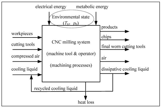
Figure 1.
The boundary of the assessment method.
2.2. Energy Analysis
Usually, the machining process of the CNC milling system can be broken up into seven stages according to the activities of the operator and the machine tool. The activities of the operator and the machine tool during the seven stages are shown in Table 1. Consequently, there are two kinds of energy consumption in the CNC milling system: energy consumption of the machine tool and energy consumption of the operator.

Table 1.
The activities during the seven stages.
2.2.1. Energy Consumption Modeling of the Machine Tool
According to the above-mentioned machining process stages, the energy consumption of the machine tool for machining a workpiece can be calculated as:
where EMT (J) is the energy consumption of the machine tool for machining a workpiece and EMT,i (J) is the energy consumption of the machine tool during stage i.
As for the machine tool, stage 5 (executing NC program activity) can be divided into two sub-stages: sub-stage 1 (air-cutting activity) and sub-stage 2 (material removal activity). So, the energy consumption of the machine tool during stage 5 can be expressed as:
where EMT,5−1 (J) is the energy consumption of the machine tool during sub-stage 1 (air-cutting activity) and EMT,5−2 (J) is the energy consumption of the machine tool during sub-stage 2 (material removal activity).
The energy consumption of the machine tool during each stage is a function of power and time. The power types of all machining process stages are divided as follows:
- (1)
- Standby power
Standby power is the basic power to keep the machine tool running where the main power is switched on; the electrical control systems and the numerical control system are running. Generally, the value of standby power is a constant, usually measured by experiment. The standby power can be measured as:
where Pstandby (W) is the machine tool electrical power consumption of standby activity, Pstandby,i (W) is the i-th measured value of the machine tool electrical power consumption of standby activity, and N is the number of the measured value.
- (2)
- Air-cutting power
Air-cutting power is the machine tool’s electrical power consumption of the air-cutting activity, in which the cutting tool moves with the tool path defined in the NC program without material removal. The air-cutting power, which consists of four parts: standby power, spindle rotation power, feed power, and cooling liquid supplying power, can be calculated by Equation (4) [].
where Pair-cutting (W) is the power consumption of the machine tool during sub-stage 1 (air-cutting activity), Pspindle (W) is the spindle rotation power, Pfeed (W) is the feed power, and Pcooling (W) is the cooling liquid supplying power treated as a constant value.
Pair-cutting = Pstandby + Pspindle + Pfeed + Pcooling
In addition, the spindle rotation power follows an approximately linear relationship with the rotational speed, which can be expressed as []:
where n (r/min) is the spindle rotational speed and k1 and b are the specific coefficients of the spindle motor.
Pspindle = k1n + b
Similarly, the feed power follows an approximately linear relationship with the feed rate, which is calculated as []:
where f (mm/min) is the feed rate and k2 and c are the specific coefficients of the feed motor. Based on Equations (4)–(6), the Pair-cutting can further be written as:
Pfeed = k2f + c
Pair-cutting = Pstandby + Pcooling + k1n + b + k2f + c
- (3)
- Material removal power
Material removal power is the machine tool’s electrical power consumption of the material removal activity where the cutting tool is in contact with the workpiece and the chips are produced. It can be expressed as []:
where Pmaterial removal (W) is the power consumption of the machine tool during sub-stage 2 (material removal activity), Pcutting (W) is the power consumption in the cutting tool tip when cutting the workpiece, MRR (mm3/s) is the material removal rate, k0 is the specific coefficient of the cutting force, ap (mm) is the cutting depth, and ae(mm) is the cutting width. Based on Equations (7)–(9), the Pmaterial removal can further be written as:
Pmaterial removal = Pair-cutting + Pcutting
Pcutting = k0MRR = k0 f ap ae/60
Pmaterial removal = Pstandby + Pcooling + k1n + b + k2f + c + k0MRR
In development, the EMT can be expressed as:
where ti (i = 1, 2, 3, 4, 6, 7) (s) is the duration of stage i, t5−1 (s) is the duration of sub-stage 1 (air-cutting activity), and t5−2 (s) is the duration of sub-stage 2 (material removal activity).
Moreover, according to the NC program, t5−1, t5−1, and t5 can be calculated as:
where Lair (mm) is the length of the cutting tool moving route during sub-stage 1 (air-cutting activity), Lcutting (mm) is the length of the cutting tool moving route during sub-stage 2 (material removal activity), and t5 (s) is the duration of stage 5.
It is worth noting that the energy consumption in the cutting tool tip used to remove material from the workpiece, “Ecutting [J]”, is defined as the effective energy output of the CNC milling system. It can be expressed as []:
In consequence, the traditional material removal energy efficiency of the machine tool can be calculated as []:
where ηe is the material removal energy efficiency of the machine tool.
2.2.2. Energy Consumption Modeling of the Operator
Similarly, the operations of the operator in the machining process can be broken up into seven activities. Each activity also generates massive energy consumption which has often been ignored in previous studies. The energy consumption of the operator is relevant to the activity intensity, the duration of each activity, and the features of the operator, such as height and body weight. As a matter of fact, different activities have different intensities that can be characterized by the average energy metabolic rate. On the other hand, the durations of the seven activities are diverse. Therefore, there are huge differences in the energy consumption of the operator during the seven stages. The descriptions and intensities of the seven activities are shown in Table 2.
Table 2.
Intensity of the seven activities of the operator.
The unit of the average energy metabolic rate is 1.0 kcal per minute per m2 body surface area. The body surface area is the function of the height and body weight of a human. For Chinese, it can be calculated as []:
where S (m2) is the body surface area of the operator, H (cm) is the height of the operator, and W (kg) is the body weight of the operator.
S = 0.006H + 0.0128W − 0.1529
According to the unit transformation between calories and joules, 1.0 kcal = 4184 J, the unit of activity intensity can be transformed as follows:
It is well known that 1 W = 1 J·s−1. So, Equation (16) can be transformed as follows:
where (W·m−2) is the power consumption of the operator per m2 body surface area.
According to the above-mentioned analysis, the operator energy consumption for machining a workpiece can be calculated as:
where EOP (J) is the energy consumption of the operator for machining a workpiece, EOP,i (J) is the operator energy consumption of activity i, and Pi (W) is the power consumption of the operator for activity i.
2.3. Exergy Analysis
Exergy is defined as the maximum obtainable work from a system, also called work potential. Unlike energy, which is conserved, exergy is not conserved, and it can be destructed in a system based on the second law of thermodynamics []. As no chemical reactions take place in the CNC milling process, the chemical exergy is not taken into account in this study. Additionally, under the environmental temperature, T0 (dead state), exergy transfer accompanying heat transfer in and out of the CNC milling system is zero. Therefore, the exergy balance equation of the CNC milling system can be expressed as:
where Exin (J) is the total exergy input to the CNC milling system; ExMT,in (J) and ExOP,in (J) represent the electrical exergy and mechanical exergy input, respectively; Exworkpiece,in (J), Exair,in (J), Extool,in (J), and Excooling,in (J) represent input exergies of the workpiece, compressed air, cutting tool, and cooling liquid, respectively; Exair,out (J), Extool,out (J), and Excooling,out (J) represent output exergies of the air, the worn cutting tool, and the cooling liquid, respectively; Exchip,out (J) is the exergy of chips; Exloss (J) is the total exergy loss of the CNC milling system; Exproduct,m (J) is the output mass exergy of the finished workpiece; and Exproduct,w (J) is the additional exergy of the finished workpiece, the value of which is equal to the electric energy consumption of the machine tool used to remove material from the workpiece, “Ecutting”.
The electrical energy consumed by the machine tool and the mechanical energy provided by the operator are “high-quality energy”, which means that they can be converted into useful work 100% [,]. So, the electrical exergy and mechanical exergy associated with the machine tool and the operator are expressed as:
What needs to be emphasized regarding the material flow in the machining process is that, although the material flow is consistent with the conservation of mass, the availability of the material is changed. For example, after the material removal process, the workpiece is changed into chips and a product. Compared to the workpiece, the availability of metal chips is reduced. But for the product, the required shape and high dimensional accuracy are obtained, which leads to the availability of the product being increased.
The above-mentioned exergy balance equation is complex because of numerous input and output factors. It can be simplified from the exergy loss perspective, which can be expressed as Equations (21) and (22):
where Exloss,energy (J), Exloss,chips (J), Exloss,air (J), Exloss,tool (J), and Exloss,cooling (J) represent the exergy loss of energy consumption, the exergy loss of chips, the exergy loss of compressed air, the exergy loss of cutting tool wear, and the exergy loss of cooling liquid dissipation, respectively.
The exergy loss of energy consumption means the total energy consumed by the machine tool and the operator except the actual energy computation used to remove the material. The exergy loss of chips is calculated by the exergy consumed in recycling chips to produce workpieces []. The exergy loss of compressed air means the exergy loss by pressure loss []. The exergy loss of cutting tool wear is the exergy apportionment of tool life []. The exergy loss of cooling liquid dissipation can be described as mass exergy transfer []. The specific calculation models for different kinds of exergy loss are presented in Table 3.
Table 3.
The calculation models for exergy loss.
In Equation (26), Ttool (min) is the cutting tool life, and it can be obtained using the following empirical formula []:
where Vc (m/min) is the cutting speed, fz (mm) is the feed per blade, ap (mm) is the cutting depth, and ae (mm) is the cutting width.
In order to describe the exergy efficiency of the CNC milling system, specific exergy loss (SEL) is put forward. SEL is defined as the ratio between the total exergy loss and the material removal volume []. Therefore, SEL is calculated as []:
where SEL (J/mm3) is the specific exergy loss of the CNC milling system and Vchips (mm3) is the volume of chips. SEL can be used to directly identify the exergy efficiency level of machine processing. The smaller the value of SEL, the more efficient it is, which also means a lower environmental burden.
3. Case Study
A three-axis machining center, some workpieces, and an operator form an actual CNC milling system were used to demonstrate the feasibility of the exergy loss assessment method. The case study consisted of two steps. First, a series of cutting experiments were carried out to match the coefficients of the power function, such as k0, k1, k2, b, and c. Second, a workpiece was machined to demonstrate the exergy loss assessment method.
3.1. Experimental Details
The case study was conducted on an XH714D three-axis machining center made by the Hanchuan CNC Machine Tool Co., Ltd., of China (Hanchuan, China). The power and energy consumption of the machine tool were measured by a Yokogawa WT1800 power analyzer. The power sensor was installed in the electric cabinet and it measured the main power input, as shown in Figure 2. The main parameters of the machine tool are listed in Table 4. The information about the operator is listed in Table 5.
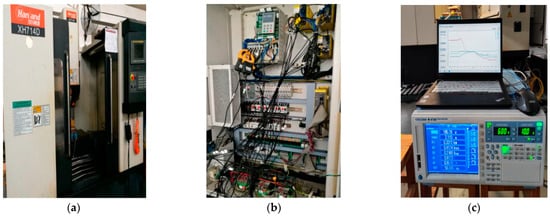
Figure 2.
XH714D experiment platform. (a) Machine tool. (b) Wiring diagram. (c) Data acquisition instrument.
Table 4.
The main parameters of the machine tool.
Table 5.
The information of the operator.
Furthermore, a workpiece with the dimensions 100 × 80 × 22 mm was used for face milling experiments. The material of the workpiece was medium-carbon steel (C45). The part drawings of the final product are shown in Figure 3.
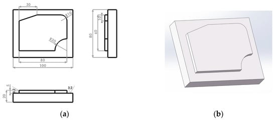
Figure 3.
Part diagrams of product. (a) Two-dimensional part diagram. (b) Three-dimensional part diagram.
According to the dimensions of the workpiece and the part drawings of the product, a face milling cutting tool and a shank cutting tool were used in the upper surface machining and the lug boss machining. The main parameters of the face milling cutting tool and the shank cutting tool are listed in Table 6. Moreover, the process card was made by the operator, as shown in Table 7. Based on the process card, the NC program was written by the operator.
Table 6.
The main parameters of the cutting tools.
Table 7.
Process card of the product.
In this case study, the temperature (T0) and pressure (P0) of the environment were 298.15 K and 0.1 MPa, respectively. The density, melting temperature, and energy consumption per unit of material smelting of chips were 7.85 g/cm3, 1808.15 K, and 9 MJ/kg, respectively. For compressed air, the flow rate, pressure, and molar gas constant (R) were 0.2 m3/min, 0.7 MPa, and 8.314 J/(mol·K), respectively. The specific exergy of the cutting tool was 401.5 MJ/kg, and there were two tool noses for one blade of the face milling cutting tool. The specific exergy of the cooling liquid was 42.287 MJ/kg, and the dissipation rate was 0.00368 g/s.
3.2. Results
- (1)
- The coefficients of the power model for the machine tool
Based on experimental testing and data collection, the standby power was 525 W on average and the cooling liquid supplying power was 40 W on average. Based on the fitting lines shown in Figure 4, the spindle rotation power is a function of spindle rotation speed. The fitting result is shown in Table 8.
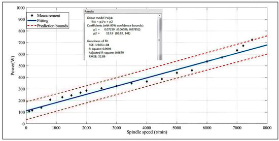
Figure 4.
The spindle rotation power function fitting.
Table 8.
Summary of power models.
As for the feed power, it was measured only along the X-axis. With the same situation (the same servo motor and mechanical transmission structure) as the X-axis, the feed power function of the Y-axis was considered the same as the X-axis. The feed power consumption of the Z-axis was ignored owing to low power consumption and low variability. The power consumption for the X-axis or Y-axis movements at defined feed rates is shown in Figure 5, and the fitting result is shown in Table 8.
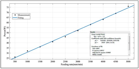
Figure 5.
The feed power function fitting.
The power consumption in the cutting tool tip, Pcutting (acquired by subtracting the air-cutting power from the material removal power), was measured by L9 orthogonal array tests with four factors and three levels, as shown in Table 9. The fitting result is shown in Table 8.
Table 9.
Test data and results of Pcutting and MRR.
- (2)
- Energy consumption analysis for machine tool and operator
Table 10 shows the durations and the energy consumption calculated by energy models for the machine tool and operator in seven machining stages. It can be seen that the energy consumption of the machine tool for machining the workpiece shown in Figure 3 is 758,211 J and the energy consumption of the operator is 169,750 J. The energy consumption of the operator is also enormous and should not be ignored. For the machine tool, the results show that most of the energy is consumed in sub-stage 2, sub-stage 1, and stage 3. The values are 324,830 J, 194,506 J, and 163,800 J, respectively. As for the operator, the results show that most of the energy is consumed in stage 3, stage 5, and stage 2. The values are 72,871 J, 52,585 J, and 17,289 J, respectively. The energy consumption in the cutting tool tip “Ecutting” is calculated as 139,626 J with Equation (13), and the traditional energy efficiency of machine tool “ηe” is calculated as 18.42% with Equation (14). This means that the XH714D three-axis machining center is energy-inefficient in machining the workpiece because abundant electrical energy is consumed in sub-stage 1 and stage 3.
Table 10.
Energy consumption details calculated by energy consumption models.
To demonstrate the accuracy of the above-mentioned energy models, the relative errors of calculated and measured values were selected, as shown in Figure 6. It can be seen that the total error between the calculated and measured value of energy consumption of the machine tool in this case study is 3.09%. The maximum error which appears in stage 3 is 4.82%. The main reason is that, in this paper, the machine tool is supposed to be in a standby state during stage 3. But, in fact, the machine tool has other activities resulting in extra energy consumption, such as spindle rotating, X-axis feeding, Y-axis feeding, Z-axis feeding, etc. The proposed energy consumption models of the machine tool provide an efficient calculation method with a high accuracy of 97%.
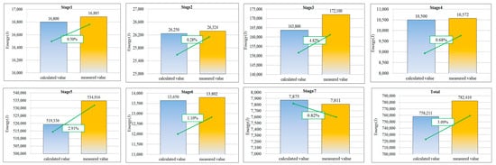
Figure 6.
The accuracy of the developed machine tool energy consumption models in all stages.
A deeper analysis of the proportions of energy consumption between the machine tool and operator during the seven stages was conducted. As shown in Figure 7, for stages 1, 2, and 6, the proportions of energy consumption for the operator are all 39.71%. The main reason for this is that during stages 1, 2, and 6, the machine tool is in the state of standby; at the same time, the activity intensities of the operator are equal. Meanwhile, for stages 3, 4, and 7, the proportions of energy consumption for the operator are 30.79%, 27.11%, and 27.88%, respectively. The proportion of energy consumption for the operator during stage 5 is relatively low (9.19%). This is because the activity of the machine tool is executing the NC program during stage 5 and the energy consumption is very significant (519,336 J). But the activity of the operator is only standing still. Consequently, the power consumption of the operator is relatively low (112.6 W) and the energy consumption is only 52,585 J. What needs to be pointed out is that the energy consumption of the operator accounts for 18.29% of the total energy consumption of the CNC milling system for machining the product. Obviously, the energy consumption of the operator should be taken into account if aiming for accurate and fine exergy loss assessment.
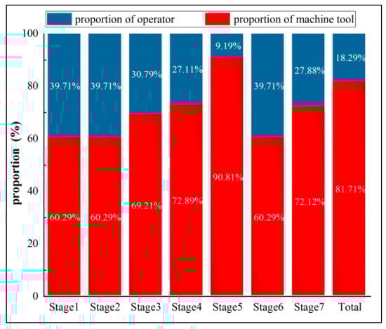
Figure 7.
Proportions of energy consumption for machine tool and operator.
- (3)
- Exergy loss analysis
Based on the experiments and calculations of exergy loss models, the values of all kinds of exergy loss are shown in Table 11. The exergy loss of energy consumption, chips, compressed air, cutting tool wear, and cooling liquid dissipation are 603,131 J, 2,031,404 J, 22,023 J, 301,868 J, and 2673 J, respectively. Furthermore, the specific exergy loss was calculated as 88.04 J/mm3 with Equation (29). This means that 88.04J energy is degenerated or destructed for unit material removal of the workpiece, which includes electrical energy consumption by the machine tool, the energy consumption by operators, and material flow consumption.
Table 11.
The values of the exergy loss and SEL.
The proportion distributions of exergy loss are shown in Figure 8. In this case, the proportions of exergy loss in five parts, in descending order, are such that the exergy loss of chips accounts for 67.02%, the exergy loss of energy consumption accounts for 19.90%, the exergy loss of cutting tool wear accounts for 9.96%, the exergy loss of cooling liquid dissipation accounts for 2.40%, and the exergy loss of compressed air accounts for 0.73%. Obviously, the top three are the exergy loss of chips, energy consumption, and the cutting tool wear.
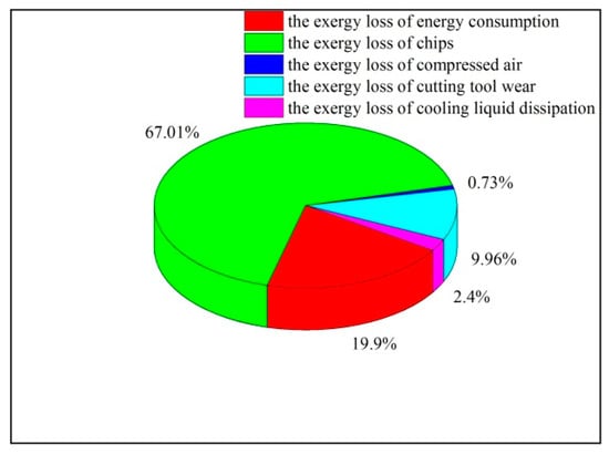
Figure 8.
Proportion distributions of the exergy loss.
4. Discussion
The energy consumption of the operator is 169,750 J during 922 s machining time in this case study, while the result is 36,739.2 J during 209.1 s machining time in the literature []. This means that the average power consumption of the operator is 184.1 W and 175.7 W in the machining system, respectively. It is significant to quantify the energy consumption of the operator with a modeling approach. In the literature [], the specific exergy consumption is calculated as 59.49 J/mm3 for an external cylindrical gear without considering the operator and the cooling liquid. The SEL model proposed in this study can provide a comprehensive assessment on the sustainability of different machining systems.
Meanwhile, some exergy-saving opportunities can be identified by exergy loss analysis. Generally, the higher the proportion of exergy loss, the greater exergy-saving potential. It can be found that a reduction in the generation of chips is the most effective way to improve the exergy efficiency because it dominates the total exergy loss. In order to reduce the exergy loss of chips, three suggestions have been proposed. Firstly, blanks or workpieces which have similar features in shape and size to the products are selected to reduce the amount of material removed during processing. Secondly, during the product design stage, lower-exergic-value materials replace higher-exergic-value materials to reduce the exergy loss of chips. Thirdly, additive manufacturing techniques are used whenever possible []. The exergy loss of energy consumption is the second largest. Obviously, exergy saving can also be realized by reducing energy consumption for machine tools and operators. At present, related scholars have done a lot of research on the energy consumption optimization for machine tools without considering the operator, which leads to non-optimal energy-saving strategies for machining systems []. The third largest exergy loss is the exergy loss of cutting tool wear. It is suggested that a reduction in the exergy loss of cutting tool wear can be achieved by using wear-resistant blades and choosing suitable cutting parameters to improve the life of the cutting tool. The exergy loss of cooling liquid dissipation and compressed air are both relatively low; therefore, they have the lowest exergy-saving potential.
5. Conclusions
In this paper, an exergy loss assessment method based on the second law of thermodynamics is proposed to investigate the sustainability of the CNC milling system, where the energy consumption of the operator, the energy consumption of the machine tool, and material flows are taken into consideration in one metric. The main contributions are as follows:
- The energy consumption of the operator is considered and modeled based on activity and activity intensity.
- Detailed power and energy consumption models of the machine are established from the perspective of machining stages division.
- The exergy-loss-based method considers both material and energy consumption in one metric in machining processes. Based on this, a novel exergy efficiency model (SEL) is established to investigate the comprehensive sustainability performance of the CNC milling system.
The case study shows that the method is an effective quantitative method to assess the sustainability of machining processes by exergy loss analysis. It has important significance for machining systems, for which exergy-saving opportunities can be identified. In future work, an effective measurement will be conducted to validate the accuracy of the energy consumption model of operators. Exergy efficiency improvement is another important issue. The optimization model of SEL will be thoroughly studied in the future.
Author Contributions
Conceptualization, Z.F. and H.Z.; methodology, Z.F.; validation, Y.Y., Y.G. and X.D.; investigation, W.L.; resources, H.Z.; writing—original draft preparation, Z.F.; writing—review and editing, H.Z.; supervision, H.Z. All authors have read and agreed to the published version of the manuscript.
Funding
This research was funded by the National Natural Science Foundation of China (grant number: 52375508) and the College Students’ Innovative Entrepreneurial Training Plan Program, China (grant number: S202310488141).
Acknowledgments
The authors acknowledge the support and inspiration of the Wuhan University of Science and Technology.
Conflicts of Interest
The authors declare no conflict of interest.
Nomenclature
| List of symbols | |||
| ap | The cutting depth (mm) | MRR | The material removal rate (mm3/s) |
| ae | The cutting width (mm) | n | The rotation speed of the spindle (r/min) |
| b | The coefficient of the spindle motor | nair | The amount of consumed compressed air (mol) |
| c | The coefficient of the feed motor | N | The number of measured values |
| echips | Energy consumption for per unit of material smelting of chips (MJ/kg) | Ntool | The number of tool noses for one blade |
| etool | The specific exergy of the cutting tool (MJ/kg) | P | The pressure of compressed air (MPa) |
| ecooling | The specific exergy of the cooling liquid (MJ/kg) | P0 | The pressure of the environment (MPa) |
| EMT | The machine tool energy consumption for machining a workpiece (J) | Pstandby | The machine tool electrical power consumption of standby activity (W) |
| EMT,i | The machine tool energy consumption of stage i (J) | Pstandby,i | The i-th measured value of the machine tool electrical power consumption of standby activity (W) |
| EMT,5-1 | The machine tool energy consumption of sub-stage 1 (J) | Pair-cutting | The power consumption of the machine tool during sub-stage1 (W) |
| EMT,5-2 | The machine tool energy consumption of sub-stage 2 (J) | Pmaterial removal | The power consumption of the machine tool during sub-stage 2 (W) |
| Ecutting | The energy consumption in the cutting tool tip used to remove material from the workpiece (J) | Pspindle | The spindle rotation power (W) |
| EOP | The operator energy consumption for machining a workpiece (J) | Pfeed | The feed power (W) |
| EOP, i | The operator energy consumption of activity i (J) | Pcooling | The cooling liquid supplying power (W) |
| Exloss, energy | The exergy loss of energy consumption (J) | Pcutting | The power consumption in the cutting tool tip when cutting the workpiece (W) |
| Exloss, chips | The exergy loss of chips (J) | rcooling | The dissipation rate of the cooling liquid (g/s) |
| Exloss, air | The exergy loss of compressed air (J) | R | The molar gas constant |
| Exloss, tool | The exergy loss of cutting tool wear (J) | S | The body surface area of the operator (m2) |
| Exloss, cooling | The exergy loss of cooling liquid dissipation (J) | SEL | The specific exergy loss (J/mm3) |
| f | The feed rate (mm/min) | ti | The duration of machining stage i (s) |
| fz | The feed per blade (mm) | t5−1 | The duration of sub-stage 1 (s) |
| H | The height of the operator (cm) | t5−2 | The duration of sub-stage 2 (s) |
| k0 | The specific coefficient of the cutting force | T0 | The temperature of the environment (K) |
| k1 | The coefficient of the spindle motor | Tchips | The melting temperature of chips (K) |
| k2 | The coefficient of the feed motor | Ttool | The life of the cutting tool (min) |
| Lair | The length of the cutting tool moving route during sub-stage1 (mm) | Vc | The cutting speed (m/min) |
| Lcutting | The length of the cutting tool moving route during sub-stage2 (mm) | Vchips | The volume of chips (mm3) |
| mchips | The weight of the chips (kg) | W | The body weight of the operator (kg) |
| mtool | One blade weight (kg) | z | The number of teeth |
| mcooling | The weight of the dissipated cooling liquid | ηe | The traditional material removal energy efficiency of the machine tool |
References
- Pang, Z.Q.; Liu, M. Research on the Current States and Measures of the Investment in the Equipment Manufacturing Industry in Gansu Province. J. Lanzhou Commer. Coll. 2008, 24, 72–79. (In Chinese) [Google Scholar]
- Cai, W.; Liu, F.; Zhou, X.N.; Xie, J. Fine energy consumption allowance of workpieces in the mechanical manufacturing industry. Energy 2016, 114, 623–633. [Google Scholar] [CrossRef]
- Dahmus, J.; Gutowski, T. An Environmental Analysis of Machining. In Proceedings of the ASME 2004 International Mechanical Engineering Congress and Exposition, Anaheim, CA, USA, 13–19 November 2004; pp. 643–652. [Google Scholar]
- Liu, S.; Liu, F.; Hu, S.; Yin, Z. Energy survey of machine tools: Separating power information of the main transmission system during machining process. J. Adv. Mech. Des. Syst. Manuf. 2012, 6, 445–455. [Google Scholar] [CrossRef][Green Version]
- Jia, S.; Yuan, Q.; Cai, W.; Li, M.; Li, Z. Energy modeling method of machine-operator system for sustainable machining. Energy Convers. Manag. 2018, 172, 265–276. [Google Scholar] [CrossRef]
- Wu, D.L.; Zhou, Y.F. Preliminary study on classification method of physical labor intensity in machinery manufacturing enterprises. Jidian Anquan 2005, 11, 7–13. (In Chinese) [Google Scholar]
- Ainsworth, B.E.; Haskell, W.L.; Herrmann, S.D.; Meckes, N.; Bassett, D.R., Jr.; Tudor-Locke, C.; Greer, J.L.; Vezina, J.; Whitt-Glover, M.C.; Leon, A.S. 2011 Compendium of Physical Activities: A second update of codes and MET values. Med. Sci. Sports Exerc. 2011, 43, 1575–1581. [Google Scholar] [CrossRef] [PubMed]
- Zhang, X.; Yu, T.; Dai, Y.; Qu, S.; Zhao, J. Energy consumption considering tool wear and optimization of cutting parameters in micro milling process. Int. J. Mech. Sci. 2020, 178, 105628. [Google Scholar] [CrossRef]
- Han, F.; Li, L.; Cai, W.; Li, C.; Deng, X.; Sutherland, J.W. Parameters optimization considering the trade-off between cutting power and MRR based on Linear Decreasing Particle Swarm Algorithm in milling. J. Clean. Prod. 2020, 262, 121338. [Google Scholar] [CrossRef]
- Gutowski, T.; Dahmus, J.; Thiriez, A. Electrical energy requirements for manufacturing processes. In Proceedings of the 13th CIRP International Conference on Life Cycle Engineering, Leuven, Belgium, 31 May–2 June 2006; pp. 623–628. [Google Scholar]
- Mori, M.; Fujishima, M.; Inamasu, Y.; Oda, Y. A study on energy efficiency improvement for machine tools. CIRP Ann. Manuf. Technol. 2011, 60, 145–148. [Google Scholar] [CrossRef]
- Li, L.; Yan, J.; Xing, Z. Energy requirements evaluation of milling machines based on thermal equilibrium and empirical modelling. J. Clean. Prod. 2013, 52, 113–121. [Google Scholar] [CrossRef]
- Zhang, Y.; Xu, H.; Huang, J.; Xiao, Y. Low-Carbon and Low-Energy-Consumption Gear Processing Route Optimization Based on Gray Wolf Algorithm. Processes 2022, 10, 2585. [Google Scholar] [CrossRef]
- Xiao, Y.; Liu, X.; Wang, R.; Zhang, H.; Li, J.; Zhou, J. Optimum Design of Square Blank Dimension with Low Energy Consumption and Low Cost for Milling Based on Business Compass Concept. Processes 2022, 10, 1514. [Google Scholar] [CrossRef]
- Lv, J.; Tang, R.; Jia, S. Therblig-based energy supply modeling of computer numerical control machine tools. J. Clean. Prod. 2014, 65, 168–177. [Google Scholar] [CrossRef]
- Jia, S.; Yuan, Q.; Lv, J.; Liu, Y.; Ren, D.; Zhang, Z. Therblig-embedded value stream mapping method for lean energy machining. Energy 2017, 138, 1081–1098. [Google Scholar] [CrossRef]
- Kara, S.; Li, W. Unit process energy consumption models for material removal processes. CIRP Ann. Manuf. Technol. 2011, 60, 37–40. [Google Scholar] [CrossRef]
- Balogun, V.A.; Edem, I.F.; Adekunle, A.A.; Mativenga, P.T. Specific energy based evaluation of machining efficiency. J. Clean. Prod. 2016, 116, 187–197. [Google Scholar] [CrossRef]
- Cai, W.; Liu, F.; Hu, S. An analytical investigation on energy efficiency of high-speed dry-cutting CNC hobbing machines. Int. J. Sustain. Eng. 2018, 11, 412–419. [Google Scholar] [CrossRef]
- Liu, Z.; Guo, Y. A hybrid approach to integrate machine learning and process mechanics for the prediction of specific cutting energy. CIRP Ann. Manuf. Technol. 2018, 67, 57–60. [Google Scholar] [CrossRef]
- Ghosh, S.; Chattopadhyay, A.B.; Paul, S. Modelling of specific energy requirement during high-efficiency deep grinding. Int. J. Mach. Tools Manuf. 2008, 48, 1242–1253. [Google Scholar] [CrossRef]
- Heinzel, C.; Kolkwitz, B. The impact of fluid supply on energy efficiency and process performance in grinding. CIRP Ann. Manuf. Technol. 2019, 68, 337–340. [Google Scholar] [CrossRef]
- Ma, F.; Zhang, H.; Gong, Q.; Hon, K.K.B. A novel energy efficiency grade evaluation approach for machining systems based on inherent energy efficiency. Int. J. Prod. Res. 2021, 59, 6022–6033. [Google Scholar] [CrossRef]
- Liu, P.; Zhang, Z.; Wang, X.; Li, X.; Wang, X.V.; Tuo, J. A generalized method for the inherent energy performance modeling of machine tools. J. Manuf. Syst. 2021, 61, 406–422. [Google Scholar] [CrossRef]
- Tuo, J.; Liu, F.; Liu, P.; Zhang, H.; Cai, W. Energy efficiency evaluation for machining systems through virtual part. Energy 2018, 159, 172–183. [Google Scholar] [CrossRef]
- Tuo, J.; Liu, F.; Liu, P. Key performance indicators for assessing inherent energy performance of machine tools in industries. Int. J. Prod. Res. 2019, 57, 1811–1824. [Google Scholar] [CrossRef]
- Yu, Z.; Völgyi, E.; Wang, R.; Ember, A.; Wiklund, P.; Alén, M.; Tylavsky, F.A.; Cheng, S. Comparison of heart rate monitoring with indirect calorimetry for energy expenditure evaluation. J. Sport Health Sci. 2012, 1, 178–183. [Google Scholar] [CrossRef]
- Harrington, D.M.; Martin, C.K.; Ravussin, E.; Katzmarzyk, P.T. Activity related energy expenditure, appetite and energy intake: Potential implications for weight management. Appetite 2013, 67, 1–7. [Google Scholar] [CrossRef] [PubMed]
- Zhang, C.H.; Ding, W.G.; Ding, S.T.; Xue, Q. Energy Expenditure Modeling for Walking Soldier. Comput. Simul. 2005, 4, 241–243. (In Chinese) [Google Scholar]
- Choi, A.C.K.; Kaebernick, H.; Lai, W.H. Manufacturing processes modelling for environmental impact assessment. J. Mater. Process. Technol. 1997, 70, 231–238. [Google Scholar] [CrossRef]
- Shen, Z.; Zhao, X. Evaluation of Resource Utilization Efficiency in the Machining Process Based on the SBM-DEA Model with Non-Expected Output. Processes 2023, 11, 916. [Google Scholar] [CrossRef]
- Munoz, A.A.; Sheng, P. An analytical approach for determining the environmental impact of machining processes. J. Mater. Process. Technol. 1995, 53, 736–758. [Google Scholar] [CrossRef]
- Liu, F.; Zhang, H.; Wu, P.; Cao, H.J. A model for analyzing the consumption situation of product material resources in manufacturing systems. J. Mater. Process. Technol. 2002, 122, 201–207. [Google Scholar] [CrossRef]
- Jiang, Z.; Zhou, F.; Zhang, H.; Wang, Y.; Sutherland, J.W. Optimization of machining parameters considering minimum cutting fluid consumption. J. Clean. Prod. 2015, 108, 183–191. [Google Scholar] [CrossRef]
- Gutowski, T.G.; Branham, M.S.; Dahmus, J.B.; Jones, A.J.; Thiriez, A.; Sekulic, D.P. Thermodynamic Analysis of Resources Used in Manufacturing Processes. Environ. Sci. Technol. 2009, 43, 1584–1590. [Google Scholar] [CrossRef]
- Renaldi; Kellens, K.; Dewulf, W.; Duflou, J.R. Exergy Efficiency Definitions for Manufacturing Processes. In Glocalized Solutions for Sustainability in Manufacturing, Proceedings of the 18th CIRP International Conference on Life Cycle Engineering, Braunschweig, Germany, 2–4 May 2011; Springer: Berlin/Heidelberg, Germany, 2011; pp. 329–334. [Google Scholar]
- Renaldi; Kellens, K.; Dewulf, W.; Duflou, J.R. On the Implementation of Exergy Efficiency Metrics in Discrete Manufacturing System: The Dissipative Nature of Production Processes. In Proceedings of the 19th CIRP International Conference on Life Cycle Engineering, Berkeley, CA, USA, 23–25 May 2012; pp. 545–550. [Google Scholar]
- Renaldi; Kellens, K.; Dewulf, W.; Duflou, J.R. Resource efficiency assessment of discrete manufacturing processes: Comparison between energy- and exergy-based metrics. In Proceedings of the EcoDesign 2011 International Symposium, Kyoto, Japan, 30 November–2 December 2011; pp. 645–650. [Google Scholar]
- Salman, P.; Mohamed, G. Exergy analysis of metal cutting processes. In Proceedings of the ASME 2016 International Mechanical Engineering Congress and Exposition, Phoenix, AZ, USA, 11–17 November 2016; IMECE2016-68035. pp. 1–8. [Google Scholar]
- Salman, P.; Mohamed, G. Exergy analysis of a machining operation using finite element (fe) assisted simulations. In Proceedings of the ASME 2018 International Mechanical Engineering Congress and Exposition, Pittsburgh, PA, USA, 9–15 November 2018; IMECE2018-88494. pp. 1–9. [Google Scholar]
- Ghandehariun, A.; Nazzal, Y.; Kishawy, H.A.; Al-Arifi, N.S.N. Investigation of sustainability in machining processes: Exergy analysis of turning operations. Int. J. Exergy 2015, 17, 1–15. [Google Scholar] [CrossRef]
- Ghandehariun, A.; Hosseini, A.; Deiab, I.; Hussein, H.M.A.; Kishawy, H.A. Sustainability investigation of drilling: Exergy analysis of conventional and peck drilling approaches. Int. J. Exergy 2016, 21, 369–382. [Google Scholar] [CrossRef]
- Li, B.; Cao, H.; Hon, B.; Liu, L.; Gao, X. Exergy-based Energy Efficiency Evaluation Model for Machine Tools Considering Thermal Stability. Int. J. Precis. Eng. Manuf.-Green Technol. 2021, 8, 423–434. [Google Scholar] [CrossRef]
- Kasabova, B.E.; Holliday, T.W. New model for estimating the relationship between surface area and volume in the human body using skeletal remains. Am. J. Phys. Anthropol. 2015, 156, 614–624. [Google Scholar] [CrossRef] [PubMed]
- Li, L.; Guo, C.; Yan, J.; Zhao, F.; Sutherland, J.W. Exergy-based tool path evaluation method of material and energy flows to support the sustainable-oriented intelligent manufacturing. Proc. Inst. Mech. Eng. Part C J. Mech. Eng. Sci. 2022, 136, 1960–1972. [Google Scholar] [CrossRef]
- Hu, Q.B. Study on Energy Efficiency Optimization and Estimation of Carbon Emissions for NC Milling Based on the Exergy Analysis. Ph.D. Thesis, Harbin Institute of Technology, Harbin, China, 2017. (In Chinese). [Google Scholar]
- Li, L. Energy Consumption Optimization and Exergy Loss Assessment Method For CNC Machining Process. Ph.D. Thesis, Harbin Institute of Technology, Harbin, China, 2016. (In Chinese). [Google Scholar]
- Wang, C.F. Modeling and Experimental Study on Tool Wear Life in High-speed Milling. Manuf. Technol. Mach. Tool 2008, 11, 84–87. (In Chinese) [Google Scholar]
Disclaimer/Publisher’s Note: The statements, opinions and data contained in all publications are solely those of the individual author(s) and contributor(s) and not of MDPI and/or the editor(s). MDPI and/or the editor(s) disclaim responsibility for any injury to people or property resulting from any ideas, methods, instructions or products referred to in the content. |
© 2023 by the authors. Licensee MDPI, Basel, Switzerland. This article is an open access article distributed under the terms and conditions of the Creative Commons Attribution (CC BY) license (https://creativecommons.org/licenses/by/4.0/).