Article

Research on the Positioning Accuracy of the Cutting Head of a Tunneling Machine Based on Ultra-Wideband Positioning Technology

School of Energy and Mining Engineering, China University of Mining and Technology (Beijing), Beijing 100083, China
*
Author to whom correspondence should be addressed.
Processes 2023, 11(9), 2534; https://doi.org/10.3390/pr11092534
Submission received: 25 July 2023 / Revised: 14 August 2023 / Accepted: 16 August 2023 / Published: 24 August 2023
(This article belongs to the Special Issue Intelligent Safety Monitoring and Prevention Process in Coal Mines)

Abstract

:
Directed at the problems of low positioning accuracy and irregular section forming of cutting heads of road header in coal mine production sites, a new cutting head positioning system based on ultra-wideband positioning technology is proposed based on the cutting head motion model and the working principle of ultra-wideband positioning technology, which verifies the anti-interference and the accuracy of its positioning. Combined with the simulation experiment under on-site working conditions, the influence degree of three typical influencing factors on positioning accuracy was obtained, and the accuracy optimization of the ultra-wideband positioning system was guided. Through the dynamic solution experiment, the positioning accuracy of the system is measured, and the results are verified based on the positioning system solution accuracy evaluation standard.

1. Introduction

The unmanned and intelligent coal production site is the main trend of the development of the current coal industry. In order to meet the needs of safe and efficient production on the coal mine site and improve the efficiency of mining replacement, the tunneling equipment is gradually transitioning to intelligence and automation [1,2,3,4]. At present, the cantilever roadheader has become the most widely used tunneling equipment in coal mines because of its strong universality, high tunneling efficiency, and advanced section control precision. Limited by the special working conditions of the coal mine site, the mining cantilever roadheader will be affected by factors such as occlusion, dust concentration, ranging spatial position, and so on when carrying out the cutting operation. Even most of the tunneling face needs manual observation and operation to complete the tunneling process, resulting in the decrease in the positioning accuracy of the cutting head, which directly affects the tunneling efficiency of the roadheader, and causes a series of problems, such as irregular formation of local roadway section [5,6,7,8,9].
With the actual production needs, domestic and foreign experts and scholars have conducted extensive research on the application of positioning technology of mining cantilever roadheader and adopted a variety of technical routes to achieve accurate positioning of the cutting head. Zhang M et al. [10] designed a positioning decision program by using a fuzzy decision controller, fuzzy logic controller, and dynamic error elimination controller. The mathematical model was established by the functional relationship between the pitch angle and the hydraulic cylinder. The experimental test of the decision program effectively improved the positioning accuracy. Cheluszka P et al. [11] used visual ranging technology to realize the positioning of the cutting head, analyzed the positional relationship between the roadheader base and the cutting head, established the measurement model, and calculated the positional relationship between the base datum and the cutting head. Du et al. [12] comprehensively analyzed various positioning methods and believed that machine vision technology is most suitable for the positioning of mine cantilever roadheader and designed a set of real-time monitoring system for the position and posture of the fuselage and the spatial position of the cutting head. Wu Miao et al. [13] proposed a walking trajectory and deviation perception method of cantilever roadheader based on a strapdown inertial navigation system, which can determine the azimuth deviation of roadheader fuselage in real-time and provide correction reference parameters for directional tunneling.
Many experts and scholars have carried out a lot of analysis and research from different angles on automation and intelligent research on the precise positioning of the cutting head of the mining cantilever roadheader, which provides a solid theoretical basis for the precise operation of the roadway excavation automation. However, the current mainstream roadheader positioning technology mainly obtains the pose information of the roadheader fuselage, and then indirectly determines the spatial coordinates of the cutting head through calculation. The indirect positioning method is affected by the roadheader fuselage’s vibration and the moving joints’ influence, and there is a certain accuracy error. On the other hand, the current cutting head positioning technology is numerous, but the applicability is limited, the underground working environment is relatively poor, and the positioning accuracy of many advanced electronic components on the ground is ideal, but the positioning accuracy in the underground is greatly reduced [14,15,16,17]. Through the multi-dimensional comparative analysis of wireless positioning technology, it is found that ultra-wideband positioning technology has outstanding advantages in positioning accuracy, positioning range and anti-interference ability. Based on the motion model of cutting head and the working principle of ultra-wideband positioning technology, this paper proposes a new cutting head positioning system based on ultra-wideband positioning technology, which can realize the direct positioning of cutting head and ensure good positioning accuracy.

2. Ultra-WideBand (UWB) Positioning Technology and Simplified Cutting Head Motion Model

2.1. Ultra-WideBand (UWB) Positioning Technology

Ultra-wideband positioning technology is a new positioning method, which in its early stage, was only used in the military field. Since the end of the last century, with the progressive maturity of its supporting equipment and cost reduction, it has gradually moved to the civilian field, and under the vision of intelligent coal mines, it has been recognized as the priority development and application direction of wireless positioning. Compared with many traditional narrowband communication technologies, UWB technology has many technical advantages, such as high positioning accuracy, strong penetration ability, simple structure, low power consumption, strong anti-interference ability, and low radiation. The characteristics of UWB technology make it suitable for high-resolution wireless positioning.
In this study, the ultra-wideband positioning base station, positioning tag, and its supporting debugging and monitoring software for coal mines provided by ANTEXIN (Beijing) Company were used to carry out related experiments. The integrated ultra-wideband ranging module of the internal circuit board of the equipment was built based on the DW1000 chip. The equipment has IIC intrinsically safe explosion-proof certification after packaging, which is specially designed and applied to coal mines, and is fully applicable to the environment of tunneling working face. The internal circuit board of the equipment integrates DW1000 ultra-wideband positioning chip, which can greatly reduce the application difficulty and cost. Accurate ranging is performed by signal time-of-flight ranging. The indoor positioning accuracy is high, and the dynamic tracking ability of positioning is strong. Strong anti-interference ability.

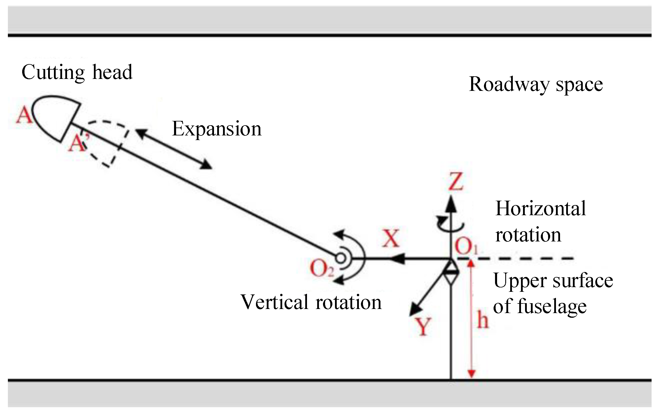
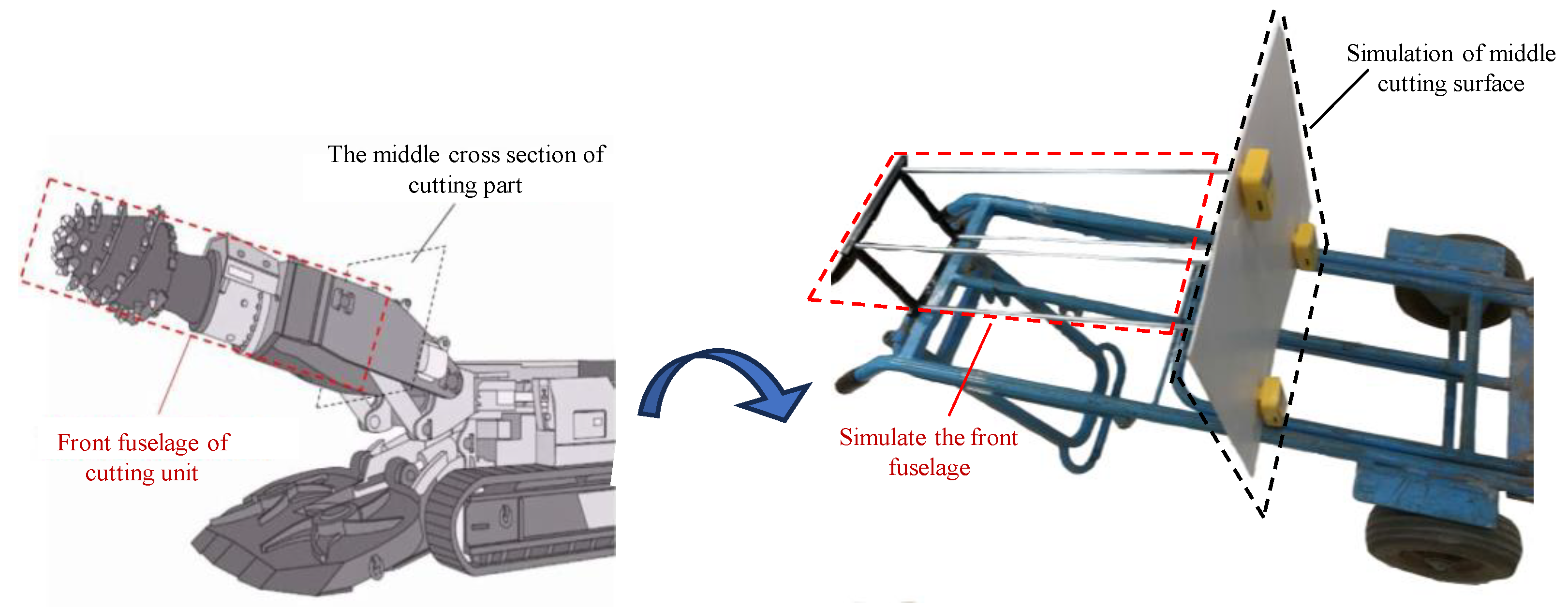
2.2. Simplified Cutting Head of Roadheader Motion Model

The cutting part of the boom-type roadheader is composed of a cutting head, a cutting arm, multiple sets of hydraulic cylinders, and a cutting motor. In the cutting operation of the cutting part, the cutting part is the main working actuator, which is driven to rotation by the cutting motor, and the coal rock crushing is completed by the cutting collision of the pick and the coal rock wall. During the excavation and cutting operation, if the structure of the roadheader fuselage is fixed, the cutting head can only cut the coal and rock mass with a fixed small section area. To complete the cutting operation of the whole working face, it is necessary to move the relevant motion mechanism, so that the spatial position of the cutting head changes with the demand, so as to cut the coal and rock mass with a large section area and meet the section size requirements [18,19,20].
The position of the cutting head during the cutting operation of the cantilever roadheader in the roadway space is analyzed. Based on the reference coordinate system of the roadway, the motion model of the cutting part is established according to the working principle of the horizontal and vertical rotation mechanism of the cutting part, as shown in Figure 1. The cutting section has two rotation centers: O1 for horizontal rotation, located at the front center of the main body, and O2 for vertical rotation, located in the X-axis direction. The cutting arm rotates around O1 to complete the horizontal rotation and around O2 to complete the vertical rotation. A and A′ are the top positions of the cutting head when the cutting arm expansion cylinder is at maximum and minimum stroke, respectively. Through the rotation state of the cutting part in the vertical and horizontal directions, the pose of the cutting arm can be comprehensively determined. Combined with the length of the cutting arm, the position of the cutting head can be determined, and the positioning of the cutting head in the roadway coordinate system can be completed.

3. Cutting Head Ultra-Wideband Positioning System Simulation Experiment

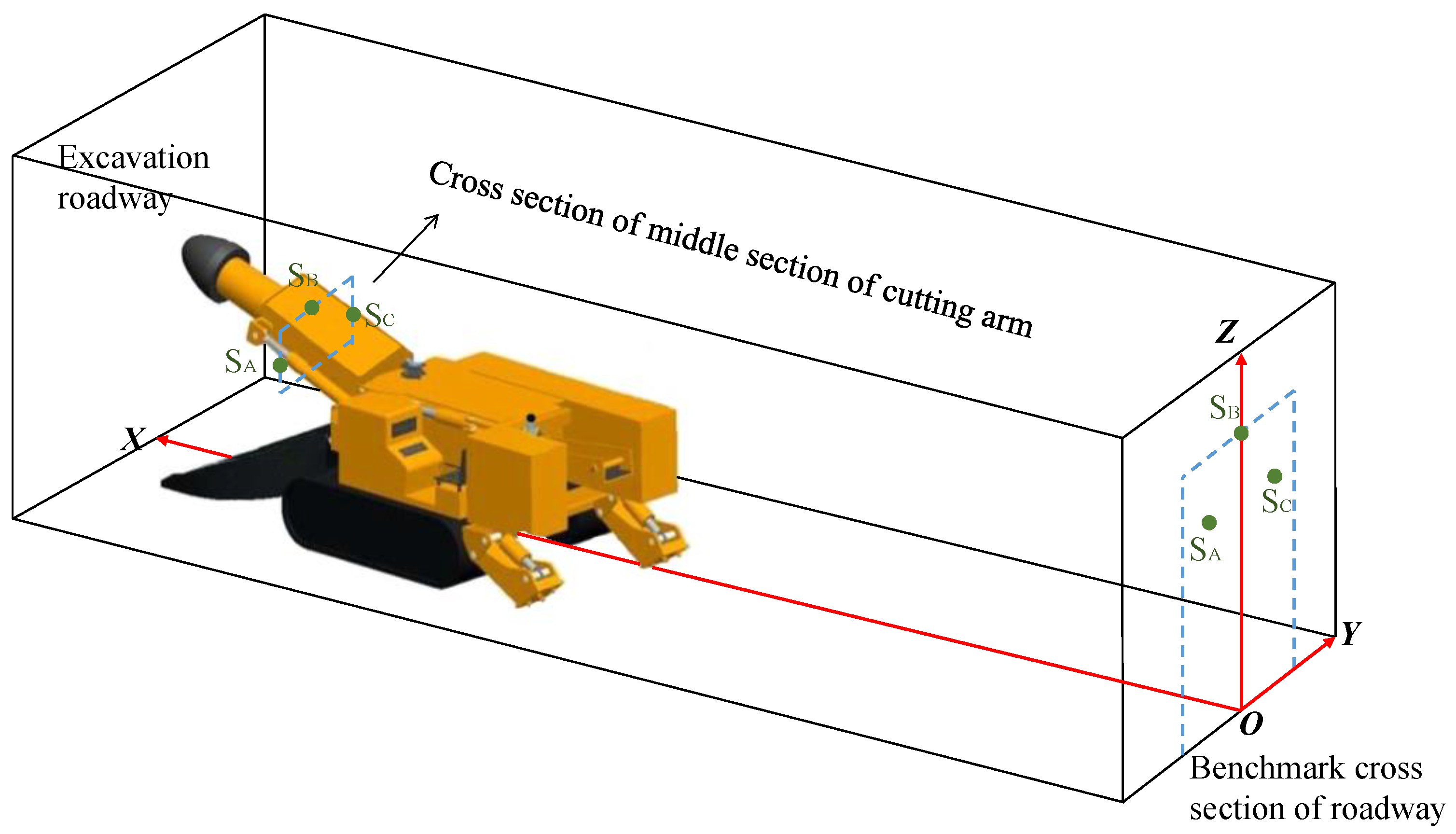
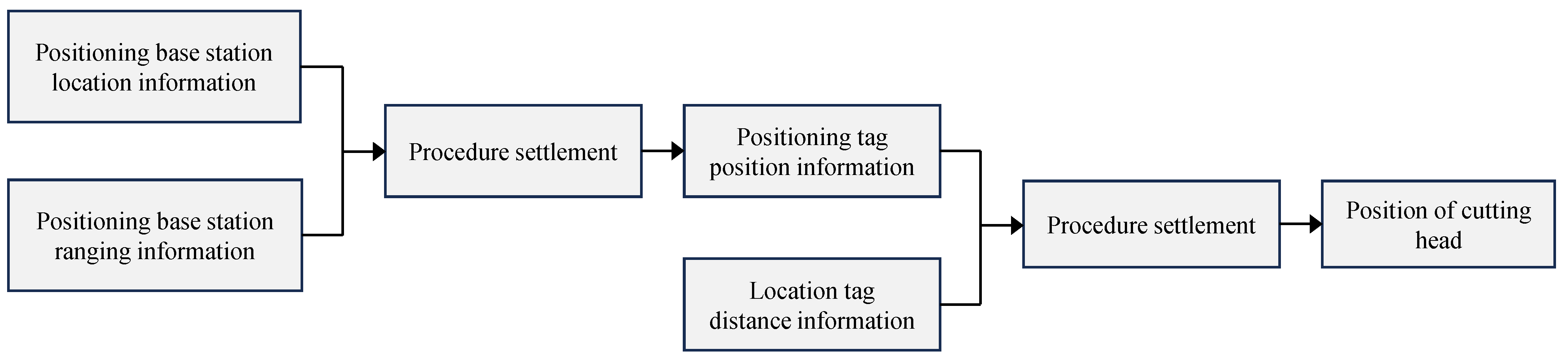
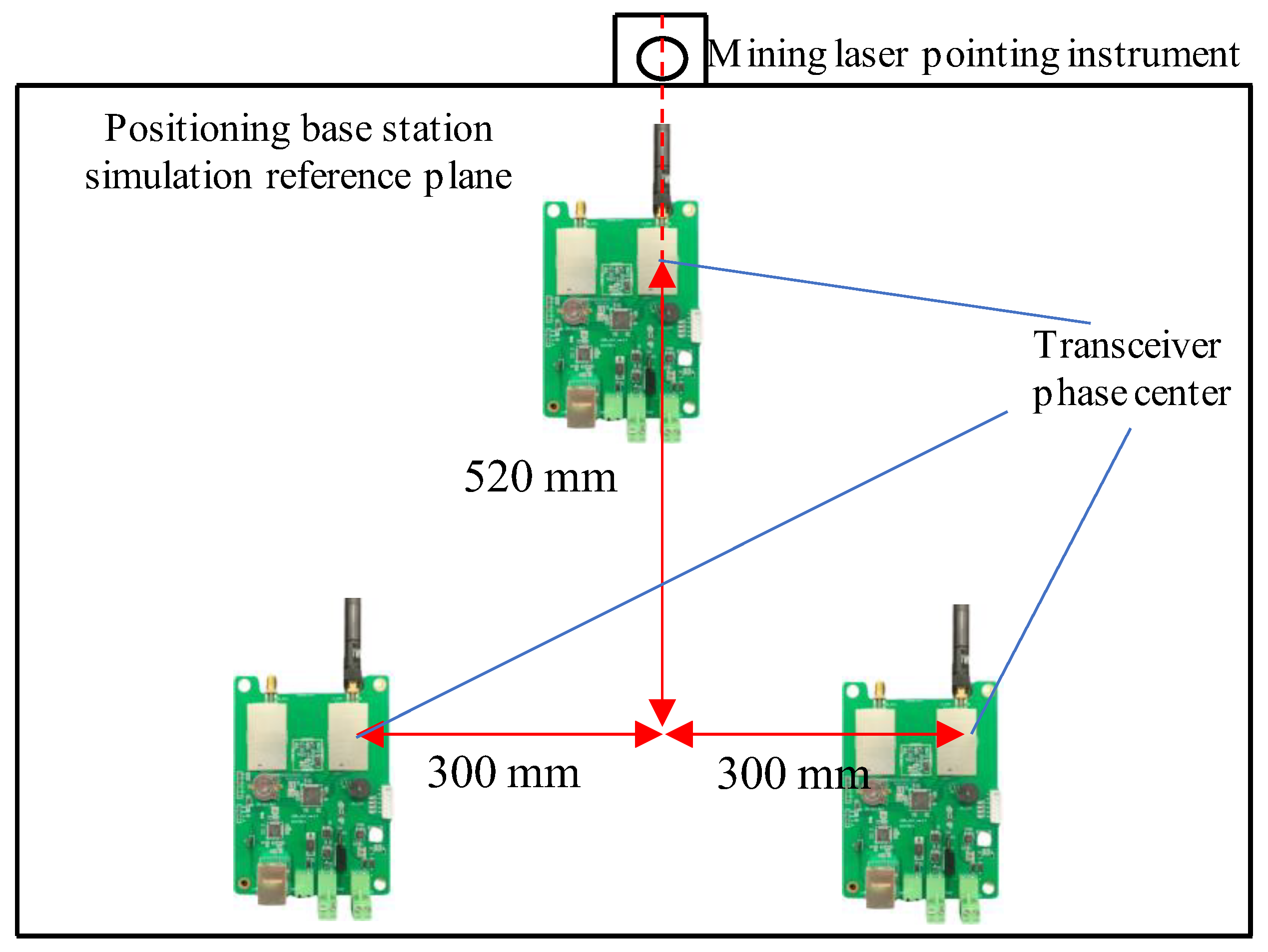
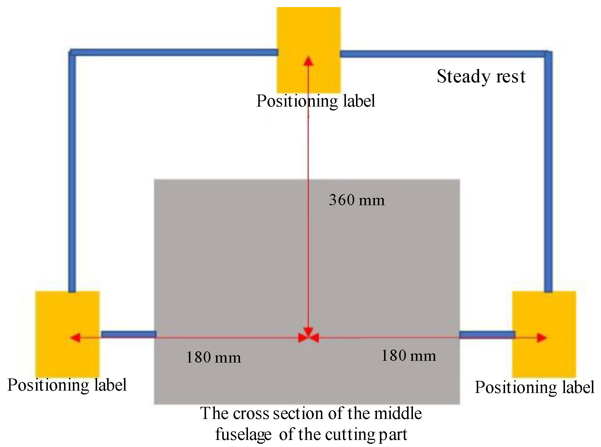
3.1. Experimental Principles

In order to test the accuracy, precision and anti-interference of the roadheader cutting head positioning system based on ultra-wideband positioning technology, based on the cutting head motion model and the working principle of ultra-wideband positioning technology, a simulation experiment was designed around the actual working environment of the underground tunneling face.
① Simulated positioning base station reference plane
On the cross-section of the roadway where the laser pointer is installed behind the tunneling face, a reference plane of the positioning base station is set up. Three ultra-wideband positioning base stations are arranged on this plane, and the instrument is fixed by the fixed support.
② Simulate the cross-section of the middle section of the cutting part
On the shell of the middle section of the cutting part of the roadheader, the cross-section of the middle section of the cutting part is set up on the premise of not affecting the normal operation of the equipment. Three ultra-wideband positioning tags are arranged in this plane, and the positioning tags are fixed by the fixed bracket.
The comprehensive arrangement of the simulation experiment is shown in Figure 2.
The ultra-wideband positioning system of the cutting head is based on sensor wireless ranging technology. By arranging the position-calibrated sensors SA, SB, and SC on the cross-section of the appropriate position in the middle and rear section of the cutting arm and arranging the position-calibrated sensors S1, S2, and S3 on the cross-section of the roadway reference coordinate system behind the cantilever roadheader, the ranging parameters are obtained. Relying on the system logic solution, according to the distance measurement values of each sensor and sensors S1, S2, and S3 on the middle section of the cutting arm and the spatial coordinates of sensors S1, S2, and S3 in the roadway reference coordinate system, the spatial coordinates of sensors SA, SB, and SC are obtained, so as to determine the real-time pose of the cutting arm. According to the installation and calibration dimensions of SA, SB, and SC, the position of the cutting head in the standard coordinate system of the roadway can be solved. The operation process of the positioning system is shown in Figure 3.

3.2. Components of Positioning System

The simulation experiment platform of the ultra-wideband positioning system of the cutting head is composed of two parts: hardware and software. The hardware part of the platform includes an ultra-wideband positioning base station circuit board and supporting transceiver antenna 3 sets; antenna 3 sets; three ultra-wideband positioning tags; one gigabit five-port switch, one mine laser pointer, and one portable server; several groups of simulated brackets and fixed plates; several bundles of wire used to connect the equipment; several sets of power supply and power lines for equipment power supply. The software part mainly includes wireless positioning base station configuration tool software, debugging tool software, and MATLAB cutting head 3D coordinate calculation program, which work together to achieve the data and experimental objectives required for the simulation experimental platform. The hardware components of the platform can meet the various needs of the simulation experiment and comply with the technical requirements and safety standards of the simulation experiment. The related experimental device is shown in Figure 4.
The ultra-wideband positioning base station is installed on the reference cross-section of the roadway behind the underground heading face, and the calibration laser pointer is also installed at this position. The base station is arranged in a triangular array, and the position and orientation of the phase center of the three transceivers are consistent and in the same plane. In the simulation experiment, the installation layout and size of the ultra-wideband positioning base station in the actual working condition are simulated on the reference plane of the simulated positioning base station, and the installation layout size is consistent with the actual situation. The layout size is shown in Figure 5.
The positioning label completes the position calibration through the fixed bracket according to the size of the cutting part in the actual working condition. In the simulation experiment, the fixed plate is used to complete the position calibration on the cross-section of the middle section of the simulated cutting part. The accuracy of the positioning solution that needs to be analyzed in the follow-up simulation experiment, so in addition to the positioning base station, the layout and assembly size of each simulated structural component should be consistent with the actual working condition size, and the ratio of the simulated experimental layout size to the actual working condition layout size is set to 1:5. The layout size of the positioning label is shown in Figure 6.

4. Analysis of Interference Factors of System Positioning Accuracy

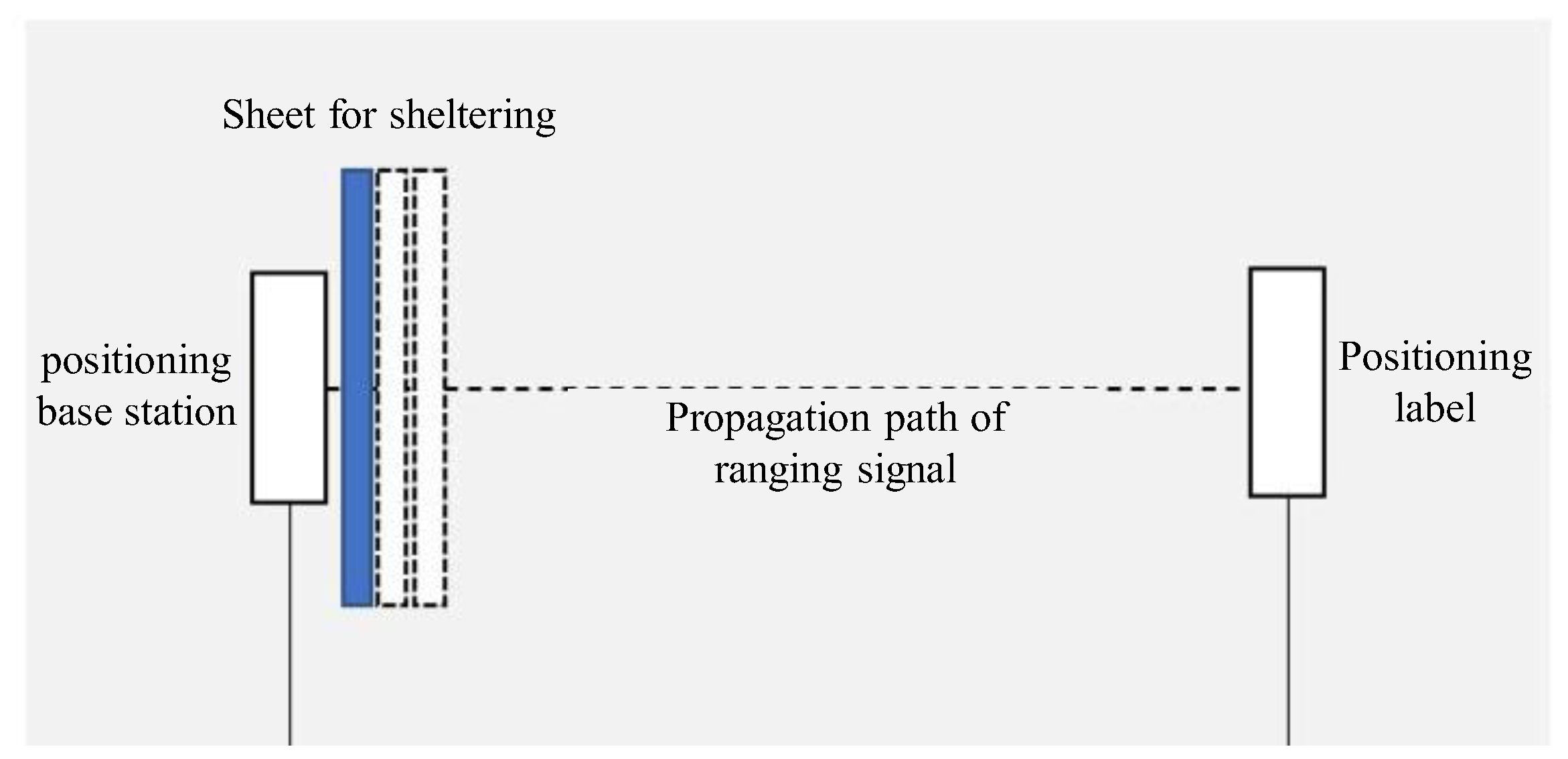
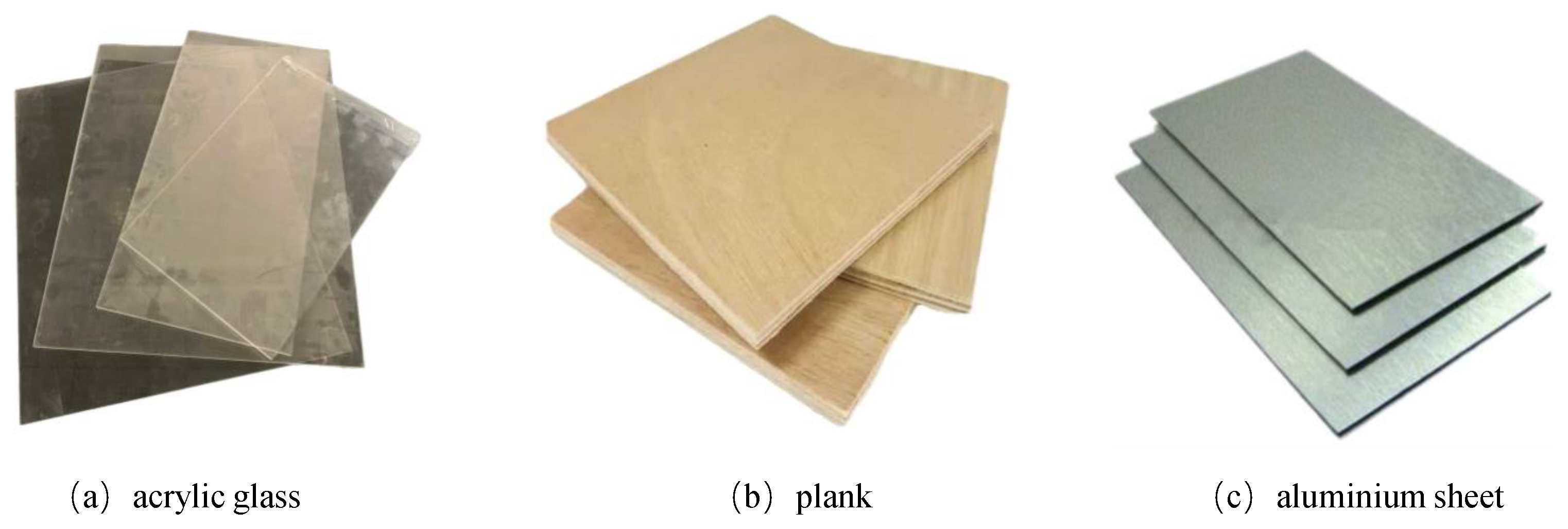
4.1. Direct Occlusion Effects

The working environment of the heading face is relatively harsh. When the positioning system is put into field application, each precision component needs to be equipped with an explosion-proof and dust-proof shell, and at least two layers of material will be blocked on the linear propagation path of the ranging module signal. Therefore, based on the simulation experiment platform of the ultra-wideband positioning system of the cutting head, the direct occlusion effect experiment is carried out to analyze the interference of different material shells on the accuracy, and to determine the influence of physical properties such as material type, thickness, and wave transmission on the accuracy. Therefore, it is convenient to select materials with less precision interference to make the shell of the ultra-wideband positioning system equipment, so as to reduce the degree of positioning accuracy interference and ensure the accuracy of the positioning system.
In order to explore the influence of different material shells on the ranging accuracy of the ultra-wideband positioning system, the control variable comparison method was used for experiments. The experimental process is shown in Figure 7.
A set of experimental positioning base stations and tags are selected as the experimental subjects. The fixed bracket is used to calibrate the attitude and relative position of the positioning base station and the positioning tag. Three acrylic plates, wood plates, and aluminum plates of similar thickness are prepared to ensure that their area can block the signal propagation path of the ranging module. The experimental plate is shown in Figure 8.
The positioning base station and positioning tag are placed and fixed in the experimental space, and the posture and relative position of the equipment are calibrated to make the positioning base station and the positioning tag face-to-face. The ranging data are recorded, and the data are read within 30 s. The average value is taken as the ranging reference value, and the spatial position of the positioning base station and the positioning tag is kept unchanged. One to three layers of the same material plates are placed on the signal transmission path between the ranging base station and the ranging tag, and the three columns of ranging values are recorded by reading the reference value. By changing a material plate for three readings of the next set of experiments, a total of three sets of nine-column ranging values are obtained. Comparing the ranging value of each group with the ranging reference value, the trend of error value is shown in Figure 9.
From the above experimental results, it can be seen that the error value of the three experiments of the acrylic plate group is very small, the error fluctuation level is very low, and the ranging error is within 20 mm. The three experimental error values of the board group are also small, the error fluctuation level is low, and the ranging error is always within 50 mm.
The dynamic reading of the aluminum plate experimental group is shown in Figure 10. It can be seen from the figure that when the aluminum plate is blocked in the ranging signal path, the module reading fluctuates dramatically. The ranging value of the aluminum plate group experiment is seriously distorted, and the error is extremely large, up to more than 1000 mm. We have been unable to analyze the error level, and the degree of interference is severe, which seriously affects the normal operation of the ranging module.
According to the analysis, the acrylic plate has little effect on the ultra-wideband signal propagation, the wood plate has little effect on the ultra-wideband signal propagation, and the aluminum plate has a serious effect on the ultra-wideband signal propagation. As a narrow pulse signal, the ultra-wideband itself has a strong ability to penetrate the medium. Both the acrylic plate and the wood plate have good wave permeability, and within the conventional thickness, they will not affect the accuracy level required by the system. The poor wave permeability of metal plates, such as aluminum plates, will seriously interfere with the ranging accuracy regardless of the thickness, thus affecting the positioning accuracy of the system. Therefore, plastic materials, such as acrylic, should be preferred for the packaging shell of the positioning system.

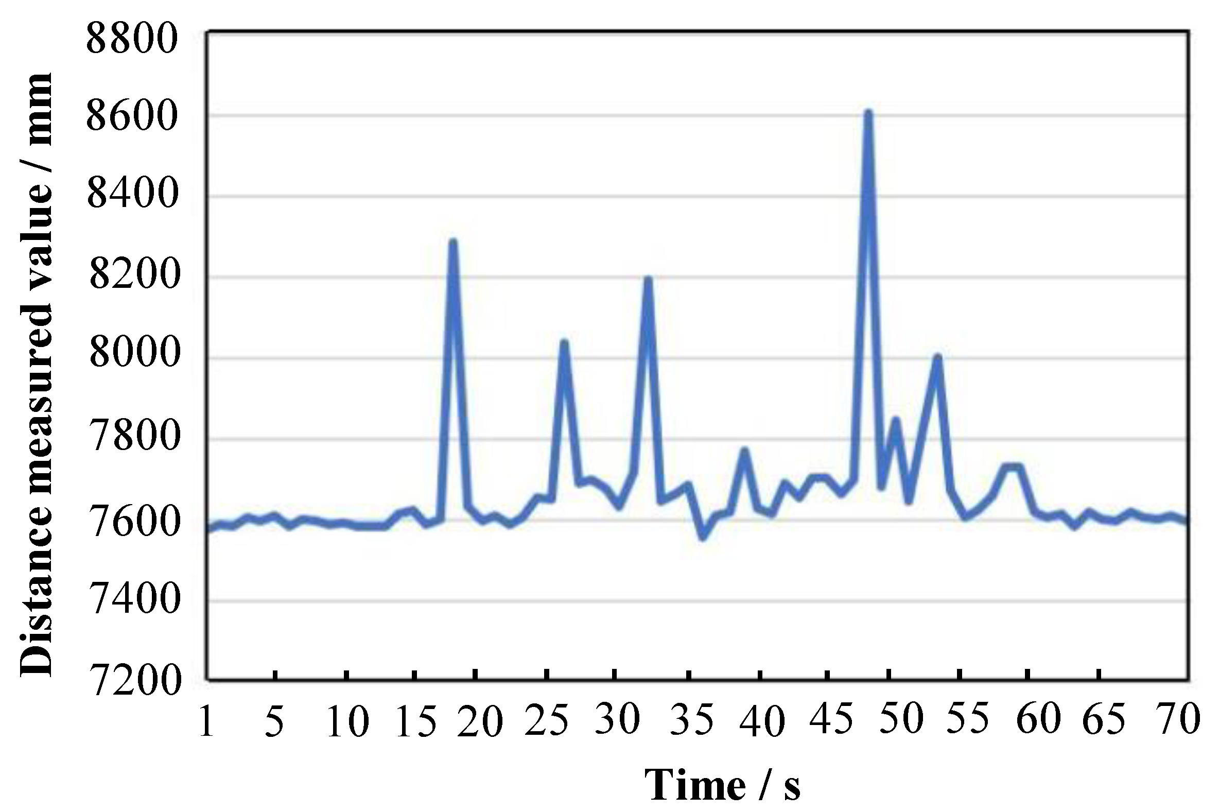
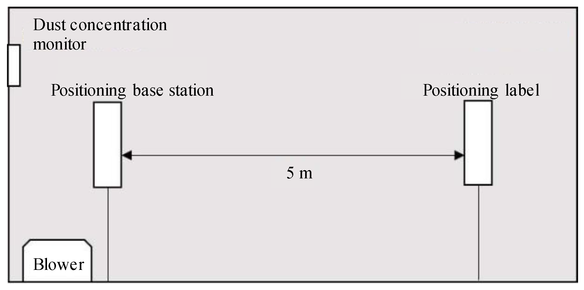
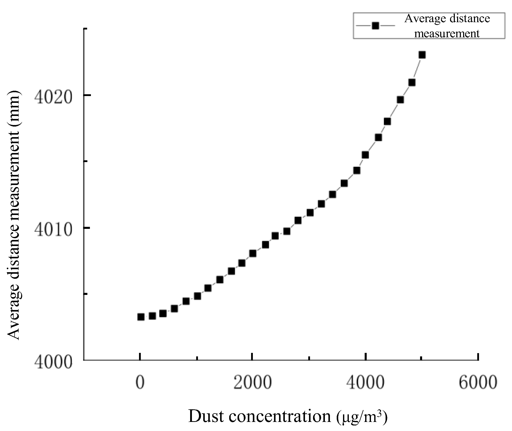
4.2. Effect of Dust Concentration

The dust produced in the operation project of coal mine heading face is mainly rock dust and coal dust. Due to the characteristics of the tunneling process, the process of coal rock crushing will produce a large amount of dust, accounting for about 80% [21] of the total number of dust, which is the main source of dust generation. In addition, there is dust generated by the process of coal rock crushing caused by factors such as collapse impact and transshipment friction, as well as secondary dust generated by ventilation operations [22]. The working environment of the positioning scheme designed in this paper is exposed to the influence of serious dust, and the dust concentration is an important factor affecting the accuracy of the system.
In order to explore the influence of dust concentration on the positioning accuracy of ultra-wideband positioning system, a regular cuboid confined space is set up to simulate the change of dust concentration in the local space of coal mine. The experimental environment is shown in Figure 11.
The allowable limit value of dust concentration in coal mine operations is 5000 μg/m3. Generally, the dust concentration is between 1000 μg/m3 and 3000 μg/m3. Therefore, the reading gradient of dust concentration in the experiment is increased to 5000 μg/m3. To obtain this information one must keep the position of the positioning base station and the positioning label unchanged, control the dust concentration according to the experimental environment, blow into the experimental space with a blower, read and record the dust concentration detector after the indication is stable, read 10 times every 10 s, and take the average value and record. Finally, the change of location and ranging data with the increase in dust concentration is obtained, as shown in Figure 12.
The data analysis shows that with the increase in dust concentration, the ranging error of ranging module increases, and the error growth rate increases with the increase in dust concentration. In the limited range of dust concentration in the coal mine excavation workplace, the influence of dust concentration on the ultra-wideband ranging module is small. The common dust concentration in the excavation face is not more than 3000 μg/m3. Under this condition, the positioning ranging error of 8 m is less than 11.28 mm. According to the principle of error accumulation of optical path influence, the positioning ranging error at 48 m is less than 67.68 mm, and the error level is low.
Therefore, as long as the dust concentration meets the requirements of safety regulations, the influence of dust concentration on the precision and accuracy of ultra-wideband positioning system can be effectively controlled. In the actual working process of the coal mine tunneling face, the positioning system has good anti-dust interference performance and can effectively maintain good system positioning accuracy.

4.3. Mutual Interference Effects of Ultra-Wideband Equipment

The ultra-wideband equipment itself has a strong anti-interference ability, and the equipment used in this system has an anti-interference optimization algorithm and a master-slave base station working mode switching function. However, the positioning scheme and positioning performance requirements of the system determine that the system equipment needs to be coordinated [23,24]. An operation is still needed to verify its anti-interference performance through control variable experiments.
Prepare three ultra-wideband positioning base stations and three positioning tags, select one of them, calibrate its relative position, turn it on, and start ranging reading; after 90 s, the remaining two base stations are opened and randomly placed around the calibration base station. After 90 s, the remaining two tags are opened and randomly placed around the calibration tags for ranging reading and storage. The experimental ranging values are shown in Figure 13.
The analysis of the above figure shows that the error analysis values of the three groups of data in the three time periods are very different, and the data analysis values of different groups have no cross-order of magnitude difference. The data line chart is smooth, the dynamic characteristics are stable, and the data has no obvious accuracy and precision index difference, indicating that there is no obvious interaction between the system equipment.

5. Solution Experiment and Accuracy Evaluation

5.1. Positioning System Positioning Accuracy Evaluation Standard

The absolute error and the mean value of the absolute error in the X, Y, and Z axis directions are used as the standard to evaluate the positioning accuracy. The standard deviation of the solution in the X, Y, and Z axis is used as the standard for evaluating the positioning precision.
The calculation formula of the absolute error eXai, eYai, eZai is
e X a i = L x i L x t ,
e Y a i = L y i L y t ,
e Z a i = L z i L z t ,
In the formula:
( L x i , L y i , L z i ) are the coordinates obtained by the i-th solution;
( L x t , L y t , L z t ) are the true coordinates of the point.
To solve the mean absolute error e ¯ X a i , e ¯ Y a i , e ¯ Z a i , the calculation formula is
e ¯ X a i = i = 1 n e X a i n ,
e ¯ Y a i = i = 1 n e Y a i n ,
e ¯ Z a i = i = 1 n e Z a i n ,
In the formula:
n is the number of system solutions.
The SDX, SDY, and SDZ calculation formulas for the standard deviation of the X, Y, and Z axis are:
S D X = i = 1 n ( L x i L ^ x ) 2 n ,
S D Y = i = 1 n ( L y i L ^ y ) 2 n ,
S D Z = i = 1 n ( L z i L ^ z ) 2 n ,
In the formula:
( L ^ x ,   L ^ Y ,   L ^ z ) is the reference value for the coordinate solution of the point, which is generally the arithmetic average of the solved coordinates for this group of experiments.
Combining the results of the above formulas, the value of the standard deviation of the solved 3D can be obtained:
S D T = S D X 2 + S D Y 2 + S D Z 2
According to the performance requirements of the ultra-wideband positioning system of the cutting head, combined with the three-dimensional positioning principle of the ultra-wideband positioning technology, the system positioning solution deviation should not be greater than 200 mm, and the standard deviation of the settlement data should not be greater than 50 mm.

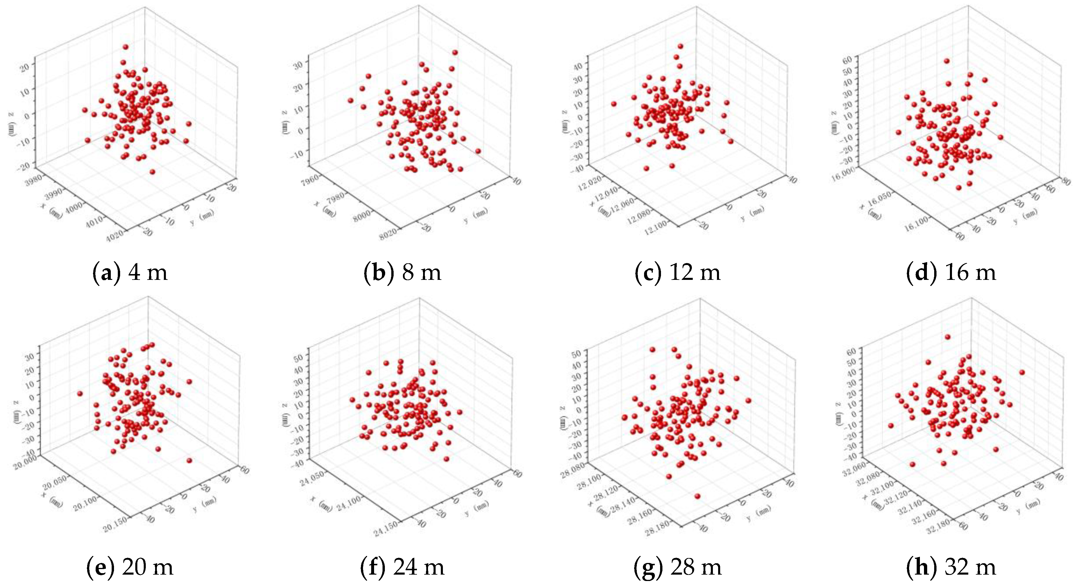
5.2. Dynamic Solution Experiment and Accuracy Evaluation Results

Based on the simulation experiment platform of ultra-wideband positioning system of cutting head, the dynamic positioning accuracy of ultra-wideband positioning system of cutting head is set up to analyze and evaluate the accuracy of positioning system. The experimental simulation experiment distance is set from 4 m to 32 m, each 4 m group, a total of eight groups. Three positioning base stations and their position fixing plates, three positioning tags and their position fixing plates, fuselage simulation brackets, and multi-motion joint trolleys were used to complete the dynamic experiment, and the experimental scene was shown in Figure 4. In experiments at different distances, we kept the spatial position of the center point of the front end of the fuselage simulation bracket unmoving. That is, the solution calibration point is used as the anchor point, placing the anchor point at the distance reference position of each ranging group, within a period of 2 min, the stance of the bracket was changed at a speed not higher than that in the dynamic ranging experiment, the positioning position solution data was captured, and the scatter plot was drawn as shown in Figure 14.
Observing the above three-dimensional scatter plot, it can be seen that the fluctuation range of the solution coordinates is better in the normal use range of the positioning system, the solution deviation belongs to the normal distribution category, the absolute error of the average value of the 3D coordinate data is small, and the precision and accuracy of the system positioning and solving data are high.
Based on the accuracy evaluation standard of the positioning system, the absolute error, the mean absolute error, and the standard deviation are obtained, and the specific evaluation results are shown in Table 1.
In order to facilitate the intuitive analysis of the positioning accuracy and precision of the UWB positioning system, a three-dimensional histogram of the solution accuracy is drawn according to the accuracy evaluation results of the dynamic solution experiment, as shown in Figure 15.
From the absolute error and standard deviation level of the experimental results, it can be seen that the system dynamic positioning solution accuracy is good, the gain of the X-axis dynamic solution deviation increases with distance, and the error is less than 150 mm at 32 m. The gain of Y- and Z-axis dynamic solution deviation with increasing distance is not obvious, and the error is less than 50 mm at 32 m; The comprehensive 3D dynamic solution deviation is less than 170 mm, and the deviation is concentrated in the X-axis direction, which has little impact on the accuracy of the truncated section, the system meets the requirements of the system’s dynamic positioning accuracy, and the standard deviation of the solution data is maintained within 30 mm, which meets the requirements of the system’s dynamic positioning precision.

6. Conclusions

A new positioning system of cutting head based on ultra-wideband positioning technology is proposed, which abandons the complex solution logic of step-by-step fusion solution in different coordinate systems in two steps in traditional cutting head positioning technology. The cutting head is positioned directly through the roadway reference coordinate system, which can eliminate the system solution error caused through the transformation of different spatial coordinate systems.
Combined with the field working conditions, the simulation experiment is set up to analyze the anti-interference of positioning accuracy, and the influence degree of three typical influencing factors on the positioning accuracy is obtained. The results show that the wave transmission of the acrylic plate and the wood plate is good, and the ranging error is always maintained within 50 mm, which will not affect the normal accuracy level of the system. The ranging error of aluminum plate and other metal plates can reach up to 1000 mm, which has a great influence on the positioning accuracy. Plastic materials such as acrylic should be preferred for the packaging shell of positioning system. The normal dust concentration has no significant effect on the positioning accuracy. The ultra-wideband positioning system of the cutting head has good anti-interference performance and can effectively maintain good system positioning accuracy when multiple devices work together.
The experimental results of the dynamic solution of the positioning accuracy of the ultra-wideband positioning system of the cutter head show that: The dynamic calculation accuracy of the ultra-wideband positioning system is high. The mean value of the three-dimensional absolute error is less than 170 mm, and the error is mainly located in the X-axis, which has little effect on the section forming accuracy. The mean value of the single-axis absolute error is less than 50 mm, and the standard deviation of the calculated data is less than 30 mm. The dynamic positioning accuracy and precision of the system meet the expected requirements.

Author Contributions

Conceptualization, H.M. and N.M.; methodology, H.M.; software, H.M. and Y.H; validation, H.Z. and H.M.; formal analysis, H.M.; investigation, Z.Y.; data curation, H.Z. and Y.H; writing—original draft preparation, H.M. and H.Z; writing—review and editing, K.Y. and H.Z; visualization, K.Y. and Y.H.; supervision, H.M. All authors have read and agreed to the published version of the manuscript.

Funding

This research received no external funding.

Data Availability Statement

The data can be provided if necessary.

Conflicts of Interest

The authors declare no conflict of interest.

References

  1. Wang, G.F.; Liu, F.; Meng, X.J.; Fan, J.; Wu, Q.; Ren, H.; Pang, Y.; Xu, Y.; Zhao, G.; Zhang, D.; et al. Research and practice on intelligent coal mine construction (primary stage). Coal Sci. Technol. 2019, 47, 1–36. [Google Scholar]
  2. Wan, J.C.; Zhang, X.H.; Zhang, C.; Yang, W.; Lei, M.; Du, Y.; Dong, Z. Vision and Inertial Navigation Combined-Based Pose Measurement Method of Cantilever Roadheader. Sustainability 2023, 15, 4018. [Google Scholar] [CrossRef]
  3. Yang, J.J.; Zhang, Q.; Wang, C.; Chang, B.; Wang, X.; Ge, S.; Wu, M. Status and development of robotization research on roadheader for coal mines. J. China Coal Soc. 2020, 45, 2995–3005. [Google Scholar]
  4. Rycroft, M.J. Understanding GPS. Principles and applications. J. Atmos. Sol. Terr. Phys. 1997, 59, 598–599. [Google Scholar] [CrossRef]
  5. Yang, W.; Zhang, X.; Ma, H.; Zhang, G. Laser Beams-Based Localization Methods for Boom-Type Roadheader Using Underground Camera Non-Uniform Blur Model. IEEE Access 2020, 8, 190327–190341. [Google Scholar] [CrossRef]
  6. Adam, H.; Jaroslaw, J. Automatic control of roadheader cutting head speed and load torque. IOP Conf. Ser. Earth Environ. Sci. 2020, 609, 012081. [Google Scholar]
  7. Bartoszek, S.; Stankiewicz, K.; Kost, G.; Ćwikła, G.; Dyczko, A. Research on Ultrasonic Transducers to Accurately Determine Distances in a Coal Mine Conditions. Energies 2021, 14, 2532. [Google Scholar] [CrossRef]
  8. Want, R.; Hopper, A.; Falcão, V.; Gibbons, J. The active badge location system. ACM Trans. Inf. Syst. 1992, 10, 91–102. [Google Scholar] [CrossRef]
  9. Zhao, J.X.; Yang, W.J.; Zhang, X.H.; Du, Y.Y.; Zhang, C. Study on accurate positioning method and its visual measurement technology of cantilever roadheader underground. Coal Sci. Technol. 2021, 49, 192–201. [Google Scholar]
  10. Zhang, M.; Lyu, F.; Fu, S.; Cai, X.; Zong, K.; Wu, M. Study on the pitch angle control of a robotized hydraulic drive roadheader using different control methods. J. Mech. Sci. Technol. 2018, 32, 4893–4901. [Google Scholar] [CrossRef]
  11. Cheluszka, P.; Jagiea-Zajc, A. Determining the position of pick holders on the side surface of the working unit of the cutting machine in the robotic technology of their assembly. IOP Conf. Ser. Earth Environ. Sci. 2019, 261, 012003. [Google Scholar] [CrossRef]
  12. Du, Y.X. Study on the Pose Perception and Positioning Mechanism of Boom-Type Roadheader in Mines; China University of Mining and Technology: Xuzhou, China, 2019. [Google Scholar]
  13. Wu, M.; Shen, Y.; Ji, X.D.; Wang, P.J.; Jiang, H.; Zheng, W.X.; Li, Y. Trajectory and deviation perception method of boom-type roadheader. J. China Coal Soc. 2021, 46, 2046–2056. [Google Scholar]
  14. Wang, B.K. Current status and trend analysis of readway driving technology and equipment in coal mine. Coal Sci. Technol. 2020, 48, 1–11. [Google Scholar]
  15. Yang, W.J.; Zhang, X.H.; Ma, H.W.; Zhang, G.-M. Infrared LEDs-Based Pose Estimation with Underground Camera Model for Boom-Type Roadheader in Coal Mining. IEEE Access 2019, 7, 33698–33712. [Google Scholar] [CrossRef]
  16. Olivart i Llop, J.M.; Moreno-Salinas, D.; Sánchez, J. Full Real-Time Positioning and Attitude System Based on GNSS-RTK Technology. Sustainability 2020, 12, 9796. [Google Scholar] [CrossRef]
  17. Eric Calais, J. Bernard Minster, Michelle Hofton. Ionospheric signature of surface mine blasts from Global Positioning System measurements. Geophys. J. Int. 1998, 132. [Google Scholar]
  18. Wang, S.Y.; Ma, D.C.; Ren, Z.; Wu, M. A multi-objective optimization method for cantilever roadheader section forming trajectory. Chin. J. Sci. Instrum. 2021, 41, 183–192. [Google Scholar]
  19. Tian, Y.; Yang, X.; Yang, J.; Mao, K.K.; Yao, Y.J. Evolution dynamic of intelligent construction strategy of coal mine enterprises in China. Heliyon 2022, 8, e10933. [Google Scholar] [CrossRef]
  20. Zang, X.H.; Yang, W.J.; Xue, X.S.; Zhang, C.; Wang, J.; Mao, Q.; Lei, M.; Du, Y.; Ma, H.; Zhao, Y. Challenges and developing of the intelligent remote controlon roadheaders in coal mine. J. China Coal Soc. 2022, 47, 579–597. [Google Scholar]
  21. Xu, M.G.; Liu, X.K.; Wen, X.Q. Full-mechanized excavation face efficient sprinkler & dust fall system. J. Hunan Univ. Sci. Technol. 2015, 30, 1–7. [Google Scholar]
  22. Piotr, C. Optimization of the Cutting Process Parameters to Ensure High Efficiency of Drilling Tunnels and Use the Technical Potential of the Boom-Type Roadheader. Energies 2020, 13, 6597. [Google Scholar]
  23. Yang, J.; Zhang, G.; Huang, Z.; Ye, Y.; Ma, B.; Wang, Y. Research on position and orientation measurement method for roadheader based on vision INS. In Proceedings of the International Conference on Optical Instruments and Technology 2017: Optoelectronic Measurement Technology and System, Beijing, China, 28–30 October 2017. Society of Photo-Optical Instrumentation Engineers Conference Series. [Google Scholar]
  24. Orteu, J.; Catalina, J.; Devy, M. Perception for a roadheader in automatic selective cutting operation. In Proceedings of the IEEE International Conference on Robotics and Automation, Nice, France, 12–14 May 1992; Volume 5, pp. 626–632. [Google Scholar]
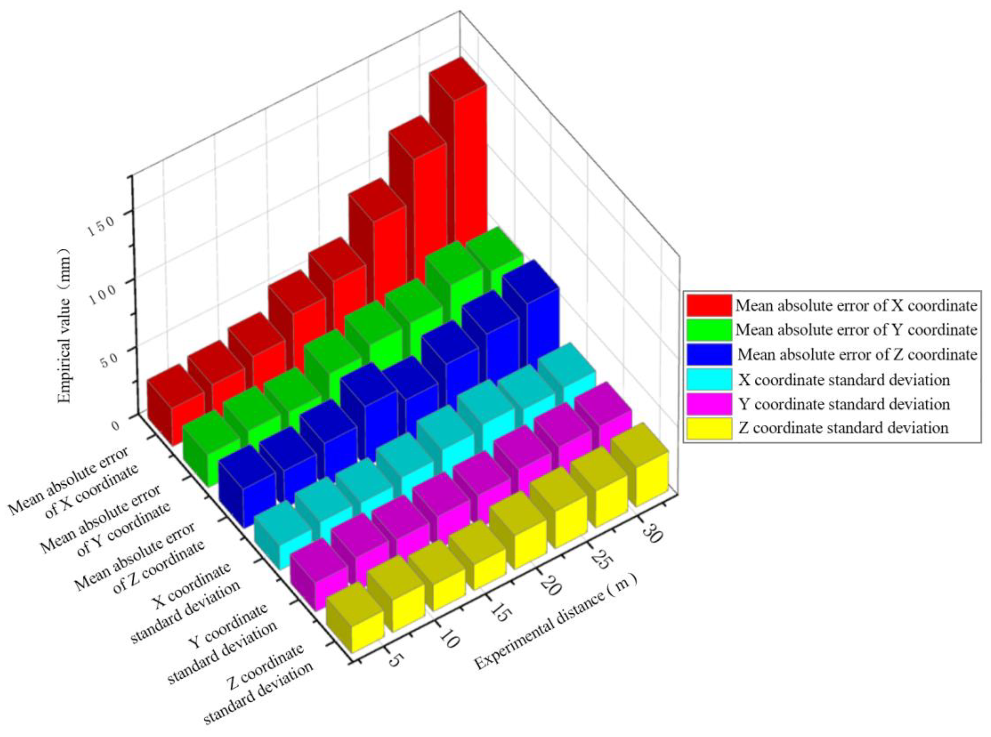
Figure 1. Simplified model of cutting part motion.
Processes 11 02534 g001
Figure 2. Schematic diagram of cutting head positioning scheme.
Processes 11 02534 g002
Figure 3. Flow chart of an ultra-wideband positioning system for cutting head.
Processes 11 02534 g003
Figure 4. Schematic diagram of the overall experimental setup.
Processes 11 02534 g004
Figure 5. Layout dimension diagram of UWB positioning base stations.
Processes 11 02534 g005
Figure 6. Layout dimension diagram of UWB positioning labels.
Processes 11 02534 g006
Figure 7. Schematic diagram of the experimental setup for the impact of obstructing objects.
Processes 11 02534 g007
Figure 8. Experimental board.
Processes 11 02534 g008
Figure 9. Error-values of obstructing object impact experiment. (a) Error values of acrylic board. (b) Error values of wooden board.
Processes 11 02534 g009
Figure 10. Measured distance values of aluminum plate obstruction experiment.
Processes 11 02534 g010
Figure 11. Schematic diagram of the experimental setup for the effect of dust concentration.
Processes 11 02534 g011
Figure 12. System ranging error under different dust concentrations.
Processes 11 02534 g012
Figure 13. The equipment interference experiment changes the ranging value with time.
Processes 11 02534 g013
Figure 14. Scatter plot of positioning values.
Processes 11 02534 g014
Figure 15. Three-dimensional histogram of dynamic solution experimental accuracy.
Processes 11 02534 g015
Table 1. Dynamic solution experiment precision evaluation table.
Experimental Distance (mm) e ¯ X a i (mm) e ¯ Y a i (mm) e ¯ Z a i (mm) S D X (mm) S D Y (mm) S D Z
428.3224.6529.6518.6221.5420.04
830.6526.9327.8420.6524.6624.25
1236.2125.6332.7919.4522.6320.06
1652.3138.6240.6322.7824.2319.47
2061.3644.5734.2327.8624.5425.45
2489.6245.6945.3231.4228.3128.00
28120.3448.3242.3227.1229.6227.61
32147.9549.5249.3428.0129.4629.56
Disclaimer/Publisher’s Note: The statements, opinions and data contained in all publications are solely those of the individual author(s) and contributor(s) and not of MDPI and/or the editor(s). MDPI and/or the editor(s) disclaim responsibility for any injury to people or property resulting from any ideas, methods, instructions or products referred to in the content.

