Abstract
Additive manufacturing (AM) technologies enable the production of customized and personalized medical devices that facilitate users’ comfort and rehabilitation requirements according to their individual conditions. The concept of a tailor-made orthopedic device addresses the accelerated recovery and comfort of the patient through the utilization of personalized rehabilitation equipment. Direct modeling, with an increasing number of approaches and prototypes, has provided many successful results until now. The modeling procedure for 3D-printed orthoses has emerged as the execution of steady and continuous tasks with several design selection criteria, such as cutting, thickening the surface, and engraving the shell of the orthosis. This publication takes into consideration the aforementioned criteria and proposes the creation of a holistic methodology and automated computational design process for the customization of orthotic assistive devices, considering aspects such as material properties, manufacturing limitations, recycling, and patients’ requirements. This proposal leads to the designing and manufacturing of a wrist orthopedic device based on reverse engineering, Design for AM (DfAM), and Design for Recycling (DfR) principles. The proposed methodology can be adjusted for different limbs. A dual-material approach was attained utilizing rigid, mechanically enhanced feedstock material and soft elastic material with reduced skin irritation risks to achieve both mechanical requirements and adequate cushioning for user comfort during rehabilitation. Recyclable thermoplastic matrices were selected, which also allow for the option to create washable devices for product life extension. Then, 3D scanning procedures were implemented to acquire the initial anatomic measurements for the design of the WHO and ensure and assess the dimensional accuracy of the final product. Physical mechanical testing was implemented to evaluate the WHO’s mechanical behavior and verify its functionality during basic wrist movements. The extracted dimensional data for the two main orthosis components that indicated approximately 50% and 25% of the tolerance values, respectively, were within the range (−0.1 mm, 0.1 mm).
1. Introduction
Orthopedic devices, commonly known as splints, braces, or orthoses, functionally assist the musculoskeletal system of a limb by providing supportive weight balance to correct deformities and assist or restrict motion, similar to protective casts [1,2]. These devices are used to treat dysfunctions or injuries and can be divided into three categories based on the affected joints of the body: spinal orthopedic devices (e.g., lumbar–sacral orthoses or LSOs), lower limb orthopedic devices (e.g., ankle–foot orthoses or AFOs), and upper limb orthopedic devices (e.g., wrist–hand orthoses or WHOs) [1,3,4]. WHOs are employed to treat conditions such as fractures when immobilization is necessary, congenital deformities, and chronically degenerating orthopedic conditions. The present study primarily focuses on WHOs developed for fracture immobilization. Conventional splinting processes are skill-dependent and irreversible, and patient satisfaction levels during rehabilitation are typically lowered by the heavy structure and poor ventilation of WHOs [5]. The primary materials employed in traditional fracture immobilization treatments are plaster or fiberglass, together with a soft inner cotton layer. Due to their lack of breathability and water-resistant properties, these materials may cause skin irritation and, in some cases, lead to cutaneous complications [6,7]. In addition, conventional WHOs are bulky and unsightly, thereby causing significant discomfort to patients in rehabilitation in terms of thermal comfort, hygienic maintenance, and aesthetic appeal [5,6]. Furthermore, the effectiveness of the splint-fitting process is highly dependent on the clinician’s skill and experience due to the irreversible nature of the materials and the use of body-based contact models [5,7]. The bottom mold of a cast is generated from the surface shapes of injured limbs, with patients suffering additional mechanical pressures during the manufacturing process [7]. As a result, the level of patient satisfaction during the treatment process can greatly vary depending on the clinician’s expertise in splinting [5,7,8,9]. Inexperienced practitioners may cause more discomfort or lead to inadequate immobilization [5].
In recent years, the capacity of 3D printing to enable the mass customization of orthoses and improve patient treatment satisfaction has been extensively discussed in the field of orthopedic and rehabilitation practices [7,10,11,12,13]. Studies on 3D-printed orthoses with lightweight, well-ventilated, waterproof, and aesthetically pleasing features have effectively addressed the shortcomings of traditional orthoses [5,6,7,9,11,13]. The sustainable adoption of 3D printing for customized rehabilitation has been further expanded to encompass technical diversity, including structural optimization, environmental safety, and product compatibility, highlighting the integration of these factors in a holistic approach [1]. Furthermore, 3D printing technology has greatly benefited the production of orthoses by enabling the creation of highly intricate and personalized orthoses at a relatively low cost [13].
The common workflow methodology for the production of a 3D-printed orthosis is analyzed as follows [14,15,16]:
- The orthosis mesh model is acquired from the surface of the patient’s affected limb by means of 3D scanning.
- The orthosis model is designed by means of computer-aided design (CAD) software tools and exportation of fabrication data.
- The physical orthosis is fabricated by means of slicing software and a 3D printing device.
Despite the advantages of the aforementioned digitization processes, optimization steps towards a holistic approach for the creation of orthoses are still required. Common CAD modeling techniques involve numerous steps (e.g., a hollowed pattern design, Boolean operations, etc.) with limited reversibility, and the total production time required highly depends on the CAD skills of the operators, who are usually healthcare professionals [5]. Whereas clinicians are required to apply the necessary interdisciplinary skills (i.e., design and medical knowledge) to a patient’s unique anatomical features and needs, the integration of a flexible CAD interface in the splinting process that facilitates the interaction and feedback loop between the former and the latter has not been investigated yet to the best of the authors’ knowledge. Furthermore, it is important to consider the entire life cycle of the final product, including its production, use, and disposal, integrating segregation aspects that allow for material recycling [17]. A variety of factors related to the material properties, such as their biocompatibility, sterilizability, strength, and durability, together with their leaching behavior, must also be taken into consideration [18]. The leaching behavior of nanocomposite materials in solutions that simulate washing and/or use conditions can provide the information necessary to mitigate any potential risks ensuring the development of wearable devices that are both functional and safe for users [19]. Additionally, it is essential for the manufactured commercial products to be evaluated for their skin-sensitizing potential. Skin sensitization consists of a type IV hypersensitivity response triggered after repeated dermal exposure to a possible allergenic substance in susceptible individuals. In this context, the evaluation of skin sensitization is based on ISO 10993-10:2013 [20]. Most of these methods evaluate the ability of chemicals to upregulate the expression of dendritic cell activation markers or/and the expression levels of proinflammatory cytokines as mediators of several inflammatory reactions [21]. In the present study, our developed materials were tested in vitro in order to evaluate the sensitizing potential of these materials by quantifying the release of proinflammatory cytokines in the cell culture medium. The expression of tumor necrosis factor-α (TNF-α) and interleukin-18 (IL-18, also known as interferon-gamma inducing factor), both mediators of immune and inflammatory responses, was quantified.
The present study aims to develop an integrative methodology for a precompiled customization system by means of material selection and an interactive CAD interface for 3D printed WHOs. The proposed methodology allows clinicians to verify the state of the WHO production at every stage, thereby facilitating the adjustment of input content or other parameters. In this scope, the developed WHO capitalizes on reverse engineering (i.e., 3D scanning) and computational/parametric design tools (i.e., visual programming and FEA) for surface data acquisition and semi-automated design customization and validation, combined with fused filament fabrication (FFF) 3D printing and material design/analysis for optimum fitting and functional properties. The parametric environment enables the interactive selection of the WHO’s thickness and lattice pattern according to each incident’s support requirements, as well as its segregation into multiple functional parts for efficient 3D printing (DfAM) [22]. More specifically, the integration of dual-material printing properties allows for different functionalities in selected areas (namely rigid or flexible parts) and/or non-irritant skin properties on the surface in contact with the patient’s limb. Furthermore, in terms of recycling (DfR) [17], the proposed design methodology capitalizes on recyclable materials, while features that facilitate the sorting of the materials are integrated, considering the printing orientation of the parts to avoid the fusion of distinct layers of materials. Additionally, the presented WHO design supports the incorporation of near-field communication (NFC) and radio frequency identification (RFID) labels for storage and immediate access to a range of information connected with the WHO, namely the user guide, maintenance instructions, data concerning the materials used, and environmental impact.
The precompiled customization system presented Is applicable for WHOs aimed at the immobilization of distal radial/ulnar and carpal fractures. Pathological/open fractures and fractures requiring internal fixation remain, therefore, out of the scope of the present study [11].
2. Materials and Methods
2.1. Materials
The materials selected for the WHO’s manufacturing are recyclable thermoplastics that incorporate the desired performance properties. Custom Tritan copolyester (CPE) TX1501 with chopped carbon fibers (CFs) and thermoplastic polyurethane (TPU) were selected to be utilized for the outer and inner parts of the WHO, respectively, as the beneficial ability of TX1501-CFs to produce lightweight parts with high fatigue strength facilitates the structural properties of the outer component, while the elastic nature of TPU augurs comfort during rehabilitation.
For the establishment of the optimum composition of TX1501 in CF, two different cases of CF concentration were examined: TX1501 with 7.3% CF and TX1501 with 14.2% CF, considering not only the mechanical enhancement of the final part but the processability through the fused filament fabrication (FFF) process. Interdependent custom parameterization tests were realized to evaluate the printability of each material in terms of varying the main printing parameters, namely the printing speed, extrusion temperature, and retraction distance, in order to select the material that exhibits adequate printability and an optimal combination of printing parameters. Two types of printing tests for the evaluation of the materials’ printability performance were generated by varying (a) one single printing parameter or (b) two printing parameters at the same time. When one parameter was tested, the value increased in each printing region while moving horizontally, whereas when two parameters were tested at once, the value of one parameter value increased while moving horizontally, and the value of the second parameter increased while moving downwards, as is depicted in Figure 1. Table 1 shows the optimum printing parameters selected for TX1501 with 7.3%CFs.
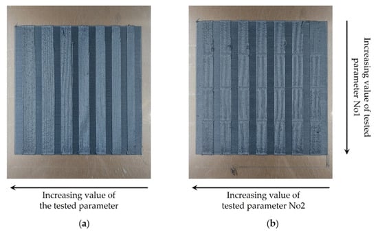
Figure 1.
Samples of the printability tests. (a) Printing sample with one varying process parameter. (b) Printing sample with two varying process parameters.

Table 1.
TX1501 with 7.3% CFs 3D printing parameters.
2.2. Workflow Description
The workflow implemented for the development of the presented personalized WHO from limb data acquisition to the manufacturing process is illustrated in the following Figure 2.
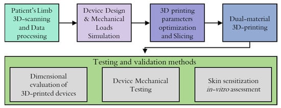
Figure 2.
Workflow followed for the development of the WHO.
The process of creating the orthotic began with limb data acquisition through 3D scanning. The retrieved point cloud model was processed using CAD software, considering the proportions of the patient’s limb, and a surface was created in order to be used as a base geometry to further develop the WHO design. The optimization and finalization of WHO design were supported by FEA tools in an effort to predict the influence of applied loads from patients’ movements.
Prior to the manufacturing of the designed model, a printing optimization procedure was followed, where the optimum printing parameters and slicing settings were determined in order to mitigate material waste due to misprints and acquire high-resolution components, especially when new types of materials or recycled materials were utilized for the manufacturing process. Then, the 3D printing was realized utilizing the dual extrusion of materials, and finally, the manufactured WHO was subjected to testing procedures for the physical validation of certain product requirements, namely its mechanical strength, dimensional evaluation, and skin contact compatibility for daily use.
2.3. 3D Scanning of Patient’s Limb: Surface Data Acquisition
The acquisition of patients’ limb topographic data is required for the development of fully personalized splints that are better suited to the demands of individual injury cases, thus shortening healing times and improving restorative quality. The process for the development of an accurate, digitized custom splint design regarding data retrieval and utilization can be summarized in two consecutive steps: the data acquisition of the patient’s upper extremity’s skin surface topography and the analysis and manipulation of the acquired point cloud into an exploitable form. The latter usually consists of (i) cleaning the point cloud of noise and duplicate points, (ii) reducing the overall number of points without loss of quality, (iii) converting the point cloud to a tessellated mesh, (iv) repairing voids, gaps, and imperfections in the mesh, leading to a watertight model, and (v) converting the model to a 3D-printing-compatible format (e.g., STL). As soon as the aforementioned steps were carried out, the digital model was used as a foundation for the development of the corresponding digital model of the splint.
In order to map the process required for wrist 3D scanning, taking into consideration the patient’s comfort while ensuring accurate data acquisition, the following workflow has been established:
- Initially, the injury or fracture is visually assessed.
- The splint requirements are outlined based on the injury assessment.
- In the presence of a plaster cast, removal is put into consideration.
- If applicable, the cast is removed for direct scanning.
- If removal is not applicable, the geometry of the contralateral limb is imprinted due to symmetry.
- A series of measurements of main limb dimensions are performed, which are to be used as reference points to enhance measurement accuracy and facilitate 3D model creation. These typically include relevant lengths and circumferences of the area of interest, such as the distance between the wrist and the elbow, the length of the arm, circumferences of the palm, the wrist, and the elbow, as well as fixed points, such as the elbow and wrist joints.
- Limb positioning: Several possible positioning strategies exist, depending, for example, on the patient’s injury. Generally, the options considered in similar cases are the following:
- The arm is prefixed forward, with the forearm raised at 90° with respect to the former and perpendicular to the ground. The hand is positioned in a neutral position, aligning with the forearm.
- The arm is prefixed forward, with the forearm raised at 90° with respect to the former and parallel to the ground. The hand is positioned in a neutral position, aligning with the forearm.
In each case, a slight inclination of the wrist is acceptable if deemed necessary. Depending on the type of scanner, circular navigation targets may be required to be placed in the vicinity or on the surface of the limb. - Acquisition phase: The patient is required to remain in the established position throughout the duration of the acquisition process so that the scanning process can yield as accurate results as possible.
A major challenge during the scanning process is ensuring that the patient maintains stillness in the established position throughout the duration of data acquisition, especially in case their particular injury causes discomfort, as can be observed in Figure 3. In some cases, scaffolding to support the limb may be required. In every case, the scanning equipment operator is obligated to complete the procedure in the minimum time possible while being mindful so as to avoid loss of quality. An additional issue encountered during this process refers to the geometry acquisition of the patient’s fingers (Figure 3). Spacing between digits needs to be clear in order to produce a distinguishable geometry. In most splint design cases, this information is irrelevant to produce the brace, though, in instances where capturing the geometry of the fingers is necessary, careful consideration must be applied, especially around the area of the thumb. On the occasion where the fingers’ area is of significant importance to the final design, a set of smaller lenses can be attached to the scanning equipment, depending on the scanner model. Figure 4 provides a characteristic example of the 3D model of a scanned arm. In the presented case, a Creaform HandySCAN 700 laser 3D scanner (Creaform, Lévis, Canada) was utilized to imprint the arm geometry. The scanner was selected due to its nominal resolution of 50 μm (with accuracy up to 30 μm) [23] and high acquisition speed, which allowed for the fast completion of the procedure. Due to compatibility reasons, the VXElements suite was employed; specifically, we used VXscan for scanning and VXmodel for the initial editing of the digital files.
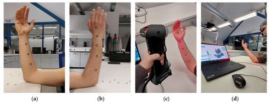
Figure 3.
3D scanning of patient’s limb. (a) Limb front side; (b) limb back side. (c) Limb 3D scanning sequence. (d) User interface during scanning sequence.
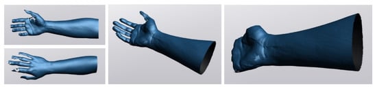
Figure 4.
Digital recreation of 3D-scanned limb model.
2.4. Computational Design and FEA Optimization Workflow for a Personalized WHO
A programmable modeling tool was developed in the Grasshopper 1.0.0007 development platform and integrated with the Rhinoceros 3D 7 software. This precompiled customization tool enabled the interactive generation of variant 3D-printable WHO models by means of visual programming and the clinician’s feedback on selected input parameters. The modeling and optimization process is divided into 7 steps, capitalizing on DfAM and DfR strategies for:
- Simultaneous dual-material printing considering structural integrity, immobilization, and tactile comfort, as well as detachment for sorting and recycling;
- On-demand thickness and lattice structure density adjustments;
- The integration of advanced functionalities (i.e., IoT) by means of embedded NFC and RFID tags,
- Assembly/disassembly strategies to minimize complications during fabrication;
- FEA validation in Dassault Systèmes SOLIDWORKS Professional 2021 software for design optimization in a feedback loop.
Figure 5 outlines the computational design and FEA optimization workflow in steps, as analyzed in the following. In spite of the complexity involved in the described computational workflow, all the design decisions on customizability are only related to the interactive section of global inputs (i.e., Step 1), which mainly require the control of surface inputs, thicknesses, pattern size, etc.
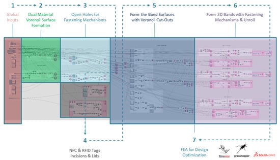
Figure 5.
Outline of computational design and FEA optimization workflow for a personalized WHO.
Step 1 connotates the interactive section of global inputs, showing where clinicians can intervene on crucial design features in collaboration with their patients. The mentioned section allows clinicians to confirm the state of the WHO model at each step. This enables them to make all necessary adjustments to the input content or other parameters and address any issues that may arise during the modeling or fabrication process.
Step 2 involves the retrieval of the principal limb surfaces for the introduction of a hollowed Voronoi tessellation pattern [24]. After the simplification of the 3D-scanned polygon mesh by means of polygon reduction, the mesh is converted into a polysurface. The polysurface is then translated into two principal input surfaces that are employed in all further computational design procedures and lead to the formation of all the WHO sub-components. Based on the approximate dimensions of the principal input surfaces, rectangular XY planar surfaces are created (Figure 6a). A Voronoi pattern is generated on each planar rectangular surface (Figure 6b). Both the number of Voronoi cells and the frame thickness can be parametrically adjusted by the user. The pattern density can be further locally optimized by means of additional centroids and scaling down of the cells. The sharp edges of the Voronoi cell polygons are subsequently smoothed through a filleting feature. The 2D-hollowed Voronoi tessellated surfaces are then morphed to adapt to the principal input surfaces, while two thickness variants are created for assigning dual-material properties to the WHO for immobilization, tactile sensation, and comfort (Figure 6c).
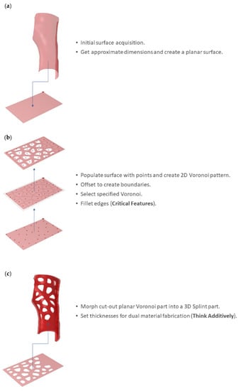
Figure 6.
Dual-material Voronoi surface formation: (a) initial limb surface acquisition and approximation as a rectangular XY planar surface; (b) 2D-hollowed Voronoi tessellation; (c) consideration of dual-material properties for immobilization, tactile sensation, and comfort.
Step 3 involves the creation of the fastening mechanisms’ openings on both dual-material parts (Figure 7). The inner solid part is exploded, and the inner surface is selected. IsoCurves (in the U direction) close to the outer edges of the surfaces are designated. Multiple UV points on the selected IsoCurves are then defined as centroids for the circular profiles of the openings. The circular profiles are extruded based on the normal vectors at the respective UV points. The cylindrical extrusions are then cut out from the dual material parts by means of Boolean difference operations.
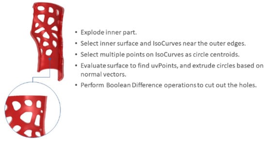
Figure 7.
Opening holes for fastening mechanisms.
Step 4 involves the creation of incisions to embed NFC and RFID tags. The outer parts are exploded, while the outer surfaces are employed for the selection of (a) a UV point as a circular profile centroid aimed for the NFC incision (Figure 8a) and (b) four IsoCurves as guides for a rectangular profile aimed for the RFID incision. The thickness of the aforementioned profiles is assigned. The incisions and the respective lids are formed by means of Boolean operations (Figure 8b), while detailed features (i.e., logotypes) are also created (Figure 8c).
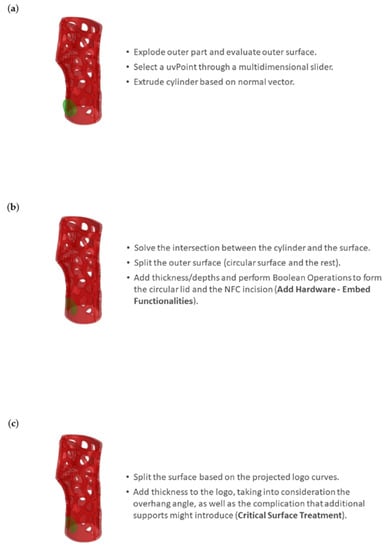
Figure 8.
Integration of NFC tag: (a) evaluation of outer surface for the selection of a UV point as a circular profile centroid aimed for the NFC incision; (b) Boolean operations for the NFC incision and lid formation; and (c) addition of detailed features considering overhang angles.
Step 5 involves the formation of band surfaces for flexible donning and doffing operations (i.e., putting the device on and taking it off). The uppermost outer surfaces are selected for the creation of the band surfaces, and IsoCurves in both the U and V directions are defined. Cut-out rectangular surfaces that form the basis of the bands are then created (Figure 9a). A filtering Python script employing an IF statement is developed To proceed with trimming the rectangular bands based on the Voronoi tessellation and the circular cut-out details (Figure 9b). The intersections between the Voronoi curves and the IsoCurves are then used to trim the edges of the band surfaces. Finally, the circular profiles are projected onto the new trimmed surfaces, and their centroids are defined. The circular curves and their respective centroids are subsequently deployed for the detailed fastening mechanisms (see Step 6). In the present study, the procedure is repeated for the formation of three bands (Figure 9c).
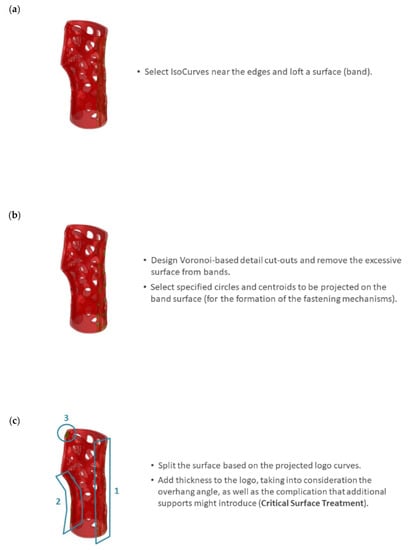
Figure 9.
Band surface formation with Voronoi cut-outs: (a) IsoCurve selection for the formation of rectangular bands; (b) trimming the rectangular bands based on the Voronoi tessellation and the circular cut-out details; and (c) repetition of the procedure for the formation of three bands.
Step 6 includes all necessary processes for the formation of three 3D bands with fastening mechanisms, as well as an unrolling process to minimize complications during fabrication. Firstly, the three trimmed surfaces are offset outwards as solids. For the fastening details, grafted arrays of the circular profiles created in Step 5 are formed based on the normal vectors of the tangent circular profiles’ UV centroids. Then the grafted curves are alternately selected by means of a culling pattern and scaled down. Subsequently, the remaining non-scaled grafted curves are selected based on the inverse culling pattern. The data are then woven and lofted into solid fastening details with a sine wave pattern (Figure 10a). Finally, the wavy fastening details are joined with the bands via Boolean operations. In order to make the intricate bands manufacturable, they are finally unrolled in the XY plane (Figure 10b).
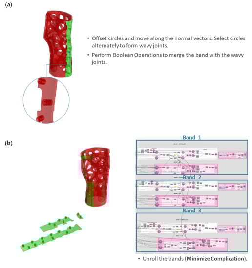
Figure 10.
Formation of 3D bands with fastening mechanisms and unrolling: (a) wavy joints; (b) unrolling of the three bands.
Multiple design variations can be produced by selectively adjusting the global input parameters of the precompiled customization tool, as set in Step 1. For instance, the outer parts’ inner surface is parametrically offset to precisely control the distance between the two material cases, aiming for both robust dual-material attachment and easy detachment for sorting and recycling (Figure 11).
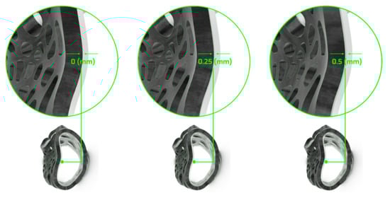
Figure 11.
Variations in dual-material system interaction through parametric control of surface distance.
Furthermore, multiple design variations can be generated by means of (a) scaling the hollowed Voronoi tessellation pattern and (b) increasing/decreasing the outer rigid parts’ thickness. For the purposes of the present study, a Voronoi scaling factor of 0.65 and an outer rigid part thickness of 4 mm were selected after taking into consideration the in-house AM unit fabrication capabilities and the requirement for a robust yet material-efficient structure. The preliminary generated WHO (i.e., main body with two bands) further underwent FEA for static linear analysis (Step 7) in Dassault Systèmes SOLIDWORKS Professional 2021 software to predict the von Mises stresses and the local displacements. The CPE TX1501 and TPU material properties were assigned to the hard and soft WHO components, respectively. Both materials were considered isotropic. For representation purposes (in relation to the physical materials), hard components are depicted in black, and soft components are depicted in transparent off-white. Fixed-boundary conditions were assigned to the base of the WHO. Furthermore, bonded connection properties were assigned to the soft bands and the hard outer subcomponent interface. The WHO geometry was simulated under four load cases: (a) flexion, (b) extension, and (c) radial and (d) ulnar deviation, representing the four wrist movements (Figure 12) [25]. The load values selected from the literature [26,27,28] are presented in Table 2. The load case of 50% was selected as the most representative, as it is assumed that the patient’s muscle strength is reduced and, therefore, not able to exert a 100% load on the WHO during rehabilitation.
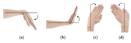
Figure 12.
Types of wrist movements studied through FEA: (a) flexion; (b) extension; (c) radial deviation; (d) ulnar deviation.
Table 2.
Applied load for each tested movement type.
2.5. Slicing and Printing Process
In order to perform dual-material extrusion, a Raise3D Pro2 Plus 3D printer was employed for the manufacturing process, and the printing was realized at ambient temperatures in limited-humidity conditions.
The presented WHO consists of seven parts: two dual-material main components, three TPU fasteners, one TX1501-7.3%CFs lid for the NFC tag, and one TX1501-7.3%CFs lid for the RFID tag. The printing parameters applied during the manufacturing process for each material were determined based on the performance of the materials when being printed on custom parameter-optimizing tests, which is also presented in Section 2.1 for the selection of CF concentrations in TX1501. Figure 13 displays generated printability samples that test different process parameters.
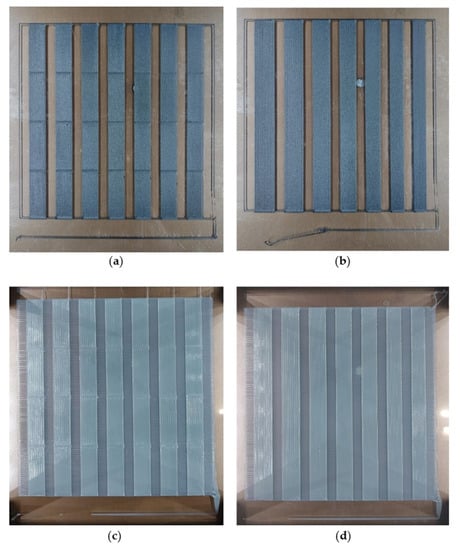
Figure 13.
Samples of printability tests. Material and process parameters tested: (a) TX1501-7.3%CFs, with their first-layer track height and first-layer printing speed; (b) TX1501-7.3%CFs with a first-layer track width; (c) TPU extrusion temperature and printing speed; (d) TPU track width.
The test samples printed for the printability assessment were evaluated with a Leica S9 D stereoscope in order to identify and quantitate potential overfill or underfill defects. Figure 14 and Figure 15 present some examples of overfill and underfill defects detected through the evaluation process of TX1501-7.3%CFs and TPU, respectively. In the case of multiple regions with great printability performance, the ones printed with parameters that minimized printing time, namely, higher values of printing speed, track height, or track width, were preferred.
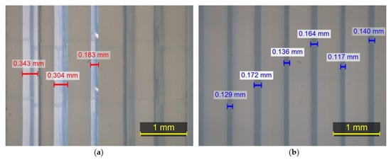
Figure 14.
Images of TPU captured with stereoscope: (a) underfill defects; (b) overfill defects.
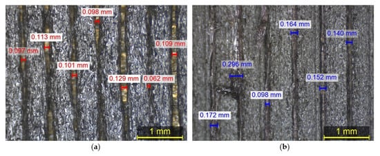
Figure 15.
Images of TX1501-7.3%CFs captured with stereoscope: (a) underfill defects; (b) overfill defects.
Utilizing the optimum parameters derived from the printability tests, the two main parts of the orthopedic device were designed to be printed with a brim on the first layers to facilitate their adhesion with the print bed, as depicted in Figure 16. Moreover, for the 3D printing of the dual-material parts, additional printing settings had to be introduced in order to avoid the intrusion of one material into the other, thus facilitating the obtainment of solid parts without voids at the same time. Thus, a G-Code was generated for the heating of the operating nozzle and cooling of the idle nozzle, and a prime tower (Figure 16) was utilized before the printing of each material to ensure proper material flow. Hence, at every layer before printing with each material, the print head is moved aside to preheat the active nozzle and cool the second one, and as soon as the desired temperatures are reached, one layer of prime tower is created to obtain the proper material flow before starting the printing of the main part. The G-Code utilized for the heating and cooling of the two nozzles is the following:
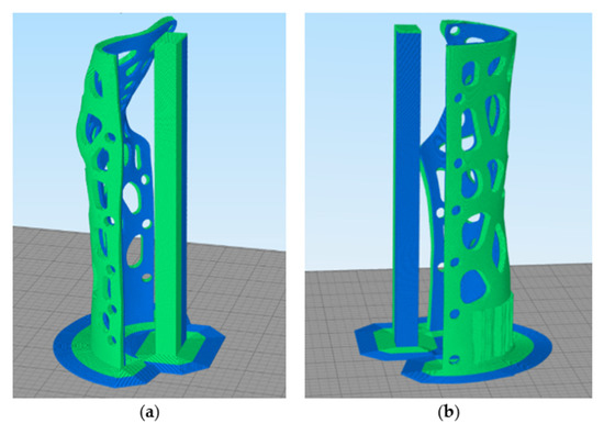
Figure 16.
Printing preview mode of the orthopedic device (Slicing software: Simplify3D 4.1.2): (a) 1st main part; (b) 2nd main part.
- G1 X75 Y150
- {IF NEWTOOL = 0}M104 S238 T1; Cool T1 (TX1501) extruder to 238
- {IF NEWTOOL = 0}M109 S215 T0; Heat T0 (TPU) new active extruder to 215 and wait for it to reach temperature before proceeding
- {IF NEWTOOL = 1}M104 S205 T0; Cool T0 (TPU) to 205
- {IF NEWTOOL = 1}M109 S260 T1; Set T1 (TX1501) Heat T1 to 260
The decision to cool the non-operating nozzle was based on the requirement to mitigate material drips due to high nozzle temperatures. However, the nozzle temperature set for each material while not operating was determined after optimizing the aforementioned requirement to minimize dripping with the need to prevent nozzle clogging due to low hot-end temperatures. Therefore, the temperature values for TX1501-7.3%CFs and TPU when the corresponding nozzle is not operating are 238 and 205 , respectively.
Finally, trials with different x and y nozzle-offset settings were performed to set the optimum nozzle offset distance that facilitates material adhesion without material intersection. The x and y right nozzle offset values correspond to the translation of the axis from the left nozzle coordinate system to the right nozzle coordinate system. Particularly, the x and y right nozzle offsets correspond to the coordinates that Origin OR (of the right nozzle’s coordinate system) has in the left nozzle’s coordinate system XYL (Figure 17). The established values for the x and y right nozzle’s offset are 25.30 mm and −0.60 mm, respectively, achieving ease in detaching the two materials through hand-operated pull trials.
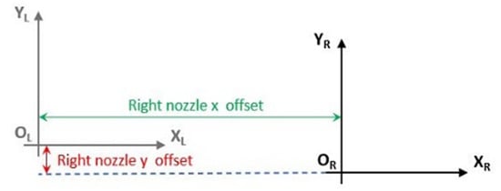
Figure 17.
Display of right nozzle x and y offset values.
2.6. In Vitro Assessment of Skin Sensitization
Prior to in vitro testing, material samples were sterilized by being immersed in 70% ethanol (v/v) overnight, followed by rinsing three times with 1× PBS to eliminate all traces of ethanol. Then, samples were air-dried in a sterile atmosphere before being sterilized for 1 h with ultraviolet light. This phase ensured that any pollutants on the surface were removed to avoid the contamination of the cell cultures.
The sterile samples were immersed in complete DMEM overnight before testing. Hs27 skin cells (human fibroblasts, skin, foreskin) complying with the ISO 10993-5 standard for cytotoxicity testing were purchased from the American Type Culture Collection (ATCC, Manassas, VA, USA) and were grown to confluence in complete DMEM containing 10% FBS and 1% penicillium/streptomycin solution at 37 °C in an incubator with 5% carbon dioxide (CO2). Samples were placed in each well in 12-well plates, followed by direct cell seeding at a seeding number of 15 × 104 cells per well. Subsequently, the plates were incubated in a CO2 incubator. As a control, a tissue culture plate with fresh DMEM and cells was used. After 24 and 48 h of exposure, the release of the proinflammatory cytokines IL-18 and TNF-α as indicators of possible skin sensitization into the cell culture medium was measured by ELISA (OriGene, EA100026, and CAYMAN CHEMICAL, 589201, respectively) according to the manufacturers’ protocols.
2.7. Physical Validation: Dimensional Accuracy (3D Scanning System and Procedure)
In order to evaluate the dimensional accuracy of the 3D-printed orthosis, the two main components of the fabricated prototype were 3D scanned and assessed by means of inspection software VXElements 10.0.4. The scanning sequence was carried out using the same equipment employed for the geometry acquisition. A tolerance analysis was performed using the VXInspect module of the VXElements suite.
2.8. Mechanical Testing
Our mechanical testing analysis focused on the demonstration and evaluation of the WHO;s efficiency in the four fundamental wrist moves examined with FEA: (a) flexion, (b) extension, and (c) radial deviation and (d) ulnar deviation, as was presented in Figure 12 [24]. For the testing implementation, two support modules were designed according to the data acquired from the limb scan and manufactured utilizing liquid crystal display (LCD) print technology. One base module was exploited to fix the tested WHO to the bending machine set-up, and the other was employed as a loading surface. The testing procedure consisted of the application of defined loads with 10 mm/min velocity in order to determine the relative displacements of the orthopedic device in the four tested cases. Figure 18 presents the load test set-up for each tested movement type utilizing a universal Shimadzu testing machine, while Table 3 indicates the applied load values that were also examined with FEA (as previously described in Table 2, Section 2.4).
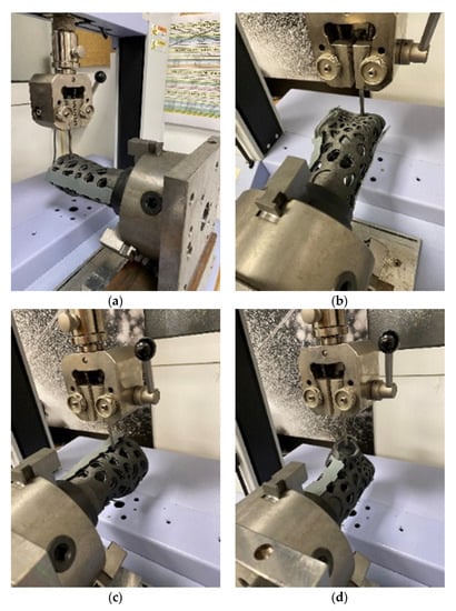
Figure 18.
Load test set-up: (a) flexion; (b) extension; (c) radial deviation; and (d) ulnar deviation.
Table 3.
Applied load during the mechanical testing of each tested movement type.
3. Results and Discussion
3.1. Computational Design and FEA Optimization Workflow for a Personalized WHO
A programmable modeling tool was developed for a semi-automatic design workflow on customizable 3D-printable WHO models. The interactive CAD interface allows clinicians to adjust the input content for the design of the WHO at each stage. The design parameters taken into consideration are based on DfAM and DfR principles and can be summarized in the following:
- The customizable Voronoi pattern has proved beneficial towards common fabrication issues on overhang angles and has enabled support reduction and simultaneous vertical 3D printing of dual-material design systems.
- Furthermore, the parametric control of the hollowed Voronoi tessellation pattern’s local density and its filleting features allow for targeted local reinforcement and flow of internal stresses, as well as performance-driven material efficiency.
- Dual-material properties for both immobilization and tactile sensation and comfort have been taken into consideration in the early design phases. The physical interaction of the two material cases can be finely tuned through computational design tools. The outer parts’ inner surface is parametrically offset to precisely control the distance between the two material cases. The parametric control of the material interaction allows for multiple iterations and optimization processes that aim for both robust dual-material attachment and easy detachment for sorting and recycling. This design strategy aims to reduce the product’s environmental impact throughout its life cycle.
- Additive thinking has been employed through the provision of advanced functionalities by means of embedded NFC and RFID tags for data transmission (i.e., IoT).
- Finally, the flexible bands with the fastening mechanisms can easily be unrolled within the interactive CAD interface in order to be printed flat. This unrolling feature allows for a simplification of the fabrication process (Figure 19).
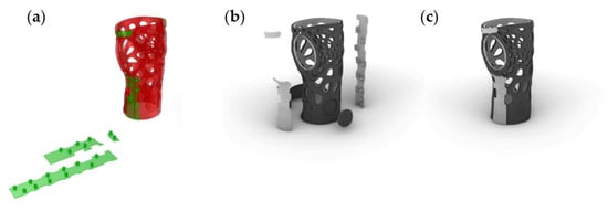 Figure 19. Design of WHO: (a) unrolling of bands; (b) WHO in explosion; (c) WHO assembled.
The preliminary FEA results indicated an additional region in need of immobilization, suggesting the formation of three bands in total. Figure 20 demonstrates the min and max von Mises stresses developed, whereas Figure 21 demonstrates the displacements under the four different load cases. Table 4 summarizes the FEA numerical results.
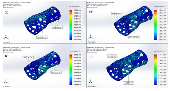
Figure 20.
Predicted von Mises stresses under: (a) Flexion; (b) Radial deviation; (c) Extension; (d) Ulnar deviation.
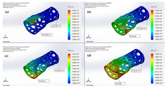
Figure 21.
Predicted displacements under (a) flexion; (b) radial deviation; (c) extension; and (d) ulnar deviation.
Table 4.
FEA numerical results.
As illustrated in Figure 22, the relative displacement of the parts exhibits similar behavior, with low values representing narrow variations, except for the flexion movement, where greater displacement is presented due to the orientation of the applied load application’s orientation against the parts’ contact axes. The von Mises stress results reflect the maximum and minimum stress levels experienced by the wrist splint during each type of movement. With respect to the outcome of our displacement investigation, the von Mises stresses results support the idea that the flexion movement causes increased stress distribution for the maximum values. The maximum von Mises stress experienced during flexion indicates that the design of the WHO is not well-suited to resist the high stresses that occur during this movement; therefore, design optimization was implemented. Considering both our von Mises stress and displacement analysis, we incorporated an extra fastening point in the splint design.
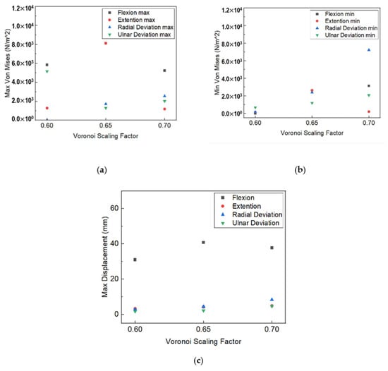
Figure 22.
Voronoi scaling factor influence on (a) max von Misses stress value; (b) min von Misses stress value; (c) max displacement.
3.2. Slicing and Fabrication of WHO
The printing parameters selected for the materials utilized for the manufacturing of the WHO according to the implemented printability tests are presented in Table 5. The 1st and 2nd columns show the printing parameters of TX1501-7.3% CFs and the TPU for the two main components, respectively, while the 3rd column displays the printing parameters set for the manufacturing of the TPU fasteners. The lids were also manufactured with TX1501-7.3%CFs utilizing the printing parameters exhibited in the 1st column.
Table 5.
Printing parameters for TX1501-7.3%CFs parts, TPU main components & TPU fasteners.
The physical model of the developed WHO fabricated with FFF technology is presented in Figure 23.
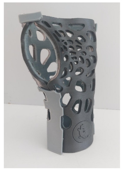
Figure 23.
The fabricated developed WHO.
3.3. In Vitro Assessment of the Materials Used in WHO Development: Skin Sensitization
In terms of their skin-sensitizing potential, it should be noted that the materials used in the WHO development came in direct contact with the skin cells (Hs27). As already mentioned, the TPU (TPUa) and TX1501 7.3% CFs (TX1501b) were used for WHO development. A commercial TPU with antimicrobial properties (TPUb) and pure TX1501 (TX1501a) were also tested in pairs, respectively. After 24 and 48 h of exposure, the release of the proinflammatory cytokines IL-18 and TNF-α in the cell culture medium was measured by ELISA. After performing the calibration curves for IL-18 and TNF-α and the subsequent analysis of concentrations (pg/mL) obtained by means of the equation of the straight line generated by the calibration curve, the average of each sample was calibrated and compared with its respective control independently according to the exposure times. The results were analyzed by performing one-way ANOVA tests, where p-values > 0.05 were not considered statistically significant. At least 3 separate experiments were performed. As shown in the graphs (Figure 24), no significant detection of the proinflammatory cytokines upon exposure of the cells to the materials used in the WHO development was observed compared to the control samples. These findings led to the conclusion that WHO materials might not induce inflammation as an indicator of skin sensitization.
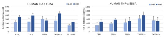
Figure 24.
In vitro skin sensitizing potential of WHO materials: TPUa (commercial pure TPU), TPUb (commercial TPU with antimicrobial properties), TX1501a (pure TX1501), and TX1501b (developed TX1501 with 7.3%CFs).
3.4. Physical Validation: Dimensional Accuracy
With regard to the front part of the 3D-printed WHO, which comes into contact with the palm of the hand, the tolerance distribution chart presented in Figure 25b demonstrates that 24.84% of the component surfaces exhibit tolerance values within the range (−0.1 mm, 0.1 mm). Positive maximum deviations were observed locally near the wrist, measuring 1.599 mm, whereas negative deviations reached 0.822 mm along the fitting line (Figure 25a). The majority of the part tolerance values were measured between −0.8 mm and −0.1 mm, implying the existence of undersized regions, possibly related to material shrinkage during solidification. Furthermore, from Figure 25b, we can deduce that the center of the distribution approximates the value −0.2 mm.
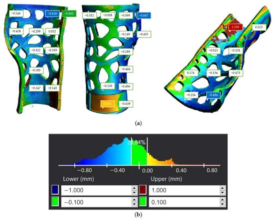
Figure 25.
Tolerance distribution in mm for first component of the 3D-printed WHO: (a) component illustration; (b) generated chart.
With respect to the second part of the brace, the tolerance distribution chart seen in Figure 26b shows that 46.15% of the component surfaces indicate tolerance values in the range (−0.1 mm, 0.1 mm), while the rest of the tolerance values are distributed both over positive and negative values. The maximum positive deviation appeared to reach 0.478 mm, while under-sizing was considerably limited compared to the first component by exhibiting a maximum negative deviation of 0.333 mm, as depicted in Figure 26a. Furthermore, from Figure 26b, we can infer that the center of the distribution is close to the value −0.05 mm.
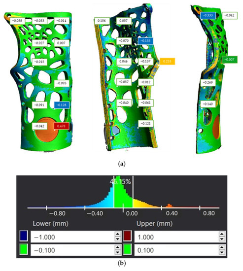
Figure 26.
Tolerance distribution in mm for second component of the 3D-printed WHO: (a) component illustration; (b) generated chart.
3.5. WHO Mechanical Testing Results
Figure 27 presents the generated force–displacement diagram during the implementation of the mechanical testing, while the splint-relative displacements exhibited at the maximum applied load of each case are presented in Table 6. It can be derived from Figure 27 that in the case of ulnar and radial deviation, the displacement that occurs is less compared to flexion and extension for a load value greater than approximately 15 N. Moreover, Table 6 indicates that the maximum relative displacement was presented during the realization of the flexion movement when the maximum tested load was also applied. However, the developed WHO did not exhibit breakage in none of the tested cases, and therefore, since the loads applied exceed the force value that could be exerted by an injured hand, it can be concluded that the presented WHO can withstand the mechanical loads applied in a real case.
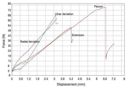
Figure 27.
Experimental results of the tested WHO load cases.
Table 6.
Results of the mechanical testing on the WHO.
4. Conclusions
The present study aimed to develop an integrative methodology for a precompiled customization system by means of material selection and an interactive CAD interface for 3D-printed WHOs. A multifaceted and interdisciplinary workflow for the development of a wrist orthopedic device has been presented, incorporating reverse engineering tools, integrative computational design, dual-material manufacturing, and functionality validation procedures. For the production of a lightweight as well as functional WHO, the proposed design was generated after material efficiency optimization and according to DfAM and DfR principles. The 3D-printing procedure of the WHO components was designated according to the preceding printability evaluation and process parameter optimization in order to accomplish efficient printing of the designed geometry and adequate surface quality and minimize the risk of defective parts generation.
Furthermore, the final manufactured WHO was evaluated in terms of mechanical properties, dimensional accuracy, and toxicological behavior. The bending mechanical testing implemented to examine the WHO’s mechanical behavior in four basic wrist movements confirms the efficient support of the designed WHO since, despite the loading with conservative high force values, failure occurred in none of the tested cases.
Regarding the validation of the presented WHO’s dimensional accuracy, the data extracted from the 3D scanning imply that approximately 50% and 25% of the two main components' tolerance values are within the range (−0.1mm, 0.1mm), while one component presents mainly under-dimensioned regions. Furthermore, the in vitro testing of the WHO’s materials, which aimed to investigate their sensitizing potential by performing an ELISA, showed no significant detection of proinflammatory cytokines as a factor of skin sensitization.
The developed methodology has revealed certain limitations during both the design and manufacturing procedures. Current steps in the design workflow only allow for single-thickness properties throughout the limb’s freeform surface and, therefore, limited customization in terms of tightness properties. Future design steps may also allow for zones of customizable thickness (i.e., variable-thickness normal vector magnitude) for zones of variable compression. In regard to the printing procedure, challenges posed due to dual-material extrusion in terms of mitigating dripping, preventing the clogging of the temporarily idle nozzle, and the optimal determination of the material offset to accomplish material contact without intersection were managed. Furthermore, the future employment of alternative AM systems (e.g., resin-based Vat photopolymerization systems) is expected to pose new challenges in terms of biocompatibility [29], suggesting the currently limited representativeness of material properties only related to thermoplastics. Moreover, to minimize the total time for the development of the WHO, the optimization of the printing parameters was considered to counterbalance surface quality and production time.
The employed multi-material approach allows for integrated padding, as well as a soft hinge to ease donning and doffing. Future actions aligned with the present work will include user experience evaluation studies by incorporating both quantitative data on the donning and doffing time required, as well as qualitative comments from the user. Zones of variable compression for tightness adjustments, tactile sensation, thermal comfort mapping, and irritation points on the developed perforated prototype shall be considered for further design optimization. Furthermore, additional improvements in patient preference and customization in color options are intended. Finally, future investigations could focus on the optimization of the precompiled customization system by means of a user-friendly cloud-based interactive CAD interface for 3D-printed WHOs.
Author Contributions
Conceptualization, V.T., A.P., D.N., and A.K.; methodology, V.T., A.P., D.N., P.Z., and A.K.; software, V.T., A.P., and P.Z.; validation, A.P., D.N., and P.Z.; investigation, A.P., and V.T.; writing—original draft preparation, V.T., A.P., D.N., P.Z.., and A.K.; writing—review and editing, V.T., A.P., D.N., P.Z., and A.K.; visualization, V.T., A.P., D.N., and P.Z.; supervision, A.K.; project administration, A.K.; funding acquisition, A.K. All authors have read and agreed to the published version of the manuscript.
Funding
This research was funded by the European research project Repair3D—Recycling and Repurposing of Plastic Waste for Advanced 3D-Printing Applications (Grant Agreement no. 814588).
Data Availability Statement
Data are available upon request.
Acknowledgments
We would like to thank Calzaturificio Dal Bello Srl for testing the mechanical properties of the demonstrator and providing the results, Centre Scientifique and Technique De L’industrie Textile Belge for material compounding and filament development, Universiteit Gent for material provision, and Fundacio Eurecat for provision of the materials’ mechanical testing results. We would also like to thank our colleague Efstratios Kroustis for his vital technical support in the 3D printing process.
Conflicts of Interest
There are no conflict of interest.
References
- Kumar, A.; Chhabra, D. Adopting Additive Manufacturing as a Cleaner Fabrication Framework for Topologically Optimized Orthotic Devices: Implications over Sustainable Rehabilitation. Clean. Eng. Technol. 2022, 10, 100559. [Google Scholar] [CrossRef]
- Soares, B.; Ribeiro, I.; Cardeal, G.; Leite, M.; Carvalho, H.; Peças, P. Social Life Cycle Performance of Additive Manufacturing in the Healthcare Industry: The Orthosis and Prosthesis Cases. Int. J. Comput. Integr. Manuf. 2021, 34, 327–340. [Google Scholar] [CrossRef]
- Barrios-Muriel, J.; Romero-Sánchez, F.; Alonso-Sánchez, F.J.; Salgado, D.R. Advances in Orthotic and Prosthetic Manufacturing: A Technology Review. Materials 2020, 13, 295. [Google Scholar] [CrossRef] [PubMed]
- Webster, J.B.; Murphy, D.P. Atlas of Orthoses and Assistive Devices; Elsevier: Amsterdam, The Netherlands, 2019. [Google Scholar] [CrossRef]
- Li, J.; Tanaka, H. Rapid Customization System for 3D-Printed Splint Using Programmable Modeling Technique—A Practical Approach. 3D Print. Med. 2018, 4, 5. [Google Scholar] [CrossRef] [PubMed]
- Zhang, X.; Fang, G.; Dai, C.; Verlinden, J.; Wu, J.; Whiting, E.; Wang, C.C.L. Thermal-Comfort Design of Personalized Casts. In Proceedings of the UIST’17: 30th Annual ACM Symposium on User Interface Software and Technology, Québec City, QC, Canada, 22–25 October 2017. [Google Scholar] [CrossRef]
- Lin, H.; Shi, L.; Wang, D. A Rapid and Intelligent Designing Technique for Patient-Specific and 3D-Printed Orthopedic Cast. 3D Print. Med. 2015, 2, 4. [Google Scholar] [CrossRef] [PubMed]
- Fitch, M.T.; Nicks, B.A.; Pariyadath, M.; McGinnis, H.D.; Manthey, D.E. Basic Splinting Techniques. N. Engl. J. Med. 2008, 359, e32. [Google Scholar] [CrossRef] [PubMed]
- Kelly, S.; Paterson, A.; Bibb, R. A Review of Wrist Splint Designs for Additive Manufacture. In Proceedings of the 14th Rapid Design, Prototyping and Manufacture conference (RDPM 14), Loughborough, UK, 15–16 December 2015. [Google Scholar]
- Sala, F.; Carminati, M.; D’Urso, G.; Giardini, C. A Feasibility Analysis of a 3D Customized Upper Limb Orthosis. Procedia CIRP 2022, 110, 208–213. [Google Scholar] [CrossRef]
- Chen, Y.-J.; Lin, H.; Zhang, X.; Huang, W.; Shi, L.; Wang, D. Application of 3D-Printed and Patient-Specific Cast for the Treatment of Distal Radius Fractures: Initial Experience. 3D Print. Med. 2017, 3, 11. [Google Scholar] [CrossRef] [PubMed]
- Lunsford, C.; Grindle, G.; Salatin, B.; Dicianno, B.E. Innovations With 3-Dimensional Printing in Physical Medicine and Rehabilitation: A Review of the Literature. PM&R 2016, 8, 1201–1212. [Google Scholar] [CrossRef]
- Kim, H.; Jeong, S. Case Study: Hybrid Model for the Customized Wrist Orthosis Using 3D Printing. J. Mech. Sci. Technol. 2015, 29, 5151–5156. [Google Scholar] [CrossRef]
- Munhoz, R.; Moraes, C.A. da C.; Tanaka, H.; Kunkel, M.E. A Digital Approach for Design and Fabrication by Rapid Prototyping of Orthosis for Developmental Dysplasia of the Hip. Res. Biomed. Eng. 2016, 32, 63–73. [Google Scholar] [CrossRef]
- Mavroidis, C.; Ranky, R.G.; Sivak, M.L.; Patritti, B.L.; DiPisa, J.; Caddle, A.; Gilhooly, K.; Govoni, L.; Sivak, S.; Lancia, M.; et al. Patient Specific Ankle-Foot Orthoses Using Rapid Prototyping. J. Neuroeng. Rehabil. 2011, 8, 1. [Google Scholar] [CrossRef] [PubMed]
- Milusheva, S.M.; Tosheva, E.Y.; Hieu, L.C.; Kouzmanov, L.V.; Zlatov, N.; Toshev, Y.E. Personalised Ankle-Foot Orthoses Design Based on Reverse Engineering. In Proceedings of the Intelligent Production Machines and Systems—2nd I*PROMS Virtual International Conference, Virtual, 3–14 July 2006; pp. 253–257. [Google Scholar] [CrossRef]
- Worrell, E.; Reuter, M.A. Handbook of Recycling: State-of-the-Art for Practitioners, Analysts, and Scientists. In Handbook of Recycling: State-of-the-Art for Practitioners, Analysts, and Scientists; Elsevier: Amsterdam, The Netherlands, 2014; pp. 1–581. [Google Scholar] [CrossRef]
- Joseph, B.; James, J.; Kalarikkal, N.; Thomas, S. Recycling of Medical Plastics. Adv. Ind. Eng. Polym. Res. 2021, 4, 199–208. [Google Scholar] [CrossRef]
- Gavalas, I.; Ntenekou, D.; Karatza, A.; Damilos, S.; Saliakas, S.; Koumoulos, E.P. Leaching of Nano-Additives as a Method for Life-Cycle Suitability: A Study on 3D-Printed Nanocomposites for Wearables Applications. Processes 2023, 11, 2053. [Google Scholar] [CrossRef]
- ISO 10993-10:2021; Biological Evaluation of Medical Devices—Part 10: Tests for Skin Sensitization. ISO: Genève, Switzerland, 2021.
- OECD. Test No. 442D: In Vitro Skin Sensitisation; OECD Publishing: Paris, France, 2022. [Google Scholar] [CrossRef]
- Tang, Y.; Zhao, Y.F. A Survey of the Design Methods for Additive Manufacturing to Improve Functional Performance. Rapid Prototyp. J. 2016, 22, 569–590. [Google Scholar] [CrossRef]
- HandySCAN 300TM HandySCAN 700TM. Available online: https://www.spectratech.gr/Web/Creaform/pdf/HandySCAN-700.pdf (accessed on 11 July 2023).
- Aurenhammer, F.; Klein, R.; Lee, D.T. Voronoi Diagrams and Delaunay Triangulations; World Scientific: Singapore, 2013; pp. 1–337. [Google Scholar] [CrossRef]
- Pillemer, R. Anatomy and Function of the Wrist. In Handbook of Upper Extremity Examination; Springer: Berlin/Heidelberg, Germany, 2022; pp. 95–100. [Google Scholar] [CrossRef]
- Cazon, A.; Kelly, S.; Paterson, A.M.; Bibb, R.J.; Campbell, R.I. Analysis and Comparison of Wrist Splint Designs Using the Finite Element Method: Multi-Material Three-Dimensional Printing Compared to Typical Existing Practice with Thermoplastics. Proc. Inst. Mech. Eng. H 2017, 231, 881–897. [Google Scholar] [CrossRef] [PubMed]
- Vanswearingen, J.M. Measuring Wrist Muscle Strength. J. Orthop. Sports Phys. Ther. 1983, 4, 217–228. [Google Scholar] [CrossRef] [PubMed]
- Delp, S.L.; Grierson, A.E.; Buchanan, T.S. Maximum Isometric Moments Generated by the Wrist Muscles in Flexion-Extension and Radial-Ulnar Deviation. J. Biomech. 1996, 29, 1371–1375. [Google Scholar] [CrossRef] [PubMed]
- Wulff, J.; Schweikl, H.; Rosentritt, M. Cytotoxicity of Printed Resin-Based Splint Materials. J. Dent. 2022, 120, 104097. [Google Scholar] [CrossRef] [PubMed]
Disclaimer/Publisher’s Note: The statements, opinions and data contained in all publications are solely those of the individual author(s) and contributor(s) and not of MDPI and/or the editor(s). MDPI and/or the editor(s) disclaim responsibility for any injury to people or property resulting from any ideas, methods, instructions or products referred to in the content. |
© 2023 by the authors. Licensee MDPI, Basel, Switzerland. This article is an open access article distributed under the terms and conditions of the Creative Commons Attribution (CC BY) license (https://creativecommons.org/licenses/by/4.0/).