Abstract
This paper presents the design and experimental validation of a novel human–machine redundant braking system (HMRBS) for aftermarket low-speed electric vehicles (LSEVs) to realise the backup redundancy ability and improve active safety. First, the HMRBS is designed by connecting the electro-hydraulic braking (EHB) unit oil pipelines in parallel with the manual braking (MB) unit through two three-way shuttle valves. Then, the mathematical model of the EHB subsystem is built, and a master cylinder pressure controller with adaptive fuzzy proportion integration differentiation (PID) and a servo motor speed controller with double-closed-loop proportion integration (PI) are proposed to improve the system response performance. Following this, the co-simulation model of the proposed closed-loop system is established based on AMESim and MATLAB/Simulink to validate the feasibility of the proposed control strategy. Finally, the effectiveness of the HMRBS is also validated by test rig and vehicle experiments. The results imply that the modified LSEV with the HMRBS meets the requirements of vehicle active braking ability and manual braking redundancy. Furthermore, the proposed controller can significantly enhance pressure control accuracy compared to the classical PID controller. The deceleration fluctuation and braking distance in the active braking mode are smaller than those in the manual braking mode, indicating that the proposed system makes the braking effect more stable and safer.
1. Introduction
Electrification and intelligence are currently emerging as global trends in the vehicle industry. Brake-by-wire technology has been greatly developed and applied to vehicle active braking systems [1,2,3]. With the help of the active braking system, intelligent vehicles equipped with advanced driver assistance systems (ADAS), e.g., adaptive cruise control (ACC) and autonomous emergency braking (AEB), can significantly improve driving safety [4,5,6].
Currently, more and more passenger and commercial vehicles are equipped with brake-by-wire systems. However, most LSEVs, such as electric sightseeing vehicles, street sweepers, or light electric logistics vehicles that run on fixed routes or in closed scenes, have not been equipped with brake-by-wire systems due to the low quantity, high development costs, and various customised requirements [7]. In addition, the different mechanical structures and vehicle dynamic performance requirements increase the development difficulty. The brake-by-wire systems should be designed, matched, calibrated, and debugged according to different types of vehicles. Therefore, it is necessary to develop an automatic braking system with a simple structure, high reliability, low cost, easy modification, and low debugging difficulty to improve the active braking capability of LSEVs.
Electro-hydraulic braking (EHB) systems are currently the mainstream active braking mode used in intelligent vehicles [8,9]. Some EHB products have been successfully developed, such as the MKC1 and iBooster [10,11]. Meanwhile, many scholars are also constantly improving and optimising the structure of the EHB system, e.g., a master cylinder based on the speed servo system with an anti-lock function [12], and a dual redundant brake-by-wire for highly automated driving safety [13]. A redundancy braking system with EHB has the ability to activate the vehicle’s emergency and consistency brake, even if the brakes are not activated due to electrical or mechanical failures or external shocks [14]. However, the application object of all the above EHB systems is mass-produced new passenger or commercial vehicles, which makes them unsuitable for use in the aftermarket LSEVs to achieve active braking function.
EHB control strategies play a critical role in braking performance and safety. Recent literature shows increasing interest in EHB control strategies. A double-closed-loop PI feedback control system was proposed to obtain a better position–pressure relationship, where the inner loop and outer loop control the position and pressure, respectively [15]. However, the characteristics of the brake oil, the friction, and the large transmission ratio of the transmission mechanism will cause strong nonlinearity, thereby affecting the robustness of the controller [13,16]. A fuzzy PI controller for the hydraulic pressure control of the master cylinder was designed to improve the robustness of the PI control method [17,18,19]. A sliding mode control method of the electro-hydraulic brake master cylinder pressure was proposed, aiming at the nonlinear problems such as oscillation and low-speed creeping of the master cylinder in the control process [20]. However, the position of the master cylinder piston is not considered in the fuzzy PI or sliding mode controller, resulting in low control accuracy. Therefore, it is necessary to design a controller with fast response, high reliability, and low cost to ensure the master cylinder pressure accuracy and stability of the EHB system.
Aiming at these problems, a novel human–machine redundant braking system (HMRBS) is proposed in this paper, and its innovation points are as follows:
- On the premise of retaining the original braking system of LSEV, a low-cost HMRBS is designed by connecting the oil pipelines of the EHB unit in parallel with the manual braking (MB) unit through two three-way shuttle valves. As a result, the HMRBS has two braking modes, active and manual braking modes, thus ensuring the redundancy of braking backup.
- The HMRBS mathematical model is established, and the master cylinder pressure controller with adaptive fuzzy PID and the servo motor speed controller with double-closed-loop PI are designed. Moreover, a test rig is developed, and an LSEV is modified with the HMRBS. Finally, the effectiveness of the proposed braking system is validated by experiments.
The rest of this paper is organised as follows. Section 2 illustrates the structure design scheme, operating principles, and mathematical model. Section 3 introduces the controller design of the HMRBS. In Section 4, the co-simulation results are given to verify the effectiveness of the proposed scheme. The experiments are carried out on a test rig and modified test LSEV, respectively, in Section 5. Finally, several conclusions are given in Section 6.
2. Design Scheme and Mathematical Model
2.1. Design Scheme
Figure 1 shows the schematic of the human–machine redundant braking system (HMRBS) proposed in this paper. The system mainly comprises the MB unit, the EHB unit, and the wheel cylinder braking (WCB) unit. The EHB unit is connected in parallel to the original vehicle braking system (i.e., MB unit) through two three-way shuttle valves. The MB unit is consistent with the original vehicle system without any changes. It has the advantage of having a simple structure, high reliability, low cost, easy modification, and low debugging, especially for vehicles in the aftermarket. Therefore, the HMRBS has two braking modes: active braking mode and manual braking mode. The HMRBS works as follows:
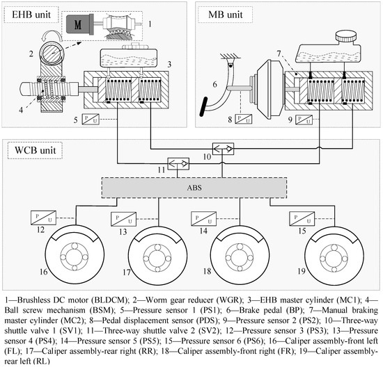
Figure 1.
The design schematic of the HMRBS.
- Active braking mode: First, the EHB subsystem receives the braking pressure request signal via the controller area network (CAN) from upper intelligent driving systems. Then, the torque output by the brushless DC motor (BLDCM) is increased via the worm gear reducer (WGR). Meanwhile, the rotary motion of the worm gear is converted into the translational motion of the pushrod of the master cylinder 1 (MC1) through the ball screw mechanism (BSM). The high-pressure oil from MC1 enters the two three-way shuttle valves, i.e., SV1 and SV2, and the valve cores of SV1 and SV2 will move to the right. The independent oil circuit system comprises EHB and WCB units in this mode. Finally, the oil enters the brake caliper and increases the braking pressure.
- Manual braking mode: In this mode, the oil pressure of the master cylinder 2 (MC2) increases under the action of the foot pedal force, lever mechanism, and vacuum booster (some LSEVs do not have any vacuum booster). Then, the valve cores move to the left so that the MB and WCB units form an independent oil circuit system. The manual braking mode normally works even if the active braking fails. Therefore, the HMRBS can improve vehicle braking safety.
2.2. Mathematical Model
A mathematical model of the system is required for the subsequent co-simulation and controller design to validate the feasibility of the design scheme. Therefore, the mathematical models of BLDCM, transmission mechanism, brake master cylinder, wheel cylinder, and brake line are developed in this paper.
The electromagnetic torque of BLDCM can be expressed as [21]
where Pe stands for electromagnetic power of the motor, Te is electromagnetic torque, and ω is motor angular speed. ia, ib, and ic are the phase currents of three-phase stator windings, respectively. ea, eb, and ec are the back-EMF of three-phase stator windings.
The motor kinematic equation can be obtained by
where Te is electromagnetic torque, TL is the additional load torque, and Bv is the damping coefficient.
The dynamics model of the master cylinder can be written as
where Mm1 and Mm2 stand for the mass of the front piston and the rear piston, respectively. x1 and x2 stand for the displacement of the front piston and the rear piston, respectively. cm1 and cm2 are the respective spring damping coefficients. km1 and km2 are the respective spring stiffness. pm1 and pm2 stand for the pressure of the front and rear chambers, respectively. A is the cross-sectional area of the piston.
The continuity equation of hydraulic transmission of the master cylinder can be written as [22]
where β is the equivalent volume elastic modulus of the brake oil. Vm1 and Vm2 are the volumes of chambers after the front and rear pistons are compensated, respectively. d1 and d2 are the compensation displacement of the front and rear chambers, respectively. Qm1 and Qm2 are the flow of the front and rear chamber brake lines, respectively.
The model of the wheel cylinder can be expressed as [23]
The continuity equation of the hydraulic pressure change of the wheel cylinder can be expressed as
where Mw is the mass of the caliper and xw is the equivalent displacement of the rigid body. Aw is the cross-sectional area of the wheel cylinder piston, ps is the oil pressure on the piston, kw is the equivalent stiffness of the spring in the initial state of the piston, cw is the damping coefficient of the wheel cylinder, xq0 is the equivalent preload of spring, xq1 is the equivalent displacement of the rigid body, Qv is the brake oil flow, and Lw is the initial liquid width of the wheel cylinder.
The continuity equation of the brake line can be written as
where Qp is the flow in the brake line, Pp is the actual pressure in the brake line, Vp is the volume of the brake hose, and β is the equivalent volumetric elastic modulus of brake oil.
The parameters involved in the EHB unit are shown in Table 1.

Table 1.
Parameter in the EHB unit.
3. Controller Design
The HMRBS can realise the independent parallel control of the EHB and MB units. When the vehicle encounters an emergent event, the driver can brake the vehicle by MB unit. If the driver does not notice the emergency, the vehicle can be braked automatically by the EHB unit based on the control strategy. Therefore, the controller of the EHB unit of the HMRBS should be designed to meet braking safety. In the controller design, the master cylinder pressure-tracking performance and control accuracy should be guaranteed [24].
A closed-loop control strategy of the EHB unit is proposed in this paper, including the master cylinder pressure controller with adaptive fuzzy PID and the servo motor speed controller with double-closed-loop PI, shown in Figure 2. kp, ki, and kd are PID control parameters. Δkp, Δki, and Δkd are the variations of the PID control parameters. Ptar is target pressure, Pact actual pressure, utar target voltage, uact actual voltage, itar target current, and iact actual current.
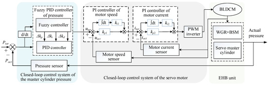
Figure 2.
Closed-loop control strategy of EHB unit pressure.
3.1. Master Cylinder Pressure Controller Design
In the master cylinder (MC1) pressure controller with adaptive fuzzy PID, the error between the expected pressure and the actual pressure and its change rate are the input signals, and the output is the expected speed of the servo motor.
The initial fuzzy PID parameters are set to kp = 11, ki = 1.5, and kd = 1.1. The deviation between the actual master cylinder pressure value obtained by the pressure sensor and the target pressure value sent by the upper controller can be expressed as e = Pact − Ptar, and its rate of change can be expressed as ec = de/dt.
The variables are scaled into the integer discourse domain range of [−6, 6], and both concrete subsets of numbers are {−6, −4, −2, 0, 2, 4, 6}. The fuzzy set corresponding to the basic domain is set to {NB NM NS ZO PS PM PB}. The discourse domain of input variables is divided into seven membership functions: NB (Negative Big), NM (Negative Middle), NS (Negative Small), ZO (Zero), PS (Positive Small), PM (Positive Middle), and PB (Positive Big). Fuzzification of the theoretical domains of e and ec yields a mainly triangular affiliation function, as shown in Figure 3.
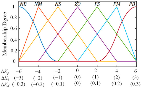
Figure 3.
Membership function of inputs.
The output of the adaptive fuzzy PID controller consists of three correction terms, ∆kp, ∆ki, and ∆kd, which modify the PID control parameters kp, ki, and kd, respectively. The domains and fuzzy subsets for these output terms are defined as follows: the domain of ∆kp is {−6, −4, −2, 0, 2, 4, 6}, the domain of ∆ki is {−3, −2, −1, 0, 1, 2, 3}, and the domain of ∆kd is {−0.6, −0.4, −0.2, 0, 0.2, 0.4, 0.6}. Correspondingly, the fuzzy sets are {NB, NM, NS, ZO, PS, PM, PB}, with a quantification factor of 1 for each term. The membership function type of the input and output variable is mainly triangular, and the membership function is obtained after fuzzification, as shown in Figure 4.
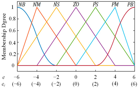
Figure 4.
Membership function of outputs.
Adaptive fuzzy PID control applies the modern control theory to set the parameters of the online controlled object, making the control system adapt to the requirements constantly to achieve better control effects. The formulation of fuzzy control rules requires the integration of the PID parameter-tuning experience. The three parameters, ∆kp, ∆ki, and ∆kd, can be set reasonably and dynamically [25]. Referencing the values of input variables e and ec, adjustments are made to the magnitudes of ∆kp, ∆ki, and ∆kd. During the initial adjustment phase, the error and the error rate between the actual and desired pressure values are relatively high, so a larger ∆kp is chosen to obtain a higher system response rate. A smaller ∆kd is selected to prevent differential saturation, and the integral effect is somewhat weakened. In the middle stage of adjustment, when the values of pressure difference e and its rate of change ec are moderate, the initial value of ∆kp can be appropriately reduced to control the system with minimal overshoot while ensuring a reasonable response rate. To maintain stability, ∆ki, and ∆kd are kept relatively moderate and unchanged. In the later stage, to improve the pressure-tracking stability, ∆kp is increased appropriately, and the integral action is intensified to reduce steady-state error and enhance control accuracy. Considering the sensitivity of the system pressure controller to changes in the kd parameter, ∆kd should be reduced to compensate for the prolonged adjustment process caused by the larger ∆kp value during the initial adjustment phase. Based on the aforementioned parameter adjustment experience, the fuzzy rules are summarised in Table 2.
Table 2.
Fuzzy control rule table.
∆kp, ∆ki, and ∆kd obtained by fuzzy reasoning are a fuzzy set which cannot calibrate the parameters. Therefore, the fuzzy set should be converted into an actual value that can be recognised by the control system [26]. The centroid method is chosen for defuzzification, and can be expressed as
where ui is an element of the domain {u1, u2……ui}, and M(ui) is the value of the membership function when u = ui.
3.2. Servo Motor Speed Controller Design
The rapid response and accurate control of the target signal should be accomplished in the servo motor speed controller with double-closed-loop PI. The motor speed loop is set to the outer loop, and the current loop of the motor is set to the interior loop, respectively.
In the outer loop, the input variable is the difference between the expected and actual speed, and the prospective current of the motor is chosen as the output. The difference between the prospective current and the actual motor current obtained by the current sensor is taken as the input variable of the current interior loop PI controller. Subsequently, the output signal is used as the input of the duty ratio of the PWM inverter. Control of PWM can be achieved by adjusting the duty ratio. Finally, the servo motor is driven to forward or reverse motion, and then the master cylinder piston is pushed or pulled by the transmission mechanism to achieve pressure control.
The principle behind pulse width modulation (PWM) is to compare the waveform (modulating wave) synthesised by the required sawtooth/triangular wave (carrier wave) with a reference voltage and determine the polarity of the PWM output. When the sawtooth wave is fed into the inverting input of the comparator and exceeds the reference voltage, the output polarity is the opposite of the sawtooth wave. When the sawtooth wave is fed into the non-inverting input of the comparator and exceeds the reference voltage, the output polarity is the same as the sawtooth wave.
4. Simulation and Discussion
4.1. Co-Simulation Model
A co-simulation model of the HMRBS is built with MATLAB/Simulink and AMESim to validate the feasibility of the control algorithm of master cylinder pressure tracking. The EHB unit consists of the controller sub-model and the hydraulic mechanism sub-model. The controller sub-model is developed in MATLAB/Simulink software based on the closed-loop control strategy. The hydraulic mechanism sub-model includes the transmission mechanism, brake master cylinder, brake wheel cylinder, and brake pipeline, accomplished in AMEsim software. The exchange of data of the master cylinder pressure and target motor torque is realised in the co-simulation, shown in Figure 5.
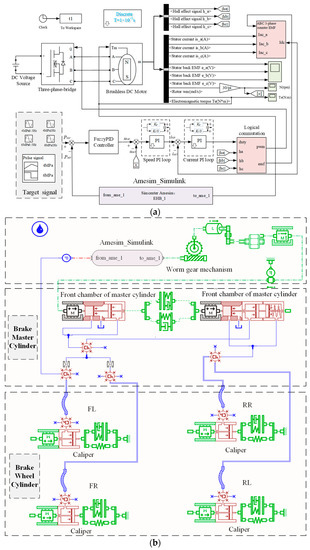
Figure 5.
The co-simulation model of the EHB unit of HMRBS: (a) the controller sub-model in Matlab/Simulink; and (b) hydraulic mechanism sub-model in AMESim.
4.2. Simulation Results
The classical PID and fuzzy PID strategies are compared and analysed in co-simulation. Two signal-inputting simulation conditions are used as follows: (1) a step signal with 6 MPa at 0.5 s; (2) a sine signal with an offset of 3 MPa, an amplitude of 3 MPa, and a frequency of 1 Hz. The results are displayed in Figure 6 and Figure 7.
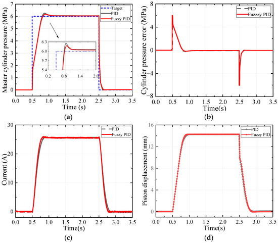
Figure 6.
The step target pressure-tracking simulation results: (a) pressure-tracking curve; (b) pressure error curve; (c) electric current curve; and (d) piston displacement curve.
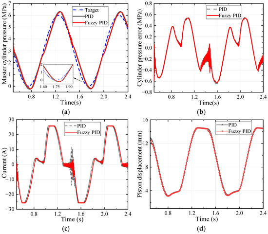
Figure 7.
The sinusoidal signal target pressure-tracking simulation results: (a) pressure-tracking curve; (b) pressure error curve; (c) electric current curve; and (d) piston displacement curve.
Figure 6 shows the results of the case with the step signal. The simulation case can evaluate the transient response of rapid pressurisation, rapid decompression, and pressure-holding capacity of the master hydraulic pressure under emergency active braking conditions. The rise time of PID and fuzzy PID is almost the same. The overshoot of PID is 0.26 MPa, and the steady-state error is 0.05 MPa. The overshoot of the fuzzy PID proposed is 0.18 MPa, and the steady-state error is 0.04 MPa, which are reduced by 42% and 20%, respectively.
Figure 7 shows the results of the case with the sine signal. The simulation case can validate the dynamic response of the HMRSB under the periodically changing target pressure. The maximum tracking error of PID is 0.65 MPa, while the error of fuzzy PID is 0.62 MPa, which is reduced by 4.6%.
Therefore, the fuzzy PID proposed in this paper is superior to PID in overshoot, steady-state errors, and tracking errors. The results prove the effectiveness and accuracy of the fuzzy PID control strategy.
5. Test and Discussion
5.1. Test Rig Results
Compared with the simulation analysis, the actual system has uncertainties such as parameter variations, modeling errors, and external disturbances. Therefore, the robustness of the proposed method can be proved by rig and vehicle experiments. A brake system hardware-in-the-loop (HIL) test rig is built to evaluate the dynamic pressure characteristics of the HMRBS, as shown in Figure 8. The detailed specifications are listed in Table 3. A pressure controller is constructed in MATLAB/Simulink to receive the desired pressure value as input and generate the desired speed for the servo motor. The desired speed of the servo motor is then sent to the motor controller via the CAN Bus analyser. After passing through the motor speed controller and current controller, the motor control torque is outputted to achieve speed control of the motor, thereby driving the master cylinder piston to operate and complete the electro-hydraulic braking. The control code is developed based on the feedback signals from the current sensor and speed sensor in the motor to meet different control performance requirements. The time–pressure target signals of step tests and sine sweep tests are carried out in this paper. In the step tests, the system is sent step signals with amplitude of 4 MPa and 6 MPa; in the sine sweep tests, the sine signals with an offset of 3 MPa and 2 MPa, an amplitude of 3 MPa and 2 MPa, and a frequency of 0.5 Hz and 1Hz are input. The transient response and holding capacity of the master cylinder pressure were acquired.
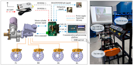
Figure 8.
The HIL test rig.
Table 3.
The specifications of the test rig.
Figure 9 shows the time–pressure history results of the step target pressure-tracking test. The pressure value of the master cylinder can coincide well with the target signal with 4 MPa and 6 MPa, respectively. The actual pressure overshoot of the test is kept within 0.6 MPa, and the steady-state error is kept within 0.3 MPa, which meets the basic requirements of the HMRSB for braking efficiency.
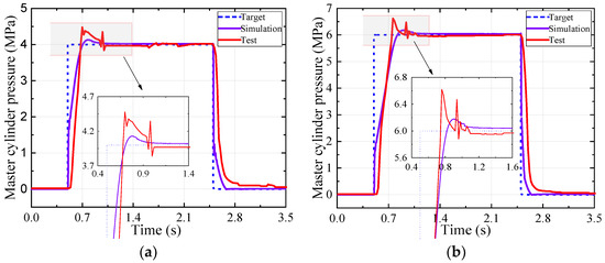
Figure 9.
The test results of the step target pressure: (a) amplitude 4 MPa; and (b) amplitude 6 MPa.
The test results of the sine target pressure tracking are provided in Figure 10. Different signal offsets (2 MPa and 3 MPa), amplitude (2 MPa and 3 MPa), and frequency (0.5 Hz and 1 Hz) were set in the test. The results show that the pressure of the master cylinder has high accuracy in tracking the periodic dynamic target pressure. The maximum tracking error between the actual and target values is within 0.7 MPa, which appears in Figure 10d. However, there are also shortcomings, such as fluctuations of the pressure signal intermittently, which are proportional to the target pressure amplitude and frequency. The fluctuations in all the tests are mainly due to the uncertain frictional characteristics of the actual transmission components, which are not considered in the simulation model.
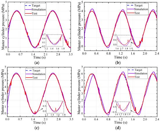
Figure 10.
The sinusoidal target pressure test results: (a) amplitude 2 MPa, frequency 0.5 Hz; (b) amplitude 2 MPa, frequency 1 Hz; (c) amplitude 3 MPa, frequency 0.5 Hz; and (d) amplitude 3 MPa, frequency 1 Hz.
5.2. Test Vehicle Test Results
An LSEV (sightseeing vehicle) was retrofitted with the HMRBS proposed in this paper to verify its braking performance in the road test, shown in Figure 11. A high-precision GPS/IMU system was used to obtain the braking deceleration, vehicle speed, and braking distance. The relevant requirements for road tests mainly refer to GB/T 21268-2014 and GB/T 7258-2017 [27,28].
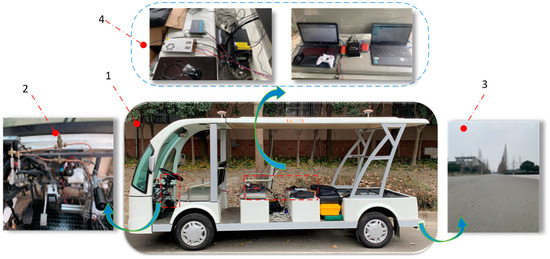
Figure 11.
A test LSEV equipped with HMRBS. 1—Sightseeing vehicle; 2—HMRBS; 3—Test road; 4—High precision GPS/IMU system and CAN data analyser.
Considering that the test vehicle is used in a closed scenario, the maximum braking pressure of the master cylinder is limited to 4 MPa, and it can meet the vehicle braking demand. During the test, the vehicle was accelerated to 30 km/h and then held at a constant speed for a while before the brakes were applied. Emergency and mild brakes with active and manual braking modes were applied to evaluate the braking performance in different conditions.
The dynamic response of active and manual braking modes in the emergency braking condition is presented in Figure 12. The master cylinder pressure and deceleration generated by the EHB unit increased stably. The speed slowed down linearly, indicating that the EHB unit is reliable and effective in the active braking mode. The manual braking mode has the same deceleration trend as the active braking mode. It indicates that the modification does not affect the manual braking performance. Therefore, the MB unit can be used as a backup of the EHB unit, and the design enables dual braking and independent control.
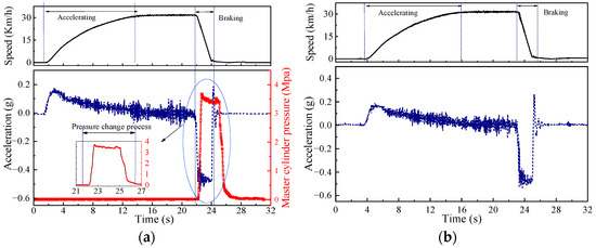
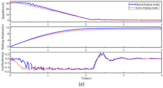
Figure 12.
Emergency braking test: (a) active braking mode; (b) manual braking mode; and (c) comparison of vehicle dynamics characteristics.
Figure 12c illustrates the vehicle speed, acceleration, and braking distance after the HMRBS receives the brake signal. The braking deceleration fluctuates around −0.5 g, and the braking time is about 2.2 s in both braking modes. But the braking distance of the manual and active braking modes is 11.5 m and 10.8 m, respectively. Moreover, the deceleration fluctuation generated by the EHB unit is smaller than that of the MB unit. Therefore, the active braking mode is more stable and effective.
The dynamic response of active and manual braking modes in the mild braking condition is presented in Figure 13. The braking distance of the manual and active braking modes is about 20.4 m and 13.6 m, respectively. The braking deceleration fluctuates around −0.2 g and −0.35 g, and the braking time is 4.7 s and 2.9 s, respectively. The EHB unit produces fewer deceleration fluctuations than the MB unit, and the braking force is more stable.
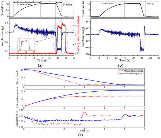
Figure 13.
Mild braking test: (a) active braking mode; (b) manual braking mode; and (c) comparison of vehicle dynamics characteristics.
Therefore, the EHB unit is superior to the MB unit in response speed and braking efficiency in the HMRBS, and the braking effect is more stable. Furthermore, on the premise of retaining the original braking system, the low-cost HMRBS ensures the redundancy of braking backup in case of power failure of the EHB unit. It can meet the braking performance and safety requirements of the LSEV.
6. Conclusions
- An HMRBS with a simple structure, high reliability, low cost, easy modification, and low debugging difficulty for aftermarket LSEVs has been proposed in this paper. The HMRBS retains the original braking system of the LSEV. It can realise the vehicle braking backup redundancy ability and improve active safety.
- A master cylinder pressure controller with adaptive fuzzy PID and a servo motor speed controller with double-closed-loop PI have been designed to improve the system response performance. Simulation and test rig experiments have validated the feasibility and pressure-tracking performance. The dynamic pressure-tracking error is less than 0.6 MPa, and the steady-state error is within 0.3 MPa.
- An LSEV has been retrofitted with an HMRBS to verify its braking performance in the road test. As a result, the maximum braking deceleration of both manual and active braking modes can reach −0.5 g. Significantly, the deceleration fluctuation and braking distance of the EHB unit are smaller than that of the MB unit, and its braking effect is more stable.
Author Contributions
Conceptualisation, C.W. and S.S.; experiment and data analysis, W.Q., L.C. and G.T.; writing, S.S., Y.T. and K.L.; resources, P.D.; revision, X.H. and C.W.; funding acquisition, S.S. All authors have read and agreed to the published version of the manuscript.
Funding
This research was funded by the Science & Technology Department of Sichuan Province (2022YFG0094, 2021YFG0070).
Data Availability Statement
The datasets used and analysed during the current study are available from the corresponding author upon reasonable request.
Conflicts of Interest
The authors declare no conflict of interest.
Abbreviation
| HMRBS | Human–machine redundant braking system |
| LSEVs | Low-speed electric vehicles |
| EHB | Electro-hydraulic braking |
| MB | Manual braking |
| PID | Proportion integration differentiation |
| PI | Proportion integration |
| ADAS | Advanced driver assistance systems |
| ACC | Adaptive cruise control |
| AEB | Autonomous emergency braking |
| WCB | Wheel cylinder braking |
| CAN | Controller area network |
| BLDCM | Brushless DC motor |
| WGR | Worm gear reducer |
| BSM | Ball screw mechanism |
| MC | Master cylinder |
| SV | Shuttle valves |
| PS | Pressure sensor |
| BP | Brake pedal |
| PDS | Pedal displacement sensor |
| FL | Caliper assembly—front left |
| FR | Caliper assembly—front right |
| RR | Caliper assembly—rear left |
| RL | Caliper assembly—rear left |
References
- Chiara, F.; Canova, M. A review of energy consumption, management, and recovery in automotive systems, with considerations of future trends. Proc. Inst. Mech. Eng. Part D J. Automob. Eng. 2013, 227, 914–936. [Google Scholar] [CrossRef]
- Giuseppe, A.P.; Giovanni, B. Multi-objective optimal computer-aided engineering of hydraulic brake systems for electrified road vehicles. Veh. Syst. Dyn. 2020, 60, 391–412. [Google Scholar]
- Meng, B.; Yang, F.; Liu, J.; Wang, Y. A survey of brake-by-wire system for intelligent connected electric vehicles. IEEE Access 2020, 8, 225424–225436. [Google Scholar] [CrossRef]
- Li, X.; Lin, K.-Y.; Meng, M.; Li, X.; Li, L.; Hong, Y.; Chen, J. A survey of adas perceptions with development in China. IEEE Trans. Intell. Transp. Syst. 2022, 23, 14188–14203. [Google Scholar] [CrossRef]
- Yu, Z.; Xu, S.; Lu, X.; Wei, H. An integrated-electro-hydraulic brake system for active safety. In Proceedings of the SAE 2016 World Congress and Exhibition, Detroit, MI, USA, 12–14 April 2016. [Google Scholar]
- Kin, K.; Yano, O.; Urabe, H. Enhancements in vehicle stability and steerability with VSA. In Proceedings of the Transportation and Logistics Conference, Tokyo, Japan, 4 December 2001. [Google Scholar]
- Wu, Z.; Ma, Q.; Li, C. Performance investigation and analysis of market-oriented low-speed electric vehicles in China. J. Clean. Prod. 2015, 91, 305–312. [Google Scholar] [CrossRef]
- Gong, X.; Ge, W.; Yan, J.; Zhang, Y.; Gongye, X. Review on the development, control method and application prospect of brake-by-wire actuator. Actuators 2020, 9, 15. [Google Scholar] [CrossRef]
- Shi, B.; Xiong, L.; Yu, Z. Pressure estimation of the electro-hydraulic brake system based on signal fusion. Actuators 2021, 10, 240. [Google Scholar] [CrossRef]
- Feigel, H. Integrated brake system without compromises in functionality. ATZ Worldwide 2012, 114, 46–50. [Google Scholar] [CrossRef]
- Riese, C.; Gauterin, F. Analysis of hydraulic brake systems with regard to the requirements for future vehicle concept. In Proceedings of the Internationales Stuttgarter Symposium: Automobil-und Motorentechnik, Stuttgart, Germany, 15–16 March 2016. [Google Scholar]
- Xiong, L.; Han, W.; Yu, Z.; Lin, J.; Xu, S. Master cylinder pressure reduction logic for cooperative work between electro-hydraulic brake system and anti-lock braking system based on speed servo system. Proc. Inst. Mech. Eng. Part D J. Automob. Eng. 2020, 234, 3042–3055. [Google Scholar] [CrossRef]
- Li, C.; Zhang, J.; Hou, X.; Ji, Y.; Han, J.; He, C.; Hao, J. A novel double redundant brake-by-wire system for high automation driving safety: Design, optimisation and experimental validation. Actuators 2021, 10, 287. [Google Scholar] [CrossRef]
- Yuan, C.; He, Z.; Shen, J.; Chen, L.; Cai, Y.; He, Y.; Weng, S.; Yuan, Y.; Gong, Y. Design, modeling, and simulation of dual-source redundant braking system. Proc. Inst. Mech. Eng. Part D J. Automob. Eng. 2022. [Google Scholar] [CrossRef]
- Todeschini, F.; Corno, M.; Panzani, G.; Fiorenti, S.; Savaresi, S.M. Adaptive cascade control of a brake-by-wire actuator for sport motorcycles. IEEE-ASME Trans. Mechatron. 2015, 20, 1310–1319. [Google Scholar] [CrossRef]
- Zhao, J.; Chen, Z.; Zhu, B.; Wu, J. Precise active brake-pressure control for a novel electro-booster brake system. IEEE Trans. Ind. Electron. 2020, 67, 4774–4784. [Google Scholar] [CrossRef]
- Chen, Q.; Shao, H.; Liu, Y.; Xiao, Y.; Wang, N.; Shu, Q. Hydraulic-pressure-following control of an electronic hydraulic brake system based on a fuzzy proportional and integral controller. Eng. Appl. Comp. Fluid Mech. 2020, 14, 1228–1236. [Google Scholar] [CrossRef]
- Sain, C.; Banerjee, A.; Biswas, P.K.; Azar, A.T.; Babu, T.S. Design and optimisation of a fuzzy-PI controlled modified inverter-based PMSM drive employed in a light weight electric vehicle. Int. J. Autom. Control 2022, 16, 459–488. [Google Scholar] [CrossRef]
- Sain, C.; Banerjee, A.; Kumar Biswas, P.; Sudhakar Babu, T.; Dragicevic, T. Updated PSO optimised fuzzy-PI controlled buck type multi-phase inverter-based PMSM drive with an over-current protection scheme. IET Electr. Power Appl. 2020, 14, 2331–2339. [Google Scholar] [CrossRef]
- Chen, Q.; Liu, Y.; Zeng, L.; Xiao, Q.; Zhou, C.; Kang, S. On the control of the master cylinder hydraulic pressure for electro-hydraulic brake (EHB) systems with the sliding mode design methodology. Fluid Dyn. Mater. Process. 2018, 14, 281–291. [Google Scholar] [CrossRef]
- Shi, T.; Niu, X.; Chen, W.; Xia, C. Commutation torque ripple reduction of brushless dc motor in braking operation. IEEE Trans. Power Electron. 2018, 33, 1463–1475. [Google Scholar] [CrossRef]
- Merritt, H.E. Hydraulic Control Systems; Wiley: New York, NY, USA, 1967; p. 35. [Google Scholar]
- Wang, C.; Zhao, W.; Li, W.; Yu, L. Multi-objective optimisation of electro-hydraulic braking system based on moea/d algorithm. IET Intell. Transp. Syst. 2019, 13, 183–193. [Google Scholar] [CrossRef]
- Liu, J. Intelligent Control, 4th ed.; Publishing House of Electronics Industry: Beijing, China, 2017. [Google Scholar]
- Liu, Y.; Lei, Y.; Fan, J.; Wang, F. Survey on image classification technology based on small sample learning. Acta Autom. Sin. 2021, 47, 297–315. [Google Scholar]
- Jiang, H.; Jie, W.; Hui, F. An anti-windup self-tuning fuzzy pid controller for speed control of brushless dc motor. Automatika 2017, 58, 321–335. [Google Scholar] [CrossRef]
- GB/T 21268-2014; General Technical Conditions for Garden Patrol Minibus. China National Standardization Administration: Beijing, China, 2014.
- GB 7258-2017/XG2-2021; Technical Specifications for Safety of Power-Driven Vehicles Operating on Roads. China National Standardization Administration: Beijing, China, 2017.
Disclaimer/Publisher’s Note: The statements, opinions and data contained in all publications are solely those of the individual author(s) and contributor(s) and not of MDPI and/or the editor(s). MDPI and/or the editor(s) disclaim responsibility for any injury to people or property resulting from any ideas, methods, instructions or products referred to in the content. |
© 2023 by the authors. Licensee MDPI, Basel, Switzerland. This article is an open access article distributed under the terms and conditions of the Creative Commons Attribution (CC BY) license (https://creativecommons.org/licenses/by/4.0/).