Article

Flow in a Taylor–Couette Reactor with Ribbed Rotors

School of Chemical Engineering and Technology, Tianjin University, Tianjin 300350, China
*
Author to whom correspondence should be addressed.
Processes 2023, 11(7), 2162; https://doi.org/10.3390/pr11072162
Submission received: 19 June 2023 / Revised: 13 July 2023 / Accepted: 17 July 2023 / Published: 19 July 2023
(This article belongs to the Section Chemical Processes and Systems)

Abstract

:
This paper investigates the flow structure and flow pattern transition within a conical ribbed Taylor–Couette reactor (TCR), which is 4 mm in gap width and 200 mm in height, via particle image velocimetry (PIV) and numerical simulation methods. The effect of various parameters on the vortex structure and on flow transition, including the structural parameters of the ribs (rib spacing and rib width) and the operating parameters (Taylor number and axial Reynolds number), were investigated. Without axial flow, the ribbed TCR can control the flow structure while maintaining the symmetry of the flow field. Under certain conditions, a Taylor vortex pair can form between the ribs, with the down vortex rotating clockwise and the up vortex rotating counterclockwise. The axial dimension of the Taylor vortex can be controlled by adjusting the rib spacing, which can be summarized into four different conditions according to the size of the rib spacing. With axial flow, the axial Reynolds number greatly impacts the Taylor vortex structure within the ribbed TCR, and as the axial Reynolds number increases, the up vortex appears to be compressed and the down vortex appears to be stretched. The double vortex flow pattern between the ribs is eventually transformed into a single vortex. The critical axial Reynolds number for flow pattern transition is defined and correlated with the Taylor number and rib spacing. The results show that the critical axial Reynolds number is positively proportional to the Taylor number and is inversely proportional to rib spacing. The empirical correlation equation developed in this study shows strong predictive power and is validated using the experimental results. Overall, this study provides a comprehensive understanding of the flow structure and pattern transition within a ribbed TCR and lays the foundation for the further optimization of TCR design.

1. Introduction

The Taylor–Couette reactor (TCR) is a device that utilizes Taylor–Couette flow, which is created by a rotating inner cylinder within a coaxial fixed outer cylinder. The flow structure of TCRs is characterized by a continuous sequence of Taylor vortices in the annular gap. TCRs offer several advantages over conventional continuous flow reactors, including homogeneous mixing, high specific surface area, mild and uniform shear distribution, controllable residence time distribution, and suitability for mixing and reacting non-Newtonian fluids. TCRs have found wide application in particle synthesis [1,2,3,4], enzymatic reactions and biological processes [5,6], homogeneous catalytic reactions [7,8,9], liquid–liquid two-phase reactions [10], photocatalysis [11,12,13,14,15], reverse osmosis [16], and food processing [17,18].
Despite the many advantages of TCRs over other continuous flow reactors, they still have few commercial applications due to their need for low back-mixing in most applications. The global axial Taylor vortex sequence in TCRs is highly detrimental to this requirement for low back-mixing [19]. Therefore, designing and improving the structure of TCRs to reduce axial mixing has become a challenge. One way to reduce axial diffusion and enhance mixing is to use ribbed rotors in the design of TCRs [20,21]. Although the advantages of the ribbed TCR have been highlighted, the flow structure within the TCR is ambiguous. The Taylor vortex is the most significant flow characteristic found in TCRs and the change in flow patterns will influence the heat and mass transfer figures that are found. Thus, there is an urgent need for the study of flow structure in ribbed TCRs, and this will be fundamental to the optimization and enhancement of TCRs.
Most studies regarding flow within a TCR have been performed within conventional TCRs possessing smooth rotors. The flow within a TCR can be defined as a Taylor–Couette flow (TCF) setup with axial flow. In comparison with a TCF without axial flow, a TCF with axial flow being applied exhibits a more intricate flow pattern, as outlined by the experimental results reported by Lueptow et al. [22]. The introduction of axial flow stabilizes the flow state, resulting in the transition of the flow state at a higher Taylor number (Ta). The toroidal vortex moves downward at a moderate axial Reynolds number (Rez), while, at higher values of the Rez number, they become spiral-shaped. Wereley and Lueptow [23] were the first researchers to investigate the effect of axial flow on TCF using PIV. The various flow patterns for a TCF with axial flow are derived from the combined effect of axial flow and the Taylor number. In the case of axial flow, the TCF exhibits a characteristic bypass flow along each annular vortex center, with the intensity of the bypass varying depending on the strength of the externally imposed axial flow. With a laminar Taylor vortex flow, the vortex centers flow through the annular gap at a constant drift velocity. However, in a wavy flow, the annular vortex still drifts within the annular gap but exhibits a changing drift velocity due to oscillations. Subsequently, Hwang and Yang [24] obtained the same results via CFD. Deshmukh et al. [25] used CFD simulations and experiments to investigate the flow field within the annular gap of an annular centrifugal extractor. They found that the number of Taylor vortices in the presence and absence of axial flow was consistent, with no significant difference in the flow pattern for small axial Reynolds numbers. Based on the authors’ speculations, higher axial Reynolds numbers would affect the flow pattern. The addition of ribs to the rotor would result in increased contact surface with the fluid, which would significantly impact the flow structure within the system. Furthermore, the obstruction of the flow by the ribs must affect the dependence of the TCF’s flow transition on rotor rotation and axial flow. Deng et al. [26] investigated the structure of the Taylor vortex within the annular gap using horizontal baffles and observed that the number, position, and width of the baffles affected the vortex structure; however, the study did not include axial flow in the TCF. Álvarez et al. [27] examined the flow field within the annular gap in the case of an annular ribbon fin structure and noted the appearance of smaller secondary vortices above the fins, as well as an increase in the vortex size with an increase in fin width. It is important to note that any additional contact surface within the TCR annular gap has a significant impact on the Taylor vortex structure. However, to the best of our knowledge, no such flow structure and flow transition studies have been conducted in ribbed TCRs with axial flow.
In this study, we analyze the flow seen in ribbed TCRs with and without axial flow. A conical ribbed TCR design was used to study how the introduction of ribs affects the Taylor vortex structure and flow transition with axial flow. PIV experiments were conducted to investigate the flow field and the Taylor vortex structure within the ribbed TCR, with Taylor numbers ranging from 0 to 6000 and axial Reynolds numbers ranging from 0 to 60. The effect of various parameters on the vortex structure and flow transition, including the structural parameters of ribs (rib spacing and rib width) and operating parameters (Taylor number and axial Reynolds number) were investigated. The critical axial Reynolds number (Rezcr) was defined for the flow pattern transition and was determined by CFD using the third-generation vortex identification method (Ω method). A dimensionless empirical correlation equation was developed to estimate the values of Rezcr. The correlation was validated for predicting the operating range of ribbed TCRs.

2. Methodology

2.1. Experimental Setup

In this study, a self-designed and fabricated TCR was used, as shown in Figure 1. The reactor outer cylinder stator is made from transparent quartz glass, and the inner barrel rotor is 3D-printed. The upper and lower sides of the outer cylinder are composed of three structures: the outer cylinder connection joint, the skeleton shaft seal and the seal’s structure, and the bearing structure. The skeleton structure is manufactured via 3D printing, which ensures the accuracy of the mounting structure, as well as the stability and concentricity of the rotating structure. The rotor is driven by a motor with an external control system that allows the motor to be controlled to 1 rpm. The TCR has a constant overall length; therefore, the uniform periodic arrangement of conical ribs divides the rotor into a number of equally spaced compartments, each of which is enclosed by the outer cylinder in an area that we will refer to as a chamber, with different rib spacings producing different numbers of chambers. The detailed dimensions are shown in Table 1.
The two dimensionless numbers involved in this paper, the Taylor number (Ta) and the axial Reynolds number (Rez), are used to characterize the effects of rotor rotation and axial flow, respectively. The definitions are as shown in Equations (1) and (2), respectively. Here, e = R o R i represents the annular gap width (m), Ri is the inner cylinder radius (m), Ro is the outer cylinder radius (m), ω is the rotational speed of the rotor (rad/s), ν is the kinematic viscosity (m2/s), and uax is the axial flow velocity (m/s).
Ta = e R i ω ν
Re z = u a x e ν

2.2. PIV System

The particle image velocimetry (PIV) technique is one of the most important experimental tools in flow field analysis and flow structure studies [28,29]. The complete PIV system used in this study was sourced from Dantec Dynamics and includes a pulsed laser generator, a CCD camera, a synchronizer, and a simultaneous data acquisition and processing system. The system used for PIV testing is shown in Figure 2. Deionized water was selected as the working fluid, seeded with tracer particles (complex particles of PMMA and Rhodamine B) with a density of 1.14 g/cm3 and an average diameter of 10 µm. Tracer particles were illuminated by a Nd:YAG laser with a wavelength of 532 nm and a pulse width of about 10 ns. Particle images were recorded by a CCD camera with a resolution of 1920 × 1200 pixels. In total, 500–1000 image pairs were acquired at 20 Hz. Velocity vectors of the field of view were calculated using inter-correlation.

2.3. Numerical Method

The simulations were conducted using ANSYS Fluent 2020R1. The working fluid selected has the same properties as water (a density of ρ = 998.2 kg/m at room temperature and a viscosity of µ = 10−3 Pa-s). Details of the simulation and grid independence test are shown in the Supplementary Materials. The governing equations for continuity and the momentum for incompressible, constant viscosity within the annular gap of the TCR are as follows.
Continuity equation:
u i x i = 0 .
Momentum equation:
u i t + u i u j x j = 1 ρ P i x i + x j v u i x j .
The instantaneous velocity, ui, can be converted into an average velocity plus the fluctuating quantity of:
u i = u i ¯ + u i .
The mean momentum equation, or Reynolds equation can be obtained by bringing Equation (5) into Equation (4), as follows:
u i ¯ t + u i u j ¯ x j = 1 ρ P i ¯ x i ¯ + 1 ρ x j μ u i ¯ x j + τ i j .
τij is the stress term and can be written as:
τ i j = μ u i ¯ x j + u j ¯ x i ρ u i u j .
The Reynolds stress term ρ u i u j is the last term of Equation (7) and can be modeled using various turbulence models. One such model is the Reynolds stress model (RSM), which is particularly accurate for cyclonic flows. The RSM has been proven as a suitable model for calculations within the TCR [25,30,31,32]. Thus, in this work, the RSM has been used to model the turbulence in ribbed TCRs.

3. Results and Discussion

3.1. The Flow Structure in the Ribbed TCR

In this study, our focus is solely on the flow field within the annulus of the TCR. In order to eliminate the influence of the upper and lower ends of the TCR on the flow field, we have selected the central region of the right-hand annulus as the plane of study. Additionally, a section of the repetition cell that accurately represents the overall flow structure (the flow field between two adjacent ribs) has been chosen as the study area for both PIV and CFD methods. To ensure a fair comparison between the two methods, we have transformed the coordinate system (r, z) of the TCR meridional plane into dimensionless coordinates (ψ, ξ), as follows:
ψ = r R o R i = r e
ξ = z L .
Figure 3 displays the time-averaged velocity field in a ribbed TCR that has been obtained using a PIV system without axial flow. In the absence of axial flow, a pair of counter-rotating Taylor vortices can form between two adjacent ribs. The vortex located near the downside is known as the down vortex, while the vortex located near the upside is referred to as the up vortex. The nature of Taylor–Couette flow is one of flow instability, where the centrifugal force occurring due to rotation pushes the liquid near the inner cylinder toward the outer cylinder when the rotor rotates above a critical speed limit. This creates a pressure gradient between the inner and outer cylinders; the pressure gradient increases with the rotor speed until it surpasses the viscous force of shear flow stability. At this point, secondary flow in the form of Taylor vortices is generated. The pressure gradient is highly dependent on boundary conditions, and the introduction of ribs on the rotor surface leads to significant changes in the boundary. This change in boundary conditions induces secondary flow in the direction of the ribs. Therefore, the up vortex must rotate counterclockwise, while the down vortex below must rotate clockwise, as demonstrated by both the experimental and the simulated results. The introduction of ribs at the contact surface significantly restricts the flow direction, which can significantly impact the formation of the Taylor vortex structure.
The presence of conical ribs in the TCR causes the cores of the up and down vortices to be slightly off the central line of the annular gap and closer to the outer cylinder, unlike those in a conventional TCR. In Figure 3, the five lines correspond to the locations of the vortex cores of the up and down vortices and the locations of the outflow and inflow regions. The area where the up and down vortices come into contact with the ribs is referred to as the outflow region of the TCR, while the boundary area between the up and down vortices is the inflow region of the TCR.
The area bounded by points P1, P3, P5, and P6 in Figure 3 represents the boundary of a chamber and is denoted as SR. The area bounded by points P1, P2, P3, and P4 represents the down-vortex scale range and is denoted as SD, while the area bounded by points P3, P4, P5, and P6 represents the up-vortex scale range and is denoted as SU. These areas are used to characterize the changes in the up and down vortices. Points P3 and P4 mark the boundary of the inner flow region where the up and the down vortices meet and the axial velocity is zero.
To facilitate comparison, the areas of the vortex are made dimensionless, as follows:
S U ¯ = S U S R
which represents the ratio of the area of the down vortex to this area of the chamber, and:
S D ¯ = S D S R
which is the ratio of the area of the up vortex to this area of the chamber.

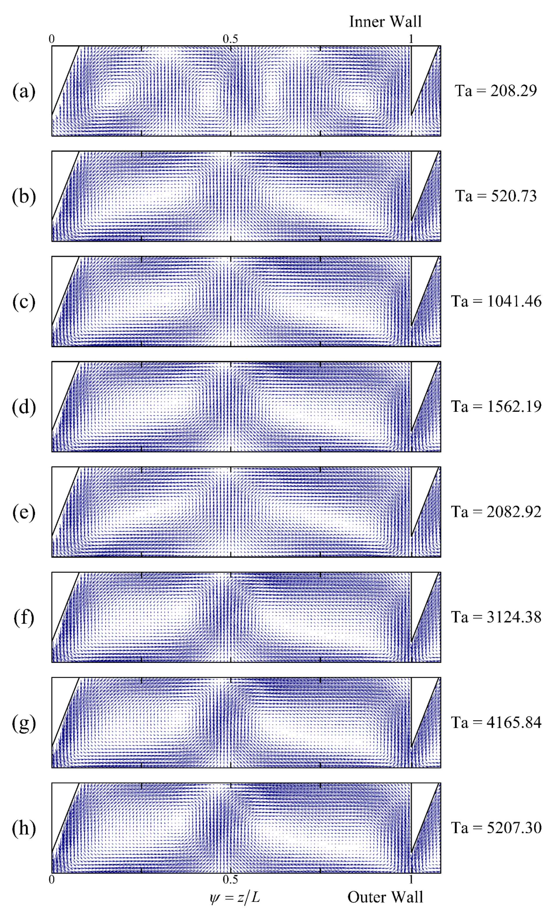
3.2. Vortex Structure without Axial Flow

This paper uses the PIV method to investigate the flow structure within a ribbed TCR under non-axial flow conditions (Rez = 0). Figure 4 compares the instantaneous and time-averaged flow fields within the ribbed TCR at two speeds. The figure shows that the difference between the instantaneous and time-averaged flow field for Ta = 1041.46 and Ta = 3125.38 is minimal, while the Taylor vortex structure is the same. This indicates that both flow fields essentially have the same effect on the flow structure and the scale definition of the vortex within the TCRs. Therefore, a time-averaged flow field is used here in all subsequent studies of TCR flow structure.
Interestingly, the rib structure does not affect the periodic flow field structure in the annular gap region of the TCR. In fact, the flow structure becomes more stable due to the rib constraint. The presence of ribs results in fewer fluctuations in the velocity field. The boundary of the Taylor vortex cannot vibrate on a large scale, due to the limitation of the rib, so the difference between the instantaneous and time-averaged flow fields in the ribbed TCR is minimal. This phenomenon demonstrates that the introduction of ribs creates a more stable and controllable flow field and that the stability of the flow structure offers the possibility of controllable performance.
To investigate the effect of ribs in controlling the flow field and the size of the Taylor vortex in TCRs, the effect of the Ta value on the flow structure of the smooth-rotor TCR was first studied. Figure 5 shows the variation of the flow field and Taylor vortex size (area inside the red dashed rectangular box) with Ta in a smooth-rotor TCR and (a)–(h) represent flow structure at different Ta. The dashed box in the figure represents the range of a pair of Taylor vortices, the size of which changes significantly with increasing Ta.
At low Ta, the axial scale of each Taylor vortex is approximately equal to the annular gap width. The size of the Taylor vortex increases irregularly with increasing Ta, due to the flow instability caused by the rotor rotation. The increase in Ta leads to an increase in the centrifugal force acting on the fluid, which, in turn, leads to an increase in the Taylor vortex size. This pattern of a Taylor vortex size increasing with Ta in the smooth-rotor TCR provides inspiration and ideas for controlling Taylor vortex structures.
The analysis of the flow structure of a ribbed TCR shows that two Taylor vortex pairs with opposite rotational directions are fixed between adjacent ribs. The size of the Taylor vortex pairs in a ribbed TCR is constantly equal to the size of the rib spacing chamber. This demonstrates that the introduction of ribs provides a means by which to control the size of the Taylor vortex pairs in the TCRs.
Figure 6 shows the variation of the area of the Taylor vortex pair for a smooth-rotor TCR, where the horizontal coordinate is Ta, and the vertical coordinate is the ratio of the actual Taylor vortex pair area (Si) to the area of the annular gap area that corresponds to twice the annular gap width (S0). Since the area between the ribs is fixed, the area of the Taylor vortex pair for a ribbed TCR does not change according to Ta. The blue horizontal lines in the figure represent the area of the Taylor vortex pair that can be formed for different rib spacings, respectively. The intersection of the lines with the curves indicates that the area of the ribbed TCR and the smooth-rotor TCR vortex pairs are equal at this Ta. Given this finding, the presence of the ribs stretches the Taylor vortex when the Ta value is less than the intersection value, while the presence of the ribs compresses the size of the Taylor vortex when the Ta value is greater than the intersection value. As can be seen in Figure 6, in the Ta range studied in this paper, the ribs can only compress the size of the Taylor vortex when L/e < 1.5, while they can only stretch the Taylor vortex when L/e > 3. Control of the flow field in the TCR also means control of the flow structure, and appropriate rib spacing can accurately control the Taylor vortex size in the TCR.
The presence of ribs provides additional radial contact surfaces, which cause a Taylor vortex size variation pattern in a ribbed TCR that is completely different from a conventional TCR. To investigate the effect of rib spacing on flow structure control, a wide range of rib spacings was studied in this paper, ranging from 4 mm to 20 mm. This corresponds to a ratio of rib spacing to annular gap width (L/e) in the range of 1.0–5.0, which is an extensive range and ensures the adequacy of the study.
Figure 7 illustrates the effect of rib spacing on the Taylor vortex structure for a Taylor number of 208.29. Although the figure only shows the flow field between two ribs, the actual flow field is highly repetitive, due to the symmetrical distribution of the ribs on the rotor. When the rib spacing is less than or equal to 3 times the annular gap width (L/e ≤ 3), two Taylor vortices always form between adjacent ribs, with the up vortex rotating clockwise and the down vortex rotating counterclockwise. As the rib spacing increases in this interval, only the axial dimensions of the Taylor vortex will change. At L/e = 3.5, two pairs of Taylor vortices are formed between the ribs, with the larger vortex closer to the ribs and the smaller vortex closer to the centerline. At L/e = 5, three pairs of Taylor vortices are formed between the ribs, with the two pairs near the top and bottom ribs being larger than the pair above and below the centerline. The ribs influence the Taylor vortex structure, with the two vortex pairs near the ribs being stretched. It was found that the total number of Taylor vortices between the ribs is always an even number, due to the opposite rotation directions of the adjacent vortices. By adjusting the rib spacing, the size of the Taylor vortex can be significantly stretched or compressed, but there is a limit to the stretching phenomenon beyond which the Taylor vortex will split into more vortex pairs. Therefore, to achieve accurate control of the size of all Taylor vortices within the TCR by varying the rib spacing, it is necessary to ensure that L/e ≤ 3, which results in only one pair of Taylor vortices being formed between the ribs.
In order to further investigate the effect of rib spacing on the Taylor vortex structure, the Taylor vortex structure within each rib spacing at different Ta was investigated separately. When the rib spacing is in the low interval (1 ≤ L/e ≤ 1.5), the ribs have a significant effect on reducing the size of the Taylor vortex pairs relative to a smooth-rotor TCR. The rib spacing in the medium interval (1.5 < L/e ≤ 3) allows for the formation of a single pair of Taylor vortices between the ribs, with little effect from increasing Ta. The high interval (3 < L/e ≤ 4) also forms a single pair of vortices between the ribs, but the number of pairs increases with increasing Ta. In the highest interval (4 < L/e ≤ 5), three pairs of Taylor vortices can be formed between the ribs at low Ta, but an increase in Ta transforms them into two pairs.
When the rib spacing is between 1 and 1.5 times the size of the gap (L/e ≤ 1.5), the presence of ribs only results in a reduction in the size of Taylor vortex pairs relative to a smooth-rotor TCR, across the range of Ta values studied. Figure 8 shows that two Taylor vortices can be formed between the ribs, with the red curve marking the boundary between the up and down vortices. At Ta = 208.29, the two Taylor vortex pairs between the ribs are roughly equal in size, with an area comprising approximately 50% of the area between the ribs. As the Ta value increases, the area of the down vortex gradually decreases, while the area of the up vortex increases, causing the size of the down vortex to decrease to a minimum at a high Ta value, where its size is approximately equal to the distance between the rib edge and the outer cylinder. This phenomenon arises because when the rib spacing is small and the vortex size is small, the additional wall effect of the ribs becomes significant. The lower ribs are in contact with the fluid on an inclined plane, causing the down vortex to be compressed in order to conform to the direction of fluid flow.
When the rib spacing is between 1.5 and 3 times the gap (1.5 < L/e ≤ 3), as shown in Figure 9, a pair of Taylor vortices can be formed between the ribs at any Ta value, while an increasing Ta value has little effect on the Taylor vortex structure when the scale of the vortex is large, and the effect of wall effects can be ignored.
When the rib spacing is between 3 and 4 times the gap (3 < L/e ≤ 4), as shown in Figure 10, at Ta = 208.29, two pairs of vortices can be formed between the ribs. By increasing the Ta value, the two pairs of vortices are transformed into a single pair, and increasing the Ta value further does not change the Taylor vortex structure.
When the rib spacing is between 4 and 5 times the gap (4 < L/e ≤ 5), as shown in Figure 11, three pairs of Taylor vortices can form between the ribs at low Ta. Increasing the Ta eventually transforms them into two pairs, with each pair of Taylor vortices elongated near the ribs, while the size of the Taylor vortex near the center line is approximately equal to the annular gap width. In summary, the contact surface between the ribs and the fluid has a more significant influence on the flow structure within the TCR, and the closer the fluid is to the ribs, the greater the wall effect. The rib spacing of the ribs can be varied to achieve compression or stretching of the Taylor vortex under certain conditions, but there is a range of elasticity; a lesser rib spacing will result in too strong a rib-wall effect, causing an extreme imbalance of the Taylor vortex pairs between the ribs, while a greater rib spacing will prevent the Taylor vortex flow from responding to the elongation behavior of the increased rib spacing and will instead form more than one pair of Taylor vortices. Both extremes do not allow for efficient control of the flow structure of the TCR. Therefore, it is essential to design ribbed TCRs with a rib spacing that is within a suitable range (1.5 < L/e ≤ 3).

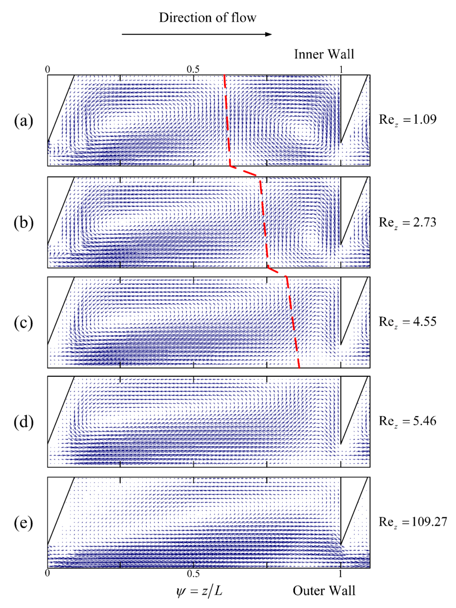
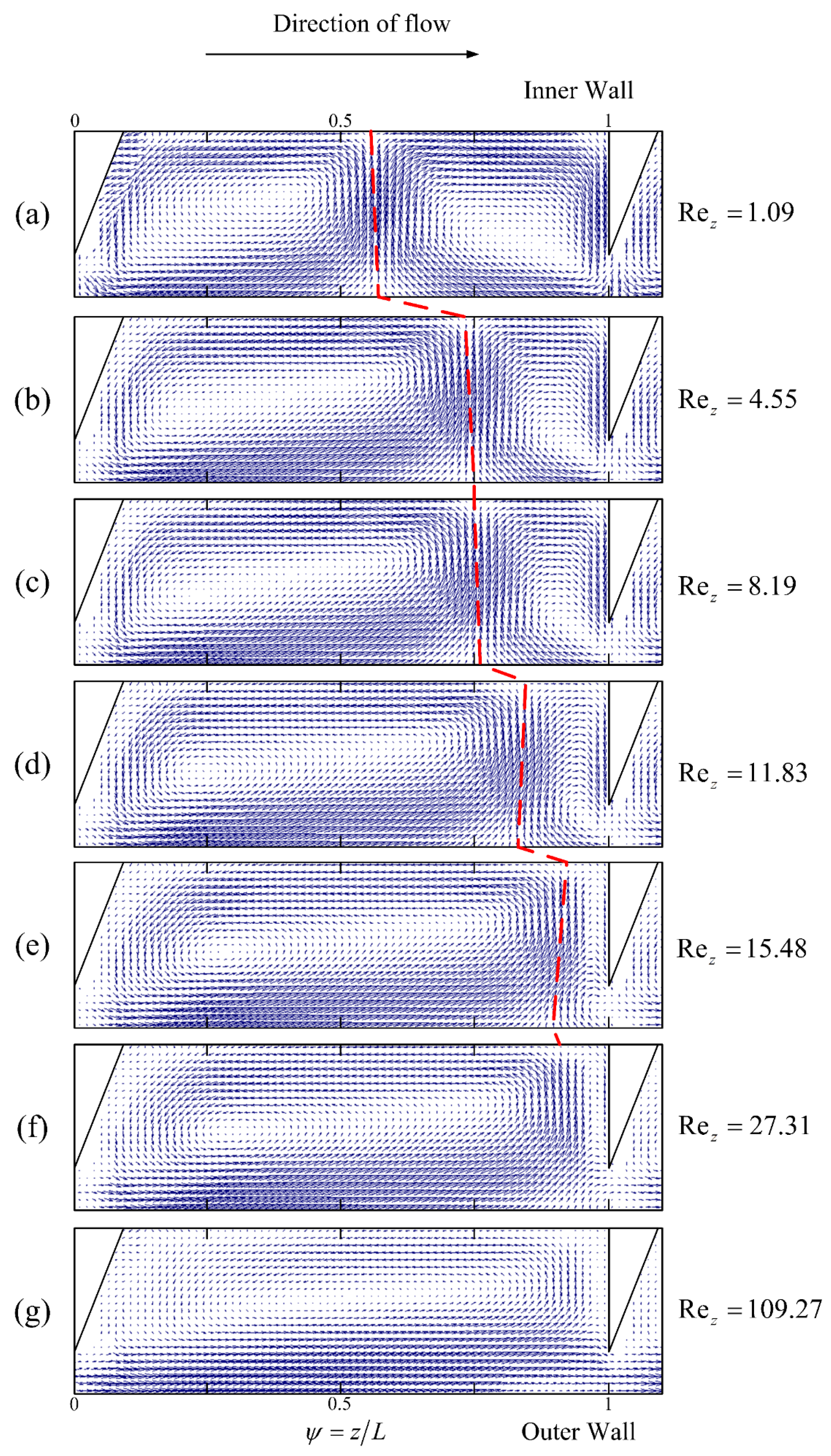
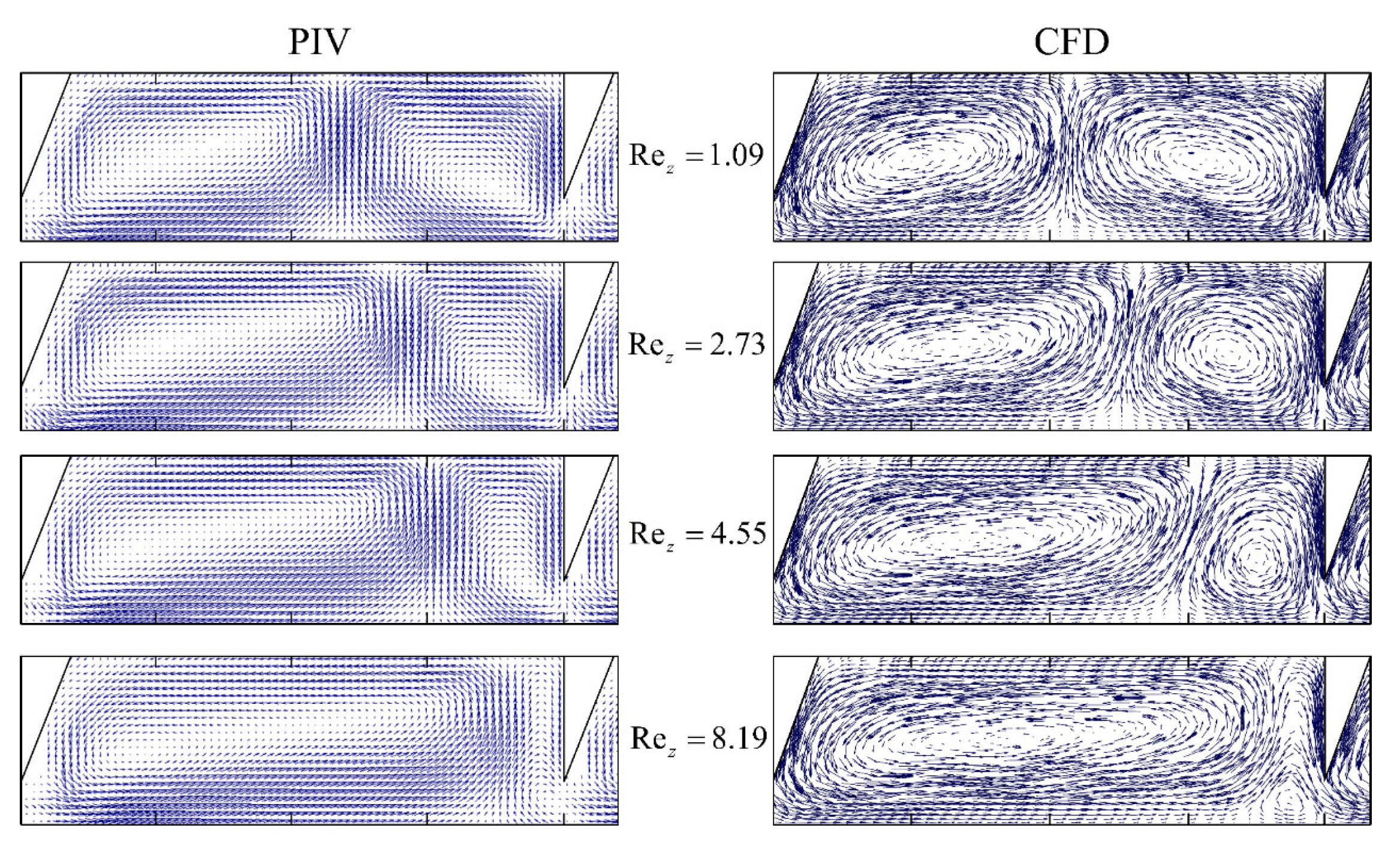
3.3. Vortex Structure with Axial Flow

The flow structure of ribbed TCRs is significantly influenced by axial flow; due to the additional wall surface provided by the ribs, the changes in Taylor vortex structure induced by axial flow are necessarily different from those of conventional TCRs. This study examines the main factors affecting the Taylor vortex structure, including the Taylor number, rib spacing, and rib width. The Taylor number affects the magnitude of centrifugal force and the associated flow instability within the fluid, while rib spacing and width, two important rib structure parameters, directly impact the wall boundary conditions of the Taylor vortex [23]. In smooth-rotor TCRs with axial flow, the annular Taylor vortex in the annular gap region remains unchanged from its non-axial flow state at low axial Reynolds numbers, with the Taylor vortex drifting along the annular gap at a fixed axial flow. At high axial Reynolds numbers, the Taylor vortex exhibits a clear winding state, with the Taylor vortex spiraling in space. In either case, the Taylor vortex displays greater instability in space than in the absence of axial flow. The introduction of ribs significantly limits drift at low axial flow and helical winding at high axial flow. The additional wall effect provided by the ribs partially converts the axial motion of the vortex into a mutual squeezing deformation of the Taylor vortex pairs between the ribs, allowing for the analytical study of flow structure within ribbed TCRs by characterizing the relative size of the two Taylor vortices between the ribs.
This section explores the influence of the axial Reynolds number (Rez) on the Taylor vortex structure, using the PIV approach. Figure 12, Figure 13, Figure 14 and Figure 15 depict the effect of Rez on the Taylor vortex structure at different Ta values for a rib spacing of 12 mm (L/e = 3). As shown in Figure 12, Figure 13, Figure 14 and Figure 15 (The red dashed line represents the boundary line of the Taylor vortex pair), when the Rez value is close to zero, the up and down vortex areas are almost equal, occupying around half the area of the meridional surface between adjacent ribs, regardless of Ta. As Rez increases in the direction of fluid flow, the up vortex is compressed axially, while the down vortex is stretched. The compression and stretching effects become more pronounced as Rez further increases, and the minimum axial width of the up vortex is equal to the distance between the edge of the rib and the outer cylinder. When the Rez value reaches a certain limit, the area of the up vortex is reduced to zero, and the down vortex occupies most of the inter-rib area (as depicted in Figure 12d, Figure 13f, Figure 14f and Figure 15f). At this point, the area of the down vortex is slightly less than the inter-rib area (about 90% of the inter-rib area), due to the partial bending motion of the fluid in the upper rib area. As Rez continues to increase to an extreme value (Rez = 109.27), the down vortex fills the entire rib area, resulting in there being only one vortex between the ribs. At this stage, the mainstream role dominates, and the role of the Taylor vortex is minimal. The flow in the annular gap gradually approaches laminar flow and the turbulence is low. The presence of ribs restricts the drift of the annular Taylor vortex at low axial flows and spiral winding at high axial flows, which explains the variation in the Taylor vortex. The additional contact surface provided by the ribs partially converts the axial motion of the vortex into the mutual extrusion deformation of the Taylor vortex pairs between the ribs. Therefore, the flow within a ribbed TCR with axial flow differs significantly from that in the scenario without ribs, and there is a shift in flow pattern within the ribbed TCR as the axial flow increases. At any Ta, there is a threshold value of Rez beyond which the flow pattern in the TCR changes from a double-vortex pattern between the ribs to a single-vortex pattern; therefore, we define this threshold value as the critical axial Reynolds number for the single/double vortex transition in a ribbed TCR (Rezcr). Although the flow pattern transitions within the TCR are consistent across the Ta values, Rezcr is different. As shown in Figure 12, when Ta = 208.29, the up vortex reaches a minimum at Rez = 4.55 and disappears entirely by 5.46; therefore, the Rezcr value is between 4.55 and 5.46. At Ta = 1041.46, as shown in Figure 13, the up vortex decreases to a minimum at 8.19 and only disappears entirely by 18.21; therefore, the value of Rezcr is less than 18.21. Similarly, for Ta = 2082.92, Rezcr is less than 27.31, and for Ta = 3124.38, Rezcr is less than 31.87. The larger the Ta value, the flatter the change in the area of the up and down vortices as Rez increases, and the larger the value for Rezcr. This phenomenon can be explained by the fact that an increase in Ta leads to an increase in the centrifugal forces within the flow field, which, in turn, increases the instability of the flow, whereas axial flow tends to weaken this effect and stabilize the flow field; therefore, the larger the Ta, the greater the resistance that must be overcome by the flow pattern transformation, and the greater Rezcr required. Thus, ribbed TCRs have different operating intervals of double-vortex flow patterns at different Ta values (0 < Rez < Rezcr); in addition, the presence of a flow pattern transition makes it necessary to ensure that the reactor is under the same flow pattern when evaluating TCR performance, which is very different from that seen in conventional TCRs.
To quantitatively characterize the effect of the Reynolds number (Rez) on the Taylor vortex structure, we used the dimensionless vortex area, as mentioned in Section 3.1, to analyze the vortex pairs between the ribs. Figure 16 shows the effect of Rez on the up and down vortex sizes for ribbed TCRs, i.e., 8 mm (L/e = 2) and 12 mm (L/e = 3), at different Taylor numbers (Ta). For all conditions, at very low Rez values (minimal axial flow), the up and down vortex areas are comparable, with the up vortex area being slightly smaller than the down vortex area, both occupying approximately half the area of the inter-rib region. At the minimum value of Rez at Ta = 3124.38 for a rib spacing of 8 mm, the up and down vortex areas are equal in axial length, both being half the rib spacing, but the area of the down vortex is slightly larger, due to the removal of one rib. As the Rez value increases, the up vortex area decreases monotonically, and the down vortex area increases to the same extent. The sum of the two areas must equal that of the inter-rib area, meaning that the curves of the up and down vortex area changes are always symmetrical at about Si/SR = 0.5. As Rez continues to increase, the areas of the up and down vortices reach a minimum and maximum, respectively, and remain constant. The transition from a two-vortex flow to a single-vortex flow occurs at the junction of the monotonically increasing/decreasing region of the curve and the horizontal region, which is denoted by Rezcr.
When the rib spacing is the same, the larger the Ta, the slower the rate of change of the vortex area with increasing Rez, and the larger the Rezcr corresponding to the transition to the horizontal region. Comparing Figure 16a,b, it is evident that the rib spacing has a significant effect on the vortex area variation. The Rez range for the flow pattern transition at different Ta values ranges from 4–14 Rez for 8 mm spacing of TCRs and from 8–32 Rez for 12 mm spacing of TCRs. The size of the Taylor vortex decreases as the rib spacing decreases, causing the boundary effects of the additional rotating wall provided by the ribs to have a greater impact. Additionally, a smaller rib spacing requires less axial flow to resist the centrifugal forces and achieve flow-pattern transition. Consequently, rib spacing plays a crucial role in the flow transition of a ribbed TCR. An increase in rib spacing results in a larger Rezcr and a wider range of double-vortex operations for the same Ta.
In the above discussion, the rib width (d) was fixed at 3 mm, while rib width was also a significant factor affecting the vortex structure within the ribbed TCR. Figure 17 and Figure 18 illustrate the variation in the Taylor vortex structure and vortex area for two different rib widths (d) at a Ta of 3124.38. When comparing the vortex structure and the change in vortex area, it is evident that the rate of vortex compression/stretching is flatter when d is equal to 1 mm, and the area of the up and down vortices linearly decreases and increases with Rez. Moreover, there is no change in the flow pattern at Rez   <   31.87 . However, when d is equal to 3 mm, the vortex structure changes more rapidly and converts from a double-vortex flow to a single-vortex flow. The reason for this phenomenon has been explained by Deng [26]. In the absence of axial flow, a small vortex is easily generated near the rib’s edge, with a size equal to the distance between the rib and the outer cylinder. Upon introducing axial flow, the size of the up vortex size remains consistent across a wide range of Rez and does not decrease to the size of the interval between the rib and the outer cylinder. These findings suggest that a smaller rib width leads to a wider TCR operating range in the double-vortex flow. However, it is worth noting that the original purpose of introducing ribs was to weaken the axial diffusion between the annular Taylor vortex since a small rib width also weakens this effect. Hence, it is essential to choose a suitable rib width that balances the advantages and the disadvantages.

3.4. Critical Axial Reynolds Number for Flow Pattern Transformation

Based on the above analysis, it can be inferred that the Taylor vortex in the ribbed TCR shows a gradual compression of the up vortex and stretching of the down vortex over the entire ribbed interval as the Rez value increases. This results in a change in the flow pattern from double-vortex flow to single-vortex flow. The axial Reynolds number corresponding to the flow pattern transition is defined as the critical axial Reynolds number (Rezcr). The accurate determination of Rezcr can only be estimated from Rez before and after the flow pattern change since it cannot be obtained with absolute accuracy. Hence, the accuracy of Rezcr depends on the resolution of Rez. A smaller interval for Rez used in the study is crucial for achieving greater precision in measuring Rezcr. However, considering the limitations of adjustable flow rate and pumping accuracy in the experiments, CFD numerical simulations were employed to determine the flow pattern transition of Rezcr within the ribbed TCR.

3.4.1. Validation of the CFD Results

To ensure the accuracy and reliability of the CFD numerical simulations, the velocity field results were validated using the PIV method. The velocity distributions on the radial horizontal line, corresponding to the vortex center of the up and down vortices, and on the center line of the annular gap were compared under the same conditions. The axial velocity, V, on the vortex center line and the radial velocity, U, on the center line of the annular gap were chosen as the objects of velocity distribution and were made dimensionless with the inner cylinder velocity, ωRi, respectively. The average velocity fields obtained by the PIV and CFD simulations with two different Taylor numbers (Ta 1041.46 and 3124.38) were compared in Figure 19. The results show that the PIV data and numerical simulations for the relevant velocity distributions at all positions for both Ta values are in good agreement, with the largest errors occurring at the inner and outer cylinder walls.
Although the numerical simulations use a no-slip boundary condition, the axial velocities at the inner and outer cylinder walls (r/e of 0 and 1) and the radial velocities at the rib walls (z/L of 0 and 1) are zero, while the results obtained from the PIV experiments are not zero. This deviation may be due to the insufficient measurement resolution of the PIV method. Furthermore, the comparison of the Taylor vortex structure changes obtained by PIV and CFD at different axial Reynolds numbers, as shown in Figure 20, also validates the reliability of the numerical simulations used to determine the critical Reynolds number for flow pattern transition.

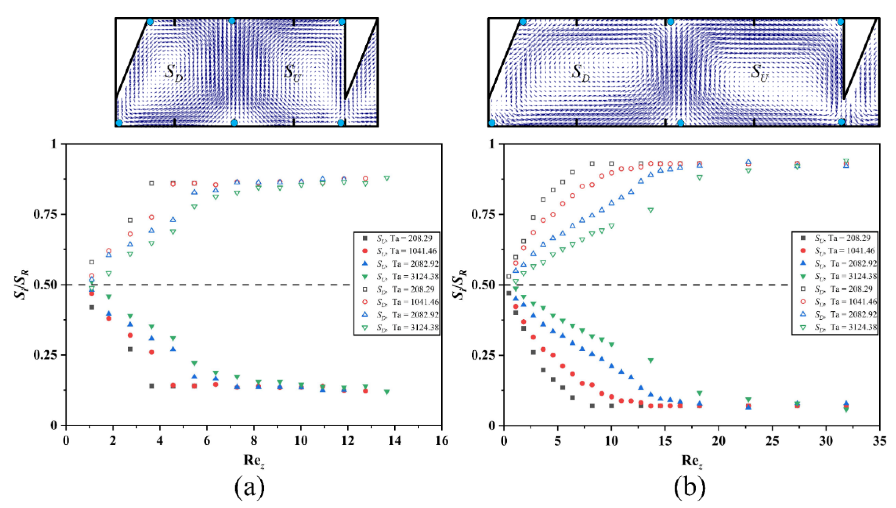
3.4.2. Vortex Identification Method

To accurately determine the threshold for the transition from a double to a single vortex between the ribs, it is necessary to first identify the Taylor vortex. The Ω method chosen to identify the vortex uses a parameter with a value of between 0 and 1, where a value of 1 indicates rigid body rotation while a value greater than 0.5 indicates a higher proportion of the antisymmetry tensor, B, than the symmetry tensor, A. A threshold value of 0.52 is typically used for vortex identification, but the threshold can be adjusted as needed. In this study, the threshold of Ω was set to 0.6.
Ω is defined by Equation (12) [33]:
Ω = B F 2 A F 2 + B F 2 + ε
where ε is a factor preventing the denominator from being zero, and its value can be estimated by the following formula:
ε = max B F 2 A F 2 1000 .
The Ω distribution of the different axial Reynolds numbers obtained through CFD is shown in Figure 21. As the Rez value increases, the vortex intensity gradually decreases, and the vortex core moves upward, indicating the stretching of the down vortex and the compression of the up vortex. When Rez crosses from 30 to 30.5, the up-vortex core ultimately disappears. At this point, it has been determined that the flow changes from a double-vortex flow pattern to a single-vortex flow pattern. The flow pattern change lies between the Rez values of 30 and 30.5 and the axial Reynolds number resolution of 0.5 is the finest resolution chosen for this study. Therefore, the midpoint of this range, i.e., 30.25, can be defined as the Rezcr. Overall, the validation of the CFD simulations with the PIV model and the use of a reliable vortex identification method allowed for an accurate analysis of the flow pattern transition in ribbed TCRs. The results provide important insights into the flow characteristics and transition mechanisms in these types of systems, which can be useful in the design and optimization of TCRs for various applications.

3.4.3. Estimation of the Critical Axial Reynolds Number

To estimate the critical axial Reynolds number, we used the Ω vortex identification method with a threshold of 0.6 for the complete disappearance of the up vortex and a minimum step of 0.5 for Rez. The values of Rez used in the two adjacent simulations to achieve the flow pattern transition were used to determine the estimated interval (Rezcrmin, Rezcrmax) for the critical Reynolds number (Rezcr). The median value of the interval was then used as the estimated Rezcr, using Equation (14).
Re z c r = Re z min + Re z max 2
In this study, a rib width of 3 mm was chosen, and it was found that the smaller the rib width, the larger the Rezcr for the flow transition. Therefore, in a TCR with a rib width of less than 3 mm, the flow pattern will also be a double vortex when the Rez value is smaller than the Rezcr value, obtained using a rib width of 3 mm in the same conditions. Rezcr in a ribbed TCR was investigated in relation to Ta and rib spacing of L/e in this study. The results of the CFD simulations were used to estimate the Rezcr value for each Ta and L/e, as shown in Figure 22. As is consistent with the previous results for the Taylor vortex structure, Rezcr was found to be positively proportional to Ta and inversely proportional to L/e. Therefore, to obtain a wider operating interval of the double-vortex flow pattern, an increase in rotational speed or rib spacing is required. However, increasing the rotational speed may result in higher energy consumption and flow instability at high speeds, while increasing the rib spacing may go against the original intention of controlling the flow field. Therefore, it is necessary to balance the operating range and the performance requirements to optimize the rib structure and obtain the most suitable TCR configuration for the specific application.

3.4.4. Critical Reynolds Number Correlation

The results in Figure 22 demonstrate a strong correlation between Rezcr, Ta, and L/e, and suggest that Ta and L/e have an interactive effect on the prediction of the effect of Rezcr. To capture this interaction, we used a binary polynomial fit with an interaction term for Ta and L/e, as given by Equation (15), with a correlation coefficient, R2, of 0.997. Equation (15) can be used to predict the critical Reynolds number for the flow transition in ribbed TCRs with a rib width of 3 mm, given the values of Ta and L/e. By using this equation, it is possible to optimize the rib structure and operating conditions of a TCR to achieve the desired flow pattern and mixing performance, while minimizing the energy consumption and flow instability.
Re z c r = 0.40 Ta ¯ 2 0.80 Ta ¯ + 3 . 3 Ta ¯ L e 0.038 L e 2 + 0.97 L e + 0.66
Ta ¯ = Ta 1000
The fitted surfaces for Rezcr as a function of Ta and L/e are shown in Figure 23. Rezcr exhibits a quadratic relationship with both Ta and L/e, with a low quadratic term coefficient for L/e of −0.038, which has a negligible effect and is essentially linear. The interaction term coefficient is 3.3, indicating a strong interaction between Ta and L/e that cannot be ignored. To verify the accuracy of the empirical correlation formula for predicting Rezcr, the intervals of Rezcr predicted by the formula were compared with the intervals of Rezcr obtained from the PIV experiment. Figure 24 shows that the predicted values of Rezcr correspond well with the experimental points, with almost all predicted values falling within the short vertical lines connecting the experimental points. This demonstrates the accuracy and reliability of the empirical correlation for predicting Rezcr in ribbed TCRs with a rib width of 3 mm.

4. Conclusions

For this paper, we investigated the flow structure and pattern transition found within a ribbed TCR, using PIV experiments and CFD numerical simulations, and achieved good agreement between the experimental and numerical simulation results. We used the third-generation method to identify the vortices and determine the critical axial Reynolds number for flow pattern transition, which we correlated with the Taylor number and rib spacing. The main conclusions of this study are:
(1)
The ribbed TCR enables control of the flow field structure while maintaining the symmetry of the flow field, due to the outer cylindrical surface provided by the ribs. Under certain conditions, a Taylor vortex pair can form between the ribs, with the down vortex rotating clockwise and the up vortex rotating counterclockwise. The area around the ribs is the outflow zone, and the area where the two vortices meet is the inflow zone.
(2)
We investigated the variations in the Taylor vortex structure with Ta within a ribbed TCR in the absence of axial flow. We found that the axial dimension of the Taylor vortex can be controlled by adjusting the rib spacing, which can be summarized into four different conditions according to the size of the rib spacing. When L/e is less than 1.5, the Taylor vortex that forms between the ribs is more sensitive to the wall effect of the ribs, and the up vortex is gradually compressed as the rotor speed increases. When L/e is between 1.5 and 3, a stable Taylor vortex pair can form between the ribs that are less susceptible to the boundary effect of the rib wall. When L/e is greater than 3 and less than 4, two pairs of Taylor vortices can form between the ribs, which can be converted into a pair by increasing the speed, while for L/e greater than 4, three pairs of Taylor vortices can be formed between the ribs, which can be converted into two pairs by increasing the Ta value.
(3)
The axial Reynolds number Rez greatly impacts the Taylor vortex structure within the ribbed TCR. As the axial Reynolds number increases, the up vortex appears to be compressed, and the down vortex appears to be stretched; when a specific critical value is reached, the double-vortex flow pattern between the ribs is transformed into a single vortex. The operating parameter Ta and the structural parameters (L, d) strongly influence the transition rate and the critical point. Larger critical axial Reynolds numbers (Rezcr) and lower transition rates are observed when a higher Ta value, larger rib spacing, and smaller rib widths are utilized.
(4)
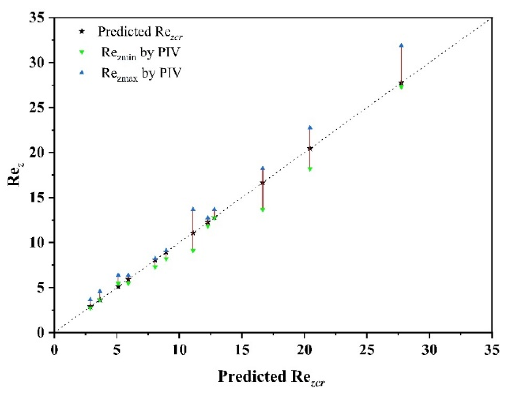
By using the Ω method to identify the Taylor vortex within the TCR and setting 0.6 as the threshold for the flow pattern transition, we obtained a Rezcr value with greater accuracy via CFD methods for the various rib spacings and Ta values. We correlated Rezcr with Ta and L/e via binary polynomial fitting and found that Rezcr is strongly correlated with Ta and L/e. The empirical correlation equation that we have developed shows strong predictive power, which we validated with the experimental results of PIV.
This study provides valuable insight into the vortex structure and flow transition in ribbed TCRs, which can promote the development of future research into the enhancement of heat and mass transfer in ribbed TCRs.

Supplementary Materials

The following are available online at https://www.mdpi.com/article/10.3390/pr11072162/s1. Supporting information is available on meshing, boundary conditions, solution setup and mesh independence test. Figure S1: Physical model and model mesh of ribbed TCR., Figure S2: Grid independence for TCR. (a) Volume average tangential velocity; (b) Average shear stress on Rotor.

Author Contributions

Conceptualization, J.T.; methodology, C.W.; software, C.W.; validation, J.T. and C.W.; formal analysis, J.T.; data curation, F.L.; writing—original draft preparation, J.T.; writing—review and editing, C.W.; supervision, X.Y.; project administration, R.W. All authors have read and agreed to the published version of the manuscript.

Funding

This research received no external funding.

Data Availability Statement

Data sharing is not applicable to this article as no datasets were generated or analyzed during the current study.

Conflicts of Interest

The authors declare no conflict of interest.

Nomenclature

CFDComputational fluid dynamics
dRib width, mm
eAnnular gap width, mm
hRib edge thickness, mm
lRotor length, mm
LRib spacing, mm
NNumber of regions
PPoint
R2Regression coefficient
RiInner cylinder radius, mm
RoOuter cylinder radius, mm
RezAxial Reynolds number
RezcrThe critical axial Reynolds number
RSMReynolds stress model
SArea of the specific region, m2
TaTaylor number
TCRTaylor–Couette reactor
TCFTaylor–Couette flow
uaxThe axial flow velocity, m/s
VVelocity, m/s
(r, z)Dimensional coordinates
Greek
ε turbulent kinetic energy dissipation rate, m2/s3
ϕFactor ϕ, characterizing the relationship between the local energy dissipation rate and the volume-averaged energy dissipation rate, which is introduced as a constant value
ωRotation speed of rotor, rad/s
νKinematic viscosity, m2/s
ρThe density of liquid, kg/m3
(ψ, ξ)Dimensionless coordinates

References

  1. Jung, T.; Kim, W.S.; Choi, C.K. Effect of monovalent salts on morphology of calcium carbonate crystallized in couette–taylor reactor. Cryst. Res. Technol. J. Exp. Ind. Crystallogr. 2005, 40, 586–592. [Google Scholar] [CrossRef]
  2. Aljishi, M.F.; Ruo, A.; Park, J.H.; Nasser, B.; Kim, W.; Joo, Y.L. Effect of flow structure at the onset of instability on barium sulfate precipitation in taylor–couette crystallizers. J. Cryst. Growth 2013, 373, 20–31. [Google Scholar] [CrossRef]
  3. Hong, S.B.; Jeong, J.; Kang, H.G.; Seo, D.; Cha, Y.; Jeon, H.; Lee, G.Y.; Irshad, M.; Kim, D.H.; Hwang, S.Y. Fast and scalable hydrodynamic synthesis of mno2/defect-free graphene nanocomposites with high rate capability and long cycle life. ACS Appl. Mater. Interfaces 2018, 10, 35250–35259. [Google Scholar] [CrossRef]
  4. Lee, S.; Park, S. Enhanced dispersion and material properties of multi-walled carbon nanotube composites through turbulent taylor-couette flow. Compos. Part A Appl. Sci. Manuf. 2017, 95, 118–124. [Google Scholar] [CrossRef]
  5. Haut, B.; Amor, H.B.; Coulon, L.; Jacquet, A.; Halloin, V. Hydrodynamics and mass transfer in a couette–taylor bioreactor for the culture of animal cells. Chem. Eng. Sci. 2003, 58, 777–784. [Google Scholar] [CrossRef]
  6. Qiao, J.; Yan, W.; Teoh, J.H.; Tong, Y.W.; Wang, C. Experimental and computational studies of oxygen transport in a taylor-couette bioreactor. Chem. Eng. J. 2018, 334, 1954–1964. [Google Scholar] [CrossRef]
  7. Sorg, R.; Tanzeglock, T.; Soos, M.; Morbidelli, M.; Périlleux, A.; Solacroup, T.; Broly, H. Minimizing hydrodynamic stress in mammalian cell culture through the lobed taylor-couette bioreactor. Biotechnol. J. 2011, 6, 1504–1515. [Google Scholar] [CrossRef] [PubMed]
  8. Färber, T.; Riechert, O.; Zeiner, T.; Sadowski, G.; Behr, A.; Vorholt, A.J. Homogeneously catalyzed hydroamination in a taylor–couette reactor using a thermormorphic multicomponent solvent system. Chem. Eng. Res. Des. 2016, 112, 263–273. [Google Scholar] [CrossRef]
  9. Behr, A.; Vorholt, A.J.; Färber, T.; Behr, A.; Vorholt, A.J. Hydroamination and telomerisation of β-myrcene. In Homogeneous Catalysis with Renewables; Springer: Berlin/Heidelberg, Germany, 2017; pp. 177–189. [Google Scholar]
  10. Bernstein, G.J.; Grosvenor, D.E.; Lenc, J.F.; Levitz, N.M. Development and Performance of a High-Speed, Long-Rotor Centrifugal Contactor for Application to Reprocessing Lmfbr Fuels; Argonne National Laboratory: Argonne, ILL, USA, 1973. [Google Scholar]
  11. Haim, D.; Pismen, L.M. Performance of a photochemical reactor in the regime of taylor-grtler vortical flow. Chem. Eng. Sci. 1994, 49, 1119–1129. [Google Scholar] [CrossRef]
  12. Sczechowski, J.G.; Koval, C.A.; Noble, R.D. A taylor vortex reactor for heterogeneous photo-catalysis. Chem. Eng. Sci. 1995, 50, 3163–3173. [Google Scholar] [CrossRef]
  13. Sengupta, T.K.; Kabir, M.F.; Ray, A.K. A taylor vortex photocatalytic reactor for water purification. Ind. Eng. Chem. Res. 2001, 40, 5268–5281. [Google Scholar] [CrossRef]
  14. Forney, L.J.; Pierson, J.A. Optimum photolysis in taylor–couette flow. AICHE J. 2003, 49, 727–733. [Google Scholar] [CrossRef]
  15. Dutta, P.K.; Ray, A.K. Experimental investigation of taylor vortex photocatalytic reactor for water purification. Chem. Eng. Sci. 2004, 59, 5249–5259. [Google Scholar] [CrossRef]
  16. Lee, S.; Lueptow, R.M. Rotating reverse osmosis: A dynamic model for flux and rejection. J. Membr. Sci. 2001, 192, 129–143. [Google Scholar] [CrossRef]
  17. Forney, L.J.; Pierson, J.A.; Ye, Z. Juice irradiation with taylor-couette flow: UV inactivation of Escherichia coli. J. Food Prot. 2004, 67, 2410–2415. [Google Scholar] [CrossRef] [PubMed]
  18. Krintiras, G.A.; Diaz, J.G.; Van Der Goot, A.J.; Stankiewicz, A.I.; Stefanidis, G.D. On the use of the couette cell technology for large scale production of textured soy-based meat replacers. J. Food Eng. 2016, 169, 205–213. [Google Scholar] [CrossRef] [Green Version]
  19. Nemri, M.; Cazin, S.; Charton, S.; Climent, E. Experimental investigation of mixing and axial dispersion in taylor–couette flow patterns. Exp. Fluids 2014, 55, 1769. [Google Scholar] [CrossRef] [Green Version]
  20. Richter, O.; Hoffmann, H.; Kraushaar-Czarnetzki, B. Effect of the rotor shape on the mixing characteristics of a continuous flow taylor-vortex reactor. Chem. Eng. Sci. 2008, 63, 3504–3513. [Google Scholar] [CrossRef] [Green Version]
  21. Richter, O.; Menges, M.; Kraushaar-Czarnetzki, B. Investigation of mixing in a rotor shape modified taylor-vortex reactor by the means of a chemical test reaction. Chem. Eng. Sci. 2009, 64, 2384–2391. [Google Scholar] [CrossRef]
  22. Lueptow, R.M.; Docter, A.; Min, K. Stability of axial flow in an annulus with a rotating inner cylinder. Phys. Fluids A Fluid Dyn. 1992, 4, 2446–2455. [Google Scholar] [CrossRef] [Green Version]
  23. Wereley, S.T.; Lueptow, R.M. Velocity field for taylor–couette flow with an axial flow. Phys. Fluids 1999, 11, 3637–3649. [Google Scholar] [CrossRef] [Green Version]
  24. Hwang, J.; Yang, K. Numerical study of taylor–couette flow with an axial flow. Comput. Fluids 2004, 33, 97–118. [Google Scholar] [CrossRef]
  25. Deshmukh, S.S.; Joshi, J.B.; Koganti, S.B. Flow visualization and three-dimensional cfd simulation of the annular region of an annular centrifugal extractor. Ind. Eng. Chem. Res. 2008, 47, 3677–3686. [Google Scholar] [CrossRef]
  26. Deng, R.; Yohanes Arifin, D.; Ye Chyn, M.; Wang, C. Taylor vortex flow in presence of internal baffles. Chem. Eng. Sci. 2010, 65, 4598–4605. [Google Scholar] [CrossRef]
  27. Carlos Álvarez, M.; Vicente, W.; Solorio, F.; Mancilla, E.; Salinas, M.; Zenit, V.R. A study of the taylor-couette flow with finned surface rotation. J. Appl. Fluid Mech. 2019, 12, 1371–1382. [Google Scholar] [CrossRef]
  28. Maccioni, L.; Chernoray, V.G.; Bohnert, C.; Concli, F. Particle image velocimetry measurements inside a tapered roller bearing with an outer ring made of sapphire: Design and operation of an innovative test rig. Tribol. Int. 2022, 165, 107313. [Google Scholar] [CrossRef]
  29. Tang, J.; Wang, C.; Liu, F.; Yang, X.; Wang, R. A refractive index-and density-matched liquid–liquid system developed using a novel design of experiments. Processes 2023, 11, 1922. [Google Scholar] [CrossRef]
  30. Deshmukh, S.S.; Vedantam, S.; Joshi, J.B.; Koganti, S.B. Computational flow modeling and visualization in the annular region of annular centrifugal extractor. Ind. Eng. Chem. Res. 2007, 46, 8343–8354. [Google Scholar] [CrossRef]
  31. Sofia, H.; Sébastien, P. Turbulence modeling of torsional couette flows. Int. J. Rotating Mach. 2008, 2008, 635138. [Google Scholar]
  32. Tamhane, T.V.; Joshi, J.B.; Kamachi Mudali, U.; Natarajan, R.; Patil, R.N. Axial mixing in annular centrifugal extractors. Chem. Eng. J. 2012, 207–208, 462–472. [Google Scholar] [CrossRef]
  33. Liu, C.; Wang, Y.; Yang, Y.; Duan, Z. New omega vortex identification method. Sci. China Phys. Mech. Astron. 2016, 59, 684711. [Google Scholar] [CrossRef]
Figure 1. Ribbed TCR structure and the related dimensional definition.
Processes 11 02162 g001
Figure 2. Schematic diagram of the PIV system (a) and the actual experimental setup (b).
Processes 11 02162 g002
Figure 3. Typical flow structure in ribbed TCRs by PIV.
Processes 11 02162 g003
Figure 4. Comparison of the instantaneous velocity field and time-averaged velocity field in a ribbed TCR at different Ta values: (a) instantaneous velocity field, Ta = 1041.46; (b) time-averaged velocity field, Ta = 1041.46; (c) instantaneous velocity field, Ta = 3124.38; (d) time-averaged velocity field, Ta = 3124.38.
Processes 11 02162 g004
Figure 5. Taylor vortex structures within a smooth-rotor TCR at different Ta.
Processes 11 02162 g005
Figure 6. Variation in the Taylor vortex pair area for a smooth-rotor TCR at different Ta values.
Processes 11 02162 g006
Figure 7. Effect of rib spacing (L/e) on the Taylor vortex structure within a ribbed TCR (Rez = 0, Ta = 208.29).
Processes 11 02162 g007
Figure 8. Effect of the Ta on the Taylor vortex structure at L/e = 1.5 (Rez = 0).
Processes 11 02162 g008
Figure 9. Effect of the Ta on the Taylor vortex structure at L/e = 2 (Rez = 0).
Processes 11 02162 g009
Figure 10. Effect of the Ta on the Taylor vortex structure at L/e = 3.5 (Rez = 0).
Processes 11 02162 g010
Figure 11. Effect of the Ta on Taylor vortex structure at L/e = 5 (Rez = 0).
Processes 11 02162 g011
Figure 12. Effect of Rez on the Taylor vortex structure at L/e = 3 (Ta = 208.29).
Processes 11 02162 g012
Figure 13. Effect of Rez on the Taylor vortex structure at L/e = 3 (Ta = 1041.46).
Processes 11 02162 g013
Figure 14. Effect of Rez on the Taylor vortex structure at L/e = 3 (Ta = 2082.92).
Processes 11 02162 g014
Figure 15. Effect of Rez on the Taylor vortex structure at L/e = 3 (Ta = 3124.38).
Processes 11 02162 g015
Figure 16. Variation of the up vortex and down vortex sizes with Rez at different Ta values. (a) L/e = 2; (b) L/e = 3.
Processes 11 02162 g016
Figure 17. Effect of Rez on the Taylor vortex structure at different rib widths (L/e = 2, Ta = 3124.38): (a) d = 1 mm; (b) d = 3 mm.
Processes 11 02162 g017
Figure 18. Variation in the up vortex and down vortex sizes with Rez for different values of d.
Processes 11 02162 g018
Figure 19. Comparison of the velocity profiles obtained from PIV experiments and CFD numerical simulations: (a) up vortex axial velocity profile, Ta = 1041.46; (b) down vortex axial velocity profile, Ta = 1041.46; (c) up vortex axial velocity profile, Ta = 3124.38; (d) down vortex axial velocity profile, Ta = 3124.38; (e) central line for the annular gap radial velocity profile, Ta = 1041.46; (f) central line for the annular gap radial velocity profile, Ta = 3124.38.
Processes 11 02162 g019
Figure 20. Comparison of the Taylor vortex structures of PIV and CFD at different values of Rez.
Processes 11 02162 g020
Figure 21. Ω Distribution at different Rez obtained by CFD (L/e = 3, Ta = 3400).
Processes 11 02162 g021
Figure 22. Critical Reynolds number for flow pattern transition at different Ta and L/e.
Processes 11 02162 g022
Figure 23. Binary polynomial fit surface plot for Rezcr vs. Ta and L/e.
Processes 11 02162 g023
Figure 24. Comparison of the interval obtained by PIV and the predicted value by correlation.
Processes 11 02162 g024
Table 1. Structural parameters of the ribbed TCRs.
Structural ParametersRange
Inner cylinder radius (Ri), mm12.5
Outer cylinder radius (Ro), mm16.5
Annular gap width (e), mm4
Rotor length (l), mm200
Rib spacing (L), mm4–20
Rib width (d), mm1–3
Rib thickness (h), mm1
Number of regions (N)10–50
Disclaimer/Publisher’s Note: The statements, opinions and data contained in all publications are solely those of the individual author(s) and contributor(s) and not of MDPI and/or the editor(s). MDPI and/or the editor(s) disclaim responsibility for any injury to people or property resulting from any ideas, methods, instructions or products referred to in the content.

