Review

The Efficient Utilization of Carbon Dioxide in a Power-to-Liquid Process: An Overview

1
School of Energy Science and Engineering, Nanjing Tech University, Nanjing 211816, China
2
State Key Laboratory of Materials-Oriented Chemical Engineering, College of Chemical Engineering, Nanjing Tech University, Nanjing 211816, China
*
Authors to whom correspondence should be addressed.
Processes 2023, 11(7), 2089; https://doi.org/10.3390/pr11072089
Submission received: 24 June 2023 / Revised: 7 July 2023 / Accepted: 10 July 2023 / Published: 13 July 2023

Abstract

:
As the global climate crisis escalates, reductions in CO2 emissions and the efficient utilization of carbon waste resources have become a crucial consensus. Among the various carbon mitigation technologies, the concept of power-to-liquid (PTL) has gained significant attention in recent years. Considering the lack of a timely review of the state-of-the-art progress of this PTL process, this work aims to provide a systematic summary of the advanced PTL progress. In a CO2 capture unit, we compared the process performances of chemical absorption, physical absorption, pressure swing adsorption, and membrane separation technologies. In a water electrolysis unit, the research progress of alkaline water electrolysis, proton exchange membrane water electrolysis, and solid oxide water electrolysis technologies was summarized, and the strategies for improving the electrolysis efficiency were proposed. In a CO2 hydrogenation unit, we compared the differences of high-temperature and low-temperature Fischer–Tropsch synthesis processes, and summarized the advanced technologies for promoting the conversion of CO2 into high value-added hydrocarbons and achieving the efficient utilization of C1–C4 hydrocarbons. In addition, we critically reviewed the technical and economic performances of the PTL process. By shedding light on the current state of research and identifying its crucial factors, this work is conducive to enhancing the understanding of the PTL process and providing reliable suggestions for its future industrial application. By offering valuable insights into the PTL process, this work also contributes to paving the way for the development of more efficient and sustainable solutions to address the pressing challenges of CO2 emissions and climate change.

1. Introduction

In recent years, global CO2 emissions have been on the rise due to the excessive combustion of coal, petroleum, and other fossil fuels. According to the report of the International Energy Agency, global energy-related CO2 emissions increased to 36.8 billion tons in 2022, which resulted in a series of crises such as global warming, glacier melting, and ocean acidification [1]. Consequently, it is imperative to capture the emitted CO2 in the atmosphere and employ clean renewable energy to replace conventional fossil-based energy. Power-to-liquids (PTL) processes, integrating CO2 capture and water electrolysis technologies, have received widespread attention and are conducive to converting fluctuant renewable energy (e.g., wind and solar energy) into sustainable liquid fuels [2].
Typically, PTL processes consist of three sub-units: CO2 capture, water electrolysis, and CO2 hydrogenation. CO2 capture technologies mainly obtain their CO2 from carbon-intensive industries such as fossil fuel power plants and cement plants, or directly from ambient air [3]. Generally, CO2 capture technologies include pre-combustion, oxygen-rich combustion, and post-combustion. Pre-combustion capture technology captures CO2 derived from the flue gas in power plants or other industrial plants that rely on fossil fuels, which is primarily applicable to high-concentration CO2 (around 30–40%). However, its complex process design and high capital investment are its main limitations. Oxygen-enriched combustion technology reduces the accumulation of particulate matter in flue gas. However, expensive O2 supply systems and its potential safety risks are its main challenges [4]. Post-combustion carbon capture technology refers to the selective enrichment of CO2 from flue gas using chemical or physical methods. Post-combustion capture technology has been widely applied in power plants, steel plants, and chemical plants due to its flexible operation and high technology maturity [5]. Hence, this study mainly focuses on post-combustion capture technology.
H2 is an important raw material that can be produced from fossil energy and renewable energy [6]. More specifically, most H2 is generated via coal gasification and natural-gas-reforming technologies in the industry, which have a low cost, controllable production scale, and high technical maturity. However, energy-intensive and carbon-intensive technologies can result in massive CO2 emissions [7]. Therefore, in recent years, some researchers have been dedicated to developing sustainable and clean H2 generation technologies. Among the various H2 generation technologies, water electrolysis is framed as a promising technology for producing green H2 [8]. This is mainly because water electrolysis technologies eliminate the dependence on fossil energy and show a strong competitiveness compared with traditional H2 generation technologies in terms of CO2 mitigation [9]. Therefore, this work concentrates on water electrolysis technologies for H2 generation. The principle of these technologies is to apply a stable direct current to electrolyze water and obtain H2 on the cathode side and O2 on the anode side. Generally, water electrolysis technologies mainly consist of alkaline water electrolysis, proton exchange membrane water electrolysis, anion exchange membrane water electrolysis, and solid oxide water electrolysis [10]. We will summarize the recent progress of these four water electrolysis technologies in the following content.
CO2 hydrogenation to high value-added liquid fuels and chemicals has been considered to be an important alternative to fossil energy [11]. Among the various liquid fuels and chemicals, syncrude has received wide attention and can be further upgraded to diesel, gasoline, and jet fuel, which can contribute to further optimizing existing energy structures. Generally, the hydrogenation of CO2 to liquid fuels is mainly composed of methanol-mediated and modified Fischer–Tropsch synthesis (FT)-based pathways [12]. For the methanol-mediated pathway, CO2 and H2 are converted into methanol, which is further converted into syncrude via a series of catalytic reactions, such as dehydration, oligomerization, cyclization, and hydrogen transfer reactions [13]. For the modified FT-based pathway, CO2 and H2 are firstly transferred to the intermediate CO via a reverse water–gas-shift (RWGS) reaction, which is then converted into hydrocarbons including methane, C2–C4 paraffins, C2–C4 olefins, and long-chain hydrocarbons (i.e., syncrude) [14]. Compared to the methanol-mediated pathway, the modified FT-based pathway usually has a relatively simple process configuration and adjustable product selectivity. Therefore, we mainly concentrate on the research progress of the modified FT-based pathway.
Up until now, considerable efforts have been devoted towards the development of PTL processes to efficiently convert waste CO2 into sustainable liquid fuels and store intermittent renewable energies in clean chemical energies. However, considering the lack of a comprehensive review of the promising PTL processes, conducting an appropriate summary of the advanced PTL process is necessary. With this in mind, we have critically and comprehensively summarized the recent research progresses of the emerging PTL processes. More specifically, for the CO2 capture unit, we summarized the research processes of chemical absorption, physical absorption, pressure swing adsorption, and membrane separation technologies. For the water electrolysis unit, alkaline water electrolysis, proton exchange membrane water electrolysis, solid oxide water electrolysis technologies, and anion exchange membrane water electrolysis are introduced in detail. For the CO2 hydrogenation unit, we compared the differences of high-temperature and low-temperature Fischer–Tropsch synthesis processes, and summarized the advanced technologies to promote the conversion of CO2 into high value-added hydrocarbons and achieve the efficient utilization of light hydrocarbons. Finally, we analyzed the technical and economic performances of the PTL processes and provided some specific strategies to further enhance the process feasibility of the PTL processes. Overall, this work provides a systematic and comprehensive summary of the emerging PTL process.

2. Power-to-Liquid Technology

As mentioned above, PTL processes mainly consist of CO2 capture, water electrolysis, and CO2 hydrogenation units. Therefore, in the following content, we will analyze and summarize their research progress and current challenges.

2.1. CO2 Capture Technologies

Generally, post-combustion capture technologies mainly include chemical absorption, physical absorption, pressure swing adsorption, and membrane separation. In the following content, we will provide a detailed review of these four technologies considering their principles, process designs, and applications.

2.1.1. Chemical Absorption Method

The chemical absorption method is based on reversible chemical reactions and uses alkaline solvents as absorbents to capture CO2. The principle is that the absorbent reacts with CO2 in the absorption tower to capture the CO2, and then undergoes a reverse reaction to desorb the CO2 using the absorbent under high-temperature and low-pressure conditions [15]. Some common absorbents used in these chemical absorption methods include an alcohol amine solution, hot potassium alkali solution, and ammonia solution. Currently, it has been widely recognized that the chemical absorption method using alcohol amine is the most mature, so it has received widespread attention from researchers.
For the chemical absorption method using alcohol amine, the main solvents include monoethanolamine (MEA), diethanolamine (DEA), and n-methyldiethanolamine (MDEA), etc. [16,17]. Among them, organic amine absorbents represented by MEA aqueous solutions have been widely used as standard industrial absorbents for CO2 capture and separation processes due to their low cost, relatively fast kinetics, high mass transfer rate, and easy recovery [18]. In the CO2 absorption process, the specific chemical reactions between MEA and CO2 are shown in Equations (1)–(7). At present, some researchers are committed to further improving the CO2 capture rate, so that the CO2 in the flue gas can be fully recovered. The operating pressure, packing materials, and absorbent are the main factors affecting this CO2 capture rate [19]. As the operating pressure increases, the CO2 capture rate significantly increases, but the operating cost also increases. Moreover, for the chemical absorption processes, the common packing materials mainly include porous plate packing and disk packing, such as saddles, sulzer, pall rings, and rasching rings. Fillers with a suitable porosity and surface area should be selected, which can also increase the CO2 capture rate. In addition, ideal CO2 absorbents should combine well with CO2 to generate a sufficiently high capacity. Generally, it would be better for the absorption capacity to be more than 2 mol CO2/kg absorbent [20].
H 2 O     H 3 O + + O H
CO 2 + O H HCO 3 -
HCO 3 - CO 2 + O H
HCO 3 - + H 2 O     CO 3 2 - + H 3 O +
MEAH + + H 2 O   MEA + H 3 O +
MEA + CO 2 + H 2 O     MEACOO + H 3 O +
MEACOO + H 3 O +   MEA + CO 2 + H 2 O
Although the chemical absorption method using an MEA solution is currently a relatively mature CO2 capture technology, its high energy consumption and low CO2 loading are still its main obstacles. Conducting process optimization and adopting more advanced absorbents have been considered to be important pathways. For example, for process optimization, Li et al. set up intercoolers and heaters for the absorber and stripper, and optimized the operating parameters simultaneously, resulting in a reduction of 13.5% in the total energy consumption [21]. Although improving the process can reduce this energy consumption, this comes with relatively high investment costs. Moreover, the selection of effective absorbents has gained widespread attention. The traditional CO2 loading of the MEA solution is about 0.45 mol CO2/mol absorbent [22]. However, the addition of efficient absorbents (e.g., MDEA, DPTA, and TEPA) can significantly improve this CO2 loading. More specifically, the CO2 loading of a mixed MEA–TEPA solution is up to 1.32 mol CO2/mol absorbent. In addition, the application of efficient absorbents can remarkably reduce the heat load. For example, the heat load of the mixed MEA–MDEA solution is reduced by more than 50% compared to the traditional MEA solution, saving the energy consumption during the solvent regeneration process [23]. In addition to the aforementioned absorbents, Ma’mun et al. evaluated the process performances of CO2 capture technology using 2-((2-aminoethyl) amino) ethanol (AEEA). Compared to MEA, AEEA has a lower regeneration energy consumption, higher CO2 absorption rate, and absorption capacity [24,25]. Recently, cyclic diamines, especially piperazine (PZ), have been considered as improvements to these absorbents due to their faster reaction rate, stronger absorption capacity, and higher heat resistance and oxidation resistance [26,27]. However, considering the higher volatility of piperazine compared to MEA, its application in CO2 absorption is more expensive, and it is still in the research and development stage [28].
In addition to its high energy consumption, the MEA solution also has other drawbacks, such as a low absorption rate, strong corrosiveness, and poor thermal stability. Therefore, researchers have developed some emerging absorbents to address these problems. Idem et al. conducted CO2 absorption experiments on an MEA + MDEA aqueous solution and single-component MEA aqueous solution, respectively. The results showed that the addition of MDEA significantly reduced the regeneration energy consumption [29]. Ramazani et al. investigated the effect of six additives on the CO2 absorption performances of an MEA solution. At an operating temperature of 313.15 K, the molar ratios of the additives to MEA were set to 0.25, 0.66, and 1, respectively. The results showed that the addition of TEPA to MEA increased the pH value of the solution, increased the absorption rate, and enabled the maximum loading capacity and absorption efficiency [30]. Mondal et al. measured the vapor–liquid equilibrium data of CO2 absorption using a mixture of polyamine bis (3-aminopropyl) amine (DPTA) and MEA in an aqueous solution, and found that its CO2 loading capacity was 0.7 mol CO2/mol antioxidants [31]. Apaiyaku et al. explored the potential of high-concentration AMP-PZ-MEA solvents to capture CO2 from solvent precipitation, density, viscosity, and CO2 absorption capacity, and found that, compared to an MEA solvent, they had an increase of 25% in their CO2 loading [32].

2.1.2. Physical Absorption Method

The principle of the physical absorption method is that the solubility of the CO2 in the absorbent varies with changes in operating pressure and temperature. Therefore, by changing the operating pressure and temperature between the CO2 and absorbent, CO2 is more easily absorbed by the absorbent. Compared to the chemical absorption method, the physical absorption method generally has a lower energy consumption. According to Henry’s law, the operating pressure, operating temperature, and absorbents could significantly affect the absorption performances. More specifically, the solubility of the CO2 in the absorption increases with an increase in the operating pressure and a decrease in the operating temperature [33,34,35,36]. In addition to the effects of the operating conditions, the selection of high-performance absorbents is also important. According to the differences in these absorbents, the common physical absorption methods in the industry include Rectisol, Selexol, and Fluor, etc. Table 1 summarizes their industrial applications and respective advantages [37].
Rectisol mainly removes the CO2 and H2S from flue gas by using methanol as the adsorbent at low temperatures. At present, Rectisol has been widely used in a series of purification devices to remove the CO2 from the flue gas derived from coal-fired power plants. Selexol mainly uses polyethylene glycol dimethyl ether as an absorbent to remove the CO2 from tail gas. Polyethylene glycol dimethyl ether has the advantages of a high boiling point, non-corrosiveness, and non-degradability, and has been widely used to remove the CO2 from natural gas and fertilizer production [38,39]. Fluor uses propylene carbonate as the solvent to absorb the CO2 from flue gas. However, it should be noted that this method might not be suitable for treating flue gases containing sulfides [40,41].
For physical absorption, it is important to select solvents according to their operating conditions and feed composition. During the absorption process, it is necessary to minimize the loss of valuable components and remove unnecessary acidic gas components [33]. At present, the main focus of the physical adsorption method is on solvent development, and ideal physical solvents have the following characteristics:
(a)
A high solubility and selectivity for CO2 and H2S;
(b)
A low saturated vapor pressure;
(c)
A high chemical stability;
(d)
A low cost;
(e)
A low toxicity and minimal environmental impact.

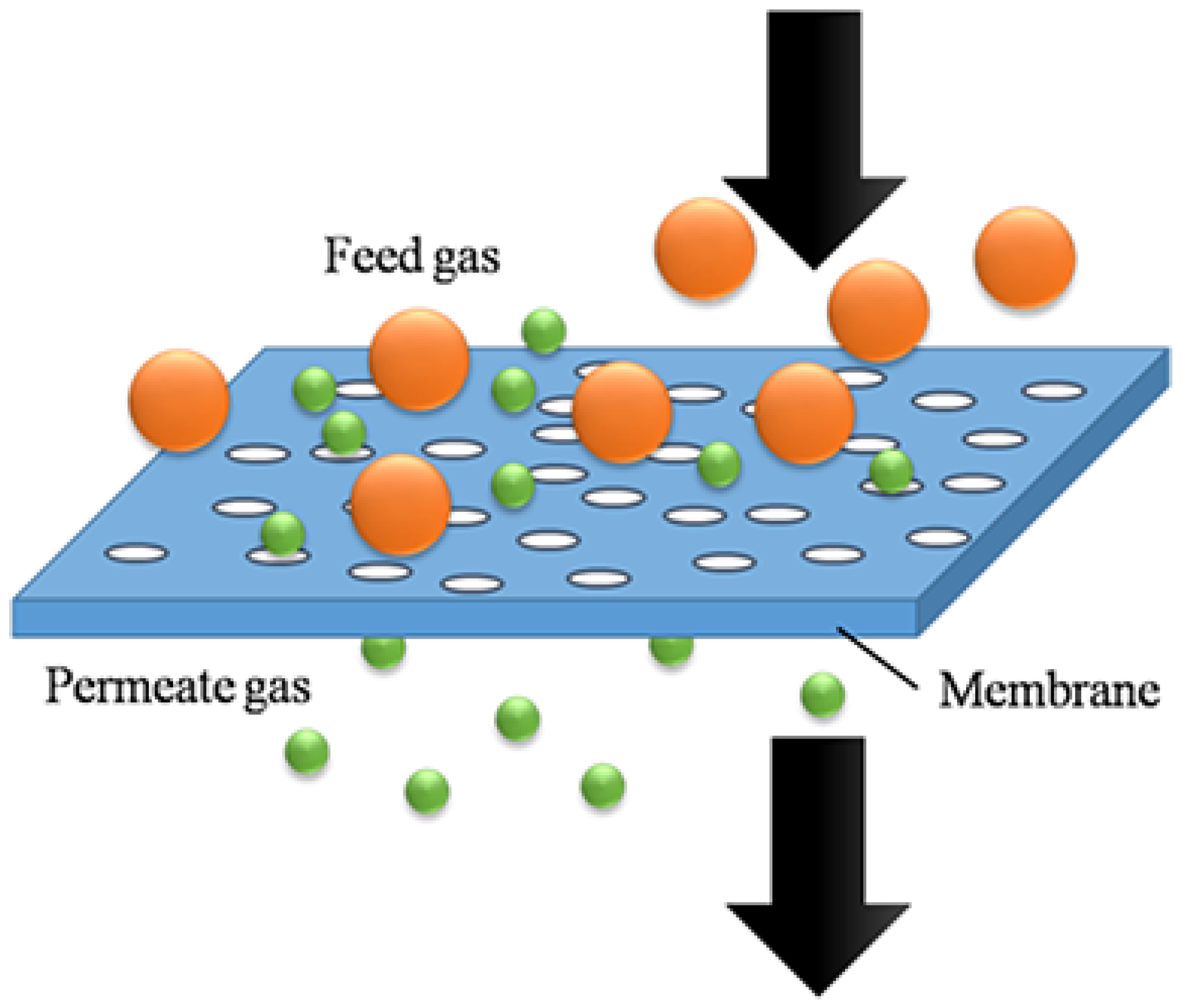
2.1.3. Membrane Separation Method

Membrane separation is an emerging method for physically separating the CO2 from flue gases through a semi-permeable membrane [42], which achieves gas separation according to the difference in the permeation rates of the various gas components on the surfaces of polymer membranes. Compared to traditional chemical absorption technology, membrane separation has a lower energy consumption, lower cost, smaller footprint, and simple process configurations [43,44].
The membranes include inorganic membranes and organic membranes. For the CO2 capture process, inorganic membranes can screen out the CO2 from mixed gas according to molecular size, whereas organic membranes selectively permeate this CO2 due to the specific interaction of the CO2 and the functional groups attached to the membrane surface. Inorganic membranes primarily include zeolite, metal organic framework, carbon molecular sieve, ceramics, and some metal oxides (alumina, titania, and zirconia) [45]. Inorganic membranes can withstand high temperatures of 400 °C or even 500 °C. In addition, they also have a high mechanical stability, but their cost is high. Organic membranes are polymer composite membranes, such as polyethylene (PE), polypropylene (PP), polytetrafluoroethylene (PTFE), and polyvinylidene fluoride (PVDF). Among them, the hollow fiber membrane in the PP membrane has been commercialized due to its cheap cost [46,47]. However, the PP membrane may degrade at temperatures from 100 to 150 °C, which is the biggest obstacle to its industrialization. Among the above four membranes, PTFE can withstand high temperatures of 150 °C, but its cost is relatively high, which is not suitable for industrialization [48].
In Figure 1, the CO2 in feed gas reaches the pores of the membrane, diffuses to the penetration side, and is finally enriched on the penetration side [49]. For membrane separation technology, the capacity of the CO2 capture is determined by the selectivity and permeability of the membrane. Koros et al. found that creating thin selective layers on permeable porous carriers can improve the selectivity and permeability of the membrane, further enhancing this CO2 capture capacity [50,51]. In addition to the selectivity and permeability of the membrane, the CO2 concentration in feed gas, the pressure difference between the feed side and permeate side, and the membrane separation method all affect the separation effect of the membrane.
The difference in the CO2 concentration on both sides of the membrane is the main driving force for membrane separation. Increasing the CO2 concentration in the feedstock makes this separation easier. Studies have shown that, when the CO2 capture rate is 90%, the energy consumption for the solvent absorption and membrane separation method is comparative when the CO2 concentration in the feed gas is 10 mol%. However, with a continuous increase in the CO2 concentration, the energy consumption for the membrane separation is much lower than that in the solvent absorption method. Therefore, the solvent absorption method is generally used for low-concentration CO2, while membrane separation is used for medium- and high-concentration CO2 [53]. In addition, the membrane separation method is also an important factor for the separation effect of the membrane. A single membrane system is generally used in the early stages of membrane separation, but when the CO2 capture rate reaches 90%, the CO2 purity is only 50%. If the CO2 purity is greater than 90%, the selectivity of the membrane needs to be at least greater than 200, which can result in high capital and operating costs [54]. Furthermore, in Table 2, it can be seen that, when the CO2 capture rate is 90%, if the CO2 purity increases from 95% to 98%, the capture cost significantly increases. Therefore, the CO2 purity required by the subsequent process has a significant influence on the cost of the membrane separation.

2.1.4. Pressure Swing Adsorption

Among the carbon capture methods, the absorption method is currently the most mature. However, the absorption method inevitably has problems such as a high energy consumption and the corrosion of its process equipment. Therefore, the adsorption method, represented by pressure swing adsorption (PSA), is developed [55]. PSA technology generally uses adsorbents with microporous or mesoporous structures as a fixed bed [56]. Table 2 shows some common adsorbents and some specific parameters, advantages, and disadvantages of PSA. Herein, the common adsorbents mainly include zeolite 13X and zeolite NaY, in which zeolite 13X has a relatively strong CO2 adsorption capacity.
The ultimate goal of PSA technology now is to capture CO2 with minimal energy consumption. Based on a traditional PSA design, Ammar et al. used a compact plate to transfer the heat generated during the CO2 capture process to the desorption process, ensuring a more effective heat dissipation from the adsorption bed and reducing the energy required for the regeneration steps [57]. However, in the PSA process, the partial pressure of the CO2 desorption is close to the ambient pressure and the absorption pressure can reach at least 7 bar, which means that the feedstock needs to be compressed, causing additional energy consumption [58]. Subsequently, researchers have developed vacuum swing adsorption (VSA) to solve this problem. VSA was industrialized in 1986 and is considered to be the most likely alternative to PSA, due to its low energy consumption and the long life of its adsorbent. In the VSA process, the partial pressure of the CO2 in the feed gas is generally lower than 1.5 atm [59] and the desorption pressure is lower than 10 kPa [60]. Regardless of VSA and PSA, even if the 13X adsorbent with the best adsorption performance is chosen, the single-stage process has a recovery rate of 90% and the CO2 purity is only 76% [61]. Therefore, it would be better to choose a two-stage process. The first stage is mainly to obtain a higher CO2 capture rate and the second stage is to increase the CO2 purity, so that the final CO2 capture rate can reach 90% and the CO2 purity is 95% [62]. Yu et al. used a two-stage VSA method to capture the CO2 from flue gas. This process combined dynamic and equilibrium control separation processes with reflux. The first stage was dynamic control separation, which removed most of the N2 from the dry flue gas, increasing the CO2 concentration by 54.1%. This stage greatly reduced the subsequent treatment volume. The second stage adopted balance control separation and the final CO2 purity was 95.1%, with a recovery rate of 92.9% [63].
At present, there are two critical problems in PSA or VSA. First of all, although the process configuration of PSA is simple, the area of its fixed bed reactor is much larger than that in solvent absorption and membrane separation [62]. Researchers are currently studying the feasibility of moving bed reactors in PSA [64]. In addition, the steam in flue gas has a negative effect on the CO2 adsorption. On the one hand, many adsorbents are hydrophilic, such as 13X zeolite. On the other hand, flue gas generally contains 8% to 10% steam, and even after pretreatment, its steam concentration can reach up to 5% [65]. Steam and CO2 can form competitive adsorption on the adsorbent, reducing the adsorption capacity of the adsorbent for the CO2 [66]. There are two methods to solve this problem. The first option is to use hydrophobic adsorbents, such as MOF and amine functional adsorbents [62]. The second option is to use two fixed beds. The adsorbent of the first fixed bed uses Al2O3 or silica gel to absorb the steam and the adsorbent of the second fixed bed uses zeolite 13X to absorb the CO2 [67].
Table 2. Comparison of four CO2 capture methods [45,53,60,61,68,69,70,71,72].
Capture MethodChemical Absorption MethodPhysical Absorption MethodMembrane Separation MethodPressure Swing Adsorption Method
Absorbent/AdsorbentMEA/MDEAMethanolInorganic/organic membraneZeolite/molecular sieve/activated carbon/alumina/MOF
Inlet CO2 concentration<20%>20%>28%20–60%
Outlet CO2 concentration≥99≥95≥99.9Single-stage: 76
Multiple-stage: >95
Capture rate90%90%90%90%
Technology maturityHighHighPilot stageHigh
Processing capacityHighHighLowMedium
Operational difficultyLowLowHighMedium
Cost ($/t CO2)50–6540–6023–4732–34
Advantages
  • Mature technology.
  • Mature technology.
  • Low energy consumption.
  • Low energy consumption.
2.
High CO2 purity.
2.
High CO2 purity.
2.
High mass transfer efficiency.
2.
Low operating costs.
3.
Large processing capacity.
3.
Large processing capacity.
3.
Low operating costs.
3.
Simple process.
Disadvantages
  • High regeneration energy consumption.
  • High regeneration energy consumption.
  • Relatively immature technology.
  • H2O has a negative effect on the adsorbent.
2.
Low absorption rate.
2.
Amine solutions degrade easily.
2.
Relatively high fixed cost of inorganic membrane.
2.
The PSA/VSA unit covers a relatively large area.
3.
Amine corrodes the equipment.
3.
Organic membrane is not resistant to high temperatures and will swell and age.

2.1.5. Comparison of Four CO2 Capture Methods

The solvent absorption methods (chemical absorption and physical absorption methods) are the most mature, and their CO2 purity is also the highest. However, their high solvent regeneration energy consumption cannot be ignored. Adopting an advanced solvent has been proven to be an effective method. Membrane separation and PSA methods are superior to solvent absorption methods in terms of their operating costs and energy consumption, but they are still a long way from large-scale applications. For membrane separation methods, membrane degradation and high-temperature resistance are the bottlenecks to its development. With the investment of large amounts of funds into membrane research, novel membranes may solve these issues. PSA has rigorous requirements for its feed materials. As mentioned before, the steam in the feed can form competitive adsorption with the CO2 on the adsorbent, significantly reducing the adsorption capacity of the adsorbent. In addition, maintaining the vacuum conditions of the desorption process can consume more energy, but the energy consumed is far lower than that in the solvent absorption method.

2.2. Water Electrolysis Technologies

For PTL processes, H2 generation is a critical step. Among the promising approaches to H2 generation, water electrolysis technology, which utilizes renewable electricity to split water molecules into H2 and O2, presents enormous advantages [9]. Up until now, water electrolysis technologies have included alkaline water electrolysis (AWE), proton exchange membrane water electrolysis (PEM), solid oxide water electrolysis (SOEC), and anion exchange membrane electrolysis (AEM), according to the types of electrolyzer.

2.2.1. Alkaline Water Electrolysis

AWE technology uses an alkaline electrolyte solution (e.g., sodium hydroxide and potassium hydroxide) for electrolyzing water to H2 and O2, and the relevant reactions are shown in Table 3. The commonly used electrolytes include potassium hydroxide (KOH) aqueous solution, sodium hydroxide (NaOH) aqueous solution, and ionic liquids. The KOH aqueous solution is a strong alkali, with a concentration typically between 25 and 30 wt% [73,74]. Under the same concentration and volume, the KOH aqueous solution can generate more H+, promoting H2 and O2 formation. Compared to the KOH solution, the NaOH solution may have significant cost advantages, but its conductivity is lower. Ionic liquids, such as electrolytes, have the advantages of a low vapor pressure, non-volatility, and a high chemical and thermal stability, but their higher viscosity and cost limit their commercialization [75]. At present, AWE technology has achieved large-scale industrial application because of its relatively mature technology, simple process, and low equipment cost. However, its electrolysis efficiency is relatively low, with values of 51–60% (based on lower heating value). Hence, improving the electrolysis efficiency is the key to the current development of AWE. The factors that affect the electrolysis efficiency mainly include the temperature and current density.
From the perspectives of kinetics and thermodynamics, as the temperature increases, the electrolyte ionizes more ions, and the movement rate of these ions accelerates. Therefore, increasing the temperature is also beneficial for improving the electrolysis efficiency. However, an increase in the temperature can lead to more energy consumption [76]. In addition to increasing the temperature, some optimizations can improve the electrolysis efficiency. For example, Lei et al. proposed acidic/alkaline amphoteric electrolysis technology. With this technology, the cathode and anode electrolytes were H2SO4 and KOH, respectively. It was found that the productivity of H2 increased by more than four times and the energy consumption decreased by 30 to 35% [77]. Zhao et al. designed an IFP electrolytic cell and tested the energy consumption and H2 purity under two operating conditions: a fused fluid flow path (FFP) and independent fluid flow path (IFP). The results showed that, after purification, the purity of the H2 reached 99.99%. In addition, due to the improvement in the separation problem, the H2 generation efficiency of the IFP electrolytic cell increased by 17.46% under the same conditions. Under the same generation of H2, the energy consumption was reduced by more than 3.29% [78].
In addition to the aforementioned issues, the risks of combustion and explosion due to the mixture of H2 and O2 are crucial for an electrolysis system. Generally, the concentration of the H2 in the O2 needs to be lower than 2% [79]. In order to solve this issue, Haug et al. studied the effects of the electrolyte concentration, electrolyte temperature, and electrolyte temperature. It was found that the average flow rate of the electrolyte decreased from 0.00768 to 0.00325 L·s−1, resulting in a decrease in the anode H2 content from 1.636 to 0.701 vol%. When the electrolyte concentration increased from 28.9 to 34.2, the H2 content at the anode decreased from 1.350 to 0.911 vol%. When the electrolyte temperature increased from 50 to 80 °C, the anode H2 content decreased from 1.348 to 1.090 vol%. Therefore, a high temperature, high alkali concentration, and low alkali flow rate can reduce the H2 content in the anode and improve the O2 purity [76].

2.2.2. Proton Exchange Membrane Electrolysis

PEM technology uses an acid electrolyte solution for splitting water into H2 and O2 using the proton exchange membrane. Different from the diaphragm used in AWE technology, the proton exchange membrane only allows for H+ to pass through, separating H+ and O2−. At the same time, it can also transfer H+ protons and serve as a carrier for anode and cathode catalysts [80]. As an essential module, the PEM cell mainly includes two bipolar plates, a proton exchange membrane, and two gas diffusion layers (GDL). Bipolar plates are usually nickel-plated and are primarily used as a flow channel to ensure a uniform and stable water flow. They are connected in series to the circuit to establish a complete current path between the cathode and anode. The GDLs generally use porous materials to transport the H2O, H2, and O2.
As the core component of the water electrolysis cell electrode, the proton exchange membrane directly determines the performance and service life of the water electrolysis cell, so it is crucial within the entire equipment. At present, the industrialized application of the proton exchange membrane is the perfluorinated sulfonic acid (PFSA)-type proton exchange membrane (Nafion membrane), developed by DuPont in the 1960s. It has the advantages of a high proton conductivity, strong chemical stability, and high mechanical strength [81]. PEM technology has the advantages of a compact structure, high current density, fast response speed, and small footprint, which is moving it from development to industrialization, with its commercialization becoming increasingly mature. However, there are still problems, such as a low electrolysis efficiency and membrane degradation. Typically, operating temperature, film thickness, and current density can significantly affect the electrolysis efficiency. More specifically, the effect of the operating temperature on PEM is similar to that in AWE technology. Increasing the temperature can improve the electrolysis efficiency. For example, López et al. found that, at higher temperatures and lower pressures, the efficiency of the electrolytic cell can reach its maximum and better adapt to power fluctuations [82]. The thickness of the membrane has a significant impact on the electrolysis efficiency. A decrease in the membrane thickness leads to an increase in the electrolysis efficiency. For example, Toghyani et al. found that the current density could increase by more than 48% and the electrolysis efficiency could increase significantly if the thickness was reduced from 200 to 50 mm under a working voltage of 1.6 V. However, the reverse diffusion of the H2 to the anode also increased, which is unfavorable. The effect of the current density on the electrolysis efficiency is the most significant among all of the influencing factors. The contribution rate of the anode current density to the electrolysis efficiency can be as high as 67.5%. By increasing the anode current density, the electrolysis efficiency of PEM can be significantly improved [83]. However, with an increase in the current density, the permeability of the H2 to the anode increases. If the volume fraction of the H2 in the O2 exceeds 2%, some security issues, such as explosions, may occur.
Membrane degradation is an unavoidable problem in PEM, which mainly occurs on the cathode side. The mechanism of membrane degradation is quite complicated. Firstly, O2 is attached to the anode. Under the action of the catalyst, H2O2 is easily generated through the two-electron reaction. The hydroxyl (HO) and hydroperoxy (HOO) produced by the H2O2 decomposition can attack the chemical structure of the membrane with different steps, releasing hydrofluoric acid (HF). Therefore, the fluorine emission rate (FER) is a critical elevation indicator of the membrane stability [84,85]. Due to the long experimental period and high membrane degradation cost, the detailed mechanism of membrane degradation is still under continuous research [86].

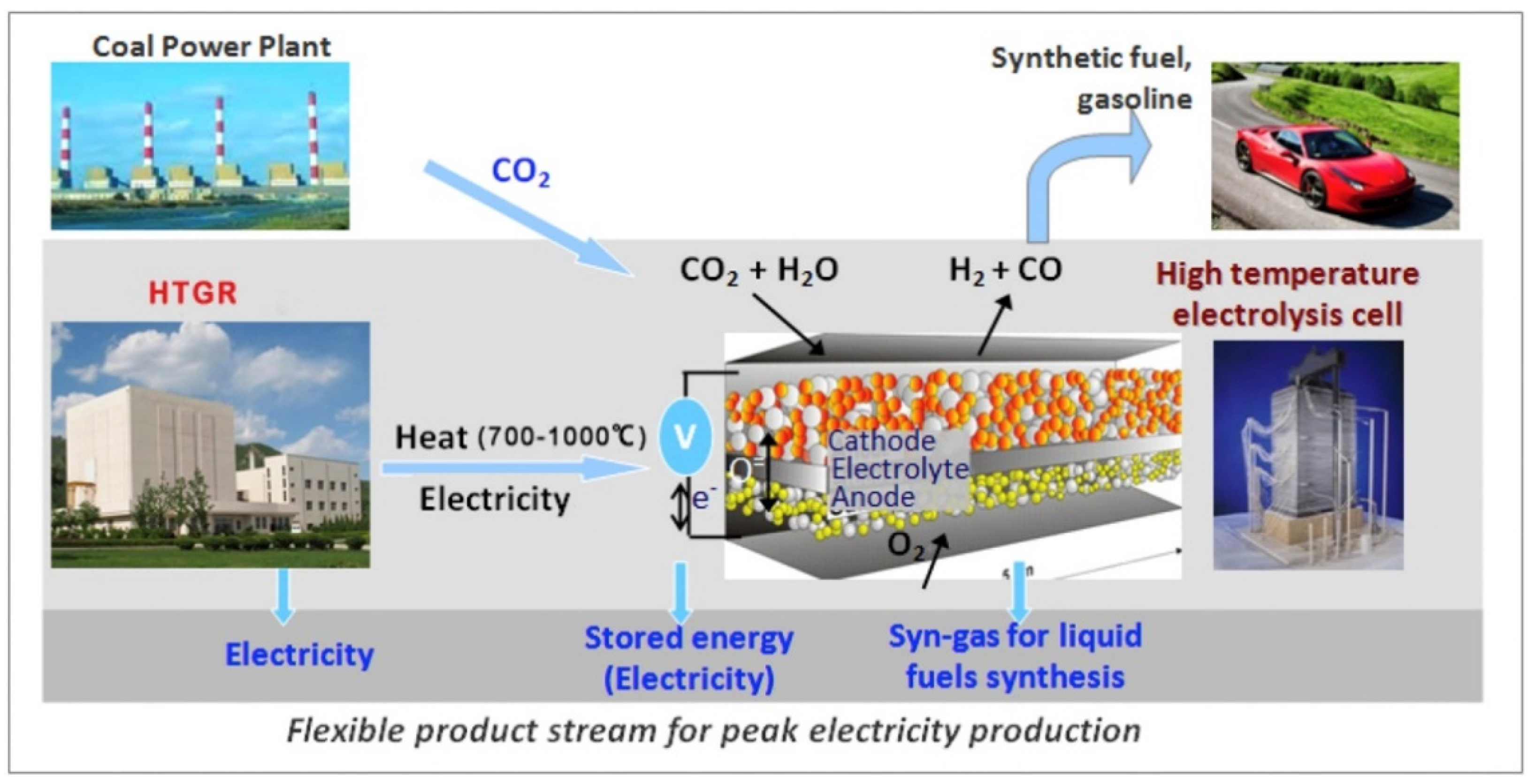
2.2.3. Solid Oxide Water Electrolysis

SOEC technology utilizes solid oxide as an electrolyte to decompose water into H2 and O2 at high temperatures. Unlike AWE and PEM technologies, SOEC technology can generally be carried out at temperatures above 800 °C. At high temperatures, water molecules are decomposed into H+ and O2−, which are then separated through a solid oxide electrolyte membrane, transferring the H+ and O2− to the anode and cathode, respectively, ultimately obtaining pure H2 and O2.
It is essential to choose the suitable electrolytes for SOEC technology. Researchers have developed various ionic electrolytes, such as yttria-stabilized zirconia (YSZ), zirconia-based, and LaGaO3-based ionic electrolytes with a perovskite crystal structure. It is worth noting that, when the electrolysis temperature exceeds 700 °C, YSZ has a better stability and lower cost than other electrolytes [87]. The cathode material is generally Ni/YSZ, which has a higher catalytic activity and lower cost than other materials [88]. The anode generally uses LSM (La0.6Sr0.4MnO3)-YSZ or LSF (La0.8Sr0.2FeO3)-YSZ, but LSF-YSZ has a better catalytic performance [89]. In addition, Table 3 summarizes the performance parameters involved in SOEC technology.
Compared to other water electrolysis technologies, SOEC technology has the advantages of a high electrolysis efficiency. This is mainly because its high operating temperature further promotes an electrolytic reaction in the thermodynamics and kinetics in comparison to low-temperature electrolysis. In addition, it also has the advantages of flexible operating modes and a wide fuel adaptability. In the future, SOEC is expected to become an important technology for connecting the development of multi-energy systems. However, expensive electrolytic cells and its high energy consumption are still the main obstacles to its industrialization.
Syngas, a raw material for producing basic chemicals, has played a crucial role in the industry. Currently, syngas is generally obtained through SMR and RWGS, as shown Equation (8). These processes have a high energy consumption and complicated subsequent purification steps. Recently, H2O and CO2 co-electrolysis technology based on SOEC has gained wide attention and been recognized as an important alternative pathway, as shown in Equation (9). Compared to traditional CO2 dry electrolysis, co-electrolysis technology dramatically improves the conversion of CO2 into CO due to the promoting effect of H2 and overcomes the soot deposition suffered in CO2 dry electrolysis [90]. The schematic diagram is presented in Figure 2. There is no doubt that H2O obtains electrons at the cathode, obtaining H2 and O2−. The principle of CO2 electrolysis can be divided into two types, according to the electrode material. If the cathode is Ni/YSZ, CO may be obtained through RWGS [91]. On the contrary, Yue and Irvine et al. found that CO2 may obtain electrons, generating CO via investigating the co-electrolysis based on an LSCM/GDC cathode [92]. Compared to high-temperature steam electrolysis and CO2 dry electrolysis, H2O and CO2 co-electrolysis exhibits a more complex reaction mechanism in the whole system, but has significant merits. For instance, co-electrolysis can generate rich syngas directly, simplify the process configuration, and remarkably reduce the electricity energy requirements [93].
In addition, the electrolysis temperature in SOEC technology is at least 800 °C, which results in more energy consumption and higher operating costs compared to other water electrolysis technologies. However, if the electrolysis temperature is lowered to between 300 and 400 °C, the ability of YSZ to transfer O2− is significantly reduced. How to balance the electrolysis temperature and ion conductivity of YSZ is the key to reducing the SOEC electrolysis temperature in the future [93].
RWGS reaction:
CO 2 g + H 2 g   CO g + H 2 O g                     Δ r H m θ = 42.1   kJ / mol
The co-electrolysis of CO2 and H2O:
C O 2 g + 2 H 2 O g electricity   CO g + 2 H 2 g + 3 2 O 2 g           Δ r H m θ = 525.1   kJ · mol 1

2.2.4. Anion Exchange Membrane Electrolysis

AEM is a key component of H2 generation equipment and a typical organic cationic polymer, composed of cations on the polymer skeleton and its covalent attachment skeleton. Since Leng et al. first proposed the AEM concept in 2012 [95], many researchers have been devoted to the development of AEM. The principle of AEM is the same as that of AWE. AEM technology has shown a strong competitiveness due to the application of non-noble catalysts compared to PEM and AWE technologies, and become an alternative technology to replace PEM and AWE technologies in the future. However, some key technical challenges need to be further explored and solved, such as strong alkaline-resistant membrane materials.
Since AEM electrolysis is still in the early stage of research, there are few reports on the electrolysis performance of AEM. Table 3 summarizes some of the performance parameters of AEM. The current study mainly focuses on the development of catalyst materials and anion exchange membranes. Choosing the appropriate non-precious metal catalyst can directly affect the investment cost of AEM electrolysis. According to the literature, catalysts such as graphene, Ni-Fe alloys, and Cu0.7CO2.3O4 have been used as anode catalysts, and catalysts such as CuCoOx and Ni-Mo have been used as cathode catalysts [96]. With the further development of these catalysts, the problem may be solved. In addition, the anion exchange membrane has a lower chemical stability under alkaline conditions, which seriously hampers the industrial application of AEM. The main reason for this is that hydroxide easily breaks the main chain of the polymer in an alkaline environment, reducing the mechanical strength and conductivity of the membrane. At present, commercial membranes, such as PEEK, PESU, and PPO, have this problem. Therefore, many researchers are devoted to studying the mechanism of membrane degradation in order to solve this problem fundamentally [97,98].

2.2.5. Comparison of Four Electrolysis Technologies

SMR technology is the most widely used in industry, but its by-products may generate a large amount of CO2, aggravating global warming [99]. It is necessary to develop alternative technologies to produce green H2. Water electrolysis technology with close to zero CO2 emissions may be the best solution to this problem. In the above four water electrolysis technologies, AWE has been identified as the most likely technology for large-scale industrial realization [100]. However, as shown in Table 3, AWE also has a relatively low electrolysis efficiency compared to other technologies. Moreover, the AWE cell response time is longer, which means that, when the input renewable energy fluctuates, the AWE cell cannot respond in time, which may cause cell damage. PEM technology, which has the advantages of a high electrolysis efficiency, high operating pressure, convenient maintenance, and fast response, is attracting more and more attention. However, as shown in Table 3, it can be seen that PEM needs precious metal catalysts, which significantly increases the cost of PEM cells. According to the literature, the cost of a PEM catalyst is about 70 $/kW at present. With the continuous development of PEM electrolysis technology, the catalyst cost may be reduced to 18 $/kW, which is acceptable to a certain extent. In addition, proton exchange membranes, such as PFSA, may release environmentally harmful HF during the recovery process [97,101]. SOEC has the highest electrolysis efficiency out of the four electrolysis technologies, but its high-temperature operation consumes much energy, hindering its large-scale commercialization.
We consulted with many pieces of research and found that most researchers only compared three other technologies except AEM. This was mainly because AEM is still in the theoretical development stage and lacks technical and economic parameters. Table 3 summarizes the technical parameters related to AEM that can be found in the existing literature. It can be found that AEM has significant advantages over the other three technologies. The electrolyte of AEM uses a 1 wt% K2CO3 solution. The electrolyte also chooses distilled water, ultrapure water, and a 0.1 mol·L−1 KOH solution, which reduces the corrosion of the membrane by the strong alkaline solution [98]. AEM generally uses transition metal catalysts instead of noble metal catalysts, reducing its economic cost.
Among the four electrolysis technologies, AWE has the lowest investment cost and most mature technology, making it the most suitable solution for preparing H2 [102]. PEM electrolysis costs are relatively high, but it is possible for them to be reduced to 500 EUR/kW by 2050 [103]. SOEC has the highest investment cost among them due to its high operating temperature. However, Hauch et al. estimated that, with the rapid development of SOEC technology, its cost could be reduced to 530 EUR/kW by 2050 [104]. The AEM economy has not been reported in the literature. The current four electrolysis technologies are not economically comparable with SMR. However, with the large-scale use of renewable energy, lower electricity prices, higher carbon taxes, and government financial support, the four electrolysis technologies may replace SMR.
Table 3. Comparison of four electrolysis technologies [79,80,98,105,106,107,108,109].
AWEPEMSOECAEM
Operation conditions
Charge carrierOHH+O2−OH
Cathode materialsNiNiNi-YSZNi-Fe-Co
or NiMo-NH3/H2
Cathode catalystPtPt, Ir, RuNiCeO2-La2O3
Anode materialsNiNi or CLSM-YSZ or LSF-YSZNi-Fe-Ox
or Fe-NiMo-NH3/H2
Anode catalystPtPtLSM-YSZ or LSF-YSZCo3O4
ElectrolyteKOHH2SO4YSZ1 wt% K2CO3
Isolation mediumPPS/PES aPFSA bN.A.QAPS c
Operation parameters
Pressure of work (bar)10–3020–501–1530
Electrolytic temperature (°C)60–8050–80700–90050–80
Current density (A/cm2)0.25–0.451–20.3–1.00.2–0.5
Flexibility
Start-up time5 min<10 s15 minN.A.
Efficiency
Commercial system electrolysis efficiency (LHV)51–6060–6576–8164
Specific energy consumption (kWh/Nm3)5.0–5.94.6–5.03.7–3.94.7
H2 purity (vol%)99.599.9999.999.99
Durability
Life time (kh)55–12060–1008–20N.A.
Economic parameters
Investment cost (EUR/kW)800–15001400–2100>2000N.A.
Maintenance costs
(% of annual investment cost)
2–33–5N.A.N.A.
Anode reaction4OH → 2H2O + O2 + 4e2H2O → 4H+ + O2 + 4eH2O + 2e → H2 + O2−4OH → O2 + 2H2O + 4e
Cathodic reaction4H2O + 4e → 2H2 + 4OH2H+ + 2e → H22O2− → 4e + O24H2O + 4e → 2H2 + 4OH
Total reaction2H2O → 2H2 + O2
a Polyphenylene-sulfide membrane (PPS) and polyether sulfone membrane (PES) are composite materials based on ceramic materials and microporous materials, which can be used as the diaphragm between the cathode and anode of AWE. b Perfluorosulfonic-acid (PFSA) proton exchange membrane represented by DuPont’s Nafion® membrane. c A quaternary ammonium polysulfone membrane represented by the A-201® membrane of Tokuyama Corporation of Tokyo, Japan.

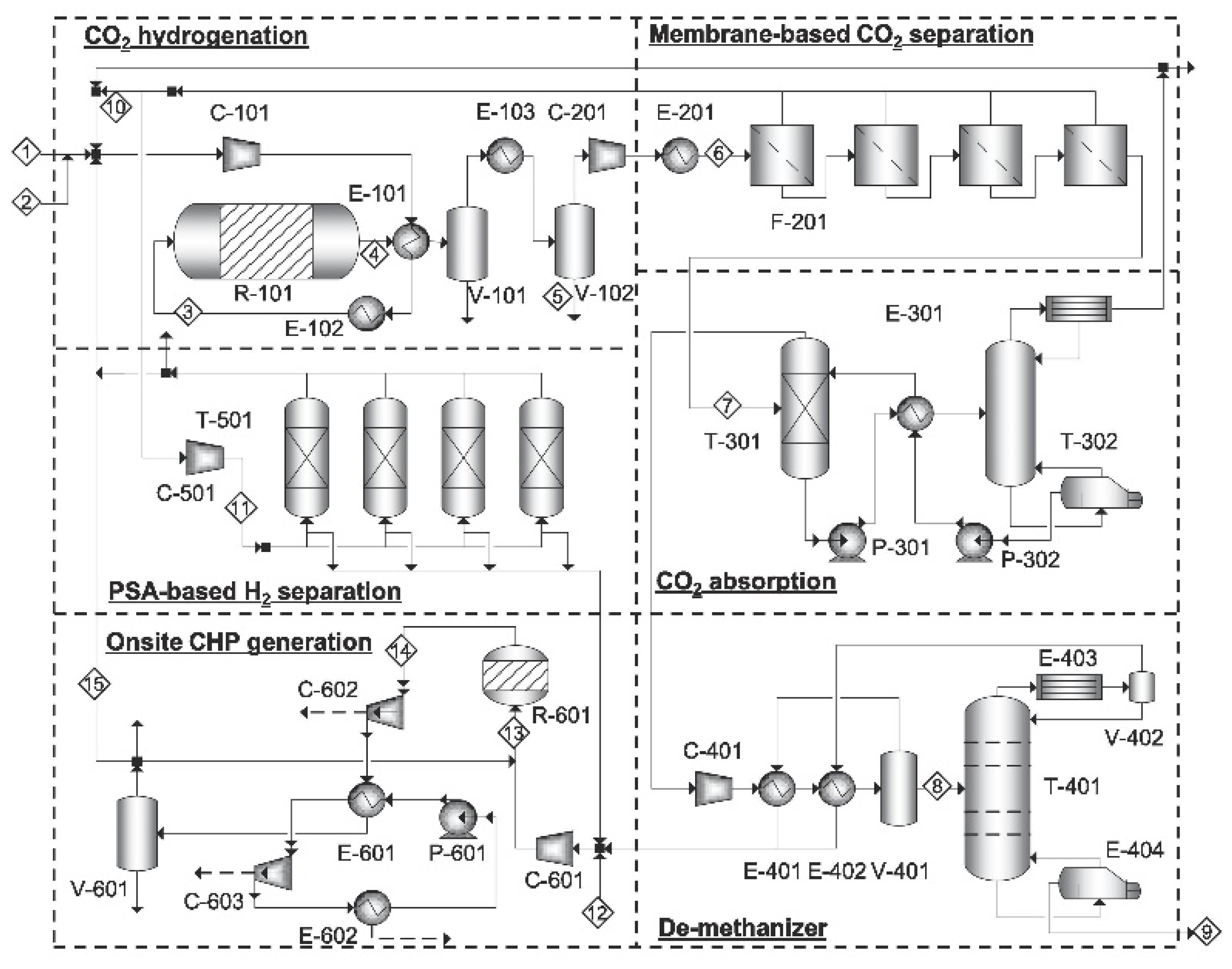
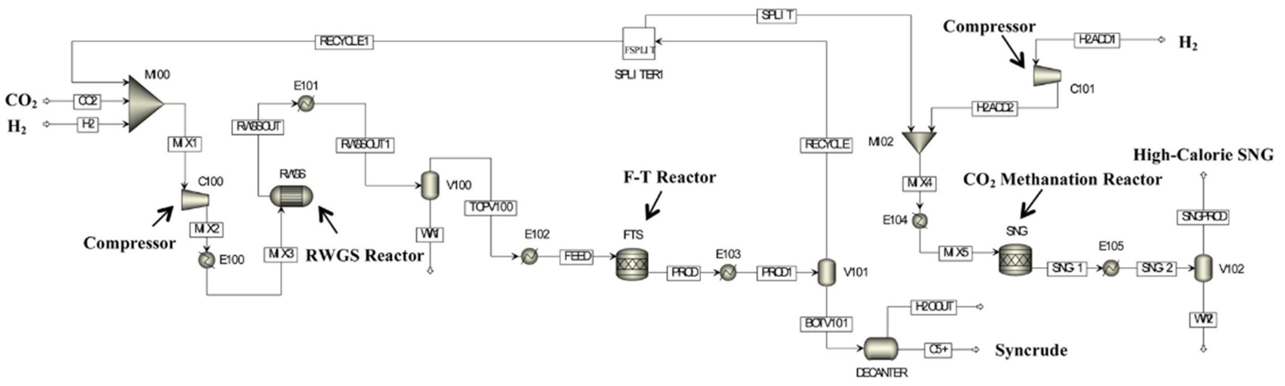
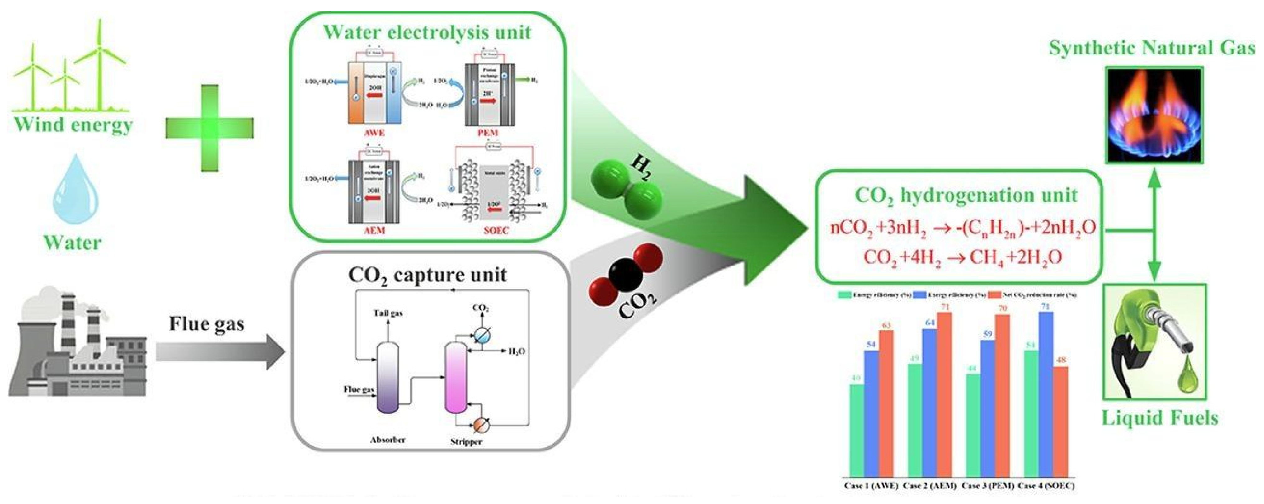
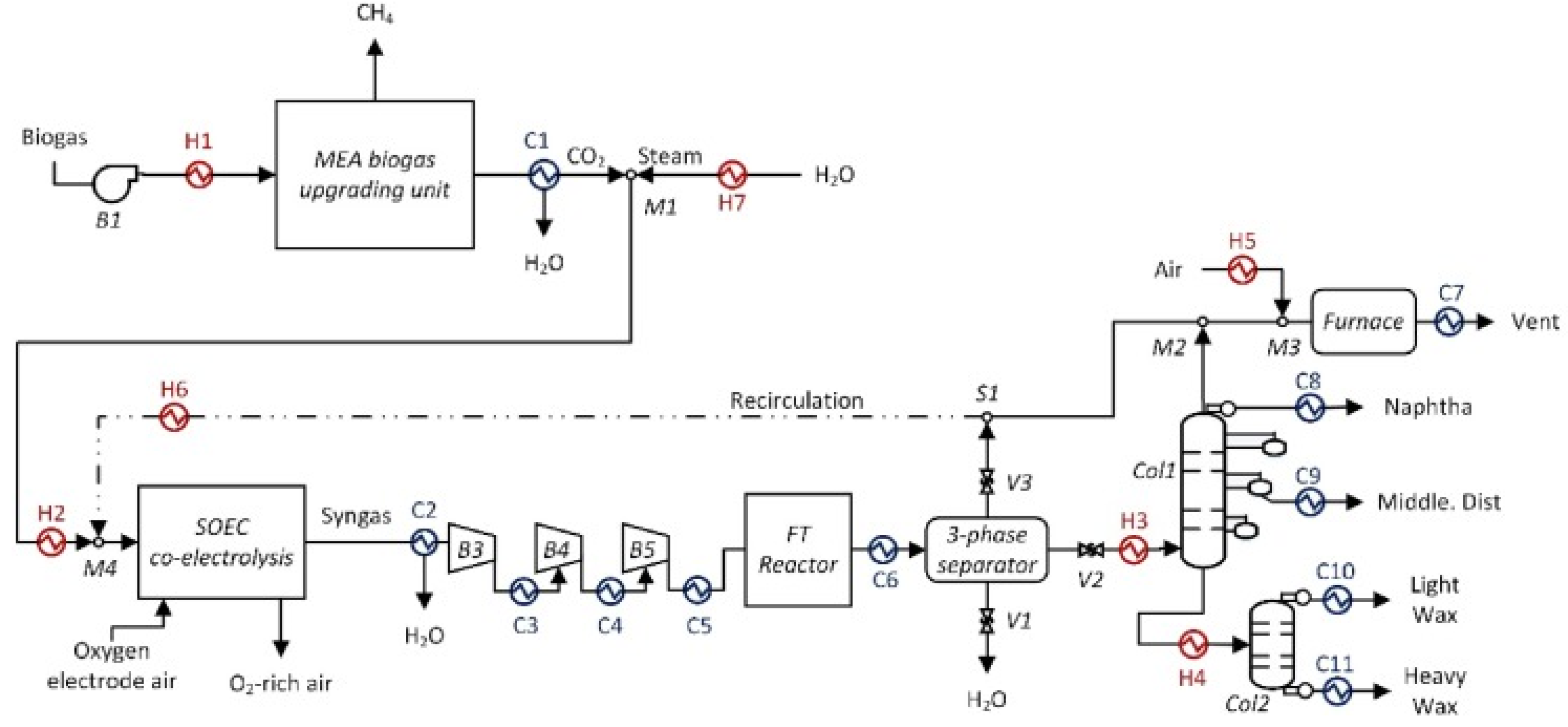
2.3. CO2 Hydrogenation to Liquid Fuels Technologies

At present, CO2 and H2 can be converted into hydrocarbons via the methanol-mediated and modified FT-based pathways. As highlighted above, this work mainly focuses on the modified FT-based pathway, due to its simple process configuration and adjustable product selectivity. Generally, modified FT-based pathways are mainly divided into high-temperature Fischer–Tropsch synthesis (HTFT) and low-temperature Fischer–Tropsch synthesis (LTFT) processes [110]. Generally, the targeted syncrude obtained via HTFT and LTFT can be further purified and upgraded to liquid fuels, including gasoline (C5–C12), naphtha (C5–C12), and diesel (C12–C20) [111]. The differences between the HTFT and LTFT processes mainly lie in their operating conditions and catalysts. For the HTFT process, its operating temperature is about 300~330 °C. CO2 and H2 are converted into C1–C4 paraffins, C2–C4 olefins, and C5+ hydrocarbons over Fe-based catalysts. In addition, HTFT products may contain oxygen-containing compounds and aromatic compounds, but almost no residues, such as paraffin wax [112,113]. For the LTFT process, its operating temperature is about 200~280 °C and CO2 is hydrogenated over Co-based catalysts. Herein, Co-based catalysts are suitable for synthesizing straight-chain alkanes in a range of liquid waxes, especially for C5+ hydrocarbons with a high selectivity [10,114]. It is worth noting that a Co-based catalyst has no catalytic activity for CO2, so it is necessary to convert CO2 into CO, which can be achieved via the RWGS reaction [115]. In addition, Co-based catalysts are prone to methanation at high temperatures [116]. By adding K to Co-based catalysts, the methanation reaction can be effectively suppressed and the selectivity of the C5+ hydrocarbons can be increased [117].
For HTFT and LTFT processes, the reaction temperature, superficial gas velocity, particle diameter, and bed height affect the composition of the product. Among the various factors, the influence of the reaction temperature is the most significant. Given that the endothermic RWGS reaction generally competes with the exothermic FT synthesis reaction, an increase in the reaction temperature can accelerate the reaction rate, whereas the yield and the selectivity of the C5+ hydrocarbons start to decrease. This is mainly because an increase in the operating temperature promotes the RWGS reaction, resulting in a higher CO selectivity [118]. Moreover, considering that both the HTFT and LTFT reactions are strictly limited by the thermodynamic equilibrium, therefore, there are considerable amounts of unreacted CO2 and CO in the unreacted syngas derived from the outlet of the FT syntheses reactor, which can be recycled to the previous FT synthesis reactor in order to improve the production of the syncrude. Generally, the CO2/CO ratio in the recycled unreacted syngas could affect the process performances. With this in mind, Jun et al. investigated the effects of the CO/CO2 ratio in unreacted syngas on the catalytic behavior in an FT synthesis reaction over K/Fe-Cu-Al catalysts. The results indicated that a high CO2/CO ratio is beneficial for efficient CO2 conversion and prevents carbon disposition, providing good guidance for the subsequent process design [119].
As mentioned above, the CO2 conversion in HTFT and LTFT reactions is relatively low. Therefore, considerable efforts have been devoted toward the development of strategies for promoting the transformation of CO2 into high value-added hydrocarbons, such as water removal and multiple FT synthesis reactors in series. More specifically, water is one of the primary byproducts of the FT synthesis reaction and its accumulation can significantly reduce the driving force of the reaction, easily resulting in catalyst deactivation [120]. To address these issues, Hyeon et al. removed the water in situ by using a thermally rearranged polybenzoxazole membrane (See Figure 3), and found that the selectivity of the targeted low-carbon olefins was improved by 2~6% [121]. The aforementioned membrane reactors are still in their research and development stage and have a long way to go before their large-scale deployment. With regard to multiple FT synthesis reactors in series, these have become the research emphasis in industry and academia. Meiri et al. adopted three reactors in series with condensation devices in order to convert CO2 into targeted low-carbon olefins. The results indicated that the CO2 conversion was significantly increased by more than 20% [122]. Kamkeng et al. proposed two improved FT process configurations (including a three-stage reactor in series and a single reactor with recycling) to facilitate off-site water removal (See Figure 4). They found that the application of three reactors in series notably improved the CO2 conversion by 36% and the gasoline production by 27% [123].
For HTFT and LTFT synthesis reactions, the obtained crude products also include light hydrocarbons (i.e., C1–C4 paraffins and C2–C4 olefins), which are generally considered to be inert components during the recycling process [124]. Therefore, achieving an efficient utilization of these light hydrocarbons has become the emphasis. In traditional HTLT and LTFT processes, light hydrocarbons can be converted into CO and H2 via high-temperature reforming technology, which are then recycled into the FT synthesis reactor, together with the unreacted syngas. However, this energy-intensive reforming process inevitably generates considerable carbon emissions. Hence, it is necessary to develop more clean and sustainable processes. Recently, some emerging processes have been proposed to further achieve the upcycling of these light hydrocarbons. In light hydrocarbons, C2–C4 hydrocarbons are important platform chemicals for the petrochemical industries [125]. Therefore, in the work of Kim et al., methane was separated from light hydrocarbons, using the distillation method to obtain high value-added C2–C4 hydrocarbons (See Figure 5). Therein, the methane was sent to the combined heat and power unit to generate utilities on site [126]. Mahouri et al. also conducted similar work. They sent light hydrocarbons to the energy recovery unit to generate sufficient steam or electricity for internal use [114]. Adelung et al. considered light hydrocarbons as fuel and sent them to the burner to obtain high-temperature steam, which could be used to preheat the energy-intensive RWGS reactor and other heaters, further reducing the external utility consumption [127]. Moreover, emerging co-electrolysis technology has been proposed. For example, Cinti et al. proposed an efficient CO2 hydrogenation to liquid fuel process, coupled with SOEC water electrolysis technology. Therein, light hydrocarbons were recycled into the previous high-temperature SOEC cell to obtain syngas [128]. In addition to the aforementioned methods, in our previous work, an integrated process coupled with HTFT and methanation technology was proposed. As shown in Figure 6, unreacted syngas and light hydrocarbons were sent to the subsequent methanation unit to produce high-caloric synthetic natural gas (SNG). The hybrid process achieved the co-production of syncrude and high-caloric SNG, further improving the carbon utilization efficiency [129,130]. Furthermore, light hydrocarbons consist of considerable light olefins, which can be further converted into high value-added C5+ hydrocarbons via an oligomerization reaction over modified HZSM-5 catalysts. In the previous work, we proposed a CO2 hydrogenation process integrating HTFT and olefin oligomerization technologies (See Figure 7). The results indicated that the application of an oligomerization reactor further enhanced the syncrude production and improved the energy efficiency [131,132].

3. Technical and Economic Analysis of PTL Processes

Technical and economic analyses (TEA) of the PTL process are crucial for the development and commercialization of these PTL processes. However, variations in regional and temporal factors, as well as fluctuations in government policies and regulations, have led to significant disparities among the different PTL processes [133]. This section addresses this gap by evaluating the existing PTL processes from technical and economic perspectives.

3.1. Technical Analysis of PTL Processes

Numerous researchers have dedicated significant efforts to enhancing the liquid fuel production and process efficiency. Furthermore, adopting efficient water electrolysis has been proven to be crucial for improving the technical performances of the emerging PTL processes.
Generally, the stack efficiency and operating conditions of the electrolyzer in water electrolysis technologies have significant effects on the technical performances of the PTL process.
Herz et al. suggested a PTL process with SOEC technology; meanwhile, advanced heat integration and byproduct recirculation methods were applied to further the energy-saving potential of the system. The results revealed that the overall process efficiency was improved by more than 7% [134]. Markowitsch et al. evaluated the technical performances of PTL processes configured with PEM and SOEC technologies. It was concluded that the application of SOEC technology with a higher stack efficiency had a higher PTL efficiency, improving it by 10% [135]. Moreover, considering the lack of comprehensive comparisons of the effects of different water electrolysis technologies (i.e., AWE, AEM, PEM, and SOEC) on the technical performances of PTL processes, we proposed four hybrid PTL/PTG processes coupled with different water electrolysis technologies (See Figure 8) and compared their process performances in terms of their carbon efficiency, energy efficiency, net CO2 reduction rate, and exergy efficiency. It was found that the hybrid PTL/PTG process coupled with SOEC technology had the highest energy (54.26%) and exergy efficiencies (70.74%), due to having the highest stack efficiency. However, the hybrid PTL/PTG process coupled with AEM technology had the highest carbon efficiency (75.04%) and net CO2 reduction rate (70.58%), due to its relatively mild operating conditions [8]. In addition to the aforementioned water electrolysis technologies, co-electrolysis technology has shown a strong application potential in PTL processes [128,136]. In the work of Marchese et al., they used a co-electrolysis device instead of an electrolyzer and RWGS reactor to generate syngas with a suitable ratio of H2 to CO (See Figure 9). The technical analysis indicated that the plant efficiency of the PTL process coupled with co-electrolysis technology had a higher plant efficiency of 81.1% compared with to the traditional PTL process [137]. Pratschner et al. proposed a similar PTL process integrated with co-electrolysis technology (See Figure 10). However, it should be noted that the CO2 was mainly derived from the flue gas in the cement plant, biogas-upgrading plant, and biomass CHP plant. The PTL efficiencies were found to be 54.7~63.8% and the carbon efficiencies were found to be 66.4~88.6%, which was mainly dependent on the specific CO2 sources [138]. At present, a co-electrolysis system at the Dresden plant was successfully launched and put into trial operation (>500 h), which has established a reliable foundation for the subsequent smooth operation of PTL plants [139].

3.2. Economic Analysis of PTL Processes

Economic analyses are an important tool for evaluating economic feasibility and profitability. Currently, considerable efforts have been devoted to conducting detailed economic assessments of PTL processes and providing deep insights for the further application of these PTL processes.
Colelli et al. evaluated the economic performances of direct and indirect PTL processes (See Figure 11). Therein, in the direct route, CO2 was converted into hydrocarbons over Fe-based catalysts. In the indirect route, CO2 was transformed into CO, which was subsequently hydrogenated to hydrocarbons over Co-based or Fe-based catalysts. The results suggested that the product cost was 460~1435 EUR/bbl for the direct route and 752~2364 EUR/bbl for the indirect route [140]. The product costs of the direct and indirect routes are both much higher than the market prices of gasoline, diesel, and jet fuel.
Generally, the price of green H2 is the dominant factor in the product cost of PTL processes [10,126,141]. Therefore, reducing the price of green H2 in the PTL process plays a decisive role in the overall economy of the process. Zhao et al. found that PTL processes could show a strong economic competitiveness compared to traditional fossil energy when the H2 price was reduced by 40% based on the existing energy policy in China [142]. Moreover, Adelung et al. also studied the influence of the H2 price on the net production costs (NPC) of PTL processes. The results showed that, when H2 prices decreased from 7.6 to 2.3 EUR/kg, the NPC was reduced from 5.47 to 1.81/kgC5+ [143]. In fact, this H2 price is closely related to the selection of the water electrolysis technology. More specifically, in our previous work, we compared the total production costs of four PTL/PTG hybrid processes coupled with different water electrolysis technologies. It was found that the PTL/PTG hybrid process coupled with AEM technology had the lowest total production cost [144]. Meanwhile, according to the work of Adelung, adjusting the full load hours of the electrolyzer could reasonably reduce this net production cost [145]. Moreover, selling the O2 byproduct could further reduce the product cost of PTL processes. For example, Fasihi et al. conducted a detailed analysis of the economic performance of the PTL process using hybrid PV-wind electricity. The minimum selling price of the syncrude was 79~135 $/bbl when the byproduct O2 was put up for sale [146]. Adopting more advanced PTL processes is also beneficial for their economic feasibility. In our previous work, the economic performances of direct and indirect PTL/PTG hybrid processes were also evaluated. The total product cost was observed to be 202~211 $/bbl for the direct route, while the total product cost for the indirect route was determined to be 215~240 $/bbl [129,130,147]. According to the aforementioned economic results, the total product cost in our previous work was significantly lower than that in the work of Colelli et al. This may mainly be because the high-calorie SNG further improved the added value of the products. In addition to the aforementioned factors, the large-scale deployment of renewable energy, a high carbon tax, and strong government incentive policies can enhance the economic viability and stimulate the development of PTL processes.

4. Conclusions and Outlook

CCU technologies have demonstrated immense potential for converting CO2 into value-added materials, chemicals, and fuels, making a significant contribution to reducing greenhouse gas emissions and fostering a more sustainable and circular economy. Among the various CCU technologies, the concept of PTL offers a pathway for the production of sustainable liquid hydrocarbon fuels, utilizing both CO2 emissions and renewable energy sources. The PTL process consists of three sub-units: CO2 capture, H2 generation, and CO2 hydrogenation. Each sub-unit involves a range of technologies, and the selection and integration of these technologies play crucial roles in determining the performance of a hybrid PTL process. In this study, we conducted a comprehensive and authoritative review of the technologies employed in PTL processes.
Through an in-depth analysis of these sub-units, we gained valuable insights into the advancements, challenges, and potential improvements in each technology. For the CO2 capture sub-unit, several viable methods were identified, specifically solvent absorption, membrane, and PSA technologies. Each technology has its own strengths and limitations. Solvent absorption, although a mature method, faces cost challenges in solvent regeneration. Membrane separation and PSA exhibit a lower energy consumption and lower operation costs, positioning them as promising alternatives to solvent absorption. Further search and development efforts should focus on enhancing the efficiency and cost-effectiveness of these CO2 capture technologies. In the H2 generation sub-unit, AWE technology has emerged as the most mature method, albeit with a lower electrolysis efficiency. Both PEM and SOEC have demonstrated relatively higher electrolysis efficiencies, with SOEC achieving an impressive efficiency of up to 81%. While PEM and SOEC technologies are on the brink of commercialization, AEM has shown promise due to its low cost and high electrolysis efficiency. Future research should aim to overcome the current limitations and promote the practical application of AEM technology. Regarding the CO2 hydrogenation sub-unit, the F-T process stands as the most popular technology. However, it faces challenges related to its high energy consumption and low energy efficiency. To address these issues, process improvements can be implemented, such as utilizing light hydrocarbons produced as fuel and redirecting them to the burner for high-temperature steam generation, thus reducing the overall energy consumption. Additionally, exploring the integration of PTL/PTG mixed processes can improve the carbon utilization efficiency by generating natural gas from the light hydrocarbons produced.
Notwithstanding its potential benefits, the current technological level of the PTL process presents challenges in terms of its production and product costs, hindering its competitiveness against traditional fuel production. To this end, academia and industry are actively focusing on improving its energy efficiency and developing cost-effective pathways. The integration of the PTL process with SOEC technology offers a promising approach to this improvement in energy efficiency. In this regard, the heat generated during the PTL process can be utilized to produce the steam required by SOEC technology, optimizing the energy utilization and further enhancing the overall efficiency of a PTL system. Additionally, excess heat can be employed to regenerate solvents in the CO2 capture process or generate power via the Rankine cycle. These integrated strategies contribute to cost reduction and improve the competitiveness of PTL liquid fuel in the market. Moreover, the industrial application of PTL heavily depends on reducing its production costs, with the CO2 capture and H2 production being the primary cost drivers. To achieve this, various measures can be implemented, such as adopting new absorbents, membrane separation, and PSA methods for the CO2 capture, and introducing policy changes related to CO2 emissions, including carbon taxes and incentive measures. Improving electricity prices, the electrolysis efficiency, and electrolytic cell capital expenditure are critical factors for reducing the H2 production costs.
In summary, addressing the current cost challenges in PTL processes is essential for their widespread adoption in the fuel production sector. The integration of SOEC technology, alongside measures for reducing the production costs in CO2 capture and H2 production, presents a promising way forward. By continuously optimizing the process and adopting favorable policies, the PTL process holds great potential in providing a sustainable and competitive alternative to traditional fuel production, contributing to global efforts towards a more environmentally friendly and economically viable energy landscape.

Author Contributions

Conceptualization, X.L. and L.Z.; methodology, R.G.; validation, L.W. and Z.T.; formal analysis, R.G.; investigation, X.L.; resources, C.Z.; writing—original draft preparation, R.G.; writing—review and editing, C.Z.; visualization, L.Z.; supervision, C.Z.; project administration, C.Z.; funding acquisition, C.Z. All authors have read and agreed to the published version of the manuscript.

Funding

This work was supported by the “Next Generation Carbon Upcycling Project” (Project No. 2017M1A2A2043133) through the National Research Foundation (NRF) funded by the Ministry of Science and ICT, Republic of Korea. We also appreciate the Natural Science Foundation of Jiangsu Province (BK20200694, 20KJB530002, and 21KJB480014), the Jiangsu Specially Appointed Professors Program, and the open program of the State Key Laboratory of High-efficiency Utilization of Coal and Green Chemical Engineering (2021−K32).

Data Availability Statement

All the data are presented in the manuscript.

Conflicts of Interest

The authors declare no conflict of interest.

References

  1. IEA. Global Energy Review: CO2 Emissions in 2021-Global Emissions Rebound Sharply to Highest Ever Level; International Energy Agency: Paris, France, 2022. [Google Scholar]
  2. Lee, B.; Lee, H.; Lim, D.; Brigljević, B.; Cho, W.; Cho, H.-S.; Kim, C.-H.; Lim, H. Renewable methanol synthesis from renewable H2 and captured CO2: How can power-to-liquid technology be economically feasible? Appl. Energy 2020, 279, 115827. [Google Scholar] [CrossRef]
  3. Pires, J.C.M.; Martins, F.G.; Alvim-Ferraz, M.C.M.; Simões, M. Recent developments on carbon capture and storage: An overview. Chem. Eng. Res. Des. 2011, 89, 1446–1460. [Google Scholar] [CrossRef]
  4. Feng, C.; Lin, T.; Zhu, R.; Wei, G.; Dong, K. Key technologies for CO2 capture and recycling after combustion: CO2 enrichment in oxygen enriched combustion of converter gas. J. Clean. Prod. 2022, 380, 135128. [Google Scholar] [CrossRef]
  5. Chowdhury, S.; Parshetti, G.K.; Balasubramanian, R. Post-combustion CO2 capture using mesoporous TiO2/graphene oxide nanocomposites. Chem. Eng. J. 2015, 263, 374–384. [Google Scholar] [CrossRef]
  6. Aziz, M.; Darmawan, A.; Juangsa, F.B. Hydrogen production from biomasses and wastes: A technological review. Int. J. Hydrog. Energy 2021, 46, 33756–33781. [Google Scholar] [CrossRef]
  7. Velazquez Abad, A.; Dodds, P.E. Green hydrogen characterisation initiatives: Definitions, standards, guarantees of origin, and challenges. Energy Policy 2020, 138, 111300. [Google Scholar] [CrossRef]
  8. Gao, R.; Zhang, L.; Wang, L.; Zhang, X.; Zhang, C.; Jun, K.-W.; Ki Kim, S.; Park, H.-G.; Gao, Y.; Zhu, Y.; et al. A comparative study on hybrid power-to-liquids/power-to-gas processes coupled with different water electrolysis technologies. Energy Convers. Manag. 2022, 263, 115671. [Google Scholar] [CrossRef]
  9. Lee, B.; Heo, J.; Kim, S.; Sung, C.; Moon, C.; Moon, S.; Lim, H. Economic feasibility studies of high pressure PEM water electrolysis for distributed H2 refueling stations. Energy Convers. Manag. 2018, 162, 139–144. [Google Scholar] [CrossRef]
  10. Dieterich, V.; Buttler, A.; Hanel, A.; Spliethoff, H.; Fendt, S. Power-to-liquid via synthesis of methanol, DME or Fischer-Tropsch-fuels: A review. Energy Environ. Sci. 2020, 13, 3207–3252. [Google Scholar] [CrossRef]
  11. Saeidi, S.; Najari, S.; Hessel, V.; Wilson, K.; Keil, F.J.; Concepción, P.; Suib, S.L.; Rodrigues, A.E. Recent advances in CO2 hydrogenation to value-added products—Current challenges and future directions. Prog. Energy Combust. Sci. 2021, 85, 100905. [Google Scholar] [CrossRef]
  12. Jiang, Y.; Wang, K.; Wang, Y.; Liu, Z.; Gao, X.; Zhang, J.; Ma, Q.; Fan, S.; Zhao, T.-S.; Yao, M. Recent advances in thermocatalytic hydrogenation of carbon dioxide to light olefins and liquid fuels via modified Fischer-Tropsch pathway. J. CO2 Util. 2023, 67, 102321. [Google Scholar] [CrossRef]
  13. Atsonios, K.; Li, J.; Inglezakis, V.J. Process analysis and comparative assessment of advanced thermochemical pathways for e-kerosene production. Energy 2023, 278, 127868. [Google Scholar] [CrossRef]
  14. Ye, R.P.; Ding, J.; Gong, W.B.; Argyle, M.D.; Zhong, Q.; Wang, Y.J.; Russell, C.K.; Xu, Z.H.; Russell, A.G.; Li, Q.H.; et al. CO2 hydrogenation to high-value products via heterogeneous catalysis. Nat. Commun. 2019, 10, 15. [Google Scholar] [CrossRef] [Green Version]
  15. White, C.M.; Strazisar, B.R.; Granite, E.J.; Hoffman, J.S.; Pennline, H.W. Separation and capture of CO2 from large stationary sources and sequestration in geological formations—Coalbeds and deep saline aquifers. J. Air Waste Manag. Assoc. 2003, 53, 645–715. [Google Scholar] [CrossRef]
  16. Dziejarski, B.; Krzyżyńska, R.; Andersson, K. Current status of carbon capture, utilization, and storage technologies in the global economy: A survey of technical assessment. Fuel 2023, 342, 127776. [Google Scholar] [CrossRef]
  17. Luis, P. Use of monoethanolamine (MEA) for CO2 capture in a global scenario: Consequences and alternatives. Desalination 2016, 380, 93–99. [Google Scholar] [CrossRef] [Green Version]
  18. Mun, J.-H.; Shin, B.-J.; Kim, S.-M.; You, J.K.; Park, Y.C.; Chun, D.-H.; Lee, J.-S.; Min, B.-M.; Lee, U.; Kim, K.-M. Optimal MEA/DIPA/water blending ratio for minimizing regeneration energy in absorption-based carbon capture process: Experimental CO2 solubility and thermodynamic modeling. Chem. Eng. J. 2022, 444, 136523. [Google Scholar] [CrossRef]
  19. Chu, F.; Yang, L.; Du, X.; Yang, Y. CO2 capture using MEA (monoethanolamine) aqueous solution in coal-fired power plants: Modeling and optimization of the absorbing columns. Energy 2016, 109, 495–505. [Google Scholar] [CrossRef]
  20. Patel, H.A.; Byun, J.; Yavuz, C.T. Carbon dioxide capture adsorbents: Chemistry and methods. ChemSusChem 2017, 10, 1303–1317. [Google Scholar] [CrossRef]
  21. Li, K.; Leigh, W.; Feron, P.; Yu, H.; Tade, M. Systematic study of aqueous monoethanolamine (MEA)-based CO2 capture process: Techno-economic assessment of the MEA process and its improvements. Appl. Energy 2016, 165, 648–659. [Google Scholar] [CrossRef]
  22. Jaffar, M.; Brandoni, C.; Martinez, J.; Snape, C.; Kaldis, S.; Rolfe, A.; Santos, A.; Lysiak, B.; Lappas, A.; Hewitt, N.; et al. Comparative techno-economic analysis of the integration of MEA-based scrubbing and silica PEI adsorbent-based CO2 capture processes into cement plants. J. Clean. Prod. 2023, 414, 137666. [Google Scholar] [CrossRef]
  23. Rodriguez-Flores, H.A.; Mello, L.C.; Salvagnini, W.M.; de Paiva, J.L. Absorption of CO2 into aqueous solutions of MEA and AMP in a wetted wall column with film promoter. Chem. Eng. Process. Process Intensif. 2013, 73, 1–6. [Google Scholar] [CrossRef]
  24. Ma’mun, S.; Jakobsen, J.P.; Svendsen, H.F.; Juliussen, O. Experimental and modeling study of the solubility of carbon dioxide in aqueous 30 mass% 2-((2-aminoethyl) amino) ethanol solution. Ind. Eng. Chem. Res. 2006, 45, 2505–2512. [Google Scholar] [CrossRef]
  25. Ma’mun, S.; Dindore, V.Y.; Svendsen, H.F. Kinetics of the reaction of carbon dioxide with aqueous solutions of 2-((2-aminoethyl) amino) ethanol. Ind. Eng. Chem. Res. 2007, 46, 385–394. [Google Scholar] [CrossRef]
  26. Rochelle, G.; Chen, E.; Freeman, S.; Van Wagener, D.; Xu, Q.; Voice, A. Aqueous piperazine as the new standard for CO2 capture technology. Chem. Eng. J. 2011, 171, 725–733. [Google Scholar] [CrossRef]
  27. Freeman, S.A.; Dugas, R.; Van Wagener, D.H.; Nguyen, T.; Rochelle, G.T. Carbon dioxide capture with concentrated, aqueous piperazine. Int. J. Greenh. Gas Control. 2010, 4, 119–124. [Google Scholar] [CrossRef]
  28. Bougie, F.; Iliuta, M.C. CO2 absorption in aqueous piperazine solutions: Experimental study and modeling. J. Chem. Eng. Data 2011, 56, 1547–1554. [Google Scholar] [CrossRef]
  29. Idem, R.; Wilson, M.; Tontiwachwuthikul, P.; Chakma, A.; Veawab, A.; Aroonwilas, A.; Gelowitz, D. Pilot plant studies of the CO2 capture performance of aqueous MEA and mixed MEA/MDEA solvents at the University of Regina CO2 capture technology development plant and the boundary dam CO2 capture demonstration plant. Ind. Eng. Chem. Res. 2006, 45, 2414–2420. [Google Scholar] [CrossRef]
  30. Ramazani, R.; Mazinani, S.; Jahanmiri, A.; Darvishmanesh, S.; Van der Bruggen, B. Investigation of different additives to monoethanolamine (MEA) as a solvent for CO2 capture. J. Taiwan Inst. Chem. Eng. 2016, 65, 341–349. [Google Scholar] [CrossRef]
  31. Mondal, B.K.; Bandyopadhyay, S.S.; Samanta, A.N. Equilibrium solubility and enthalpy of CO2 absorption in aqueous bis(3-aminopropyl) amine and its mixture with MEA, MDEA, AMP and K2CO3. Chem. Eng. Sci. 2017, 170, 58–67. [Google Scholar] [CrossRef]
  32. Apaiyakul, R.; Nimmanterdwong, P.; Kanchanakungvalkul, T.; Puapan, P.; Gao, H.; Liang, Z.; Tontiwachwuthikul, P.; Sema, T. Precipitation behavior, density, viscosity, and CO2 absorption capacity of highly concentrated ternary AMP-PZ-MEA solvents. Int. J. Greenh. Gas Control 2022, 120, 103775. [Google Scholar] [CrossRef]
  33. Ban, Z.H.; Keong, L.K.; Mohd Shariff, A. Physical absorption of CO2 capture: A review. Adv. Mater. Res. 2014, 917, 134–143. [Google Scholar] [CrossRef]
  34. Nazir, S.M.; Cloete, J.H.; Cloete, S.; Amini, S. Efficient hydrogen production with CO2 capture using gas switching reforming. Energy 2019, 185, 372–385. [Google Scholar] [CrossRef]
  35. Nexant, I. Survey and Down-Selection of Acid Gas Removal Systems for the Thermochemical Conversion of Biomass to Ethanol with a Detailed Analysis of an MDEA System; National Renewable Energy Laboratory: Golden, CO, USA, 2011.
  36. Olajire, A.A. CO2 capture and separation technologies for end-of-pipe applications—A review. Energy 2010, 35, 2610–2628. [Google Scholar] [CrossRef]
  37. Maniarasu, R.; Rathore, S.K.; Murugan, S. A review on materials and processes for carbon dioxide separation and capture. Energy Environ. 2023, 34, 3–57. [Google Scholar] [CrossRef]
  38. Folger, P. Carbon Capture: A Technology Assessment; Library of Congress Washington DC Congressional Research Service: Washington DC, USA, 2013.
  39. Mumford, K.A.; Wu, Y.; Smith, K.H.; Stevens, G.W. Review of solvent based carbon-dioxide capture technologies. Front. Chem. Sci. Eng. 2015, 9, 125–141. [Google Scholar] [CrossRef]
  40. Bucklin, R.; Schendel, R. Comparison of Fluor Solvent and Selexol Processes; U.S. Department of Energy Office of Scientic and Technical Information: Washington, DC, USA, 1984; Volume 4.
  41. Burr, B.; Lyddon, L. A Comparison of Physical Solvents for Acid Gas Removal; Gas Processors’ Association Convention: Grapevine, TX, USA, 2008. [Google Scholar]
  42. Khalilpour, R.; Mumford, K.; Zhai, H.; Abbas, A.; Stevens, G.; Rubin, E.S. Membrane-based carbon capture from flue gas: A review. J. Clean. Prod. 2015, 103, 286–300. [Google Scholar] [CrossRef]
  43. Ansaloni, L.; Salas-Gay, J.; Ligi, S.; Baschetti, M.G. Nanocellulose-based membranes for CO2 capture. J. Membr. Sci. 2017, 522, 216–225. [Google Scholar] [CrossRef]
  44. Kárászová, M.; Zach, B.; Petrusová, Z.; Červenka, V.; Bobák, M.; Šyc, M.; Izák, P. Post-combustion carbon capture by membrane separation, Review. Sep. Purif. Technol. 2020, 238, 116448. [Google Scholar] [CrossRef]
  45. Al-Mamoori, A.; Krishnamurthy, A.; Rownaghi, A.A.; Rezaei, F. Carbon capture and utilization update. Energy Technol. 2017, 5, 834–849. [Google Scholar] [CrossRef] [Green Version]
  46. Khaisri, S.; deMontigny, D.; Tontiwachwuthikul, P.; Jiraratananon, R. Comparing membrane resistance and absorption performance of three different membranes in a gas absorption membrane contactor. Sep. Purif. Technol. 2009, 65, 290–297. [Google Scholar] [CrossRef]
  47. Sumida, K.; Rogow, D.L.; Mason, J.A.; McDonald, T.M.; Bloch, E.D.; Herm, Z.R.; Bae, T.-H.; Long, J.R. Carbon dioxide capture in metal–organic frameworks. Chem. Rev. 2012, 112, 724–781. [Google Scholar] [CrossRef] [PubMed]
  48. Chuah, C.Y.; Kim, K.; Lee, J.; Koh, D.-Y.; Bae, T.-H. CO2 absorption using membrane contactors: Recent progress and future perspective. Ind. Eng. Chem. Res. 2019, 59, 6773–6794. [Google Scholar] [CrossRef]
  49. Zhang, N.; Pan, Z.; Zhang, Z.; Zhang, W.; Zhang, L.; Baena-Moreno, F.M.; Lichtfouse, E. CO2 capture from coalbed methane using membranes: A review. Environ. Chem. Lett. 2020, 18, 79–96. [Google Scholar] [CrossRef]
  50. Park, H.B.; Kamcev, J.; Robeson, L.M.; Elimelech, M.; Freeman, B.D. Maximizing the right stuff: The trade-off between membrane permeability and selectivity. Science 2017, 356, eaab0530. [Google Scholar] [CrossRef] [PubMed] [Green Version]
  51. Koros, W.J.; Zhang, C. Materials for next-generation molecularly selective synthetic membranes. Nat. Mater. 2017, 16, 289–297. [Google Scholar] [CrossRef] [PubMed]
  52. Ji, G.; Zhao, M. Membrane separation technology in carbon capture. In Recent Advances in Carbon Capture and Storage; Intech Open: Hampshire, UK, 2017; pp. 59–90. [Google Scholar]
  53. Baker, R.W.; Freeman, B.; Kniep, J.; Huang, Y.I.; Merkel, T.C. CO2 capture from cement plants and steel mills using membranes. Ind. Eng. Chem. Res. 2018, 57, 15963–15970. [Google Scholar] [CrossRef]
  54. Yang, D.; Wang, Z.; Wang, J.; Wang, S. Potential of two-stage membrane system with recycle stream for CO2 capture from postcombustion gas. Energy Fuels 2009, 23, 4755–4762. [Google Scholar] [CrossRef]
  55. Glier, J.C.; Rubin, E.S. Assessment of solid sorbents as a competitive post-combustion CO2 capture technology. Energy Procedia 2013, 37, 65–72. [Google Scholar] [CrossRef] [Green Version]
  56. Nikolaidis, G.N.; Kikkinides, E.S.; Georgiadis, M.C. Modelling and Simulation of Pressure Swing Adsorption (PSA) Processes for post-combustion Carbon Dioxide (CO2) capture from flue gas. In Computer Aided Chemical Engineering; Elsevier: Amsterdam, The Netherlands, 2015; pp. 287–292. [Google Scholar]
  57. Abd, A.A.; Shabbani, H.J.K.; Helwani, Z.; Othman, M.R. Novel design of pressure swing adsorption using compact plates for adsorption heat recuperation of CO2 capture in biomethane upgrading process. Energy Convers. Manag. 2022, 268, 115999. [Google Scholar] [CrossRef]
  58. Pirngruber, G.D.; Leinekugel-le-Cocq, D. Design of a pressure swing adsorption process for postcombustion CO2 capture. Ind. Eng. Chem. Res. 2013, 52, 5985–5996. [Google Scholar] [CrossRef]
  59. Zhang, J.; Webley, P.A.; Xiao, P. Effect of process parameters on power requirements of vacuum swing adsorption technology for CO2 capture from flue gas. Energy Convers. Manag. 2008, 49, 346–356. [Google Scholar] [CrossRef]
  60. Gao, W.; Liang, S.; Wang, R.; Jiang, Q.; Zhang, Y.; Zheng, Q.; Xie, B.; Toe, C.Y.; Zhu, X.; Wang, J. Industrial carbon dioxide capture and utilization: State of the art and future challenges. Chem. Soc. Rev. 2020, 49, 8584–8686. [Google Scholar] [CrossRef] [PubMed]
  61. Leperi, K.T.; Snurr, R.Q.; You, F. Optimization of two-stage pressure/vacuum swing adsorption with variable dehydration level for postcombustion carbon capture. Ind. Eng. Chem. Res. 2016, 55, 3338–3350. [Google Scholar] [CrossRef]
  62. Riboldi, L.; Bolland, O. Overview on pressure swing adsorption (PSA) as CO2 capture technology: State-of-the-art, limits and potentials. Energy Procedia 2017, 114, 2390–2400. [Google Scholar] [CrossRef]
  63. Yu, X.; Liu, B.; Shen, Y.; Zhang, D. Design and experiment of high-productivity two-stage vacuum pressure swing adsorption process for carbon capturing from dry flue gas. Chin. J. Chem. Eng. 2022, 43, 378–391. [Google Scholar] [CrossRef]
  64. Mondino, G.; Grande, C.A.; Blom, R.; Nord, L.O. Moving bed temperature swing adsorption for CO2 capture from a natural gas combined cycle power plant. Int. J. Greenh. Gas Control. 2019, 85, 58–70. [Google Scholar] [CrossRef]
  65. Li, G.; Xiao, P.; Webley, P.; Zhang, J.; Singh, R.; Marshall, M. Capture of CO2 from high humidity flue gas by vacuum swing adsorption with zeolite 13X. Adsorption 2008, 14, 415–422. [Google Scholar] [CrossRef]
  66. Zhao, J.; Deng, S.; Zhao, L.; Yuan, X.; Du, Z.; Li, S.; Chen, L.; Wu, K. Understanding the effect of H2O on CO2 adsorption capture: Mechanism explanation, quantitative approach and application. Sustain. Energy Fuels 2020, 4, 5970–5986. [Google Scholar] [CrossRef]
  67. Krishnamurthy, S.; Haghpanah, R.; Rajendran, A.; Farooq, S. Simulation and optimization of a dual-adsorbent, two-bed vacuum swing adsorption process for CO2 capture from wet flue gas. Ind. Eng. Chem. Res. 2014, 53, 14462–14473. [Google Scholar] [CrossRef]
  68. Gilassi, S.; Taghavi, S.M.; Rodrigue, D.; Kaliaguine, S. Techno-economic evaluation of membrane and enzymatic-absorption processes for CO2 capture from flue-gas. Sep. Purif. Technol. 2020, 248, 116941. [Google Scholar] [CrossRef]
  69. Tao, M.; Xu, N.; Gao, J.; Zhang, W.; Li, Y.; Bernards, M.T.; Shi, Y.; He, Y.; Pan, H. Phase-change mechanism for capturing CO2 into an environmentally benign nonaqueous solution: A combined nmr and molecular dynamics simulation study. Energy Fuels 2018, 33, 474–483. [Google Scholar] [CrossRef]
  70. Xu, J.; Wu, H.; Wang, Z.; Qiao, Z.; Zhao, S.; Wang, J. Recent advances on the membrane processes for CO2 separation. Chin. J. Chem. Eng. 2018, 26, 2280–2291. [Google Scholar] [CrossRef]
  71. Yun, S.; Oh, S.-Y.; Kim, J.-K. Techno-economic assessment of absorption-based CO2 capture process based on novel solvent for coal-fired power plant. Appl. Energy 2020, 268, 114933. [Google Scholar] [CrossRef]
  72. Zhao, S.; Feron, P.H.; Deng, L.; Favre, E.; Chabanon, E.; Yan, S.; Hou, J.; Chen, V.; Qi, H. Status and progress of membrane contactors in post-combustion carbon capture: A state-of-the-art review of new developments. J. Membr. Sci. 2016, 511, 180–206. [Google Scholar] [CrossRef]
  73. David, M.; Ocampo-Martínez, C.; Sánchez-Peña, R. Advances in alkaline water electrolyzers: A review. J. Energy Storage 2019, 23, 392–403. [Google Scholar] [CrossRef] [Green Version]
  74. Fortin, P.; Khoza, T.; Cao, X.; Martinsen, S.Y.; Barnett, A.O.; Holdcroft, S. High-performance alkaline water electrolysis using Aemion™ anion exchange membranes. J. Power Sources 2020, 451, 227814. [Google Scholar] [CrossRef]
  75. Brauns, J.; Turek, T. Alkaline Water Electrolysis Powered by Renewable Energy: A Review. Processes 2020, 8, 248. [Google Scholar] [CrossRef] [Green Version]
  76. Haug, P.; Koj, M.; Turek, T. Influence of process conditions on gas purity in alkaline water electrolysis. Int. J. Hydrog. Energy 2017, 42, 9406–9418. [Google Scholar] [CrossRef]
  77. Lei, Q.; Wang, B.; Wang, P.; Liu, S. Hydrogen generation with acid/alkaline amphoteric water electrolysis. J. Energy Chem. 2019, 38, 162–169. [Google Scholar] [CrossRef] [Green Version]
  78. Zhao, P.; Wang, J.; He, W.; Sun, L.; Li, Y. Alkaline zero gap bipolar water electrolyzer for hydrogen production with independent fluid path. Energy Rep. 2023, 9, 352–360. [Google Scholar] [CrossRef]
  79. Schmidt, O.; Gambhir, A.; Staffell, I.; Hawkes, A.; Nelson, J.; Few, S. Future cost and performance of water electrolysis: An expert elicitation study. Int. J. Hydrog. Energy 2017, 42, 30470–30492. [Google Scholar] [CrossRef]
  80. Babic, U.; Suermann, M.; Büchi, F.N.; Gubler, L.; Schmidt, T.J. Critical review—Identifying critical gaps for polymer electrolyte water electrolysis development. J. Electrochem. Soc. 2017, 164, F387. [Google Scholar] [CrossRef] [Green Version]
  81. Zhang, H.; Shen, P.K. Advances in the high performance polymer electrolyte membranes for fuel cells. Chem. Soc. Rev. 2012, 41, 2382–2394. [Google Scholar] [CrossRef] [PubMed]
  82. Espinosa-López, M.; Darras, C.; Poggi, P.; Glises, R.; Baucour, P.; Rakotondrainibe, A.; Besse, S.; Serre-Combe, P. Modelling and experimental validation of a 46 kW PEM high pressure water electrolyzer. Renew. Energy 2018, 119, 160–173. [Google Scholar] [CrossRef]
  83. Toghyani, S.; Fakhradini, S.; Afshari, E.; Baniasadi, E.; Jamalabadi, M.Y.A.; Shadloo, M.S. Optimization of operating parameters of a polymer exchange membrane electrolyzer. Int. J. Hydrog. Energy 2019, 44, 6403–6414. [Google Scholar] [CrossRef]
  84. Parnian, M.J.; Rowshanzamir, S.; Prasad, A.K.; Advani, S.G. Effect of ceria loading on performance and durability of sulfonated poly(ether ether ketone) nanocomposite membranes for proton exchange membrane fuel cell applications. J. Membr. Sci. 2018, 565, 342–357. [Google Scholar] [CrossRef]
  85. Ren, P.; Pei, P.; Li, Y.; Wu, Z.; Chen, D.; Huang, S. Degradation mechanisms of proton exchange membrane fuel cell under typical automotive operating conditions. Prog. Energy Combust. Sci. 2020, 80, 100859. [Google Scholar] [CrossRef]
  86. Fouda-Onana, F.; Chandesris, M.; Médeau, V.; Chelghoum, S.; Thoby, D.; Guillet, N. Investigation on the degradation of MEAs for PEM water electrolysers part I: Effects of testing conditions on MEA performances and membrane properties. Int. J. Hydrog. Energy 2016, 41, 16627–16636. [Google Scholar] [CrossRef]
  87. Gómez, S.Y.; Hotza, D. Current developments in reversible solid oxide fuel cells. Renew. Sustain. Energy Rev. 2016, 61, 155–174. [Google Scholar] [CrossRef]
  88. Jiang, S.P. Challenges in the development of reversible solid oxide cell technologies: A mini review. Asia-Pac. J. Chem. Eng. 2016, 16, 386–391. [Google Scholar] [CrossRef]
  89. Laguna-Bercero, M.A. Recent advances in high temperature electrolysis using solid oxide fuel cells: A review. J. Power Sources 2012, 203, 4–16. [Google Scholar] [CrossRef] [Green Version]
  90. Zheng, Y.; Wang, J.; Yu, B.; Zhang, W.; Chen, J.; Qiao, J.; Zhang, J. A review of high temperature co-electrolysis of H2O and CO2 to produce sustainable fuels using solid oxide electrolysis cells (SOECs): Advanced materials and technology. Chem. Soc. Rev. 2017, 46, 1427–1463. [Google Scholar] [CrossRef]
  91. Graves, C.; Ebbesen, S.D.; Mogensen, M. Co-electrolysis of CO2 and H2O in solid oxide cells: Performance and durability. Solid State Ion. 2011, 192, 398–403. [Google Scholar] [CrossRef]
  92. Yue, X.; Irvine, J.T. (La, Sr)(Cr, Mn) O3/GDC cathode for high temperature steam electrolysis and steam-carbon dioxide co-electrolysis. Solid State Ion. 2012, 225, 131–135. [Google Scholar] [CrossRef]
  93. Zhang, X.; Song, Y.; Wang, G.; Bao, X. Co-electrolysis of CO2 and H2O in high-temperature solid oxide electrolysis cells: Recent advance in cathodes. J. Energy Chem. 2017, 26, 839–853. [Google Scholar] [CrossRef] [Green Version]
  94. Zhang, W.; Zheng, Y.; Yu, B.; Wang, J.; Chen, J. Electrochemical characterization and mechanism analysis of high temperature Co-electrolysis of CO2 and H2O in a solid oxide electrolysis cell. Int. J. Hydrog. Energy 2017, 42, 29911–29920. [Google Scholar] [CrossRef]
  95. Leng, Y.; Chen, G.; Mendoza, A.J.; Tighe, T.B.; Hickner, M.A.; Wang, C.-Y. Solid-state water electrolysis with an alkaline membrane. J. Am. Chem. Soc. 2012, 134, 9054–9057. [Google Scholar] [CrossRef] [PubMed]
  96. Miller, H.A.; Bouzek, K.; Hnat, J.; Loos, S.; Bernäcker, C.I.; Weißgärber, T.; Röntzsch, L.; Meier-Haack, J. Green hydrogen from anion exchange membrane water electrolysis: A review of recent developments in critical materials and operating conditions. Sustain. Energy Fuels 2020, 4, 2114–2133. [Google Scholar] [CrossRef]
  97. Henkensmeier, D.; Najibah, M.; Harms, C.; Žitka, J.; Hnát, J.; Bouzek, K. Overview: State-of-the art commercial membranes for anion exchange membrane water electrolysis. J. Electrochem. Energy Convers. Storage 2021, 18, 024001. [Google Scholar] [CrossRef]
  98. Vincent, I.; Bessarabov, D. Low cost hydrogen production by anion exchange membrane electrolysis: A review. Renew. Sustain. Energy Rev. 2018, 81, 1690–1704. [Google Scholar] [CrossRef]
  99. Bareiß, K.; de la Rua, C.; Möckl, M.; Hamacher, T. Life cycle assessment of hydrogen from proton exchange membrane water electrolysis in future energy systems. Appl. Energy 2019, 237, 862–872. [Google Scholar] [CrossRef]
  100. Wang, J.; Gao, Y.; Kong, H.; Kim, J.; Choi, S.; Ciucci, F.; Hao, Y.; Yang, S.; Shao, Z.; Lim, J. Non-precious-metal catalysts for alkaline water electrolysis: Operando characterizations, theoretical calculations, and recent advances. Chem. Soc. Rev. 2020, 49, 9154–9196. [Google Scholar] [CrossRef]
  101. Michailos, S.; McCord, S.; Sick, V.; Stokes, G.; Styring, P. Dimethyl ether synthesis via captured CO2 hydrogenation within the power to liquids concept: A techno-economic assessment. Energy Convers. Manag. 2019, 184, 262–276. [Google Scholar] [CrossRef]
  102. Tenhumberg, N.; Büker, K. Ecological and Economic Evaluation of Hydrogen Production by Different Water Electrolysis Technologies. Chem. Ing. Tech. 2020, 92, 1586–1595. [Google Scholar] [CrossRef]
  103. Thema, M.; Bauer, F.; Sterner, M. Power-to-Gas: Electrolysis and methanation status review. Renew. Sustain. Energy Rev. 2019, 112, 775–787. [Google Scholar] [CrossRef]
  104. Hauch, A.; Küngas, R.; Blennow, P.; Hansen, A.B.; Hansen, J.B.; Mathiesen, B.V.; Mogensen, M.B. Recent advances in solid oxide cell technology for electrolysis. Science 2020, 370, eaba6118. [Google Scholar] [CrossRef] [PubMed]
  105. Buttler, A.; Spliethoff, H. Current status of water electrolysis for energy storage, grid balancing and sector coupling via power-to-gas and power-to-liquids: A review. Renew. Sustain. Energy Rev. 2018, 82, 2440–2454. [Google Scholar] [CrossRef]
  106. Chen, P.; Hu, X. High-efficiency anion exchange membrane water electrolysis employing non-noble metal catalysts. Adv. Energy Mater. 2020, 10, 2002285. [Google Scholar] [CrossRef]
  107. Feng, Q.; Liu, G.; Wei, B.; Zhang, Z.; Li, H.; Wang, H. A review of proton exchange membrane water electrolysis on degradation mechanisms and mitigation strategies. J. Power Sources 2017, 366, 33–55. [Google Scholar] [CrossRef]
  108. Lu, S.; Pan, J.; Huang, A.; Zhuang, L.; Lu, J. Alkaline polymer electrolyte fuel cells completely free from noble metal catalysts. Proc. Natl. Acad. Sci. USA 2008, 105, 20611–20614. [Google Scholar] [CrossRef]
  109. Ni, M.; Leung, M.K.; Leung, D.Y. Technological development of hydrogen production by solid oxide electrolyzer cell (SOEC). Int. J. Hydrog. Energy 2008, 33, 2337–2354. [Google Scholar] [CrossRef]
  110. Marques Mota, F.; Kim, D.H. From CO2 methanation to ambitious long-chain hydrocarbons: Alternative fuels paving the path to sustainability. Chem. Soc. Rev. 2019, 48, 205–259. [Google Scholar] [CrossRef]
  111. Panahi, M.; Rafiee, A.; Skogestad, S.; Hillestad, M. A natural gas to liquids process model for optimal operation. Ind. Eng. Chem. Res. 2012, 51, 425–433. [Google Scholar] [CrossRef]
  112. Cheng, K.; Ordomsky, V.V.; Virginie, M.; Legras, B.; Chernavskii, P.A.; Kazak, V.; Cordier, C.; Paul, S.; Wang, Y.; Khodakov, A.Y. Support effects in high temperature Fischer-Tropsch synthesis on iron catalysts. Appl. Catal. A Gen. 2014, 488, 66–77. [Google Scholar] [CrossRef]
  113. Huang, Y.; Yi, Q.; Wei, G.-Q.; Kang, J.-X.; Li, W.-Y.; Feng, J.; Xie, K.-C. Energy use, greenhouse gases emission and cost effectiveness of an integrated high–and low–temperature Fisher–Tropsch synthesis plant from a lifecycle viewpoint. Appl. Energy 2018, 228, 1009–1019. [Google Scholar] [CrossRef]
  114. Mahouri, S.; Catalan, L.J.J.; Rezaei, E. Process design and techno-economic analysis of CO2 reformation to synthetic crude oil using H2 produced by decomposition of CH4 in a molten media. Energy Convers. Manag. 2023, 276, 116548. [Google Scholar] [CrossRef]
  115. Scarfiello, C.; Pham Minh, D.; Soulantica, K.; Serp, P. Oxide Supported Cobalt Catalysts for CO2 Hydrogenation to Hydrocarbons: Recent Progress. Adv. Mater. Interfaces 2023, 10, 2202516. [Google Scholar] [CrossRef]
  116. Arora, A.; Iyer, S.S.; Bajaj, I.; Hasan, M.M.F. Optimal Methanol Production via Sorption-Enhanced Reaction Process. Ind. Eng. Chem. Res. 2018, 57, 14143–14161. [Google Scholar] [CrossRef]
  117. Atashi, H.; Torang, H.Z. Fischer-Tropsch synthesis in a bed reactor using Co catalyst over silica supported: Process optimization and selectivite modeling. J. Environ. Chem. Eng. 2018, 6, 5520–5529. [Google Scholar] [CrossRef]
  118. Qin, K.; Men, Y.; Liu, S.; Wang, J.; Li, Z.; Tian, D.; Shi, T.; An, W.; Pan, X.; Li, L. Direct conversion of carbon dioxide to liquid hydrocarbons over K-modified CoFeOx/zeolite multifunctional catalysts. J. CO2 Util. 2022, 65, 102208. [Google Scholar] [CrossRef]
  119. Kang, S.C.; Jun, K.-W.; Lee, Y.-J. Effects of the CO/CO2 Ratio in Synthesis Gas on the Catalytic Behavior in Fischer–Tropsch Synthesis Using K/Fe–Cu–Al Catalysts. Energy Fuels 2013, 27, 6377–6387. [Google Scholar] [CrossRef]
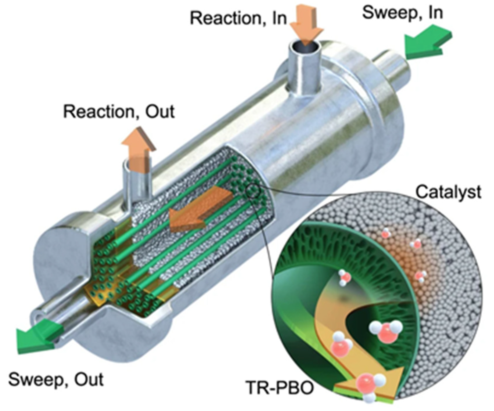
  120. Li, Z.; Deng, Y.; Dewangan, N.; Hu, J.; Wang, Z.; Tan, X.; Liu, S.; Kawi, S. High Temperature Water Permeable Membrane Reactors for CO2 Utilization. Chem. Eng. J. 2021, 420, 129834. [Google Scholar] [CrossRef]
  121. Hyeon, M.-H.; Park, H.-G.; Lee, J.; Kong, C.-I.; Kim, E.-Y.; Kim, J.H.; Moon, S.-Y.; Kim, S.K. Equilibrium shift, poisoning prevention, and selectivity enhancement in catalysis via dehydration of polymeric membranes. Nat. Commun. 2023, 14, 1673. [Google Scholar] [CrossRef] [PubMed]
  122. Meiri, N.; Radus, R.; Herskowitz, M. Simulation of novel process of CO2 conversion to liquid fuels. J. CO2 Util. 2017, 17, 284–289. [Google Scholar] [CrossRef]
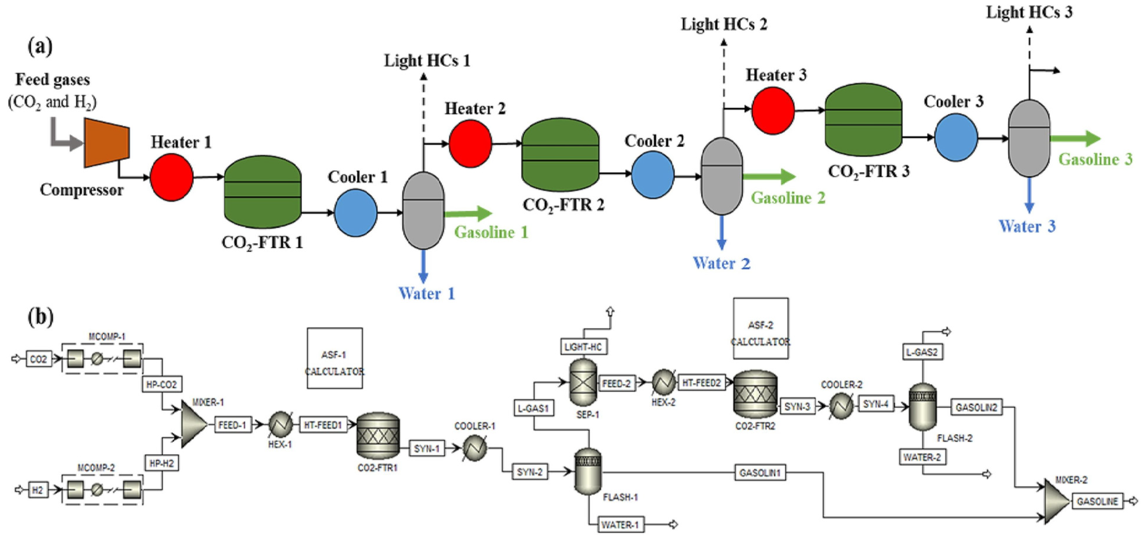
  123. Kamkeng, A.D.N.; Wang, M. Technical analysis of the modified Fischer-Tropsch synthesis process for direct CO2 conversion into gasoline fuel: Performance improvement via ex-situ water removal. Chem. Eng. J. 2023, 462, 142048. [Google Scholar] [CrossRef]
  124. van Bavel, S.; Verma, S.; Negro, E.; Bracht, M. Integrating CO2 Electrolysis into the Gas-to-Liquids–Power-to-Liquids Process. ACS Energy Lett. 2020, 5, 2597–2601. [Google Scholar] [CrossRef]
  125. Fakhroleslam, M.; Sadrameli, S.M. Thermal/catalytic cracking of hydrocarbons for the production of olefins; a state-of-the-art review III: Process modeling and simulation. Fuel 2019, 252, 553–566. [Google Scholar] [CrossRef]
  126. Do, T.N.; Kim, J. Green C2-C4 hydrocarbon production through direct CO2 hydrogenation with renewable hydrogen: Process development and techno-economic analysis. Energy Convers. Manag. 2020, 214, 112866. [Google Scholar] [CrossRef]
  127. Adelung, S.; Maier, S.; Dietrich, R.-U. Impact of the reverse water-gas shift operating conditions on the Power-to-Liquid process efficiency. Sustain. Energy Technol. Assess 2021, 43, 100897. [Google Scholar] [CrossRef]
  128. Cinti, G.; Baldinelli, A.; Di Michele, A.; Desideri, U. Integration of Solid Oxide Electrolyzer and Fischer-Tropsch: A sustainable pathway for synthetic fuel. Appl. Energy 2016, 162, 308–320. [Google Scholar] [CrossRef]
  129. Gao, R.; Zhang, C.; Jun, K.-W.; Kim, S.K.; Park, H.-G.; Zhao, T.; Wang, L.; Wan, H.; Guan, G. Green liquid fuel and synthetic natural gas production via CO2 hydrogenation combined with reverse water-gas-shift and co-based Fischer-Tropsch synthesis. J. CO2 Util. 2021, 51, 101619. [Google Scholar] [CrossRef]
  130. Gao, R.; Zhang, C.; Jun, K.-W.; Kim, S.K.; Park, H.-G.; Zhao, T.; Wang, L.; Wan, H.; Guan, G. Transformation of CO2 into liquid fuels and synthetic natural gas using green hydrogen: A comparative analysis. Fuel 2021, 291, 120111. [Google Scholar] [CrossRef]
  131. Gao, R.; Wang, L.; Zhang, L.; Zhang, C.; Jun, K.-W.; Ki Kim, S.; Park, H.-G.; Zhao, T.; Gao, Y.; Zhu, Y.; et al. Upcycling of CO2 into sustainable hydrocarbon fuels via the integration of Fe-based Fischer-Tropsch synthesis and olefin oligomerization: A comparative case study. Fuel 2022, 325, 124855. [Google Scholar] [CrossRef]
  132. Gao, R.; Zhang, L.; Wang, L.; Zhang, C.; Jun, K.-W.; Kim, S.K.; Park, H.-G.; Gao, Y.; Zhu, Y.; Wan, H.; et al. Efficient production of renewable hydrocarbon fuels using waste CO2 and green H2 by integrating Fe-based Fischer-Tropsch synthesis and olefin oligomerization. Energy 2022, 248, 123616. [Google Scholar] [CrossRef]
  133. Dahiru, A.R.; Vuokila, A.; Huuhtanen, M. Recent development in Power-to-X: Part I-A review on techno-economic analysis. J. Energy Storage 2022, 56, 105861. [Google Scholar] [CrossRef]
  134. Herz, G.; Reichelt, E.; Jahn, M. Techno-economic analysis of a co-electrolysis-based synthesis process for the production of hydrocarbons. Appl. Energy 2018, 215, 309–320. [Google Scholar] [CrossRef]
  135. Markowitsch, C.; Lehner, M.; Maly, M. Evaluation of process structures and reactor technologies of an integrated power-to-liquid plant at a cement factory. J. CO2 Util. 2023, 70, 102449. [Google Scholar] [CrossRef]
  136. Pratschner, S.; Hammerschmid, M.; Müller, F.J.; Müller, S.; Winter, F. Simulation of a Pilot Scale Power-to-Liquid Plant Producing Synthetic Fuel and Wax by Combining Fischer–Tropsch Synthesis and SOEC. Energies 2022, 15, 4134. [Google Scholar] [CrossRef]
  137. Marchese, M.; Giglio, E.; Santarelli, M.; Lanzini, A. Energy performance of Power-to-Liquid applications integrating biogas upgrading, reverse water gas shift, solid oxide electrolysis and Fischer-Tropsch technologies. Energy Convers. Manag. X 2020, 6, 100041. [Google Scholar] [CrossRef]
  138. Pratschner, S.; Hammerschmid, M.; Müller, S.; Winter, F. Evaluation of CO2 sources for Power-to-Liquid plants producing Fischer-Tropsch products. J. CO2 Util. 2023, 72, 102508. [Google Scholar] [CrossRef]
  139. GmbH, S. Breakthrough for Power-to-X: Sunfire Putsfirst Co-Electolysis into Operation and Starts Scaling. Available online: https://www.sunfire.de/en/news/detail/breakthrough-for-power-to-x-sunfire-puts-first-co-electrolysis-into-operation-and-starts-scaling (accessed on 29 May 2023).
  140. Colelli, L.; Segneri, V.; Bassano, C.; Vilardi, G. E-fuels, technical and economic analysis of the production of synthetic kerosene precursor as sustainable aviation fuel. Energy Convers. Manag. 2023, 288, 117165. [Google Scholar] [CrossRef]
  141. Schemme, S.; Breuer, J.L.; Köller, M.; Meschede, S.; Walman, F.; Samsun, R.C.; Peters, R.; Stolten, D. H2-based synthetic fuels: A techno-economic comparison of alcohol, ether and hydrocarbon production. Int. J. Hydrog. Energy 2020, 45, 5395–5414. [Google Scholar] [CrossRef]
  142. Zhao, J.; Yu, Y.; Ren, H.; Makowski, M.; Granat, J.; Nahorski, Z.; Ma, T. How the power-to-liquid technology can contribute to reaching carbon neutrality of the China’s transportation sector? Energy 2022, 261, 125058. [Google Scholar] [CrossRef]
  143. Adelung, S.; Dietrich, R.-U. Impact of the reverse water-gas shift operating conditions on the Power-to-Liquid fuel production cost. Fuel 2022, 317, 123440. [Google Scholar] [CrossRef]
  144. Gao, R.; Zhang, L.; Wang, L.; Zhang, C.; Jun, K.-W.; Kim, S.K.; Park, H.-G.; Zhao, T.; Wan, H.; Guan, G. Efficient utilization of CO2 in power-to-liquids/power-to-gas hybrid processes: An economic-environmental assessment. J. CO2 Util. 2023, 68, 102376. [Google Scholar] [CrossRef]
  145. Adelung, S. Global sensitivity and uncertainty analysis of a Fischer-Tropsch based Power-to-Liquid process. J. CO2 Util. 2022, 65, 102171. [Google Scholar] [CrossRef]
  146. Fasihi, M.; Bogdanov, D.; Breyer, C. Techno-economic assessment of power-to-liquids (PtL) fuels production and global trading based on hybrid PV-wind power plants. Energy Procedia 2016, 99, 243–268. [Google Scholar] [CrossRef] [Green Version]
  147. Zhang, C.; Gao, R.; Jun, K.-W.; Kim, S.K.; Hwang, S.-M.; Park, H.-G.; Guan, G. Direct conversion of carbon dioxide to liquid fuels and synthetic natural gas using renewable power: Techno-economic analysis. J. CO2 Util. 2019, 34, 293–302. [Google Scholar] [CrossRef]
Figure 1. The schematic diagram of membrane separation [52]. Copyright (2017) Recent Advances in Carbon Capture and Storage.
Processes 11 02089 g001
Figure 2. The schematic diagram of co-electrolysis of H2O and CO2 [94]. Copyright (2017) International Journal of Hydrogen Energy.
Processes 11 02089 g002
Figure 3. Schematic diagram of the membrane reactor module [121]. Copyright (2023) Nat Commun.
Processes 11 02089 g003
Figure 4. Schematic diagram of CO2 hydrogenation to liquid fuel process with three reactors in series (a) Configuration concept and (b) process simulation of CO2-FTS to gasoline using three reactors in series [123]. Copyright (2023) Chemical Engineering Journal.
Processes 11 02089 g004
Figure 5. Process flow diagram of the C2–C4 hydrocarbon production process [126]. Copyright (2020) Energy conversion and Management.
Processes 11 02089 g005
Figure 6. The schematic process flowsheet of the CO2 hydrogenation to liquid fuels process coupled with methanation technology [129]. Copyright (2021) Journal of CO2 Utilization.
Processes 11 02089 g006
Figure 7. The simplified process flowsheet of the two-staged CO2 hydrogenation to liquid fuels [131]. Copyright (2022) Fuel.
Processes 11 02089 g007
Figure 8. Schematic diagram of the hybrid PTL/PTG process coupled with different water electrolysis technologies [8]. Copyright (2022) Energy Conversion and Management.
Processes 11 02089 g008
Figure 9. Process flow diagram of the PTL process coupled with co-electrolysis technology [137]. Copyright (2020) Energy Conversion and Management: X.
Processes 11 02089 g009
Figure 10. Schematic diagram of the PTL process with different CO2 sources [138]. Copyright (2023) Journal of CO2 Utilization.
Processes 11 02089 g010
Figure 11. Schematic diagram of the direct (left) and indirect (right) PTL processes [140]. Copyright (2023) Energy Conversion and Management.
Processes 11 02089 g011
Table 1. Comparison of various physical solvents used in acid gas separation.
Physical Absorption MethodMajor SolventOperating Requirements, Advantages, and Limitations:
RectisolMethanol
(1)
Deep refrigeration.
(2)
Water washing of effluent streams to prevent high solvent losses.
Limitations: Higher selectivity for H2S over CO2.
SelexolPolyethylene glycol dimethyl ether
(1)
Highest CO2 solubility among physical solvents.
(2)
Operate at a broad temperature range: from 0 to 175 °C.
(3)
Low cost than Rectisol.
Limitations: Higher viscosity than most physical solvents.
FluorPropylene Carbonate
(1)
Higher vapor pressure than Selexol.
(2)
Low solvent losses.
(3)
Operating temperature is below 65 °C.
Limitations: Poor sulfur resistance.
Disclaimer/Publisher’s Note: The statements, opinions and data contained in all publications are solely those of the individual author(s) and contributor(s) and not of MDPI and/or the editor(s). MDPI and/or the editor(s) disclaim responsibility for any injury to people or property resulting from any ideas, methods, instructions or products referred to in the content.

