1. Introduction
The afterburner is an important part of military aeroengines. Its primary function is to quickly increase the engine’s thrust in a short time, so as to ensure that fighter jets gain speed advantages when taking off at short distances, fighting at close range, chasing enemies, penetrating defenses, or escaping [
1]. Usually, the maximum thrust of a military turbojet engine can reach about 1.5 times that when the afterburner is turned on, while that of a military turbofan engine can be as high as 1.8 times. To some extent, the regular operation of the afterburner is directly related to the life and death of fighter jets. However, in the actual working process, many engines have experienced faults in which the afterburner cannot be connected in the test run and actual service [
2,
3]. Due to the complex working environment of the engine under the afterburner state, many factors cause the fault. How to quickly implement fault diagnosis and troubleshooting is a major challenge for military aeroengines in their entire life cycle.
Currently, there is a proliferation of studies concerning the fault diagnosis of aeroengines. Rath provides an overview of the recent developments in the field of aircraft engine health monitoring, diagnostics, and prognostics based on aerodynamic performance parameters in detail. It presents a recommendation to utilize engine model performance adaptation to establish high-quality databases, aiming to enhance the diagnostic capabilities for engine faults [
4]. The efficacy of these fault diagnosis algorithms heavily relies on an abundant and precise collection of measurement data. However, due to the constraints imposed by the high-temperature and high-pressure conditions within the augmented combustion chamber, the installation of sensors is profoundly restricted [
5]. Consequently, the focal point of research in augmented combustion chamber fault diagnosis lies in the exploration of onboard models or advanced measurement techniques as means to further acquire the requisite data.
Moreover, these primarily utilize three methodologies: a diagnostic approach rooted in signal processing, a diagnostic process informed by analytical modeling, and an intelligent diagnostic strategy underpinned by knowledge-based systems [
6]. Mikael Stenfelt appraises two distinct methodologies for assessing burn-through in afterburner linings: one approach is model-centric, while the other is predicated on data analysis [
7]. Seyfried Hans investigates the utilization of optical/laser-based methodologies for the evaluation of an afterburner in a comprehensive aircraft engine [
8], with the aim of examining the prospective benefits of such techniques for advanced afterburner diagnosis. Yang Fugang [
9], Zhang Fan [
10], and others used the fault tree analysis method to analyze the typical faults of the aeroengine afterburner control system and afterburner turn-on delay faults and realized the diagnosis and elimination of faults. George [
11] presented a novel temperature probe design for measuring exhaust gas temperature (EGT) in a turbofan engine in afterburner mode, along with error estimation and correction methodologies, and successfully reduced the measurement error to 24 K, attributing the remaining difference to thermocouple error, other parameter measurement errors, and analysis uncertainties. The diagnosis and analysis of these faults are mainly to find out the afterburner characteristic description of the fault and use this feature to carry out fault detection, prediction, separation, identification, and then realize fault decision making.
However, the failure mechanism of the afterburner chamber is exceptionally complex. The reasons for the failure of the afterburner in aviation engines may include dramatic changes in the aerodynamic and thermal performance of the engine itself, as well as the lack of adaptive improvements in the flame stabilizer structure [
12]. Moreover, faults may also originate from a variety of factors such as anomalies in the electronic and electrical systems, and oil and gas mismatch. Bokwon presents an investigation into the causes and analytical process of augmented nozzle failures in a particular fighter aircraft during flight. The research findings demonstrate a correlation between the occurrence of faults and multiple factors [
13,
14]. It is worth noting that the afterburner operates in the most demanding stage of the aviation engine, with limited measurable signals. Therefore, it is challenging to capture the symptoms of failure. The failure of the afterburner to engage may occur suddenly, and it is difficult to detect apparent signs before it happens. On the other hand, Safdar presents a computational fluid dynamics analysis of the turbulent flow characteristics and performance estimation of a low bypass ratio turbofan engine’s afterburner [
15]. Kattegollahalli [
16] and Shakil’s [
17] works utilize computational fluid dynamics (CFD) simulations to predict the performance of an aircraft engine afterburner under varying altitude conditions and reheat strengths, which demonstrates that CFD has proven to be a reliable and accurate tool for indirectly observing the internal aerodynamics of an afterburner and assessing its performance with good precision. Therefore, traditional fault diagnosis algorithms relying solely on measurement signals face challenges in accurately capturing and identifying afterburner faults. Integrating CFD-based calculations for afterburner fault diagnosis presents a more viable approach.
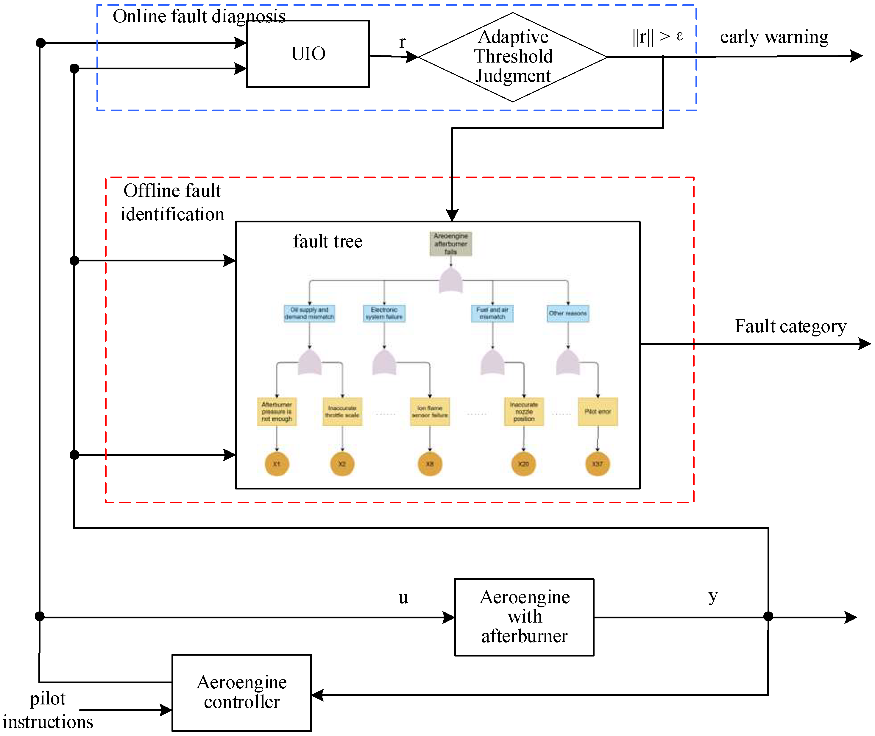
The salient novelties and contributions in this paper are summarized as follows: the paper addresses the important issue of fault diagnosis and troubleshooting in the afterburner of military aeroengines. It presents a hybrid diagnostic fault architecture that combines traditional observer fault diagnosis with fault trees for online fault diagnosis of critical faults in the afterburner. The main contribution of the paper lies in the construction of a fault tree for afterburner engagement failures, the use of computational fluid dynamics (CFD) for numerical analysis of the afterburner structure and measurement scheme, and the proposal of a hybrid diagnostic fault architecture for precise fault identification and elimination. The study provides a theoretical basis and practical guidance for afterburner fault diagnosis in aviation.
This paper is organized as follows. In
Section 2, descriptions of the aeroengine afterburner switch-on principle are formulated.
Section 3 proposes fault diagnosis methods based on the fault tree, and it includes construction of an aircraft afterburner failure tree, an online fault diagnosis algorithm of an ion flame sensor, an adaptive threshold design for fault diagnosis, and a fusion of fault tree and observer for fault diagnosis. In
Section 5, testbed examples and are given to illustrate the proposed method is effective. The conclusions of this work are drawn finally in
Section 5.
2. Aeroengine Afterburner Switch-On Principle
The afterburner system in an aircraft engine typically consists of two main components: an electronic integrated regulator and an afterburner fuel adjustment system. The integrated regulator is primarily responsible for adjusting engine parameters and issuing instructions to control accessories. On the other hand, the afterburner fuel adjustment system connects to the throttle lever signal, which enables it to control the fuel supply to the afterburner and cut it off when necessary. This design allows the engine afterburner to enter the minimum afterburner state as per the comprehensive adjustment command.
When the pilot pushes the throttle stick to the afterburner zone to activate the afterburner, the oil pressure in the signal indicator will rise to a certain threshold to activate the signal indicator. Then, the signal indicator will send an afterburner turn-on command to the integrated regulator. The afterburner control component of the integrated regulator will control the operation of the electromagnetic valve of the quantitative regulator through a series of three pulses, with an ON duration of (0.3 ± 0.1) s and an OFF duration of (0.5 ± 0.2) s. Suppose the afterburner fuel ignites within these three pulses. In that case, the afterburner control component will receive the feedback signal and immediately interrupt the operation of the electromagnetic valve, stopping the pulse fuel supply and entering the open-loop adjustment of the afterburner fuel quantity. However, if the afterburner ignition fails, the pilot can retract the throttle stick to the non-afterburner zone and then push the throttle stick to the afterburner zone again to activate the ignition system and allow the pilot to try again.
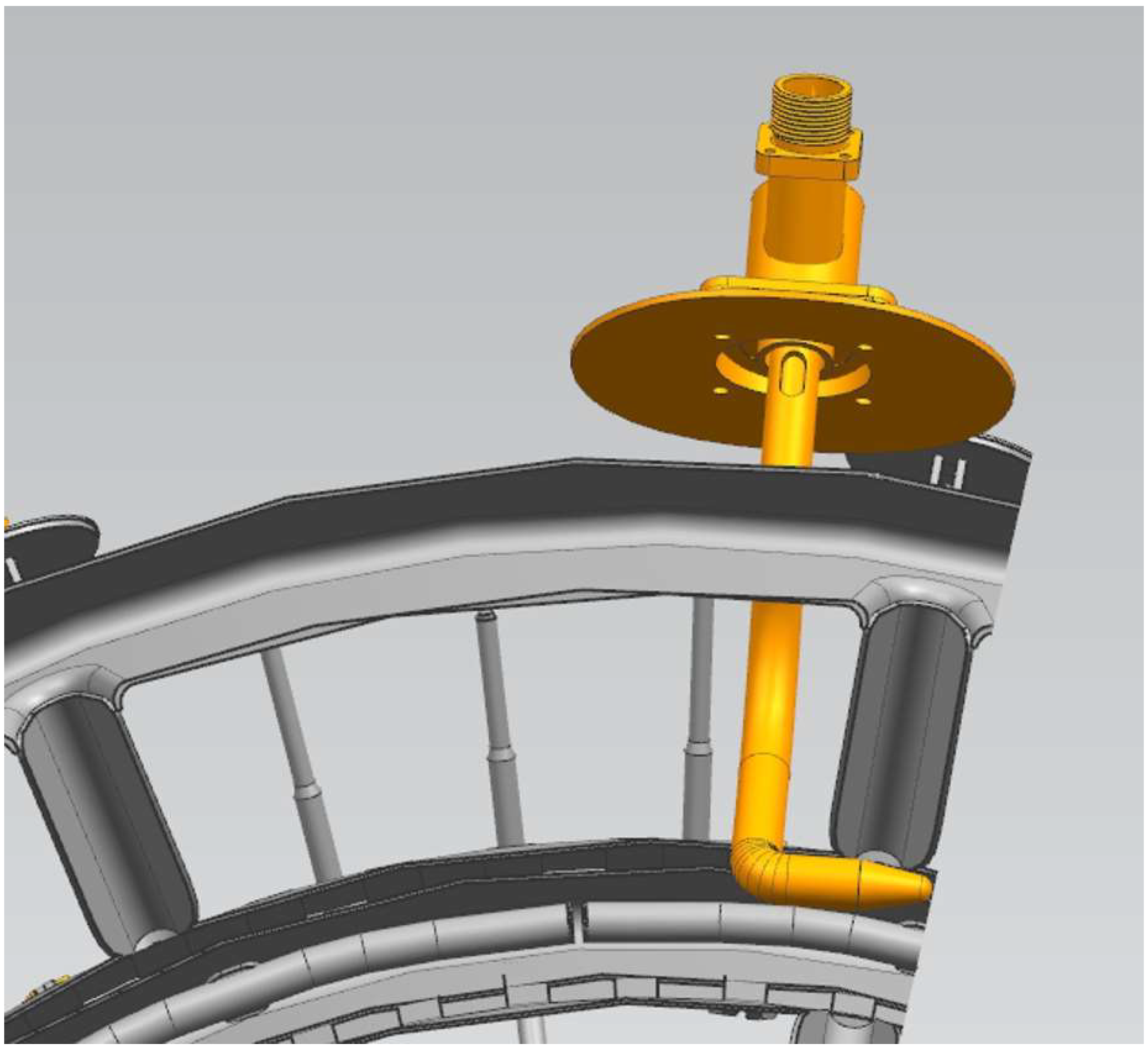
During this process, the ion flame sensor is critical in determining whether the afterburner has been successfully ignited. The ion flame sensor is installed under the diffuser casing, with the suitable sensor used to detect whether there is a flame in the combustion area of the afterburner pre-combustion chamber and the left sensor used to detect the flame in the flame stabilizer part of the outer ring of the afterburner, as shown in
Figure 1. When the ion flame sensor detects the flame signal in the afterburner, it outputs a current. If the output current reaches a certain threshold and lasts for a specific period, the integrated regulator will judge that the afterburner has been ignited. On the contrary, if the throttle lever is pushed into the afterburner range to engage the afterburner, but the output current of the ion flame sensor still fails to reach the set threshold, it will be considered that the afterburner has not been turned on, and a 5 Hz flashing signal will be sent to the aircraft cockpit to alert the pilot.
However, in the actual operation of an aircraft engine, the ion flame sensor may not be able to accurately characterize the actual connection status of the afterburner due to various complicated reasons. For instance, during the working process of an aircraft equipped with a specific type of aeroengine, the ionization current value of the flame ion sensor was lower than the set threshold due to unknown interference when the engine was in a state of small afterburner, even though it was actually turned on. This misjudgment of “small afterburner is not connected” restricts the afterburner electromagnetic valve, which cannot be released later. As a result, the engine’s nozzle remains in the “small afterburner” state, and the full afterburner oil delivery ring does not supply oil, which prevents the engine from connecting to the “full afterburner” state, almost leading to a significant accident. Therefore, real-time monitoring of afterburner non-connection faults, such as those related to the ion flame sensors, can effectively improve the reliability of aeroengines.
3. Fault Diagnosis Method Based on Fault Tree
3.1. Construction of Afterburner Failure Tree
The afterburner control system of the aeroengine is quite complicated. On the one hand, the inlet gas pressure of the afterburner is low, the wind speed is low, the oxygen content is low, and the ignition conditions are poor. On the other hand, it contains a lot of components. A typical afterburner control system includes power regulators, integrated regulators, nozzle oil source pumps, ion flame detectors, afterburner fuel distributors, etc. Based on this, the fault tree analysis method for complex safety systems, reliability analysis, fault diagnosis, and risk assessment is practical for fault diagnosis and elimination of afterburner failure [
18,
19,
20].
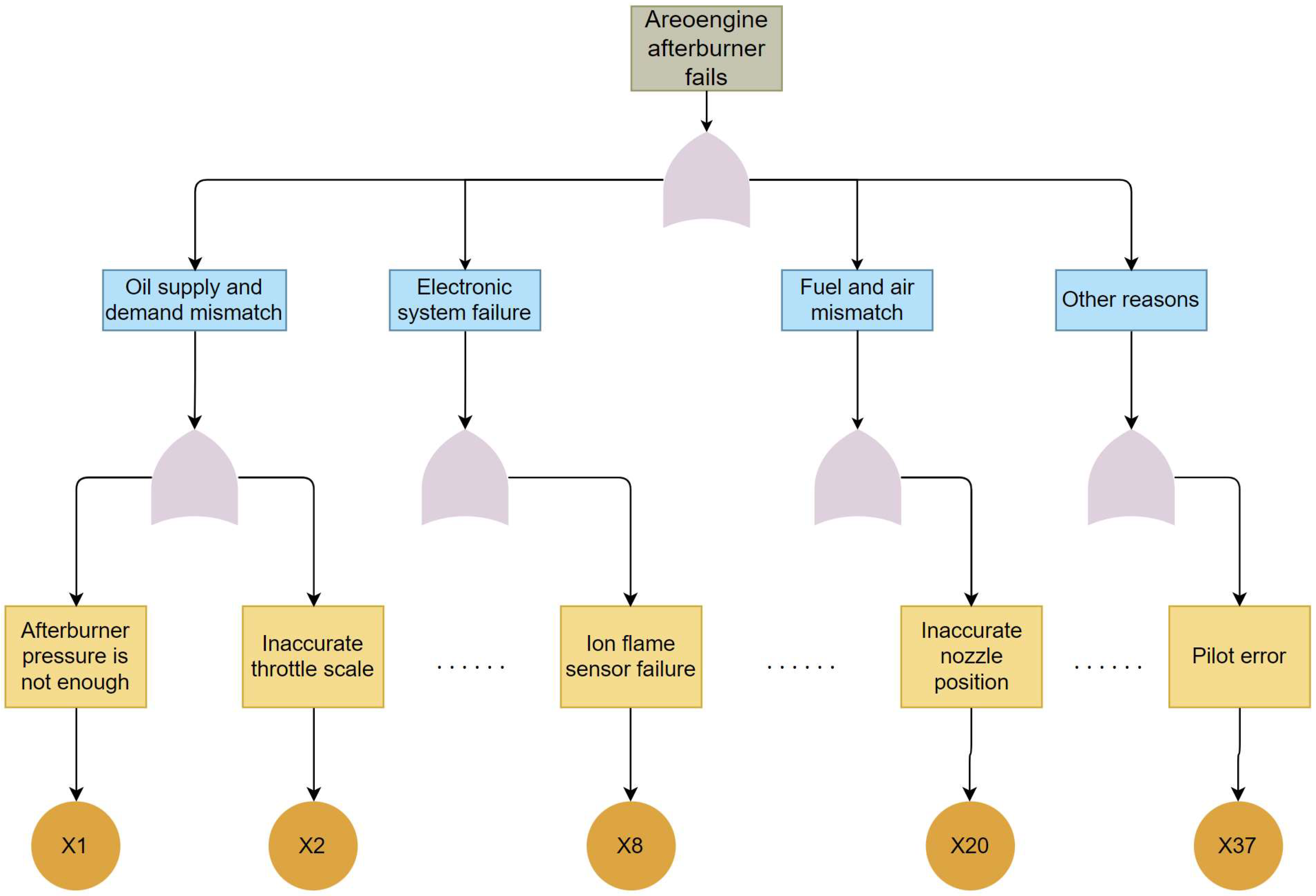
After the statistical analysis of “a certain series of engine afterburner not connected” failures, the main reasons for the failure of engine afterburner to be connected are the mismatch between supply and demand of oil, the abnormality of electronic and electrical systems, the mismatch of oil and gas, and other related reasons. The specific analysis of these four types of reasons can be more in depth, and all the reasons why the engine afterburner cannot be connected can be traced back. Based on this, the fault tree of a specific series of engine afterburner failures is compiled, as shown in
Figure 2.
Among them, circles represent basic events, and rectangles represent intermediate events and the top events. The whole fault tree model includes 37 basic events, 61 intermediate events, and 14 logic gates.
After sorting out the entire fault tree model, this study finds that the ion flame sensor fault is the fault with the highest probability of occurrence and the greatest danger in the fault tree, and the ion flame sensor is easily affected by interference such as structure, installation location, and air intake flow of the aeroengine. It is necessary to construct an online fault diagnosis algorithm with strong anti-interference ability.
3.2. Online Fault Diagnosis Algorithm of Ion Flame Sensor
Due to various interference factors that will appear in the afterburner ignition process of the aeroengine, based on the design point of the afterburning of the aeroengine, this paper considers the following linear system model:
where
is the system state vector,
is the control vector,
is the external disturbance,
is the system measurement output including the ion flame sensor current value,
is the time-varying unknown ion flame sensor fault signal. The unknown interference, such as the installation position of the neutral ion flame sensor, the air intake flow of the aeroengine, and the non-measurable noise of the system, is considered.
The unknown input observer (UIO) is designed as follows:
It makes the state estimation
asymptotically approach the real state of the system and is not affected by the disturbance
. The basic idea of the UIO is to realize the asymptotic observation
by minimizing the effect from the disturbance
on the state estimation bias
. For the specific calculation method of UIO parameters, please refer to [
21,
22].
There has been a lot of research on the application of UIOs in aeroengines, so the design of UIOs is not a problem.
Then, we only need to monitor the magnitude of the residual signal vector of the current value of the ion flame sensor to realize the detection of the fault of the ion flame sensor system. Theoretically, when there is no fault, the residual should be approximately zero, and when there is a fault, the residual will deviate from zero. Due to the influence of structural modification, installation location, air intake flow of the aeroengine, etc. in practice, it is difficult to keep the residual error at a zero value in the case of no faults, so the method of threshold is used for a robust design. The specific fault detection logic is as follows:
where
is the detection threshold,
corresponds to no fault,
corresponds to fault.
The specific setting of the detection threshold has a great influence on the effectiveness of fault detection. If the threshold is set too low, it is prone to false alarms. If the threshold is set too high, it is prone to generate missed alarms.
3.3. Adaptive Threshold Design for Fault Diagnosis
When a modified engine of this series is tested on the bench in the factory or installed in the army, there is a unique phenomenon: the ionization current value (I right) of the flame ion sensor on the right side is relatively small in the state of a small afterburner. The ionization current value of some engines is too small, causing the digital regulator to believe that the “afterburner is not connected” mistakenly (actually, it is connected, one can stand behind the aircraft and observe a blue flame in the pre-combustion chamber). It is impossible to continue to release the minimum afterburner electromagnetic valve limit (full afterburner). The fuel injection pipe does not inject fuel. The nozzle remains in the “small afterburner” state. After a while, the control system automatically “cuts off” the fuel supply in the small afterburner state, which leads to the failure of the afterburner to be connected. The inability to achieve a “small afterburner state” to a “full afterburner state” leads to failure of the afterburner connection, which can easily interrupt take-off. The aircraft fails to take off and crashes out of the runway, which is extremely harmful.
Compared with the original batch of engines, the total amount of intake air of the modified batch of engines is increased. Airflow increased by 5%, and engine bypass ratio increased by 9%, so that the gas flow velocity through the afterburner stabilizer in the combustion chamber increases. As the gas flow rate increased, the flow field and temperature field in the afterburner chamber changed from those in the original batch. However, the shape and size of the stabilizer were not optimized and improved during the modification, resulting in the position of the afterburner flame peak after the stabilizer being different from that of the original batch of engines. During the retrofit, the installation position of the flame ion sensor was not adaptively optimized, so that the position of the sensing part of the sensor did not overlap with the position of the afterburner flame peak, and the sensor could not sense the highest temperature area, resulting in a small ionization current value.
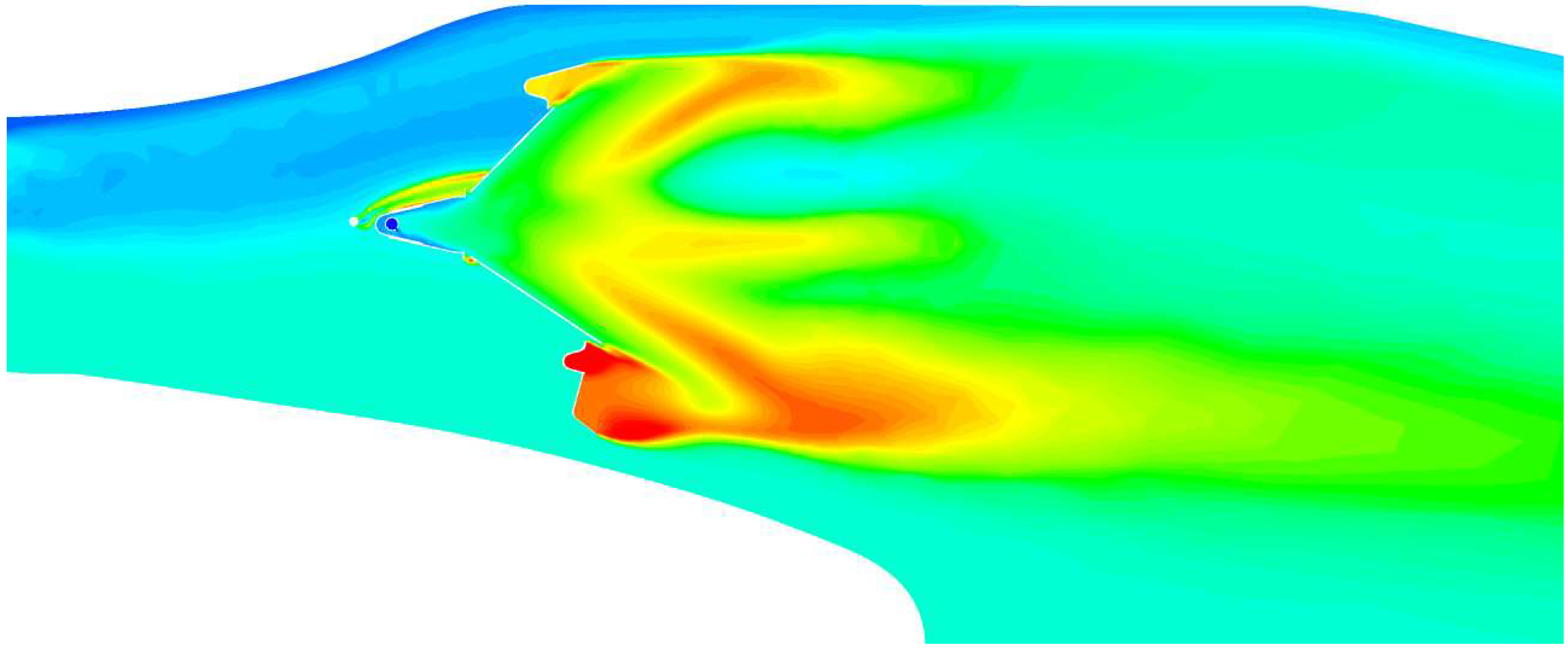
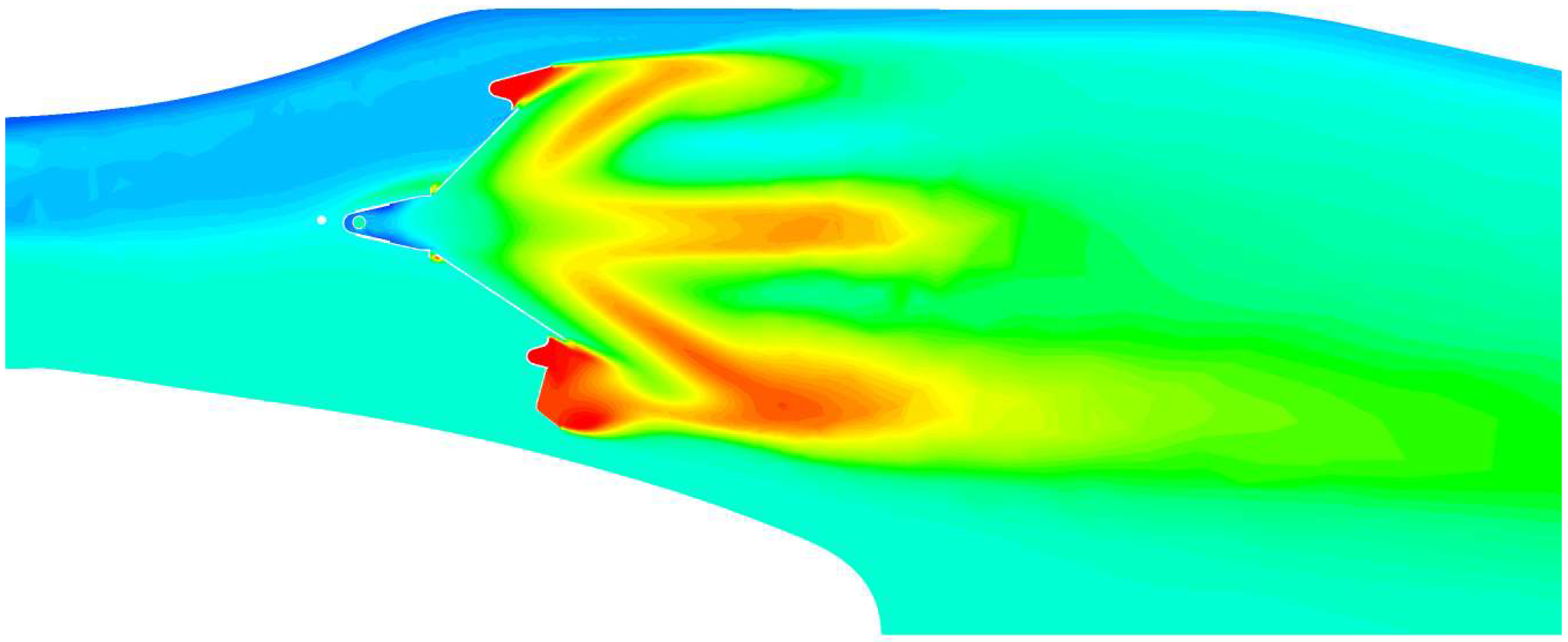
Through the numerical simulation analysis and calculation, the difference in the flow field and temperature field distribution between the modified batch engine and the original batch engine stabilizer and the flow field and temperature field distribution changes of the modified batch engine stabilizer before and after calibration are compared with two models by conducting an in-depth study, as respectively shown in
Figure 3,
Figure 4 and
Figure 5. Through numerical simulation, it can be found that compared to the original batch engines, the modified batch engines have increased intake airflow. If the flame ion sensor position and the surrounding stabilizer of the modified batch engines are not adequately optimized for adaptation, the airflow velocity passing through the stabilizer will be greater. This causes the entire stable combustion zone to move backward, resulting in the expected high-temperature zone of the afterburner flame not aligning with the sensing element of the sensor. As a result, the actual high-temperature zone sensed by the sensor is displaced from the real flame temperature by over 100 degrees Celsius, leading to a decrease in ionization current value.
Stabilizer calibration technology can eliminate the failure of the machine afterburners. At the same time, it allows for a greater mixture of air on both sides of the sensing element of the flame ion sensor with the atomized fuel at the sensing element position. This results in a more thorough atomization of the fuel at the sensing element position, higher oxygen content, and more complete combustion. As a result, the sensing element of the flame ion sensor can more accurately measure the actual temperature of the afterburner combustion chamber, enabling precise monitoring of whether the afterburner combustion chamber is operating in a normal working condition. According to the calculation results of the model, the V-shaped opening is narrowed by 5 mm, and the local temperature is increased by about 100 degrees Celsius.
3.4. Fusion of Fault Tree and Observer for Fault Diagnosis
A troubleshooting flow chart is drawn based on the specific fault phenomenon of a modified engine afterburner failure and the fault tree of afterburner failure. As shown in
Figure 4, the engine generally has the phenomenon that the current value of the ion flame sensor is too small, and it can be inferred that the flame ion sensor is a crucial part of fault analysis. The small current value is the direct cause of the failure of the engine afterburner to be connected. It can basically be determined that the electronic and electrical system is abnormal, and the reasons, such as the mismatch between the supply and demand of oil and the mismatch between oil and gas, are excluded. According to the troubleshooting flow chart as shown in
Figure 6, it is checked whether the ion flame sensor of this batch of engines has abnormal resistance values. After the measurement, it shows that the ion flame sensor is working normally. Checking of the sensing part of the ion flame sensor is continued. No carbon deposits are found, indicating that the ion flame sensor’s flame intensity at the sensing part is insufficient, and the flow field and temperature field in the afterburner chamber of the modified engine have changed compared with the original model. Considering the calibration of the flame stabilizer, the radial stabilizers on the upper and lower sides of the flame ion sensor are calibrated. The opening of the flame stabilizer is shrunk to expand the recognition range of the sensing part of the sensor. After calibration, the ionization current value of the sensor increases, and the failure of the afterburner connection is eliminated. According to the established fault tree and troubleshooting flow chart for afterburner connection failure, the fault location where the afterburner is not working when the afterburner is connected is quickly found, which provides helpful guidelines for troubleshooting the engine test run.
4. Experimental Verification
In order to verify the methodology proposed in this paper, three engines (No. 1, No. 2, and No. 3) that had experienced combustion chamber malfunctions were selected from a batch of aircraft engines. During the initial engine testing on the test bench, all three engines displayed warnings indicating ignition failure despite successful ignition of the combustion chamber. Utilizing the UIO developed in this study, online warnings were provided. Through fault tree analysis, the identified root cause was determined to be “abnormal flame sensor current readings”. The flame sensor current values for these engines are presented in
Table 1. To facilitate experimental analysis, the flame sensor current values were normalized as outlined in this paper. For this particular type of aircraft engine, the threshold for determining successful boost connection is set at (100 ± 5)%. It is evident from
Table 1 that the measured flame sensor current values for these faulty aircraft engines are lower than expected.
As described in the aforementioned analysis in
Section 3.3, the correlated cause analysis based on the fault tree revealed that the variation in the intake airflow of these engines resulted in changes in the temperature field surrounding the flame sensor of the boost combustion chamber. Consequently, false alarms were triggered, indicating the boost combustion chamber’s failure to operate correctly.
To address this, the present study conducted an additional six test runs on the ground test bench for these three engines. Throughout the experimental process, the position of the flame ionization sensor was continuously adjusted, and the calibrated flame sensor current values were calculated. The experimental results are presented in
Table 2. Through the calibration of the flame ionization sensor’s installation position, the final current values for all three engines remained above the threshold value, indicating normal operation of the boost combustion chamber.
For Aeroengine No. 1, which experienced significant changes in the intake airflow, three adjustments were made. However, based on the results of each adjustment, the minimum current value steadily increased. Eventually, it was ensured to be above the threshold of 100%, thereby validating the effectiveness of the analytical methodology proposed in this paper.
5. Conclusions
Accurate assessment of the proper functioning of the augmenter combustion chamber is of utmost importance for the operation of an aircraft engine. Therefore, this paper has embarked on an exploration of integrating traditional observer design, CFD analysis, and fault tree analysis to achieve fault monitoring of the augmenter combustion chamber in aviation engines.
Firstly, this paper proposes a hybrid diagnostic fault architecture that combines traditional observer-based fault diagnosis with fault tree analysis. This architecture utilizes traditional observers to monitor the real-time operation of the augmenter combustion chamber and integrates fault tree analysis to achieve accurate fault diagnosis through fault reasoning and determination. By incorporating CFD analysis, we are able to simulate and predict the working conditions of the augmenter combustion chamber more accurately, thereby enhancing the accuracy and reliability of fault diagnosis.
Secondly, this study conducted multiple rounds of ground-based testing on the augmenter combustion chamber of aviation engines. Experimental results demonstrate that the performance of the augmenter combustion chamber is influenced by the intake airflow rate and the installation position of the ion flame sensors. During the testing process, we observed that a mismatch between the intake airflow rate and the design parameters of the combustion chamber could potentially lead to false alarms in the detection of augmenter combustion chamber faults. Similarly, an incorrect installation position of the ion flame sensors can also affect the accuracy of fault diagnosis. Therefore, in practical applications, it is crucial to ensure the compatibility of the intake airflow rate and the installation position of the ion flame sensors with the design parameters of the combustion chamber to reduce the possibility of false alarms.
In conclusion, this study proposes a hybrid diagnostic fault architecture by integrating traditional observer design, CFD analysis, and fault tree analysis, enabling accurate fault diagnosis of the augmenter combustion chamber in aviation engines. We also emphasize the importance of considering the compatibility between intake airflow rate, ion flame sensor installation position, and combustion chamber design parameters in practical applications to enhance the reliability and accuracy of fault diagnosis. These research findings hold significant implications for ensuring the normal operation and safety of aircraft engines.
Author Contributions
Conceptualization, Q.Z. and M.G.; methodology, A.H.; software, P.X.; validation, Y.Z., J.L. and Q.Z.; formal analysis, A.H.; investigation, A.H.; resources, Q.Z.; data curation, Q.Z.; writing—original draft preparation, A.H.; writing—review and editing, A.H.; visualization, Q.Z.; supervision, Q.Z.; project administration, A.H.; funding acquisition, Q.Z. All authors have read and agreed to the published version of the manuscript.
Funding
This research was funded by Science Center for Gas Turbine Project of China, grant number 2022-A-II-005 and Tsinghua University Initiative Scientific Research Program. The APC was funded by Science Center for Gas Turbine Project of China.
Data Availability Statement
Where data is unavailable due to privacy or ethical restrictions.
Acknowledgments
This study was supported by the Science Center for Gas Turbine Project of China (Grant No. 2022-A-II-005).
Conflicts of Interest
The authors declare no conflict of interest.
References
- Gan, X.; Xue, H.; Lei, Y. General Theory of Aeroengine Engineering; Beijing Institute of Technology Press: Beijing, China, 2021. [Google Scholar]
- Mohammadi, R.; Hashtrudi-Zad, S.; Khorasani, K. Hybrid fault diagnosis: Application to a gas turbine engine. In Proceedings of the Turbo Expo: Power for Land, Sea, and Air, Orlando, FL, USA, 8–12 June 2009; pp. 719–729. [Google Scholar]
- Yi, C. Fault analysis of a certain type of engine afterburner failure. China Equip. Eng. 2020, 1, 107–109. [Google Scholar]
- Rath, N.; Mishra, R.K.; Kushari, A. Aero engine health monitoring, diagnostics and prognostics for condition-based maintenance: An overview. Int. J. Turbo Jet-Engines 2022, 34, 1–73. [Google Scholar] [CrossRef]
- Zhang, X.; Sun, Y.; Liu, T. Summary of Advanced Afterburner Design Technology. J. Aeroengine 2014, 40, 24–30. [Google Scholar]
- Yu, D.; Tang, Y.; Wang, X. Current status and development research of aircraft engine fault diagnosis technology. Aviat. Maint. Eng. 2015, 36–40. [Google Scholar]
- Stenfelt, M. On Model-Based Aero Engine Diagnostics. Licentiate Thesis, Mälardalen University Press, Stockholm, Sweden, 2023; pp. 1–73. [Google Scholar]
- Seyfried, H.; Särner, G.; Omrane, A.; Richter, M.; Schmidt, H.; Alde’n, M. Optical diagnostics for characterization of a full-size fighter-jet afterburner. In Proceedings of the Turbo Expo: Power for Land, Sea, and Air, Reno, NV, USA, 6–9 June 2005; pp. 813–819. [Google Scholar]
- Wang, Y.; Wang, S.; Liao, M.; Wang, X. Fault identification of aeroengine disc effusion. Propuls. Technol. 2020, 41, 1371–1378. [Google Scholar]
- Chen, G.; Yang, M.; Yu, P. Recognition of unbalanced fault location of aeroengine based on deep learning. J. Aerodyn. 2020, 35, 2602–2615. [Google Scholar]
- George, B.; Muthuveerappan, N. Error Estimation of Measured Exhaust Gas Temperature in Afterburner Mode in an Aero Gas Turbine Engine. Def. Sci. J. 2022, 72, 10. [Google Scholar] [CrossRef]
- Loginov, V.; Rublov, V.; Yelansky, A. Assessment of the authenticity of a semiempirical turbulent combustion method in afterburner of a gas turbine engine. Technol. Audit. Prod. Reserves 2020, 2, 52. [Google Scholar] [CrossRef]
- Bokwon, L.; Karkkainen, R.L. Failure investigation of in-flight separation of afterburner nozzle flap in a turbojet engine. Eng. Fail. Anal. 2018, 94, 1–12. [Google Scholar]
- Balli, O. Exergetic, exergoeconomic, sustainability and environmental damage cost analyses of J85 turbojet engine with afterburner. Int. J. Turbo Jet-Engines 2020, 37, 167–194. [Google Scholar] [CrossRef]
- Safdar, M.M.; Masud, J.; Ullah, A. Numerical Analysis of Afterburner Characteristics of a Low Bypass Ratio Turbofan Engine at Various Flight Conditions. In Proceedings of the AIAA Scitech 2020 Forum, Orlando, FL, USA, 6–10 January 2020; p. 2248. [Google Scholar]
- Kattegollahalli Shivakumar, D.; Sabbani, G.; Singh, G.; Revanasiddappa, P.H. Prediction of Gas Turbine Afterburner Performance Using CFD for Different Operating Conditions and Reheat Strength. In Proceedings of the ASME 2017 Gas Turbine India Conference, Bangalore, India, 7–8 December 2017; p. V001T04A004. [Google Scholar]
- Shakil, M.I. CFD Simulation of Afterburner of the GTM-120 Miniature Turbojet Engine. Master’s Thesis, Warsaw University of Technology, Warsaw, Poland, 2022. [Google Scholar]
- Yang, F.; Huang, M.; Fan, S. Research on typical faults of aeroengine afterburner control system. Aeroengine 2012, 38, 34–37+57. [Google Scholar]
- Zhang, F.; Li, F.; Liu, G.; Tang, J.; Zhang, G. Fault analysis of afterburner turn-on delay of a certain type of aeroengine. Aviat. Maint. Eng. 2021, 6, 75–78. [Google Scholar]
- Xu, R.; Che, J.; Yang, Z.; Zuo, X. Fault tree analysis method and its application in system reliability analysis. Command Control Simul. 2010, 32, 112–115. [Google Scholar]
- Hui, S.; Zak, S. Observer design for systems with unknown inputs. Int. J. Appl. Math. Comput. Sci. 2005, 15, 431–446. [Google Scholar]
- Frank, P.M. Fault diagnosis in dynamic systems using analytical and knowledge-based redundancy—A survey and some new results. Automatica 1990, 26, 459–474. [Google Scholar] [CrossRef]
| Disclaimer/Publisher’s Note: The statements, opinions and data contained in all publications are solely those of the individual author(s) and contributor(s) and not of MDPI and/or the editor(s). MDPI and/or the editor(s) disclaim responsibility for any injury to people or property resulting from any ideas, methods, instructions or products referred to in the content. |
© 2023 by the authors. Licensee MDPI, Basel, Switzerland. This article is an open access article distributed under the terms and conditions of the Creative Commons Attribution (CC BY) license (https://creativecommons.org/licenses/by/4.0/).


