
Design of Intelligent Nonlinear H2/H∞ Robust Control Strategy of Diesel Generator-Based CPSOGSA Optimization Algorithm


Abstract
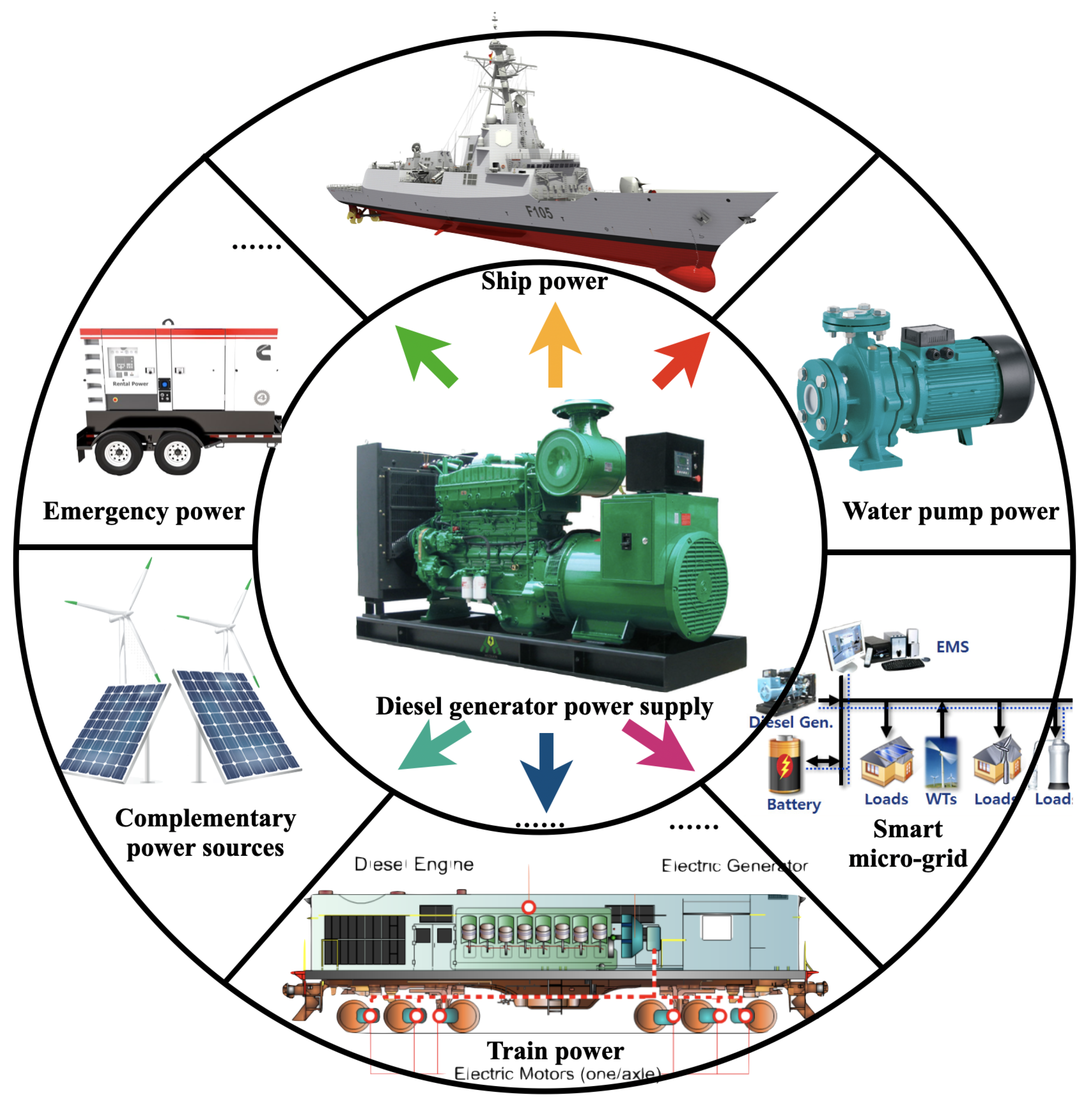
1. Introduction
- -
- Based on the theory of direct feedback linearization, a nonlinear speed and excitation robust controller of a DG is designed;
- -
- The intelligent CPSOGSA is applied to optimize the dynamic output function parameters of the robust controller, thus introducing the CPSOGSA for this problem solving multi-objective mixed robust controller;
- -
- The proposed method effectively suppresses frequency and voltage oscillations under various load disturbances and uncertainties;
- -
- Excellent damping efficiency, especially low overshoot, steady-state error, and settling time.
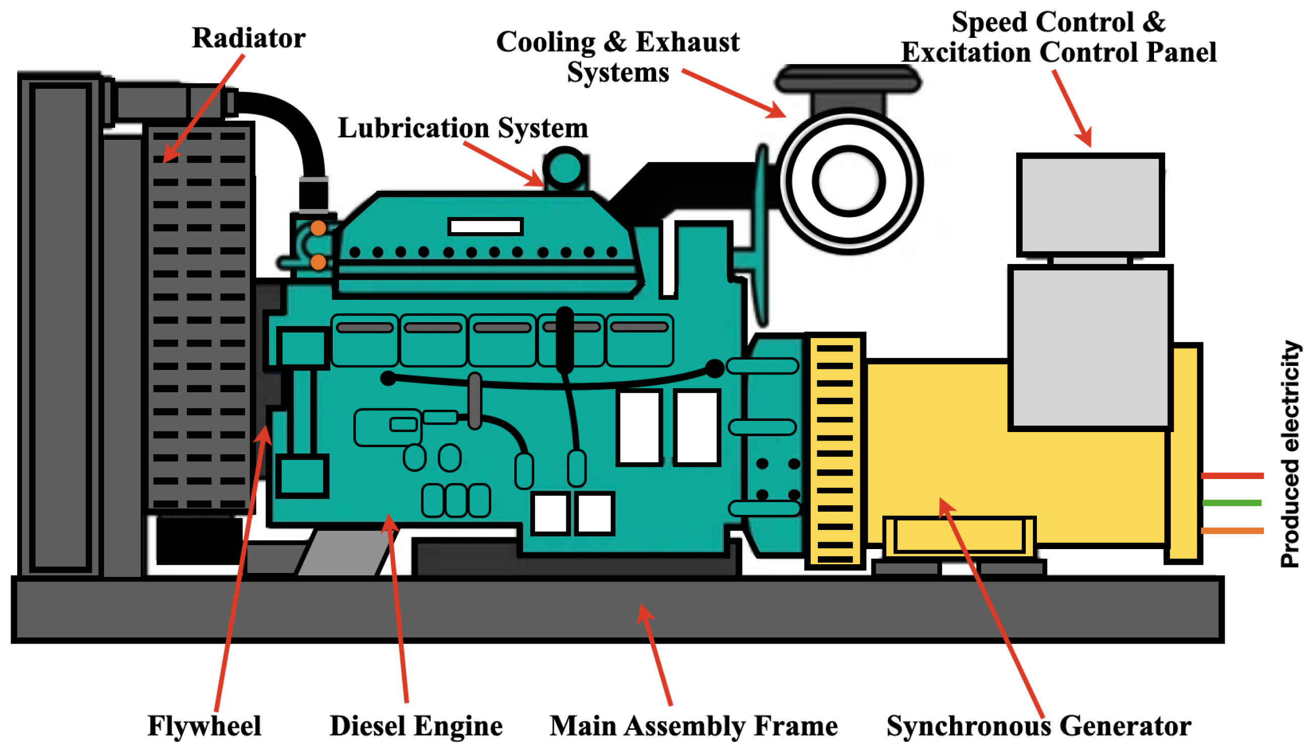
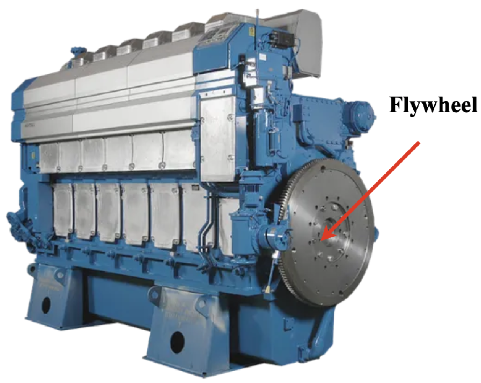
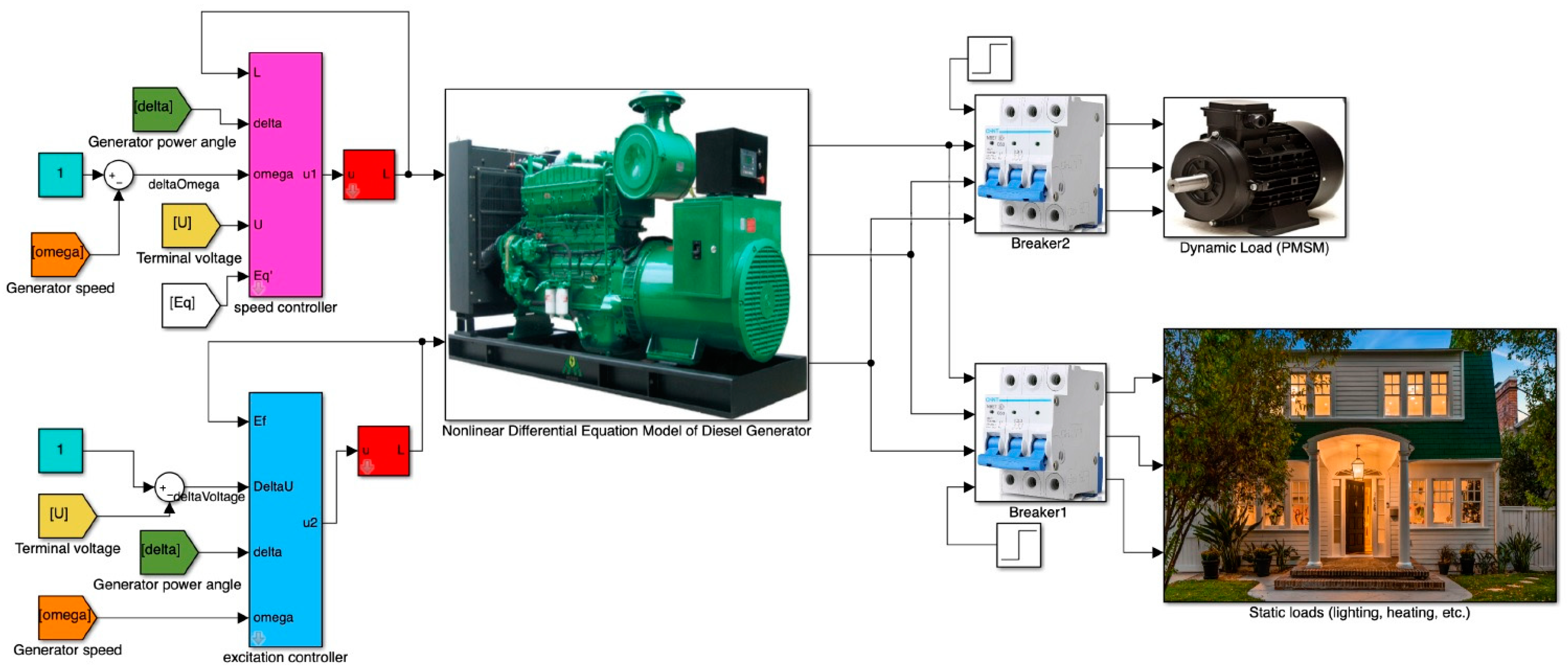
2. Modeling of Diesel Generator and Its Loads
2.1. Modeling of Speed Control Part
2.2. Modeling of Excitation Control Part
3. Design of Nonliear Synthetic Controller
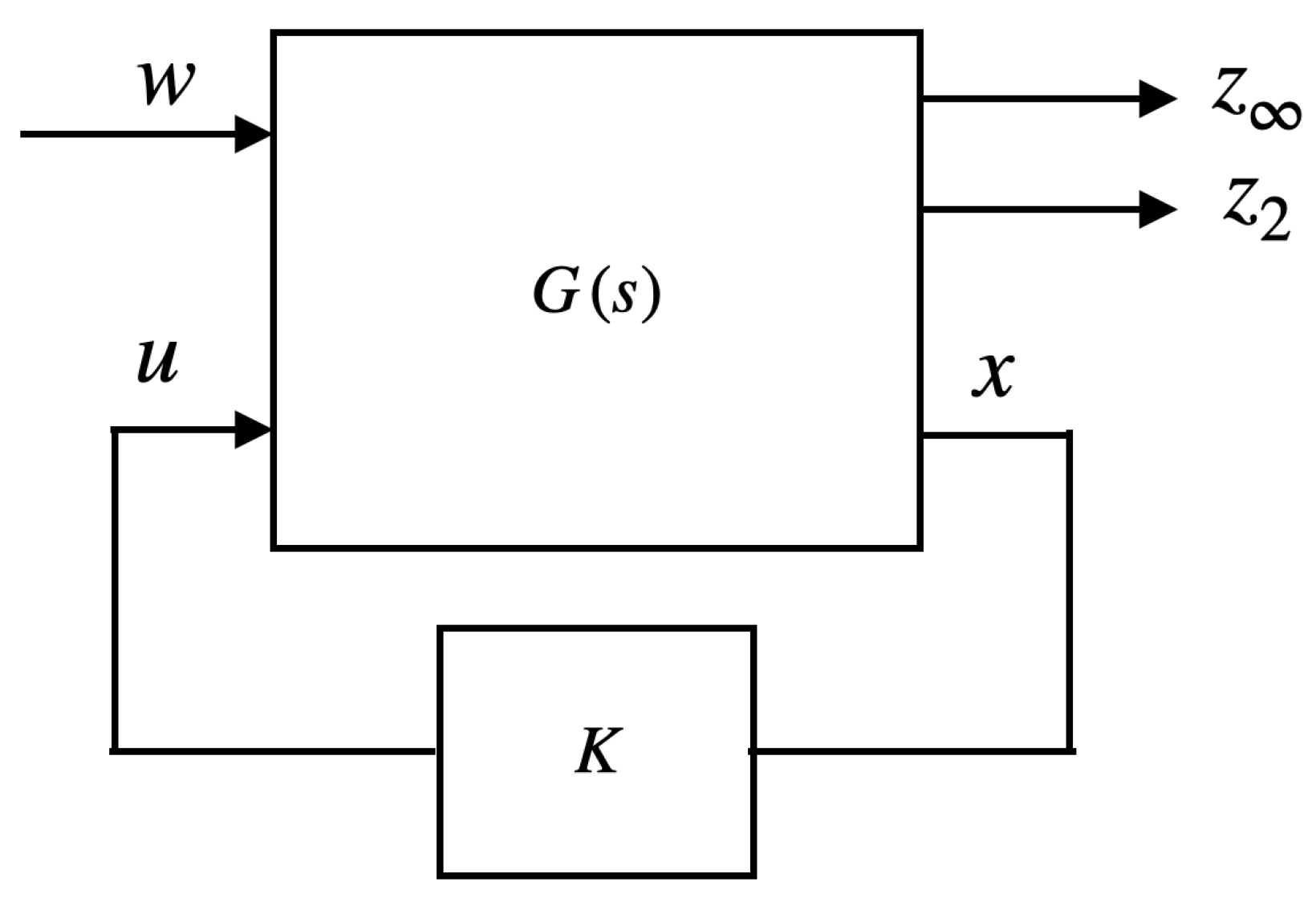
3.1. Multi-Objective State-Feedback Theory
- -
- Keep the RMS gain ( norm) of below a certain specified value ;
- -
- Maintain the norm (LQG cost) of below a certain specified value ;
- -
- Minimized the form of trade-off standard ;
- -
- Place the closed-loop pole in the designated area of the open left half-plane.
3.2. Design of Speed Controller
3.3. Design of Excitation Control Controller
4. Artificial Hybrid PSOGSA with Chaotic Maps Approach and Its Application to Multi-Objective Robust Problem
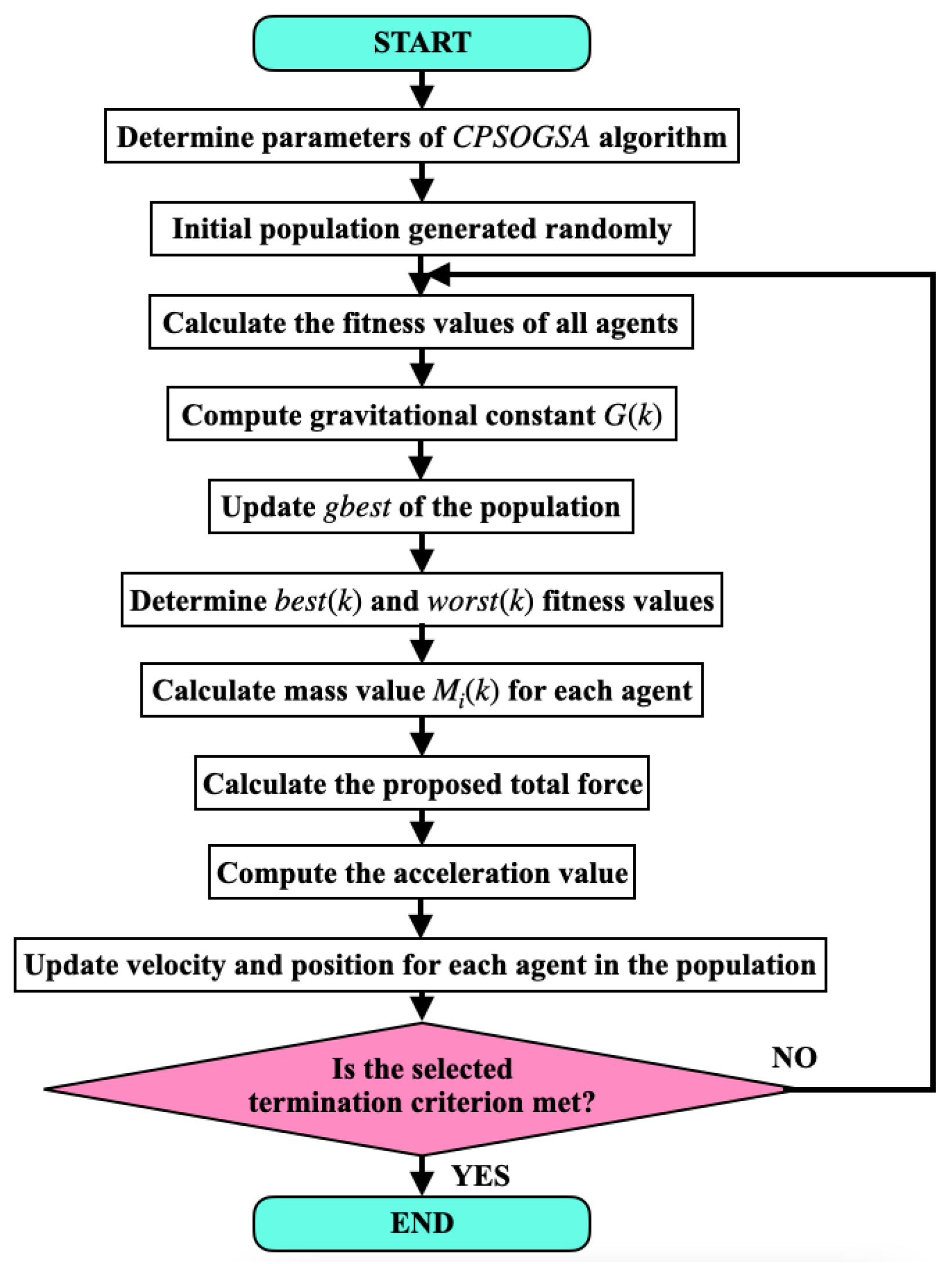
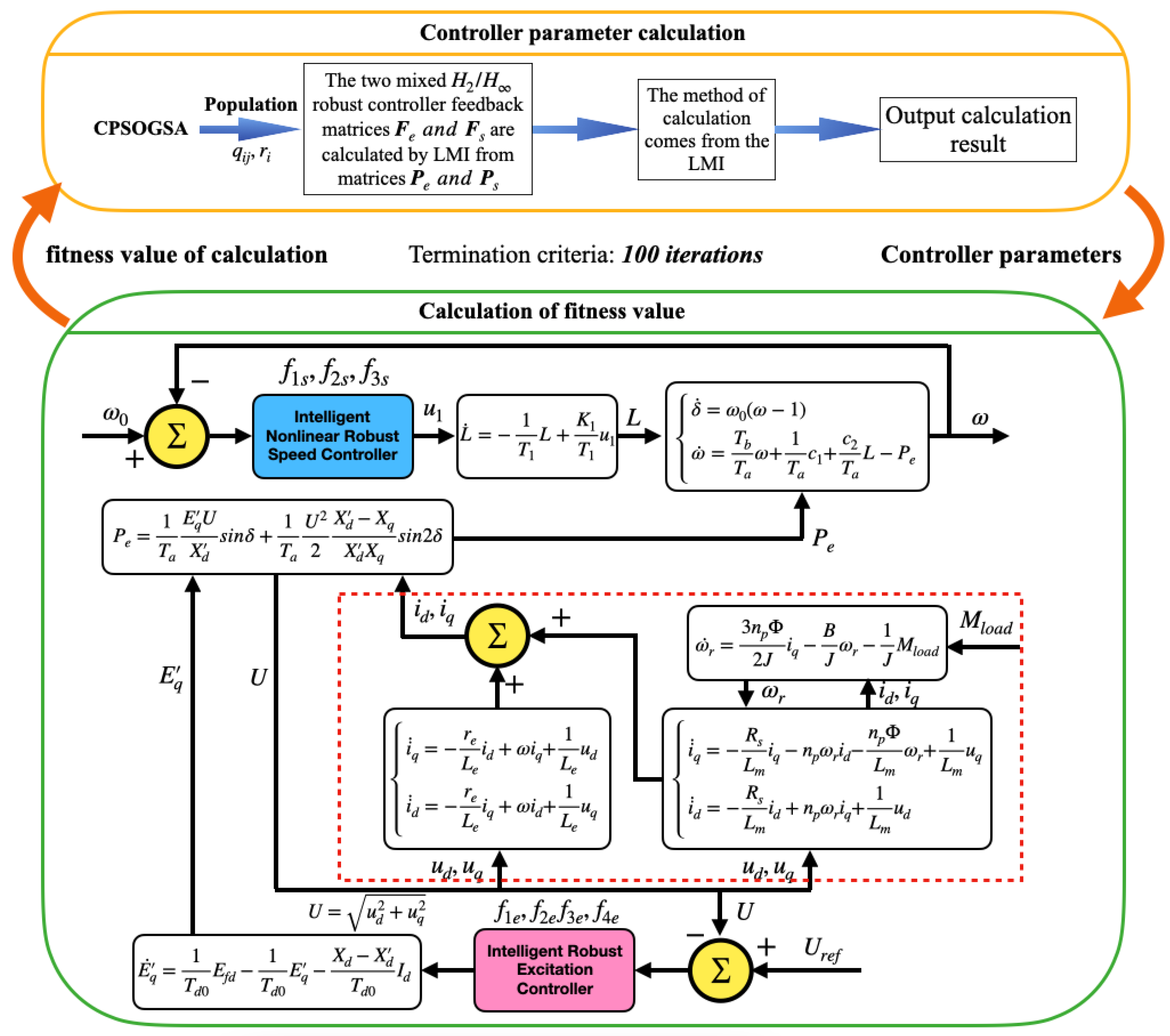
4.1. The Proposed CPSOGSA Algorithm
4.1.1. Particle Swarm Optimization
4.1.2. Gravitational Search Algorithm
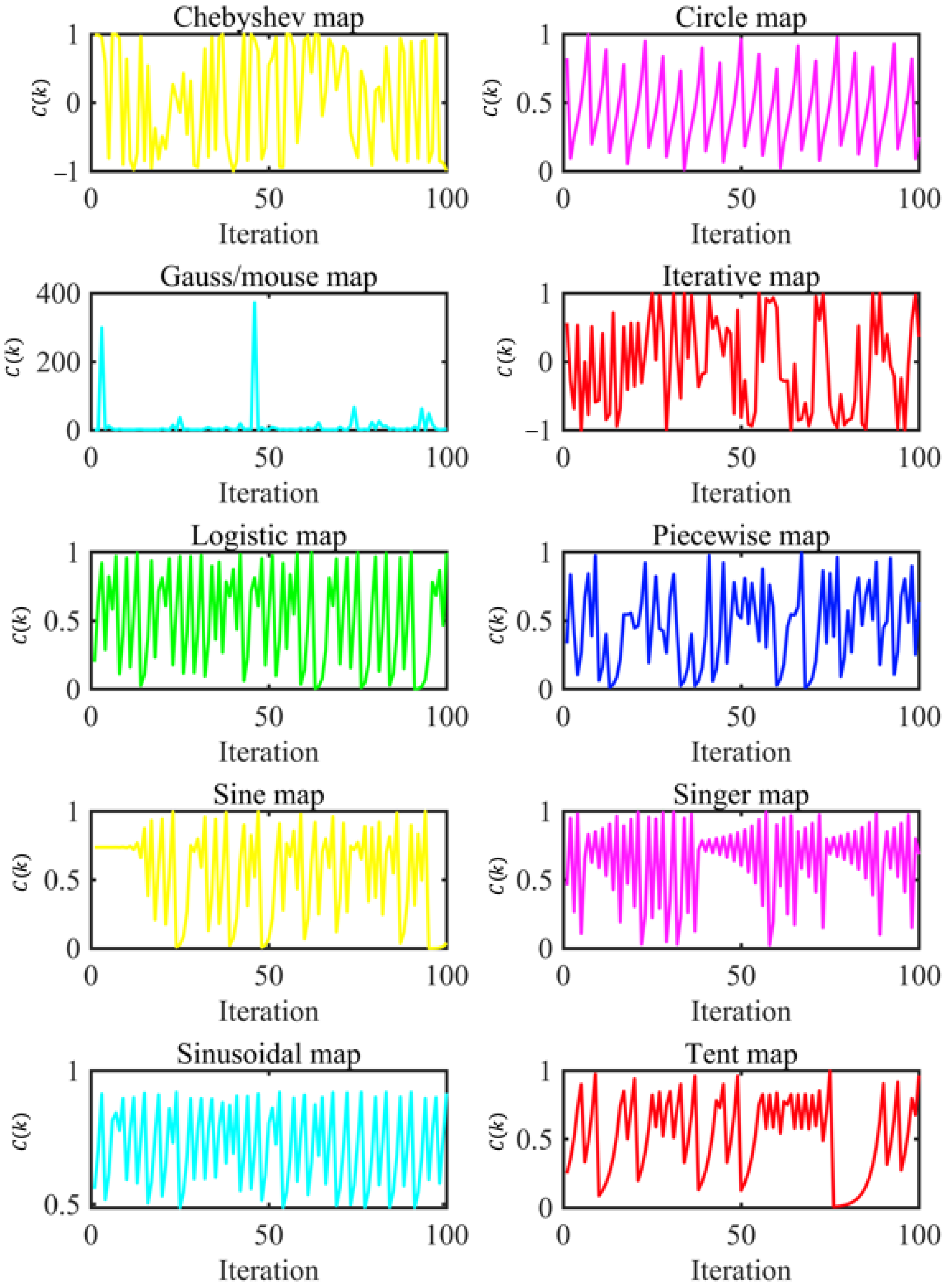
4.1.3. Modified Hybrid Particle Swarm Optimization and Gravitational Search Algorithm with Chaotic Maps
4.2. Applying CPSOGSA to Multi-Objective Robust Problem
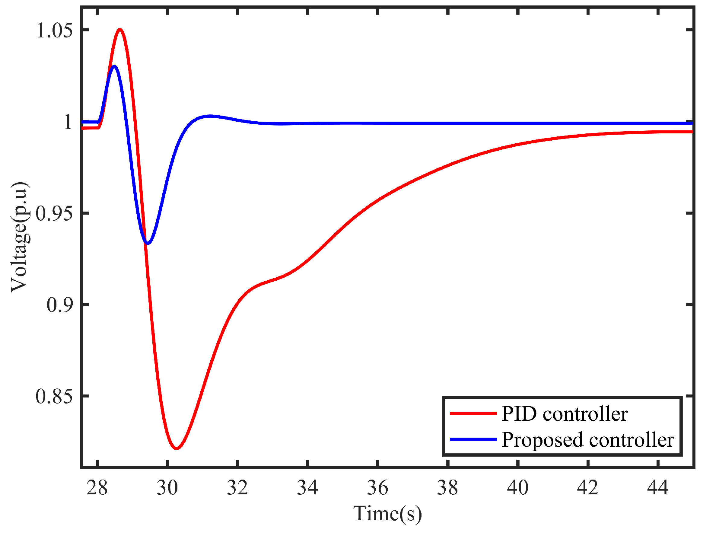
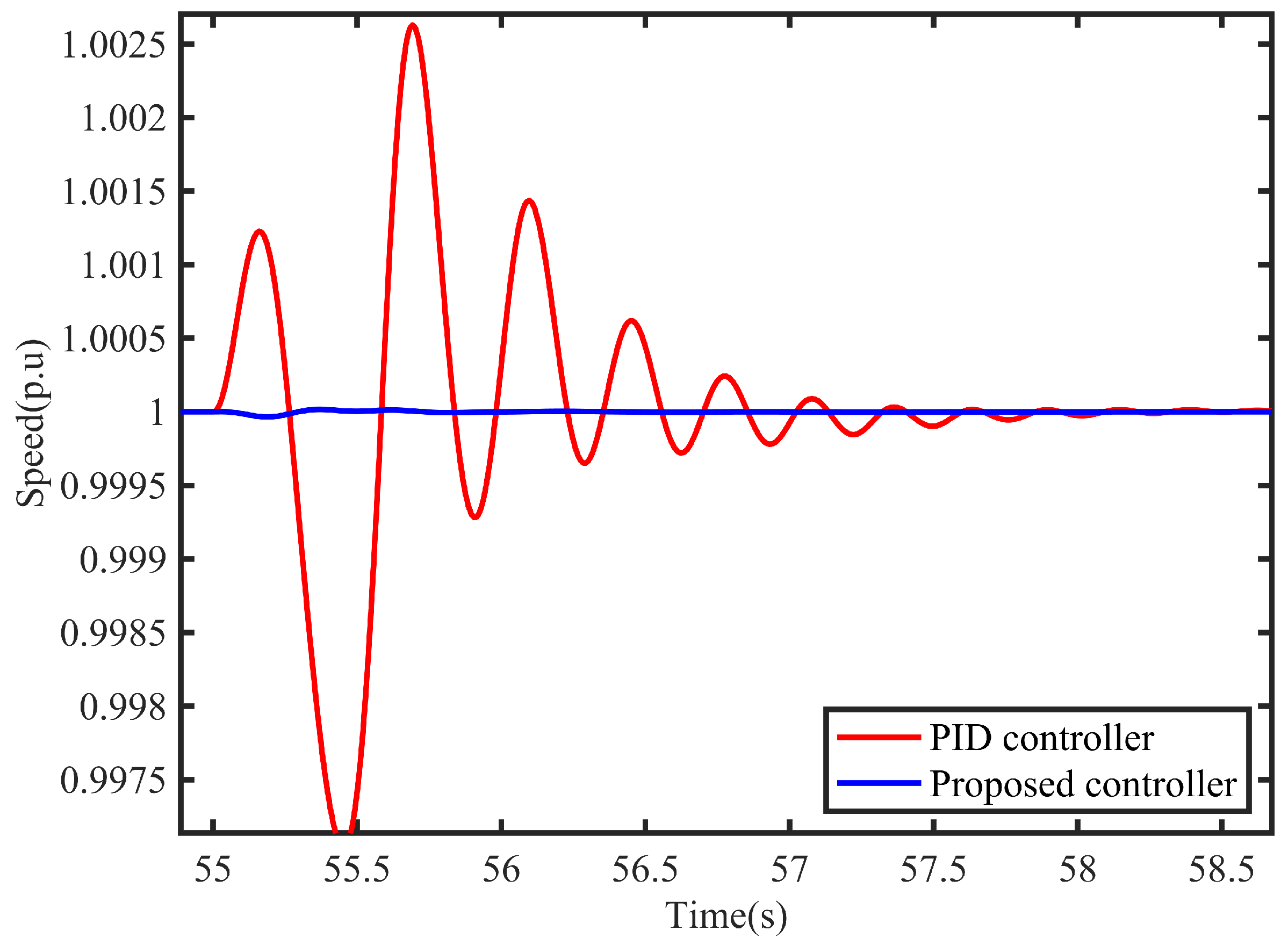
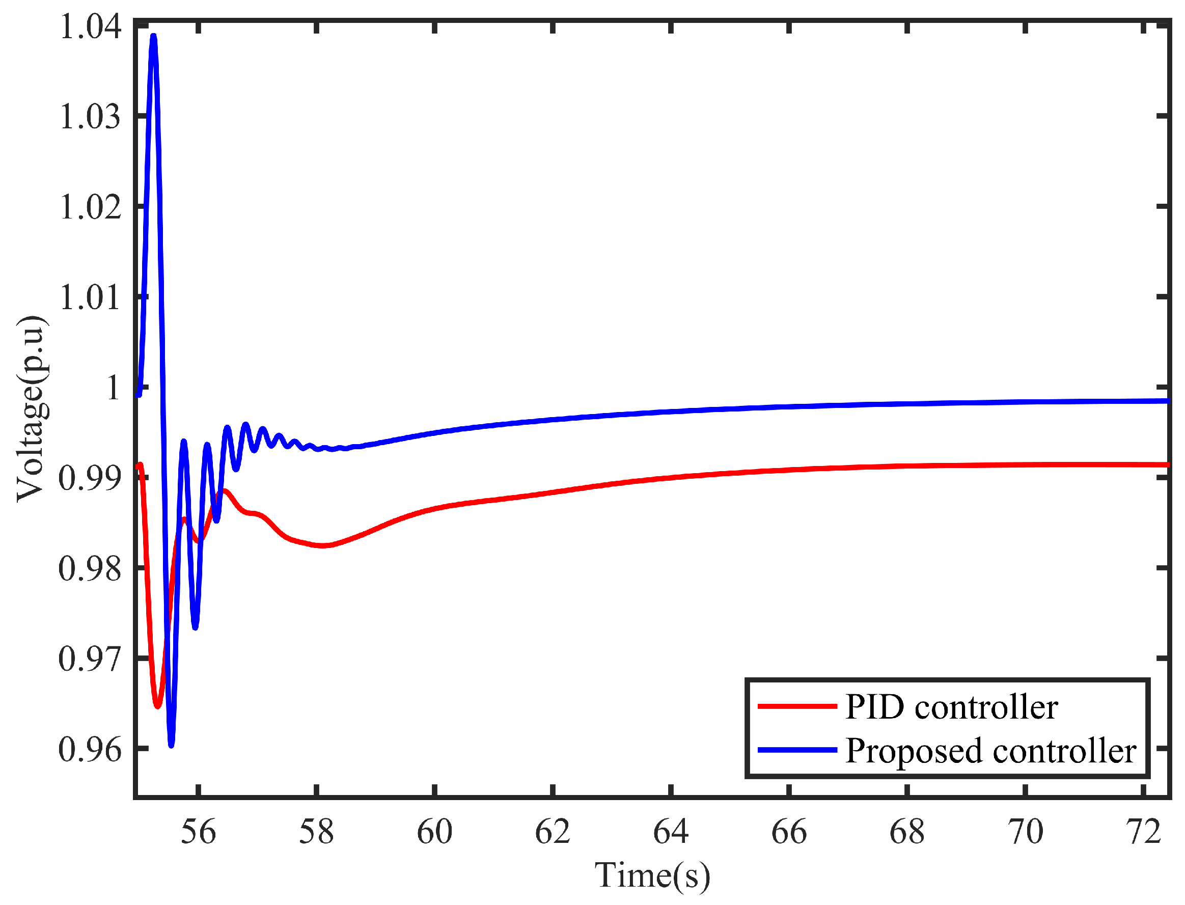
5. Numerical Study
5.1. Simulation Parameters
5.2. Simulation Results
6. Conclusions
Author Contributions
Funding
Institutional Review Board Statement
Informed Consent Statement
Data Availability Statement
Conflicts of Interest
References
- Muresan, C.I.; Birs, I.; Ionescu, C.; Dulf, E.H.; De Keyser, R. A review of recent developments in autotuning methods for fractional-order controllers. Fractal Fract. 2022, 6, 37. [Google Scholar] [CrossRef]
- Belboul, Z.; Toual, B.; Kouzou, A.; Mokrani, L.; Bensalem, A.; Kennel, R.; Abdelrahem, M. Multiobjective optimization of a hybrid PV/Wind/Battery/Diesel generator system integrated in microgrid: A case study in Djelfa, Algeria. Energies 2022, 15, 3579. [Google Scholar] [CrossRef]
- Amiryar, M.E.; Pullen, K.R. Assessment of the carbon and cost savings of a combined diesel generator, solar photovoltaic, and flywheel energy storage islanded grid system. Energies 2019, 12, 3356. [Google Scholar] [CrossRef]
- Hemeida, A.M.; Omer, A.S.; Bahaa-Eldin, A.M.; Alkhalaf, S.; Ahmed, M.; Senjyu, T.; El-Saady, G. Multi-objective multi-verse optimization of renewable energy sources-based micro-grid system: Real case. Ain Shams Eng. J. 2022, 13, 101543. [Google Scholar] [CrossRef]
- Hasankhani, A.; Hakimi, S.M. Stochastic energy management of smart microgrid with intermittent renewable energy resources in electricity market. Energy 2021, 219, 119668. [Google Scholar] [CrossRef]
- Hakimi, S.M.; Hasankhani, A.; Shafie-khah, M.; Catalão, J.P. Stochastic planning of a multi-microgrid considering integration of renewable energy resources and real-time electricity market. Appl. Energy 2021, 298, 117215. [Google Scholar] [CrossRef]
- Hu, J.; Shan, Y.; Guerrero, J.M.; Ioinovici, A.; Chan, K.W.; Rodriguez, J. Model predictive control of microgrids—An overview. Renew. Sustain. Energy Rev. 2021, 136, 110422. [Google Scholar] [CrossRef]
- Marqusee, J.; Becker, W.; Ericson, S. Resilience and economics of microgrids with PV, battery storage, and networked diesel generators. Adv. Appl. Energy 2021, 3, 100049. [Google Scholar] [CrossRef]
- Bouchekara, H.R.; Javaid, M.S.; Shaaban, Y.A.; Shahriar, M.S.; Ramli, M.A.; Latreche, Y. Decomposition based multiobjective evolutionary algorithm for PV/Wind/Diesel Hybrid Microgrid System design considering load uncertainty. Energy Rep. 2021, 7, 52–69. [Google Scholar] [CrossRef]
- Guo, Y.; Lei, X.; Wang, Q. Capacity coordination planning of isolated microgrid and battery swapping station based on the quantum behavior particle swarm optimization algorithm. Int. Trans. Electr. Energy Syst. 2021, 31, e12804. [Google Scholar] [CrossRef]
- Rameshar, V.; Sharma, G.; Bokoro, P.N.; Çelik, E. Frequency Support Studies of a Diesel–Wind Generation System Using Snake Optimizer-Oriented PID with UC and RFB. Energies 2023, 16, 3417. [Google Scholar] [CrossRef]
- Ahmed, M.; Meegahapola, L.; Vahidnia, A.; Datta, M. Stability and control aspects of microgrid architectures—A comprehensive review. IEEE Access 2020, 8, 144730–144766. [Google Scholar] [CrossRef]
- McGowan, D.J.; Morrow, D.J.; Fox, B. Multiple input governor control for a diesel generating set. IEEE Trans. Energy Convers. 2008, 23, 851–859. [Google Scholar] [CrossRef]
- Zou, Y.; Qian, J.; Zeng, Y.; Ismai, S.; Dao, F.; Feng, Z.; Nie, C.; Mei, H. Optimized Robust Controller Design Based on CPSOGSA Optimization Algorithm and H-two/H-infty Weights Distribution Method for Load Frequency Control of Micro-Grid. IEEE Access 2021, 9, 162093–162107. [Google Scholar] [CrossRef]
- Qian, J.; Guo, Y.; Zou, Y.; Yu, S. Hamiltonian Modeling and Structure Modified Control of Diesel Engine. Energies 2021, 14, 2011. [Google Scholar] [CrossRef]
- Latif, A.; Hussain, S.S.; Das, D.C.; Ustun, T.S. Double stage controller optimization for load frequency stabilization in hybrid wind-ocean wave energy based maritime microgrid system. Appl. Energy 2021, 282, 116171. [Google Scholar] [CrossRef]
- Ali, H.; Magdy, G.; Xu, D. A new optimal robust controller for frequency stability of interconnected hybrid microgrids considering non-inertia sources and uncertainties. Int. J. Electr. Power Energy Syst. 2021, 128, 106651. [Google Scholar] [CrossRef]
- Valenzuela, M.A.; Bentley, J.M.; Lorenz, R.D. Evaluation of torsional oscillations in paper machine sections. IEEE Trans. Ind. Appl. 2005, 41, 493–501. [Google Scholar] [CrossRef]
- Al-Suod MM, S.; Oleksandr, U. Optimization of the Speed Controller in Gas Diesel Device Including in the Autonomous Electric Power System. WSEAS Trans. Circuits Syst. 2019, 18, 135–140. [Google Scholar]
- Iwanski, G.; Bigorajski, Ł.; Koczara, W. Speed control with incremental algorithm of minimum fuel consumption tracking for variable speed diesel generator. Energy Convers. Manag. 2018, 161, 182–192. [Google Scholar] [CrossRef]
- Afzal Thoker, Z.; Ahmad Lone, S. Dynamic performance improvement of wind-diesel power system through robust sliding mode control of hybrid energy storage system. Wind. Eng. 2022, 46, 1065–1079. [Google Scholar] [CrossRef]
- Wang, R.; Li, X.; Ahmed, Q.; Liu, Y.; Ma, X. Speed control of a marine engine using predictive functional control based PID controller. In Proceedings of the 2018 Annual American Control Conference (ACC), Milwaukee, WI, USA, 27–29 June 2018; IEEE: Piscataway, NJ, USA, 2018; pp. 3908–3914. [Google Scholar]
- Tran, T.A. The optimization of marine diesel engine rotational speed control process by fuzzy logic control based on particle swarm optimization algorithm. Future Internet 2018, 10, 99. [Google Scholar] [CrossRef]
- Tran, T.A.; Haidara, G. A research on marine diesel engine speed controller by fuzzy logic control theory based on experimental investigation. World 2019, 17, 19. [Google Scholar] [CrossRef]
- Ding, Y.; Shi, W.; Zhang, Y.; Guo, H. Design of Neural Network Speed Controller for Marine Diesel Generator Set. Int. Core J. Eng. 2021, 7, 586–592. [Google Scholar]
- Asgari, S.; Suratgar, A.A.; Kazemi, M.G. Feedforward fractional order PID load frequency control of microgrid using harmony search algorithm. Iran. J. Sci. Technol. Trans. Electr. Eng. 2021, 45, 1369–1381. [Google Scholar] [CrossRef]
- He, Y.; Fan, A.; Wang, Z.; Liu, Y.; Mao, W. Two-phase energy efficiency optimisation for ships using parallel hybrid electric propulsion system. Ocean Eng. 2021, 238, 109733. [Google Scholar] [CrossRef]
- Li, J. Design and Application of Modern Synchronous Generator Excitation Systems; John Wiley & Sons: Hoboken, NJ, USA, 2019. [Google Scholar]
- Chakraborty, C.; Basak, S.; Rao, Y.T. Synchronous generator with embedded brushless synchronous exciter. IEEE Trans. Energy Convers. 2019, 34, 1242–1254. [Google Scholar] [CrossRef]
- Krishnamurthy, S.; Jahns, T.M.; Lasseter, R.H. The operation of diesel gensets in a CERTS microgrid. In Proceedings of the 2008 IEEE Power and Energy Society General Meeting-Conversion and Delivery of Electrical Energy in the 21st Century, Pittsburgh, PA, USA, 20–24 July 2008; IEEE: Piscataway, NJ, USA, 2008; pp. 1–8. [Google Scholar]
- Gayatri, M.T.; Parimi, A.M.; Kumar, A.P. A review of reactive power compensation techniques in microgrids. Renew. Sustain. Energy Rev. 2018, 81, 1030–1036. [Google Scholar] [CrossRef]
- Patel, R.; Hafiz, F.; Swain, A.; Ukil, A. Nonlinear excitation control of diesel generator: A command filter backstepping approach. IEEE Trans. Ind. Inform. 2020, 17, 4809–4817. [Google Scholar] [CrossRef]
- Zhao, P.; Yao, W.; Wen, J.; Jiang, L.; Wang, S.; Cheng, S. Improved synergetic excitation control for transient stability enhancement and voltage regulation of power systems. Int. J. Electr. Power Energy Syst. 2015, 68, 44–51. [Google Scholar] [CrossRef]
- Ramakrishnan, K. Delay-dependent stability of networked generator-excitation control systems: An LMI based approach. IFAC-PapersOnLine 2016, 49, 431–436. [Google Scholar] [CrossRef]
- Berkoune, K.; Sedrine, E.B.; Vido, L.; Le Ballois, S. Robust control of hybrid excitation synchronous generator for wind applications. Math. Comput. Simul. 2017, 131, 55–75. [Google Scholar] [CrossRef]
- Pramanik, M.A.; Roy, T.K.; Ghosh, S.K.; Anower, M.S.; Mahmud, M.A. Robust partial feedback linearizing excitation controller design for higher-order synchronous generator in smib systems to improve the transient stability. In Proceedings of the 2021 IEEE Texas Power and Energy Conference (TPEC), College Station, TX, USA, 2–5 February 2021; IEEE: Piscataway, NJ, USA, 2021; pp. 1–6. [Google Scholar]
- Orchi, T.F.; Roy, T.K.; Mahmud, M.A.; Oo, A.M. Feedback linearizing model predictive excitation controller design for multimachine power systems. IEEE Access 2017, 6, 2310–2319. [Google Scholar] [CrossRef]
- Roy, T.K.; Mahmud, M.A.; Shen, W.; Oo, A.M.; Haque, M.E. Robust nonlinear adaptive backstepping excitation controller design for rejecting external disturbances in multimachine power systems. Int. J. Electr. Power Energy Syst. 2017, 84, 76–86. [Google Scholar] [CrossRef]
- Mobarra, M.; Rezkallah, M.; Ilinca, A. Variable speed diesel generators: Performance and characteristic comparison. Energies 2022, 15, 592. [Google Scholar] [CrossRef]
- Mobarra, M.; Tremblay, B.; Rezkallah, M.; Ilinca, A. Advanced control of a compensator motor driving a variable speed diesel generator with rotating stator. Energies 2020, 13, 2224. [Google Scholar] [CrossRef]
- Huang, M.L.; Song, K.M.; Wei, Z.D. Nonlinear H-two/H-infinity synthetic controller for diesel-generator set. Control Theory Appl. 2011, 28, 885–893. [Google Scholar]
- Issa, M.; Ibrahim, H.; Lepage, R.; Ilinca, A. A review and comparison on recent optimization methodologies for diesel engines and diesel power generators. J. Power Energy Eng. 2019, 7, 31. [Google Scholar] [CrossRef]
- Ramstedt, M. Cylinder-by-Cylinder Diesel Engine Modelling: A Torque-Based Approach. Master’s Thesis, Linköping University, Linkoping, Sweden, 2004. [Google Scholar]
- Zhang, Y.; Zhang, X.; Qian, T.; Hu, R. Modeling and simulation of a passive variable inertia flywheel for diesel generator. Energy Rep. 2020, 6, 58–68. [Google Scholar] [CrossRef]
- Huang, M.; Wang, C. Nonlinear mathematical model of diesel generator sets in marine power stations. J. Harbin Eng. Univ. 2006, 27, 15–19. [Google Scholar]
- Huang, M.L.; Wei, Z.D.; Song, K.M. Synchronous generator state feedback H-infty regulator for marine power plants. J. Power Syst. Autom. 2011, 23, 15–20. [Google Scholar]
- Huang, M.; Wang, C. Simulation study of H-infty governor for diesel engines in marine power stations. J. Electr. Eng. Technol. 2006, 10, 125–129. [Google Scholar]
- Zou, Y.; Hu, W.; Xiao, Z.; Wang, Y.; Chen, J.; Zheng, Y.; Qian, J.; Zeng, Y. Design of intelligent nonlinear robust controller for hydro-turbine governing system based on state-dynamic-measurement hybrid feedback linearization method. Renew. Energy 2023, in press.
- Dao, F.; Zou, Y.; Zeng, Y.; Qian, J.; Li, X. An intelligent CPSOGSA-based mixed H-two/H-infty robust controller for the multi-hydro-turbine governing system with sharing common penstock. Renew. Energy 2023, in press.
- Li, L.; Qian, J.; Zou, Y.; Tian, D.; Zeng, Y.; Cao, F.; Li, X. Optimized Takagi–Sugeno Fuzzy Mixed H-two/H-infty Robust Controller Design Based on CPSOGSA Optimization Algorithm for Hydraulic Turbine Governing System. Energies 2022, 15, 4771. [Google Scholar] [CrossRef]
- Duman, S.; Li, J.; Wu, L.; Guvenc, U. Optimal power flow with stochastic wind power and FACTS devices: A modified hybrid PSOGSA with chaotic maps approach. Neural Comput. Appl. 2020, 32, 8463–8492. [Google Scholar] [CrossRef]
- Rather, S.A.; Bala, P.S. Constriction coefficient based particle swarm optimization and gravitational search algorithm for multilevel image thresholding. Expert Syst. 2021, 38, e12717. [Google Scholar] [CrossRef]
- Rather, S.A.; Bala, P.S. A hybrid constriction coefficient-based particle swarm optimization and gravitational search algorithm for training multi-layer perceptron. Int. J. Intell. Comput. Cybern. 2020, 13, 129–165. [Google Scholar] [CrossRef]
- Xie, S.; Zeng, Y.; Qian, J.; Yang, F.; Li, Y. CPSOGSA Optimization Algorithm Driven Cascaded 3DOF-FOPID-FOPI Controller for Load Frequency Control of DFIG-Containing Interconnected Power System. Energies 2023, 16, 1364. [Google Scholar] [CrossRef]
- Rather, S.A.; Bala, P.S. Hybridization of constriction coefficient-based particle swarm optimization and chaotic gravitational search algorithm for solving engineering design problems. In Applied Soft Computing and Communication Networks: Proceedings of ACN 2019; Springer: Singapore, 2020; pp. 95–115. [Google Scholar]


| 1.136 | −0.492 | 1.515 | −0.215 | 2.053 | 0.213 |
| R | |||||
| 1.003 | 0.050 | 0.011 | 2.200 | 0.200 | 0.1 |
Disclaimer/Publisher’s Note: The statements, opinions and data contained in all publications are solely those of the individual author(s) and contributor(s) and not of MDPI and/or the editor(s). MDPI and/or the editor(s) disclaim responsibility for any injury to people or property resulting from any ideas, methods, instructions or products referred to in the content. |
© 2023 by the authors. Licensee MDPI, Basel, Switzerland. This article is an open access article distributed under the terms and conditions of the Creative Commons Attribution (CC BY) license (https://creativecommons.org/licenses/by/4.0/).
Share and Cite
Zou, Y.; Xiao, B.; Qian, J.; Xiao, Z. Design of Intelligent Nonlinear H2/H∞ Robust Control Strategy of Diesel Generator-Based CPSOGSA Optimization Algorithm. Processes 2023, 11, 1867. https://doi.org/10.3390/pr11071867
Zou Y, Xiao B, Qian J, Xiao Z. Design of Intelligent Nonlinear H2/H∞ Robust Control Strategy of Diesel Generator-Based CPSOGSA Optimization Algorithm. Processes. 2023; 11(7):1867. https://doi.org/10.3390/pr11071867
Chicago/Turabian StyleZou, Yidong, Boyi Xiao, Jing Qian, and Zhihuai Xiao. 2023. "Design of Intelligent Nonlinear H2/H∞ Robust Control Strategy of Diesel Generator-Based CPSOGSA Optimization Algorithm" Processes 11, no. 7: 1867. https://doi.org/10.3390/pr11071867
APA StyleZou, Y., Xiao, B., Qian, J., & Xiao, Z. (2023). Design of Intelligent Nonlinear H2/H∞ Robust Control Strategy of Diesel Generator-Based CPSOGSA Optimization Algorithm. Processes, 11(7), 1867. https://doi.org/10.3390/pr11071867