1. Introduction
Wave energy is a renewable energy source that has gained significant global research interest due to its high energy density and potential [
1]. However, the commercialization of wave energy converter technology is still challenging due to its high unit cost (levelized cost of electricity, LCOE) of energy compared to other renewable energy sources [
2]. Various studies have been conducted to address this issue [
3,
4,
5].
Most wave energy converters are designed to operate at resonance with the incident waves, maximizing the energy extraction based on the natural frequency of the system [
6]. Oscillating-water-column (OWC) devices and movable-body-type devices are two major types of wave energy converters designed for resonance. OWC devices, which operate by compressing and expanding air without direct contact with the waves, have shown stability and are closest to commercialization [
7,
8,
9]. Control algorithms play a crucial role in improving the performance and commercial viability of OWC devices. The maximum power point tracking (MPPT) algorithm is important for obtaining the maximum output based on the input wave energy [
10,
11,
12]. Additionally, rated power control, which enables the system to respond to wave variability, is essential [
13,
14,
15,
16]. However, the optimal rated power control technology to overcome wave energy variability is yet to be developed [
17,
18,
19,
20,
21].
In order to overcome the challenges posed by wave variability, several studies have proposed the use of artificial intelligence (AI)-based deep learning techniques in renewable energy applications [
22,
23,
24,
25,
26]. Asrari et al. [
22] proposed a method for predicting the hourly sunshine state for photovoltaic power generation; Mendonça de Paiva et al. [
23] conducted a study on the improvement of wind speed estimation performance for wind turbine systems; and Roh [
27] conducted a study on large-scale wind turbine control. Ju et al. [
28] investigated an operation control algorithm to predict the generation output of renewable energy and increase the economic feasibility. In conclusion, as artificial-intelligence-based estimation techniques are being introduced in various renewable energy fields, estimation control algorithms based on artificial intelligence technology are expected to be able to control the variability of wave energy more precisely. However, despite the extreme variability in wave power generation, AI-based control applications are found lacking [
20]. Roh and Kim [
20] analyzed the angular velocity estimation performance of the wave power generator according to a deep learning algorithm; however, they did not evaluate the applicability of the actual control system. There may be a limit to accurately determining the operating characteristics of an actual system. That is, it is necessary to develop a control algorithm capable of confirming the dynamic characteristics of the actual system under the input conditions of the wave power generator and to verify its performance.
In this study, a deep learning model that can predict the valve control angle based on various operating data of the target model was constructed to perform stable rated power control overcoming the inevitable time delay that may occur in real systems. Through this, this paper evaluated the performance of the rating control algorithm that predicts the valve control angle in advance based on input data that change in real time. The proposed method can expand the operating range of the wave energy converter by increasing the generation time, as well as the stability of the system, by stably controlling the energy that rapidly changes in seconds. The proposed rating controller was compared with an ideal rated controller without time delay and a rated controller with time delay reflecting the characteristics of the actual system. To this end, the amount of power generated, the change in angular velocity, and the control angle of each rated controller were analyzed. In conclusion, the proposed method compensates for the time delay that inevitably occurs in the actual system by predicting the valve control angle through a deep learning algorithm. Through this, stable power generation and an increased system operation rate could be achieved.
The rest of this paper is structured as follows.
Section 2 presents the control algorithm and the problems of the existing frequency columnar wave generator—the time delay of the behavior actuator and the amount of change in current generation based on the target model.
Section 3 describes the proposed deep-learning-based algorithm. It includes the deep learning algorithm construction method and verification through the target model.
Section 4 compares the performance with the existing method under the rated control operation condition and the proposed condition. Finally,
Section 5 presents the conclusion and the direction of contribution of this study. It also presents research directions and utilization plans based on various analyses.
2. Conventional Control Methods and Problems of OWC-WECs
The oscillating water column–type wave energy converter utilizes irregular wave energy to produce the electrical energy required by the power system. Wave energy has a great deal of potential energy globally, but it is still in the developmental stages. At present, oscillating-water-column wave energy converters are considered the closest model to commercialization in terms of stability and maintenance.
Oscillating-water-column wave energy converters consist of a chamber, a turbine, a generator, and a power converter. The chamber converts wave energy into pneumatic energy; the turbine converts pneumatic energy into mechanical energy; and the generator and power converters convert the mechanical energy into electrical energy.
As with all renewable energies, the input energy of the oscillating-water-column wave energy converter has high variability; therefore, the amount of power generated must be adjusted through appropriate control. In other words, an optimal control technology is required to extract the maximum amount of power generation in response to the variability of the input energy and to overcome the energy above the rated value. In particular, because the variability of wave energy has a large peak-to-average ratio, control is difficult, and moreover, inappropriate control reduces power generation and utilization.
Figure 1 shows the load control curves of oscillating-water-column wave energy converters. The load control curve can be derived from the power takeoff (PTO) of the oscillating-water-column wave energy converters [
17]. The PTO consists of a turbine, a generator, and a power converter. The efficiency of the turbine has a dominant effect; therefore, the load control curve was derived based on the performance curve of the turbine. The turbine used in this study is an impulse turbine, and the operation model can be expressed as follows, based on the steady-state and one-way flow models.
The control of the OWC-WECs can be divided into three regions according to the input energy [
14]. Region 1 is a region in which the generation load does not operate because of low input energy and there is no power generated. In region 2, a generation load is applied to obtain the maximum generated power according to the input energy. In region 2, an angular-velocity-based generation load was applied according to the change in the input energy. Region 3 controls the input energy entering the turbine through the valve because more energy than the system can handle enters owing to the large amount of input energy.
In region 2, the load control curve analysis of the PTO system of the oscillating-column wave power generator can represent the turbine-side flow velocity as an input condition. Based on Equation (1), the input power can be calculated as follows:
Based on the input power (
) and turbine efficiency (
) shown in Equation (3), the mechanical power (
) can be calculated as follows:
The standard load value for obtaining maximum power generation was obtained when all the mechanical power was converted into electrical power. Assuming that the reference load value is equal to the mechanical torque, it can be calculated as follows:
Based on Equation (6), the reference current value for electrical load control can be calculated as follows based on the generator constant value:
where
represents the number of poles of the generator and
represents the flux linkage of the generator.
Rating control was performed by reducing the input energy by operating the valve at an angular velocity above the rating in
Section 3. The rated control can create a control signal based on the rated angular velocity and the current angular velocity.
Figure 2 shows a block diagram of the rated power control system.
Because the variability of the input energy of oscillating-water-column wave converters is large, an inaccurately rated power controller reduces the utilization rate of the system. However, a rated power controller using a mechanical device may cause a time delay in the mechanical operation [
20]. That is, even when an operating signal is received, the actual operating time of the system is delayed. Because the wave energy changes significantly in a few seconds, the control delay represents an inaccurate rated power control.
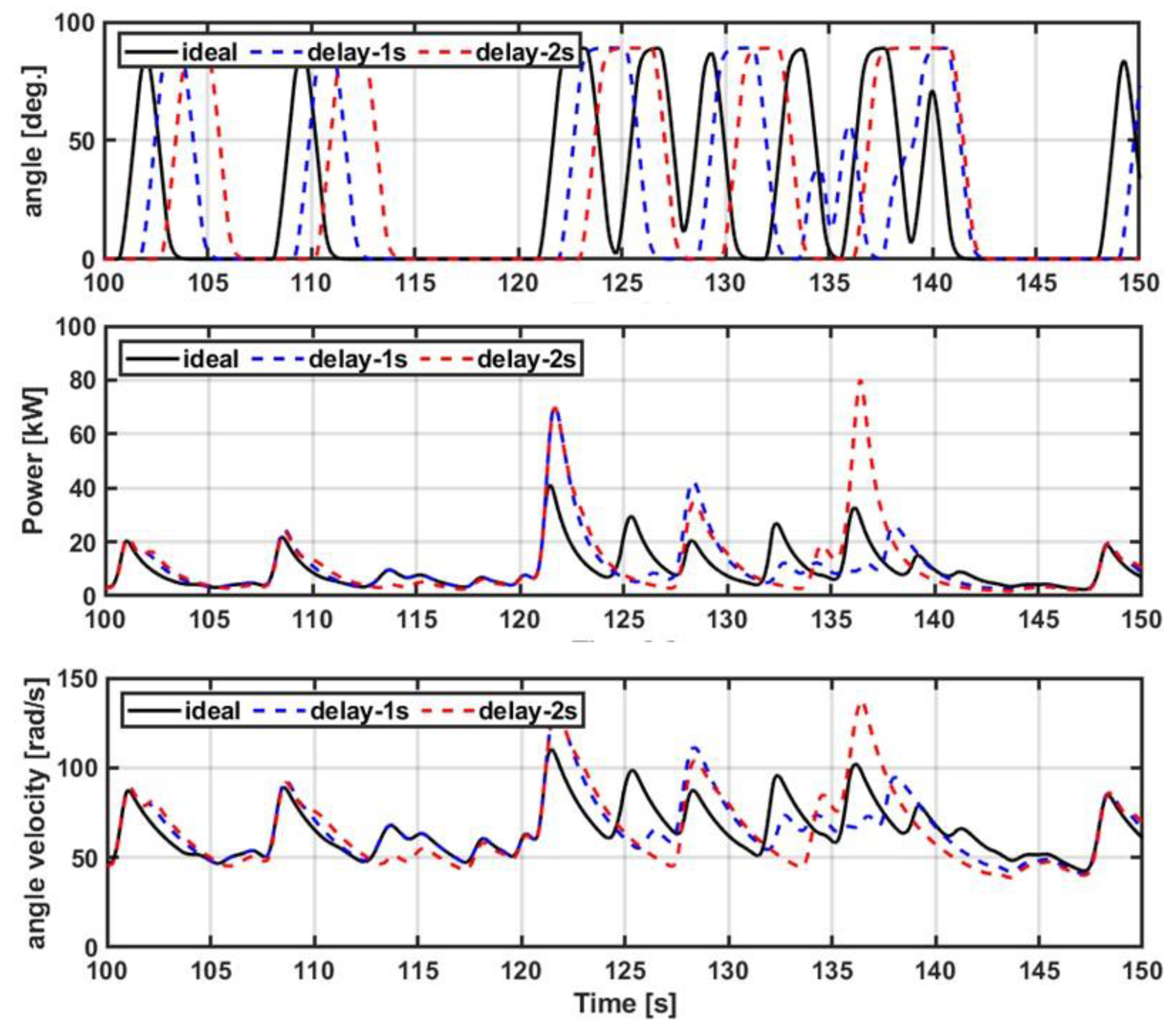
Figure 3 shows the characteristics of the rated controller according to the time delay. The valve control angle represents the system characteristics with a time delay of 1 s and 2 s to reflect the time delay of the ideal controller and the actual system. Time delays of 1 s and 2 s were used to check the effect on the system as the delay time increases, and the target model had a 2 s time delay. When the time delay occurs, the electrical output and the turbine angular velocity exceed the rated value, and the 2 s time delay, similar to that in an actual system, results in more than twice the rated power.
3. Proposed Algorithm Based on Deep Learning
Deep learning algorithms have already been applied to data estimation in many industries. In particular, owing to the nature of renewable energy with irregular input energy and high variability, estimation technology using deep learning algorithms is not only necessary but also actively researched. Estimation technology configures an algorithm that considers various input variables, and the accuracy of the estimation may also change according to the data combination and accuracy. Therefore, in this study, we propose a predictive control method based on a deep learning algorithm to compensate for the time delay caused by mechanical motion. Through this, it is possible to compensate for the decrease in the operation rate and the amount of power generation of the OWC-WECs caused by the mechanical delay. We analyzed the input data affecting the time delay to analyze and compensate for the mechanical delay and configured an algorithm that can predict the mechanical delay time.
Figure 4 shows the configuration of the proposed algorithm, which can compensate for the time delay based on a deep learning algorithm. The proposed algorithm performs predictive control to compensate for the mechanical operation delay time of the valve-driven actuator to implement the rated control. Time delay compensation predicts the valve motion control signal using a deep learning algorithm. The mechanical operation delay is compensated for by estimating the valve angle, in advance, by the delay time. Through this, it is possible to obtain an increase in the operation rate and increase the power generation of the vibration-column-type wave power generator.
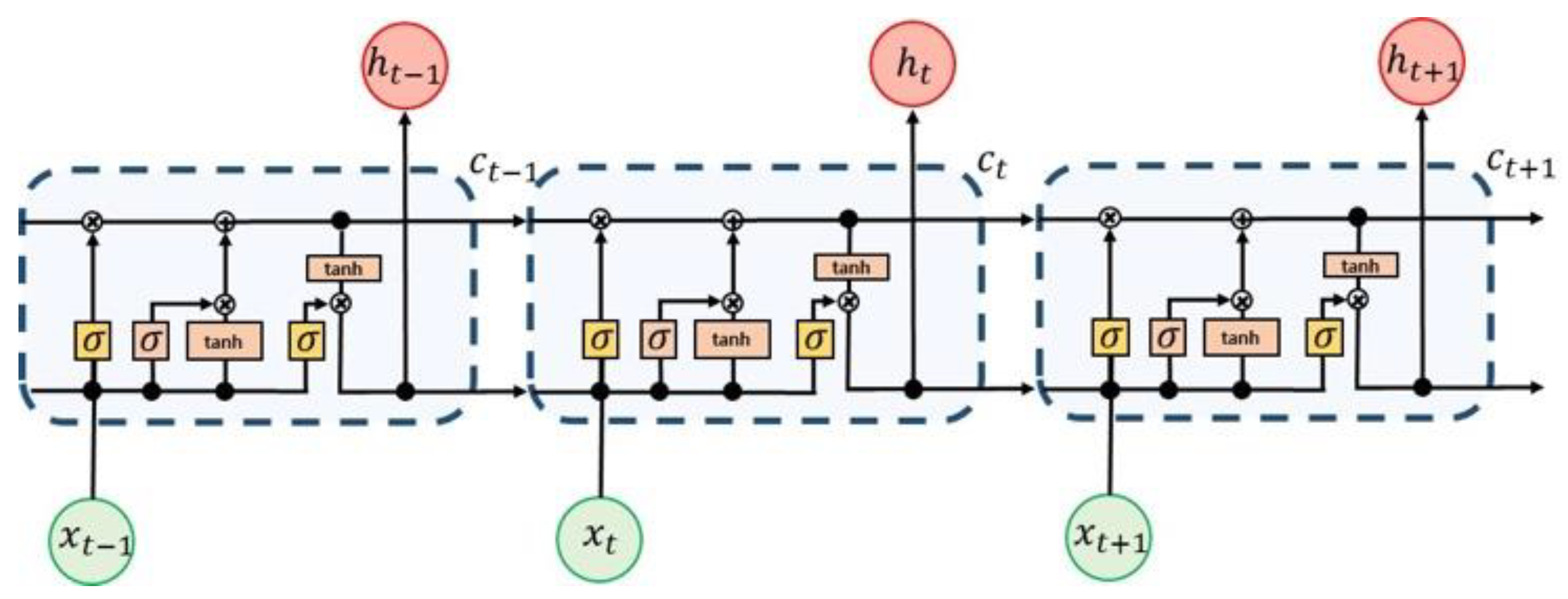
The deep learning algorithm applied in this study used long short-term memory (LSTM). As shown in [
20], this is the most accurate valve-angle estimation method. The LSTM algorithm is suitable for predicting time algorithms because the back propagation gradient has high propagation based on the forget and input gates.
Figure 5 shows a block diagram of the LSTM algorithm.
The past input information was selected in the forget gate. A value between 0 and 1 was used to properly reflect the past state information using the sigmoid function: if the value was 0, the information from the previous state was forgotten, and if the value was 1, the information from the previous state was fully remembered. The gate of oblivion can be represented as [
29]
The input gate stores the current input data. Using the hidden state value (
ht−1) from the previous step and the current state data, we can calculate the strength and direction of the current data as
The LSTM equations reflecting the forget gate and the input gate can be written as
Figure 6 shows the correlation of the input data to configure the rating control based on the deep learning algorithm. The correlation matrix confirmed the predictive performance of the data. Thus, it is possible to select the input data that affect the estimation data. The numbers and colors shown in
Figure 6 indicate the degree of correlation. The closer the number is to 1, the closer the color is to white and the higher the degree of correlation. The input is the amount of electricity generation (power), the angular velocity (speed), and the current valve angle (ang), and the output is the valve control angle after 2 s (pre_ang).
In this study, to compensate for the physical time delay, the valve angle of the rated control was predicted in advance by the time delay. A physical time delay of 2 s was predicted for the predicted time. The input data for the valve angle estimation consist of the electrical power, turbine angular velocity, and current valve angle. The input data were acquired by constructing an OWC simulation experiment set, and a comparison was performed with the actual sea area experiment data. As training data, 18 h of data from an ideal rated controller under various wave conditions (Hs = 0.5~2 m, Tp = 4~8 s) were used. The amount of data for one hour was 360,000 data points, and the training time for one hour of data was approximately 6 h. For the training data, 80% of the total data were randomly learned, and the remaining 20% were used as verification data. The loss model of the deep learning model uses the mean squared error (MSE), which is the most common loss model.
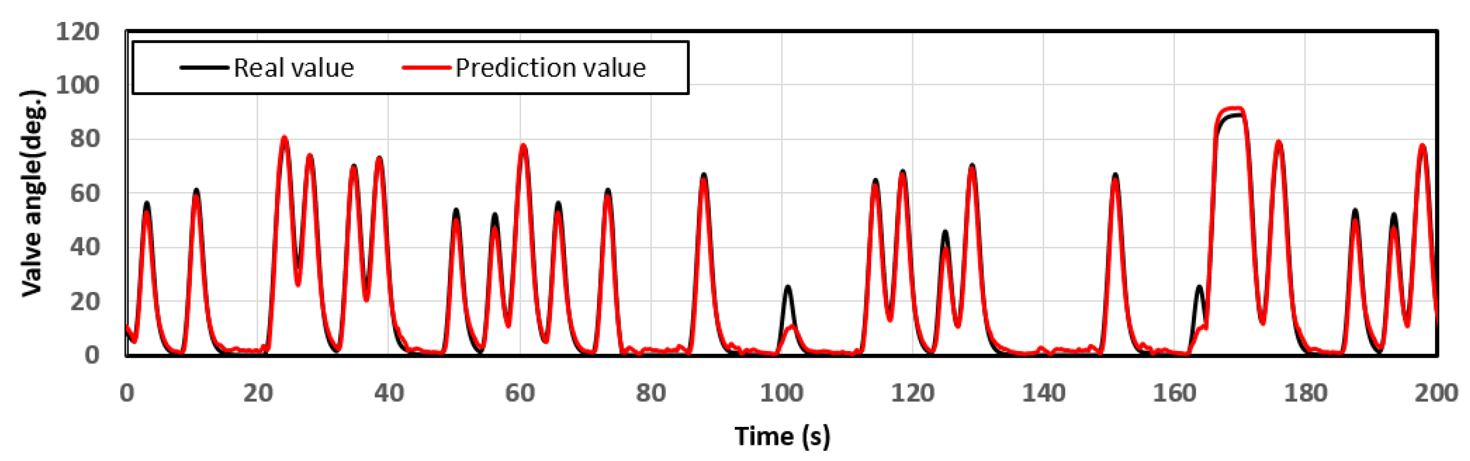
Figure 7 shows the actual valve angle after 2 s for the rated power control and the valve angle predicted using the deep learning algorithm. It can be confirmed that the proposed deep learning algorithm–based rating control method appropriately followed the actual valve control angle after 2 s. In other words, the proposed method can compensate for the time delay by predicting in advance, even though a physical time delay occurs. The valve angle MSE for that model was approximately 0.5592.
The dynamic analysis of the vibrating-column wave power generator was performed using the vibrating-column wave power model presented in [
20].
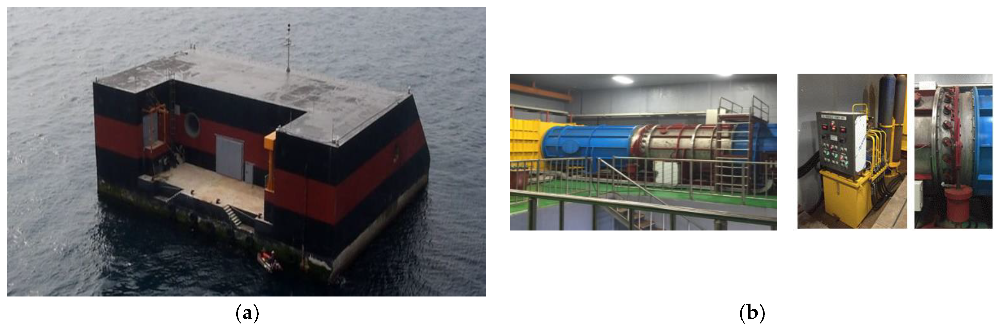
Figure 8 illustrates the application of a deep learning model in this study, which was trained using real sea operation data. Additionally, a time-delay hydraulic device was developed based on the actuator shown in
Figure 8b. The dynamic analysis model was implemented using MATLAB/Simulink, and a comparative verification was conducted by comparing it with the model presented in [
20]. The numerical analysis compared three controller configurations: an ideal rated controller (referred to as “Conv”), a rated controller considering physical time delay (referred to as “delay”), and a deep learning algorithm–based rated controller (referred to as “proposed”). To provide a visual representation,
Figure 9 displays the configuration models of the deep learning algorithm for the proposed method and the configuration diagram of the method applied in this study. The MATLAB/Simulink model was developed based on the configuration shown in
Figure 9 [
21].
4. Results and Discussion
The performance of the oscillating-water-column wave energy converters was evaluated using different rated controllers under assumed environmental input conditions. The ideal rated controller (“Conv”) accurately calculated the valve angle without any time delay. The rated controller with a time delay (“delay”) reflected the same physical time delay as the actual system, with a 2 s delay in the calculated valve control angle. The proposed rated controller (“prop”) predicted the valve control angle 2 s in advance, allowing it to operate smoothly even in the presence of a physical time delay, with the predicted angle being implemented 2 s earlier to offset the time delay.
The system was rated at 30 kW of power and 83.7 rad/s of angular velocity. The input data were obtained from two cases: one with wave conditions where the rated control was in effect and another with wave conditions where the rated control was not applied. The Pierson–Moskowitz (PM) spectrum was utilized for the input wave conditions, with Hs = 2.0 m and Tp = 8.0 s representing energy levels above the rated condition and Hs = 0.75 m and Tp = 4.75 s representing energy levels below the rated condition. The simulation using the Pierson–Moskowitz (PM) spectrum was conducted for a total of 3 h.
4.1. Input Data for Rating Control Performance Verification (Hs = 2.0 m, Tp = 8.0 s)
Figure 10 shows the irregular wave input data for the performance verification of the rated controller. The spectra of the irregular wave energy (wave spectrum density, S[
ω]), the input time series, and the duct flow velocity are shown in
Figure 10. The performance of each rated controller was verified under the same input conditions. Because the rated controller operates at more than the rated energy, the wave energy conditions in this part were selected as wave conditions (Hs = 2.0 m, Tp = 8.0 s) that could satisfy the rated conditions of the vibrating-column wave power generator.
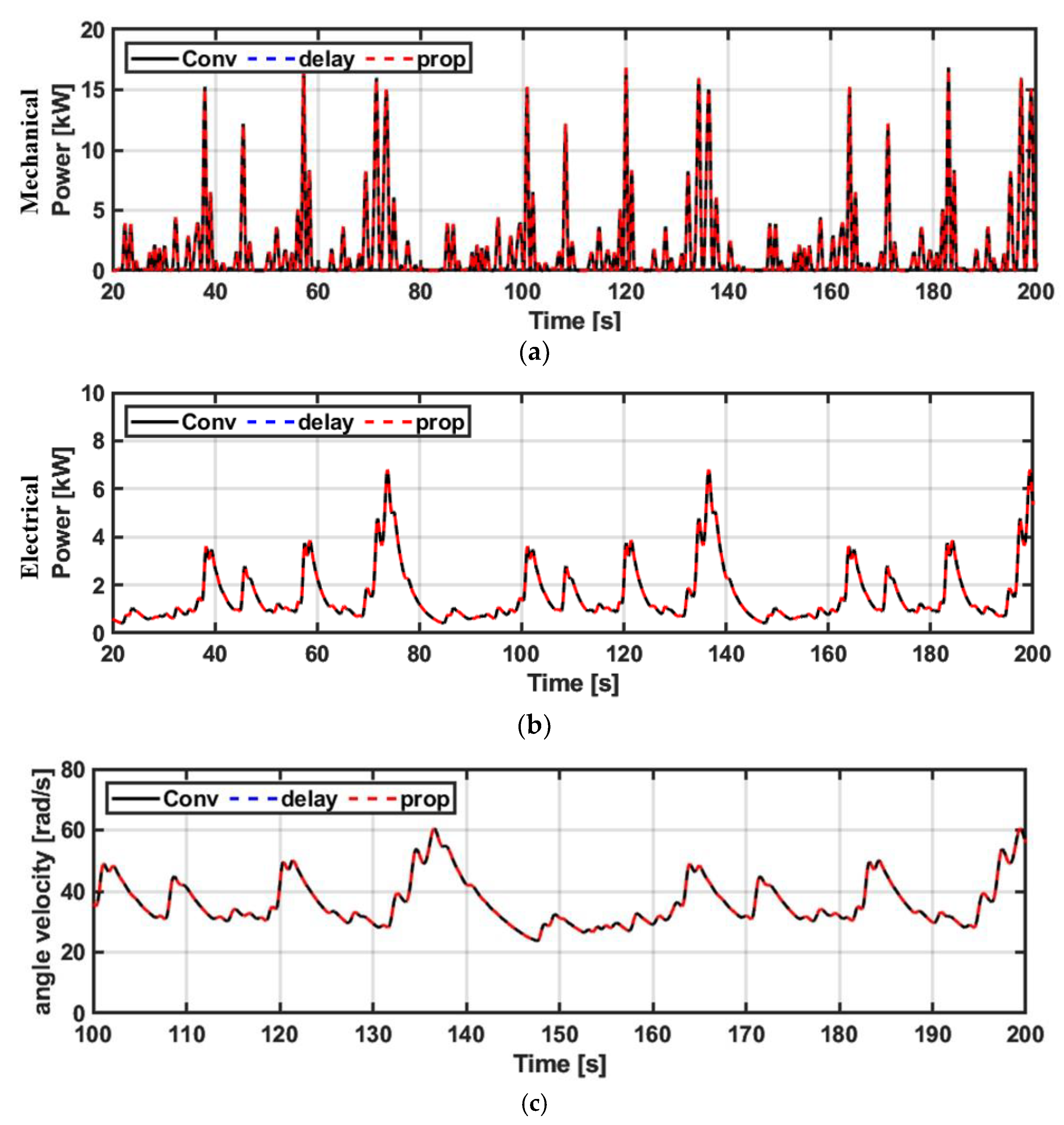
Figure 11 shows the mechanical and electrical powers of the OWC-WEC according to each rated controller. There are a total of three controllers compared in this paper: an ideal rated controller (Conv, black), a rated controller with a physical time delay similar to that in the actual system (delay, blue), and a proposed rated controller based on a deep learning model (prop, red). Because the existing rating controller performs rated power control without a time delay, both the mechanical and electrical power are stable, and the electrical power does not exceed the rated power. The rated power controller reflecting the physical time delay exhibits higher mechanical power and electrical power than the ideal rated controller because a time delay occurs. In particular, as the electrical power exceeds the rated power, this results in a reduction in the system stability and operating efficiency owing to mechanical and electrical fatigue. In conclusion, the wave condition under which the OWC-WEC can generate power is reduced. However, because the proposed method predicts the valve control angle for rated power control in advance by the time delay, it shows almost the same performance as the existing method, even though a physical time delay occurs. In other words, it can be confirmed that the mechanical and electrical powers were stable, and the electrical power did not exceed the rated power.
Figure 12 shows a histogram of the electrical power for each rated controller. Only the rated controller reflecting the time delay exhibited power exceeding the rated power.
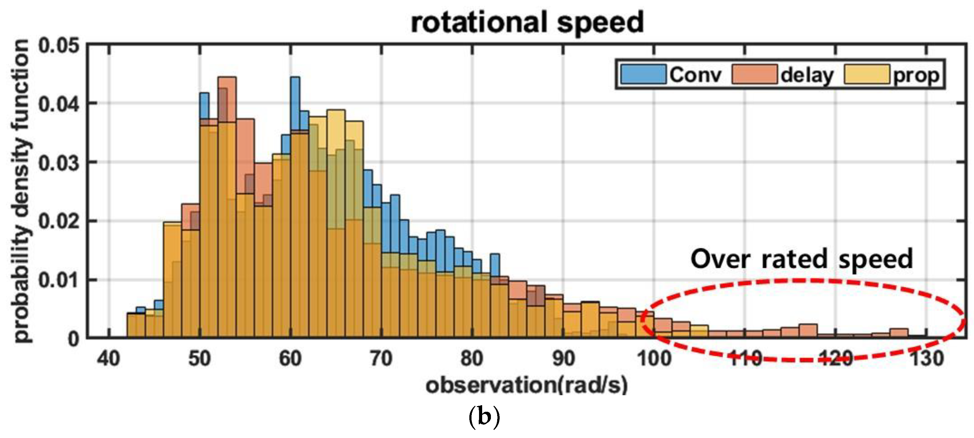
Figure 13 illustrates the angular velocity of the turbine and the corresponding histogram for different rated power controllers in OWC-WECs. The conventional rated power controller (Conv) without time delay ensured that the turbine angular velocity did not exceed the rated value. In contrast, the rated controller incorporating the physical time delay, similar to the actual system, continuously monitors the portion where the angular velocity exceeds the rated value due to the time delay. As depicted in
Figure 13b, the rated controller accounting for the physical time delay occasionally generated values surpassing the rated angular velocity. However, the proposed rated power controller, which predicts the valve control angle in advance and accounts for the system’s time delay, only slightly exceeded the rated angular velocity. It is important to note that the deep learning algorithm may introduce some errors, making the proposed controller less than ideal compared to the existing rated controller.
Figure 14 illustrates the valve control angle of the OWC-WECs for each rated power controller. It is evident that the valve control angle of the rated power controller with the physical time delay lags behind that of the ideal rated controller with time delay. Consequently, this delay leads to exceeding the rated power value. However, it is observed that the proposed method’s valve control angle closely resembles that of the ideal rated controller despite the presence of time delay.
Figure 15 presents the voltage and current profiles of the generator for each rated controller. As mentioned earlier, the rated power controller incorporating the physical time delay results in voltage and current values exceeding the rated limits. In contrast, the proposed method demonstrates performance comparable to the ideal rated controller. This indicates that the proposed method can establish a stable rated controller by leveraging a deep learning algorithm–based approach to predict the valve control angle, effectively compensating for the unavoidable physical time delay.
4.2. Input Data for Rated Control Performance Verification (Hs = 0.75 m, Tp = 4.75 s)
Figure 16 displays the input data for irregular waves when the rated controller is not active. The figure includes the spectrum of the irregular wave energy, the input time series, and the duct flow velocity. The performance of each rated controller was verified under identical input conditions. In this scenario, the wave condition Hs = 0.75 m, Tp = 4.75 s was selected, representing a situation in which the rated controller is not in operation. This choice confirms that consistent performance is expected regardless of the specific controller when it is not active.
Figure 17 illustrates the valve control angles for each controller under the input conditions presented in
Figure 16. In
Figure 16, the depicted input condition corresponds to a situation in which the rated controller is not operating. Consequently, for all controllers, the valve control angles exhibit a value of “0”. In other words, when the energy levels are below the rated energy threshold, the outcome remains the same regardless of the controller utilized. The graph provides confirmation that no operation signal is generated based on the error of the deep learning algorithm.
Figure 18 shows the mechanical power, electrical power, and angular velocity of the turbine of the OWC-WEC according to each rated controller. It can be confirmed that all the output results appear the same because at operating conditions below the rating the rated controller does not operate.
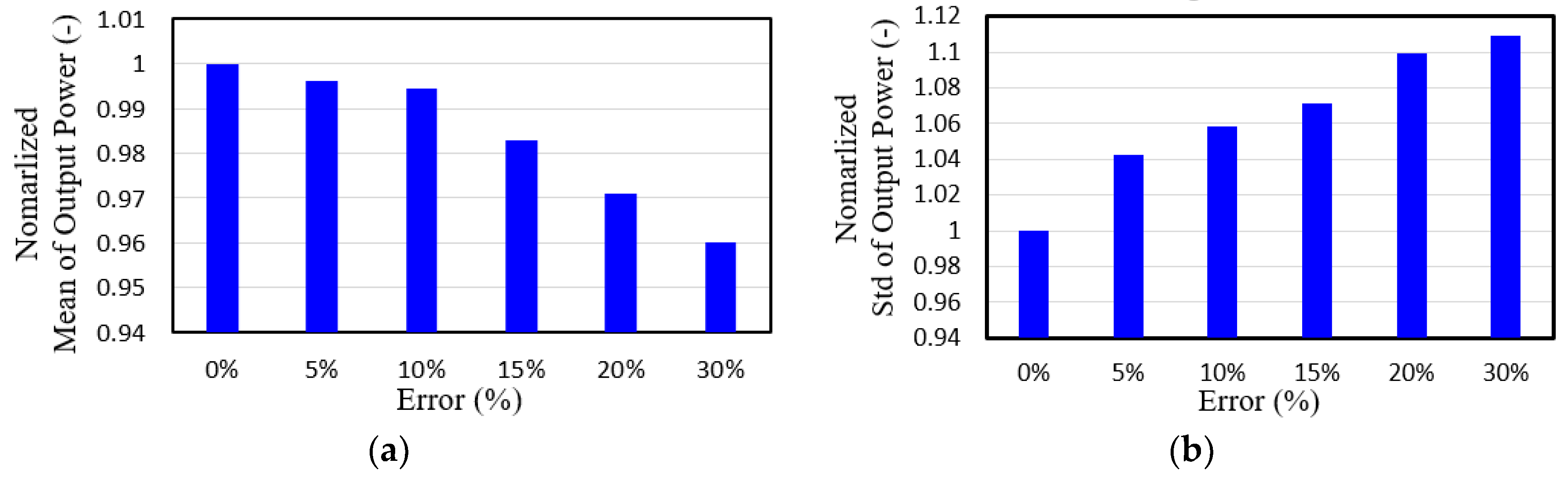
Figure 19 shows the average power generation and the standard deviation of the power generation according to the change in the error rate of the deep learning algorithm of the proposed rating controller. An error of 0% represents the amount generated by the ideal rated controller. The average generated amount and the standard deviation of the generation amount were standardized based on the ideal rated controller. As the error rate increased, the average power generation decreased. When the error rate was 30%, the average power generation decreased by approximately 4%. In addition, as the error rate increased, the standard deviation of the power generation increased by approximately 11%, based on an error rate of 30%. This is because a large amount of power exceeding the rated power was generated owing to an increase in the error rate. The average error rate of the controller in this paper was set as a target within 5%.
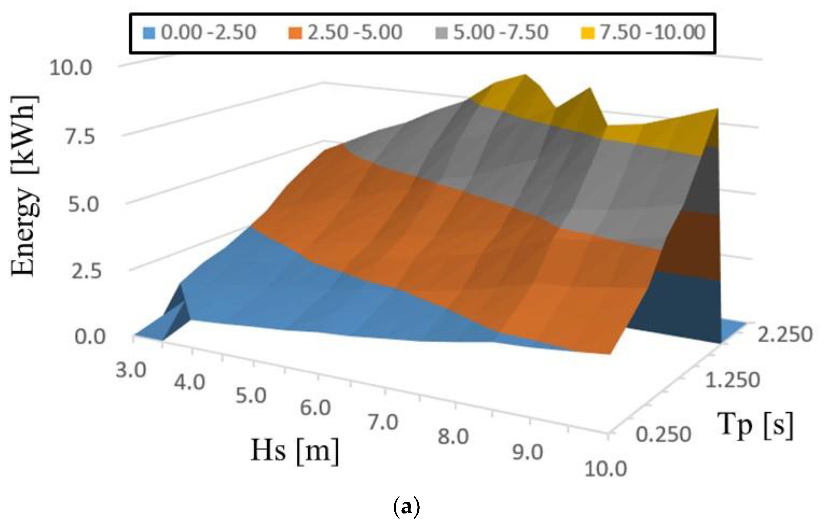
Figure 20 shows the output energy of each controller according to the input energy change. For the wave conditions (Hs, Tp) shown in
Figure 20, a comparative analysis of the output energy was performed based on conditions that may occur in the sea area where the target wave power generator is installed (
Figure 8). The part represented as zero in the average power generation data is a wave condition in which continuous power generation is difficult because it exceeds the rated power. Because the ideal rated controller (
Figure 20a) and the proposed controller (
Figure 20c) are not affected by the time delay, generation is possible over a wider range of wave conditions. However, the rating controller (
Figure 20b) that reflects the time delay of the actual system confirms that wave conditions that can generate power exceeding the continuous rated power result in a decrease in overall power generation. In conclusion, the proposed rating controller can generate power over a wider range of wave conditions because it can control a rating similar to the existing ideal rating controller, even though a physical time delay occurs on the actual system. Thus, the proposed rating controller can increase the annual power generation of OWC-WECs.
Table 1 shows the annual power generation for each controller. It can be seen that the controller with time delay reduces power generation by about 31% compared to the ideal conventional controller, but the proposed algorithm only reduces it by about 0.4%.
5. Conclusions
OWC-WECs have been widely studied worldwide owing to their high energy potential; however, problems remain to be overcome owing to their irregular input energy characteristics. In this study, research on a stable rated power controller was conducted to enable continuous power generation, even with irregular wave energy. In real systems, it is difficult to configure a precisely rated controller because physical time delays inevitably occur. Thus, exceeding the rated power reduces the stability and utilization rate of the system. Therefore, this study proposes a rated power controller that compensates for the unavoidable time delay of the system by applying a deep learning algorithm. The algorithm applied in this study was learned based on the operation data of the target wave power generator, and learning was performed based on the time delay of the actuator of the target wave power generator. As a results, even if a physical time delay occurs, it enables an accurate rating control, similar to an ideal rating controller, by predicting the time. In addition, by performing an analysis based on the error rate of the deep learning algorithm, the performance of the proposed rating controller to which the deep learning algorithm was applied was closely analyzed. In conclusion, the proposed rated controller enables power generation under various wave conditions by compensating for the unavoidable time delay of the frequency-column wave power generator, which increases the annual power generation. These algorithms are expected to significantly increase the annual power generation of wave power devices. As a future study, we plan to perform analysis by applying the algorithm to a real sea area model and design a specific deep learning model based on data gathered over a long time.


