Abstract
Thermoelectric technology is an effective strategy to convert low–grade waste heat to electrical energy directly. Thermoelectric generators (TEGs) have been extensively studied in various waste heat scenarios, such as vehicle exhaust, metal casting processes and more. However, industrial pipelines also possess high levels of heat and wide distribution, yet there is limited research on TEGs for use in these pipes. The challenge in designing a TEG lies in the heat collector, which is complicated by the distinct structural differences between pipe and plate–shaped TEMs. Ultimately, we propose an arch bridge–shaped heat collector for the pipe to recover wasted thermal energy. The effects of some key factors, such as topology of TEMs, heat source temperature, cooling water temperature and velocity, on the generating performance are studied. The TEG achieved a temperature difference of 65.98 °C across the two ends of the TEM, resulting in an output power of 17.89 W at an open–circuit voltage of 133.35 V. This provides evidence that the designed heat collector is a feasible solution for recovering waste heat from pipes using TEG technology. This work provides reliable experimental data and efficient design for the application of TEGs in industrial pipes.
1. Introduction
In recent years, energy conservation and industrial emission reduction have become an important global issue owing to the increasing prominent problems of energy shortage and environmental pollution [1,2,3]. Waste heat recovery is an important strategy for reducing energy consumption. Industrial waste heat, characterized by its large quantity and wide distribution, has attracted more attention in the area of energy utilization [4,5,6]. Thermoelectric technology can directly convert low grade waste heat to universal electrical energy based on the Seebeck effect. The thermoelectric module (TEM) has the advantages of simple construction, no moving parts, no noise, no pollution and long service life [7,8,9,10]. For these benefits, the thermoelectric generator (TEG) is considered to be a promising potential power generation technology in waste heat recovery [11,12,13,14].
Many TEGs have been designed for waste heat recovery in various industrial scenarios, such as metal casting processes [15], glass melt processes [16], high–temperature catalytic reactors [17], sugar mill boilers [18] and industrial flue gas [19]. Marit et al. [15] employed a combination of field experiments and a steady–state mathematical model to explore the potential for generating power from temperature differentials in waste heat produced during silicon casting. A 0.25 m2 TEG was produced using 36 bismuth telluride thermoelectric components in the casting area of their silicon plant, achieving a maximum temperature difference of 100 °C and a peak power output of 160 W/m2. Computational simulation was utilized to optimize the TEG’s performance. Yazawa et al. [16] designed a plate–type TEG structure that enables the recovery of thermal energy from glass melting processes, without interfering with normal operations, and optimizes waste heat recovery at each stage of the process. After optimization, the temperature difference power generation system can generate 55.6 kW of electricity with an efficiency of over 15% in a glass production facility with a daily output of 500 tons, according to theoretical calculations. Ma et al. [17] developed a TEG to recover waste heat from a biomass gasifier with an outlet temperature ranging from 340 to 500 °C. The TEG was integrated onto the surface of a catalytic reactor and consisted of a collector plate, cooling tubes and eight bismuth telluride thermoelectric modules. Results indicated that the maximum output power and power density achieved by the TEG were 6.1 W and 193.1 W/m2, respectively. Punin et al. [18] fabricated a TEG to recover waste heat from the sugar industry at 200 °C. The TEG utilized 10 thermoelectric devices, which were split into two parallel systems, each consisting of five thermoelectric modules connected in series. By using an electric heater, to simulate the tube wall temperature heat source of a sugar boiler, and cooling water as the cold end, this TEG can convert 11.5% of thermal energy into electrical energy at a matched load of approximately 1.65 Ω. As a result, the power generated by the TEG is roughly 126.15 W. Meng et al. [19] designed a TEG with a cylindrical structure for industrial waste gas heat recovery. The effects of key variables, such as exhaust gas inlet temperature, heat transfer coefficient of exhaust gas and cooling water, on the thermoelectric performance of the TEG were analyzed. Enhancing the heat transfer from the gas heat source can effectively improve the output performance of a TEG. At a hot end temperature of 350 °C, electricity generation can reach up to 1.47 kW per square meter with a thermoelectric conversion efficiency of 4.5%. The industrial waste heat is usually from high–temperature gas [20,21,22] or the surfaces of high–temperature equipment [23]. The plate–type [15,16,17,18] and tubular–type [19] are the most used TEG constructions for the foresaid heat sources. TEG is mainly composed of three parts: TEMs, hot ends and cold ends [24,25,26]. Bismuth telluride, lead telluride and skutterudite are the three main thermoelectric materials that have been practically applied in TEMs [27,28,29]. The working temperature ranges of the three materials are 20–300 °C, 300–600 °C and 600–1000 °C [30,31], respectively. The Pi–type TEM with the plate structure is the most used device [32,33]. At the hot end, a thermal collector needs to be designed to connect the heat source with the TEM. One side of the thermal collector is usually built using a planar construction to contact the TEM. The other side needs to be designed with various structures to contact with heat source. Fin and heat pipe are the two major patterns to collect heat from flue gas through convection heat transfer [34,35,36]. Plate–type hot end is a simple and effective heat collection construction for a flat and large size heat source, such as the surface of boilers [37]. The majority of cold ends usually use the cooling water board because cooling water systems are often available in industrial factories [38,39,40].
Industrial pipeline walls, such as in the material transfer pipes of the petrochemical industry, also produce vast waste heat. The temperature of the pipe wall is usually about 120–160 °C. In this waste heat condition, the challenge is how to design a TEG to recover the waste heat, while leaving the normal operation of the industrial pipes largely unaffected.
In this work, a TEG is produced to recover the waste heat from industrial pipes. The research includes three main aspects: (1) TEG structure design; (2) analysis of the influence law of various operating conditions on TEG performance; (3) evaluation of TEG system loss and its causes based on single TEM performance and operating temperature difference; (4) the correctness of the design, which can be assessed by the system loss of the TEG. Once we obtain results on TEG performance at various conditions, we can adjust the TEG to meet specific load parameters. When the temperatures of heat source and cooling water are 165 °C and 20 °C, a temperature difference of 65.98 °C on the TEMs is reached. The open–circuit voltage and maximum output power are 133.35 V and 17.89 W. The conversion efficiency could reach 2.67%. Since the waste heat of the industrial pipelines is colossal, our device could generate tremendous electrical energy.
2. Design and Development of the TEG
Figure 1 shows an image of material transfer pipelines and a cooling water system in the petrochemical industry, photographed on a field trip. The temperature of the outer wall is in the range 120–160 °C, which represents low temperature waste heat. The heat accumulated on the surface of the pipe wall is directly diffused to the outside environment without being used, which not only causes energy waste but also brings environmental problems. In this paper, we design and develop a TEG for recovering waste heat from the pipe wall based on the following principles: (1) installing the TEG on the pipe wall without affecting its proper functioning; (2) ensuring that the installation and operation of the TEG do not interfere with the material traveling through the pipe; (3) designing a suitable and efficient heat collector structure that takes into account both the shape of the pipe and the TEM; and (4) developing a fixation and pressure structure to secure both TEM to TEG, as well as TEG to pipe.
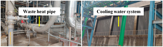
Figure 1.
Image of a high–temperature industrial pipe and cooling water system in a chemical plant.
In addition, the II–type TEM with flat structure is currently the most technologically mature and high–performing thermoelectric device, and it is the only commercial device. We have utilized bismuth telluride TEMs with a flat structure in this paper, as these materials exhibit the best thermoelectric performance between room temperature and 300 °C.
2.1. Generating Performance of TEM
The size of the TEM was 25 mm (length) × 25 mm (width) × 3.5 mm (height), and has 126 pairs of bismuth telluride thermoelectric legs. The generating performance of the TEM is the key factor for the TEG, and is measured to evaluate the generator output of the fabricated TEG. A sketch–map of the test condition is shown in Figure 2a. A heating platform was used as the hot end, and the test temperature was set to 40–180 °C, owing to the temperature of industrial piping. A water–cooling plate, connected to a chiller, was used as the cool end, and the test temperature was set to 20 °C based on the temperature of the cooling water system in the factory. Gold silicone grease was coated on both sides of the TEM to decrease the contact thermal resistance between TEM and hot and cold ends. Open–circuit voltage (VOC) and maximum output power (Pmax) of the TEM are core factors of generating properties. VOC can be tested by a voltmeter. Pmax refers to the output power, and it reaches a maximum when the load resistance is equal to the power source resistance [22]. In the test process, we adjusted the load resistance to obtain Pmax using an electronic load tester (IT8512B+, ITECH, Nanjing, China). The results are displayed in Figure 2b at different hot end temperatures. VOC and Pmax are both monotone, increasing with hot end temperature increment as the temperature difference of the TEM rises. When the hot end temperature increases from 40 °C to 180 °C, VOC ranges between 1.027 and 7.201 V, and Pmax ranges between 0.068 and 2.378 W. The results of VOC and Pmax for the TEM with different temperature differences can be used to assess the system loss of generating performance in a TEG.
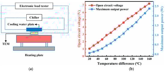
Figure 2.
(a) Sketch–map of the testing method. (b) Generating performance of a single TEM.
2.2. TEG Design and Experiment Platform Build
Figure 3a depicts a structural diagram of the TEG that was fabricated in accordance with the above design principles. It mainly consists of TEMs, a clamping fixed frame, a cold–water plate and an arch bridge–type heat collection structure. Because the surface of the pipe is curved and a TEM is a flat structure, TEMs cannot be directly attached to the pipe surface. Therefore, the design of TEGs is hindered by the complexity of the heat collector structures. As a solution, an arch bridge–shaped heat collector is proposed, based on the geometric characteristics of pipes and TEMs. One side of the arch bridge is plane, to connect with the plate TEMs, another side is arc–shaped, to fit the pipe. Considering the flexibility of installation and disassembly as well as the convenience of maintenance, the hot end is designed as a split type. The arch bridge hot ends can be closely assembled with the pipe via bolt fastenings. The investigation revealed that the material–conveying pipe is made of steel and has a diameter of Φ 250 mm. We have reduced the pipe size to Φ 80 mm, which is approximately one–third of the actual industrial pipe, for convenient experimentation purposes. We used a solid steel cylinder (Φ 80 mm × 500 mm) to simulate the industrial pipelines. The hot ends are built using aluminum material for its efficient heat transfer and light weight. The size of the plane side is 250 mm (L) × 84 mm (W). The cylinder is heated by three heating rods at its center. The interspace between the hot ends and the pipe is filled with thermally conductive silicone grease to reduce the contact thermal resistance. The cold ends are aluminum cooling water plates connected with a chiller, simulating the cooling water system in the industrial factory. The arrangement mode of the TEMs is three rows on each hot end, each row includes nine TEMs with series connection mode. In total, there are 54 TEMs in this TEG. The thermally conductive silicone grease is also coated on both sides of the TEMs to reduce contact thermal resistance. In addition, a fastening structure was designed to assemble the hot ends, TEMs and cold ends. It includes fastening screws, a fastening frame and pressure equalizing plates. The pressure equalizing plates can provide every TEM with uniform stress. The fastening structure can exert further pressure to improve the contact between TEMs and hot and cold ends. The fastening structure, made of steel material, plays the multiple roles of support, fixation and pressurization. Figure 3b shows an image of the TEG. The TEG structure is convenient for online installation and maintenance, and it can be extended according to the diameter and length of the industrial pipe.
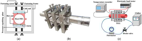
Figure 3.
TEG plant and system diagram. (a) Structure diagram of the TEG; (b) image of the TEG; (c) flow chart of the experimental platform.
To evaluate the generating performance of the TEG, an experimental platform was set up, as shown in Figure 3c. The experimental platform was equipped with multi–channel temperature acquisition tester, electronic load tester, flow meter, channel control valve, chiller and other experimental instruments for testing the generating performance of the TEG. The temperature recorder (EX3008, Toprie, Shenzhen, China) was used to record the temperature of the pipe wall, hot and cold ends, inlet and outlet water. The electronic load tester (IT8512B+, ITECH, Nanjing, China) was used to measure the voltage, electric current and output power. The flow meter (HXLD–DN8) was used to test the flow velocity of the cooling water. The drain valve (DUC–8) was used to control the cooling water flow.
3. Results and Discussion
Using the built TEG and experimental platform, the generating performance of TEG was studied under the influence of different factors using a controlled variables analysis method, such as thermoelectric module topology, cold end flow rate, hot end temperature and cold end temperature. The heat resistance distribution of the TEG was analyzed by the heat transfer model. In addition, the voltametric characteristics of the TEG were studied in detail. The accuracy of TEG output performance measurement is mainly affected by the high–power heating rod, water cooler and flowmeter. To minimize errors caused by temperature and water flow rate fluctuations, measurements should only be taken when the temperature is stable at 1 °C and the water flow rate remains within a range of 0.05 m/s.
3.1. Analysis of Hot End Uniformity
The uniformity of the hot end temperature is an important factor for TEG generating performance. Even temperature distribution ensures consistent electrical output of each TEM, thereby avoiding the electric energy loss caused by the dropout voltage [25]. Sixteen points for the temperature measurement are arranged on the two hot end surfaces to assess the temperature uniformity. Figure 4a shows the location of the eight points on the top hot end. The position of the other eight points was arranged on the bottom hot end. Figure 4b shows the results at different pipe wall temperatures (80 °C, 100 °C, 120 °C, 140 °C and 160 °C) without cooling water plates. The temperature of the hot end eventually converges, and the sixteen values present good uniformity with a variation of about ±2 °C. This indicates that the arch bridge–type design is reliable, and it has excellent heat transfer performance. The temperature of the heat rods was about 5 °C higher than that of the pipe wall, caused by heat emission to the environment. We took the temperature of the heat rods as the standard source, rather than that of pipe wall, in the follow–up experiments. Most heat is taken away by the cooling water, leading to the further reduction of the pipe wall temperature. Then, we assembled the TEG with good insulation measures.
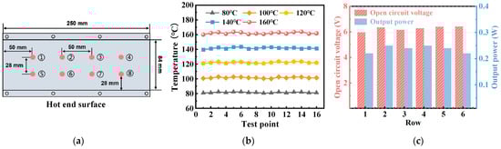
Figure 4.
(a) Distribution of temperature measurement points on the heat collector; (b) the temperature distribution of the collector at each temperature point; (c) the uniformity of power generation performance of six thermoelectric modules at 80 °C.
The open circuit voltage (Voc) and the maximum output power (Pmax) of the six rows of TEMs were measured to estimate the generating performance uniformity of each row. Voc was tested by the electrical load tester. Figure 4c shows Voc and Pmax when heat source (Th) and cooling water temperature (Tc) are 85 °C and 30 °C, respectively, with a water velocity (vw) of 1 m/s. The measured temperatures of the pipe wall and hot ends are 62.84 °C and 46.93 °C, respectively. The temperature difference is about 18.57 °C between the two ends of TEMs. Voc varies from 5.96 to 6.42 V, and Pmax varies from 0.22 to 0.25 W. It is evident that the generating performance of every row is similar, which further confirms the temperature uniformity of the hot ends.
3.2. Topological Structure of TEMs
The topological structure of TEMs is a key influencing factor for TEG generation properties. As mentioned above, 54 TEMs were arranged in 6 rows with 9 TEMs per row, each row could be a module. In addition, the generating performance of each module is approximate due to the uniformity of the hot ends. In order to confirm the series and parallel mode, we designed four topological structures for the six modules, as shown in Figure 5a. A is all six thermoelectric modules connected in series; B is every two thermoelectric modules, first connected in parallel for three groups, and then connected in series; C is every three thermoelectric modules, first connected in parallel for two groups, and then connected in series. D is all six thermoelectric modules connected in parallel. Figure 5b shows the electrical generation performance of the TEG with four different topologies, with the experimental conditions of 85 °C for the heat source, 30 °C for the cold end and 1 m/s for the flow rate. The Voc values of the four topological structures are 37.59 V, 18.63 V, 9.5 V and 4.7 V, respectively. The Pmax values of the four topological structures are 1.52 W, 1.42 W, 1.35 W and 1.29 W, respectively. The A topology (six modules connected in series) has the maximum output power. It is evident that the output power declines with an increasing number of the parallel circuits. The main reason for the power loss is the voltage drop caused by the circumfluence loss in the parallel circuit. Although the Voc of the six thermoelectric modules is similar in the TEG, the circumfluence phenomena still occur due to the low difference in voltage between modules. Therefore, in order to obtain better electrical generation performance, all six modules were connected in series systems in subsequent experiments.
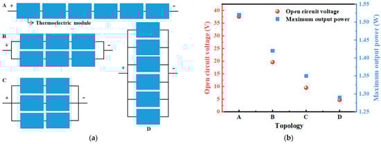
Figure 5.
The electricity generation performance of TEG with different TEM topological structures.
3.3. Influence of Cooling Water Velocity on Generating Performance
Different cooling water velocities have different heat–transfer processes and will differently affect the performance of the TEG. The cooling water flow rate is set at three levels, 0.5 m/s, 0.75 m/s and 1 m/s, according to the operating conditions of the chiller. Figure 6 shows the variations of Voc and Pmax with increasing vw (0.50 m/s, 0.75 m/s and 1.00 m/s) at different Th. In this measurement, Tc is fixed at 20 °C and Th was increased from 85 °C to 165 °C with an interval of 20 °C. Voc and Pmax both slightly increased with rising vw. When vw rises from 0.50 m/s to 1.00 m/s, Voc increases from 128.7 V to 133.35 V, and Pmax increases from 16.5 W to 17.89 W. Under this condition, the temperature difference of the TEM is 65.98 °C. The reason for the generating performance improvement is that the higher water velocity can take away more heat per unit time, thus causing a larger temperature difference. The conversion efficiency (η) can be calculated using Equation (1) [34]:
where Qout is the electrical energy generated by the TEG, Qin is the heat energy flow through the TEG, and Pw is the power of the water temperature increase. Under these working conditions, the heat absorbed by the TEG was 367.22 J at 80 °C, 361.24 J at 100 °C, 398.84 J at 120 °C, 524.64 J at 140 °C and 669.56 J at 160 °C. Pw can be obtained from Equations (2) and (3):
where C is the specific heat capacity of the water (4.2 × 10³ J/kg·°C), ΔTw is the temperature difference of the inlet and outlet water, t is the unit time with value for 1s. mw, ρw and Qw are the mass, density and flow of the water, respectively. η reaches a maximum of 2.67% when Th is 165 °C, Tc is 20 °C (ΔTw = 0.77 °C) and vw is 1 m/s (Qw = 0.743 m3/h).
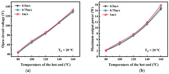
Figure 6.
Open–circuit voltage (a) and output power (b) of TEG at different heat source temperature and water velocity.
3.4. Influence of Hot and Cold End Temperature on Generating Performance
We fixed the water velocity to 1 m/s, in order to study the influence of Th and Tc on the generating performance of the prepared TEG. Figure 7 shows Voc and Pmax as functions of Th and Tc, in the form of a 3D color map. Voc and Pmax are determined by the temperature difference of TEMs. Therefore, they are obviously both increased by the rising Th and reducing Tc. Voc and Pmax are increased up to 127.88 V and 16.37 W, when Th is 165 °C, Tc is 20 °C. Under these conditions, the TEG absorbs 469.20 J of heat, the temperature difference of the TEM is 63.48 °C and η is 2.39%. The data fluctuate slightly relative to the data mentioned above (133.35 V, 17.89 W, under the same conditions). This variation may be caused by experimental error, such as the control precision of the heat and cold source.
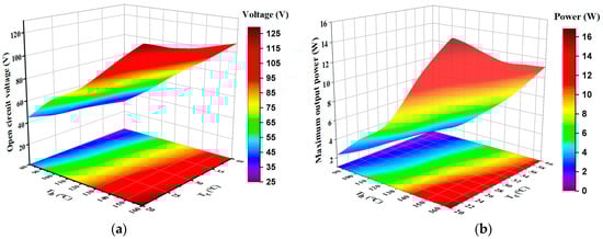
Figure 7.
The open–circuit voltage (a) and output power (b) of the TEG at different temperatures of hot and cold ends.
Based on the above electrical generating data, the average Pmax of a single TEM of the TEG can be calculated as 0.33 W (17.89 W, 54 TEMs) at a temperature difference of 63.48 °C. The TEMs average Pmax of the TEG is less than the Pmax (maximum output power of a single TEM at a temperature difference of 63.48 °C) tested at a single TEM in Section 2.1. The main reasons for this observation can be summarized in two aspects. First, multiple TEMs have more heat absorption capacity than a single TEM, and the temperature at the hot end of the TEG is decreased. Second, there will still exist electrical loss owing to the non–uniform electrical generation properties of each TEM in the TEG, although the connection mode is series. In addition, the conversion efficiency of the TEG achieves 2.67%, which is a TEG average at a temperature difference of about 60 °C.
3.5. The Thermal Resistance Distribution of TEG
A thermal resistance model for the prepared TEG was drawn to analyze the distribution of thermal resistance and temperature, as shown in Figure 8a. The temperature gradient drives the heat flux from the pipe wall to the cooling water plates. There are three contact layers between the pipe wall, thermal collectors, TEMs and cooling water plates. We used thermally conductive silicone grease as the contact layer to reduce the thermal contact resistance. The thermal resistances along the direction of heat flow are RS1, RH, RS2, RTEM, and RS3. RS1, RS2 and RS3 are the thermal resistances of the silicone grease and contact interfacial. The temperature of the pipe wall and thermal collectors, and the temperature difference, are shown in Figure 8b.
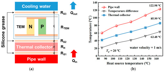
Figure 8.
(a) The thermal resistance model for the TEG; (b) The temperature of the different TEG parts.
When the temperature of the hot rods is 165 °C, the temperatures of the pipe wall and thermal collectors are 122.98 °C and 85.99 °C, and the temperature difference of the TEMs is about 63.48 °C. Most of the heat is taken away by the cooling water. When the heat balance is reached, the pipe wall can only maintain 122.98 °C with a loss of 42.02 °C. If we use the temperature to evaluate the thermal resistance, we may have T (RS1 + RH) = 36.99 °C and T (RS2 + RTEM + RS3) = 63.48 °C. Every RS1, RS2 and RS3 results in a temperature loss of 2–3 °C according to the measurement.
An ideal TEG, with the thermal resistances focused on the TEMs as much as possible, is desirable [41]. However, measurement results show that the thermal resistances of the heat collectors are high, since its volume is large. Therefore, to improve TEG output, reducing the wall thickness of the thermal collector is an effective approach.
3.6. Voltametric Characterization of TEG
The voltage–current and power–current curves are important bases for the power management of TEGs. By studying the effects of certain key factors, such as topology of the thermoelectric modules, temperature of the hot and cold source, and cooling water flow rate, on the thermoelectric performance of TEG, the operating conditions with the best generating performance of TEG can be confirmed. In this section, the voltametric characteristics of the TEG under optimal operating conditions (all the six modules connected in series, 20 °C at the cold end and 1 m/s cooling water flow rate) were studied. In order to obtain more detailed TEG voltametric characterization data, the hot temperature was used as a variable.
The relationship between current and voltage is nearly linear at different Th, since the internal resistance changes little at a constant temperature, as shown in Figure 9a. The voltage increases with increasing heat source temperature and reaches 123.14 V (open circuit voltage) at Th = 165 °C, Tc = 20 °C and vw = 1 m/s. Figure 9b shows the trends in output power for different load resistances with Th variation. The output power of the TEG first increases and then decreases with the rising current when the temperature of heat source is fixed. The parabolic rule of the output power expresses the definition of Pmax clearly. That is to say, the TEG reaches the maximum output power at about 16.36 W at Th = 165 °C, Tc = 20 °C and vw = 1 m/s, I = 0.26 A.
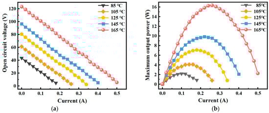
Figure 9.
The voltage–current (a) and power–current (b) curves of the TEG at Tc = 20 °C, vw = 1 m/s at varying Th.
4. Conclusions
We have developed a TEG specifically designed for recovering waste heat from industrial pipelines. Our innovative arch bridge heat collector, which is tailored to the shape of the pipes and incorporates TEM technology, can be installed and maintained, without disrupting normal pipeline operations, for the recovery of waste heat from industrial pipe walls. The study investigates the impact of thermoelectric module topology, heat source and cooling water temperatures, and water velocity on the generating performance of the TEG. The experimental results indicate that for achieving superior TEG output performance, the preferred topology of the thermoelectric module is a series structure with a high–temperature hot end, low–temperature cold end, and high flow rate conditions. When the heat source and cooling water are at temperatures of 165 °C and 20 °C, respectively, with a flow rate of 1 m/s, the TEG absorbs a total of 669.56 J of heat and achieves a temperature difference of 65.98 °C. The open–circuit voltage, maximum output power and conversion efficiency of the TEG are 133.35 V, 17.89 W, and 2.67%, respectively. The conversion efficiency of 2.67% is at an average level for TEG performance at this temperature difference. However, the thermal resistance of the heat collector could be decreased by reducing its weight according to the distribution of thermal resistance in order to improve TEG generation. The fabricated TEG can be viewed as a modular system, allowing for the development of a suitable TEG that meets specific application requirements based on experimental parameters. This work would be helpful in industrial pipe waste heat recovery.
Author Contributions
D.X., P.S. and J.J. designed this work. D.X., J.W. (Jianlin Wu) and Y.Z. designed and fabricated the TEG and carried out the generating performance. J.W. (Jiehua Wu) and X.T. performed the calculations. Y.Z., H.H. and J.H. did the data curation. D.X., P.S. and G.L. analyzed the experimental data and wrote and edited this manuscript. S.H. and J.J. provided the funding acquisition. All authors have read and agreed to the published version of the manuscript.
Funding
This research was funded by the National Natural Science Foundation of China (U21A2079, and 52002382), Zhejiang Provincial Key R&D Program (2021C01026), Zhejiang Provincial Natural Science Foundation of China (LR21E020002), Youth Innovation Promotion Association CAS (2019298), Zhejiang Provincial High–level Talent Special Support Plan (2020R52032) and Ningbo Key Research and Development Plan (2022Z187).
Data Availability Statement
All data used are reported here and/or in the cited literature sources.
Acknowledgments
Thanks to Ningbo Institute of Materials Technology and Engineering, Chinese Academy of Sciences for the financial support.
Conflicts of Interest
There are no conflicts of interest to declare.
Nomenclature
| TEG | Thermoelectric generator |
| TEM | Thermoelectric device |
| Voc | Open–circuit voltage |
| Pmax | Maximum output power |
| Th | Hot end temperature |
| Tc | Cold end temperature |
| vw | Water velocity |
| η | Conversion efficiency |
| Qout | Electrical energy generated by the TEG |
| Qin | Heat energy flow through the TEG |
| PW | Power of the water temperature increase |
| C | Specific heat capacity of the water |
| ΔTW | Temperature difference of the inlet and outlet water |
| t | Unit time with value for 1s |
| mW | Mass of the water |
| ρW | Density and flow of the water |
| QW | Flow of the water |
References
- Remeli, M.F.; Tan, L.; Date, A.; Singh, B.; Akbarzadeh, A. Simultaneous power generation and heat recovery using a heat pipe assisted thermoelectric generator system. Energy Convers. Manag. 2015, 91, 110–119. [Google Scholar] [CrossRef]
- Attar, A.; Lee, H.; Weera, S. Experimental Validation of the Optimum Design of an Automotive Air–to–Air Thermoelectric Air Conditioner (TEAC). J. Electron. Mater. 2015, 44, 2177–2185. [Google Scholar] [CrossRef]
- Sakdanuphab, R.; Sakulkalavek, A. Design, empirical modeling and analysis of a waste–heat recovery system coupled to a traditional cooking stove. Energy Convers. Manag. 2017, 139, 182–193. [Google Scholar] [CrossRef]
- Stijepovic, M.Z.; Linke, P. Optimal waste heat recovery and reuse in industrial zones. Energy 2011, 13, 341–363. [Google Scholar]
- Miró, L.; Brückner, S.; Cabeza, L.F. Mapping and discussing Industrial Waste Heat (IWH) potentials for different countries. Renew. Sustain. Energy Rev. 2015, 51, 847–855. [Google Scholar] [CrossRef]
- Huang, F.; Zheng, J.; Baleynaud, J.M.; Lu, J. Heat recovery potentials and technologies in industrial zones. J. Energy Inst. 2017, 90, 951–961. [Google Scholar] [CrossRef]
- Jang, J.-C.; Chi, R.-G.; Rhi, S.-H.; Lee, K.-B. Heat Pipe–Assisted Thermoelectric Power Generation Technology for Waste Heat Recovery. J. Electron. Mater. 2015, 44, 2039–2047. [Google Scholar] [CrossRef]
- Orr, B.; Akbarzadeh, A.; Mochizuki, M.; Singh, R. A review of car waste heat recovery systems utilising thermoelectric generators and heat pipes. Appl. Therm. Eng. 2016, 101, 490–505. [Google Scholar] [CrossRef]
- Kim, T.Y.; Negash, A.A.; Cho, G. Experimental study of energy utilization effectiveness of thermoelectric generator on diesel engine. Energy 2017, 128, 531–539. [Google Scholar] [CrossRef]
- Jaziri, N.; Boughamoura, A.; Müller, J.; Mezghani, B.; Tounsi, F.; Ismail, M. A comprehensive review of Thermoelectric Generators: Technologies and common applications. Energy Rep. 2020, 6, 264–287. [Google Scholar] [CrossRef]
- Suter, C.; Jovanovic, Z.R.; Steinfeld, A. A 1kWe thermoelectric stack for geothermal power generation–Modeling and geometrical optimization. Appl. Energy 2012, 99, 379–385. [Google Scholar] [CrossRef]
- Weng, C.-C.; Huang, M.-J. A study of using a thermoelectric generator to harvest energy from a table lamp. Energy 2014, 76, 788–798. [Google Scholar] [CrossRef]
- Özdemir, A.E.; Köysal, Y.; Özbaş, E.; Atalay, T. The experimental design of solar heating thermoelectric generator with wind cooling chimney. Energy Convers. Manag. 2015, 98, 127–133. [Google Scholar] [CrossRef]
- Al-Nimr, M.d.A.; Tashtoush, B.M.; Jaradat, A.A. Modeling and simulation of thermoelectric device working as a heat pump and an electric generator under Mediterranean climate. Energy 2015, 90, 1239–1250. [Google Scholar] [CrossRef]
- Børset, M.T.; Wilhelmsen, Ø.; Kjelstrup, S.; Burheim, O.S. Exploring the potential for waste heat recovery during metal casting with thermoelectric generators: On–site experiments and mathematical modeling. Energy 2017, 118, 865–875. [Google Scholar] [CrossRef]
- Yazawa, K.; Shakouri, A.; Hendricks, T.J. Thermoelectric heat recovery from glass melt processes. Energy 2017, 118, 1035–1043. [Google Scholar] [CrossRef]
- Ma, H.-K.; Lin, C.-P.; Wu, H.-P.; Peng, C.-H.; Hsu, C.-C. Waste heat recovery using a thermoelectric power generation system in a biomass gasifier. Appl. Therm. Eng. 2015, 88, 274–289. [Google Scholar] [CrossRef]
- Punin, W.; Maneewan, S.; Punlek, C. Heat transfer characteristics of a thermoelectric power generator system for low–grade waste heat recovery from the sugar industry. Heat Mass Transf. 2018, 55, 979–991. [Google Scholar] [CrossRef]
- Meng, F.; Chen, L.; Feng, Y.; Xiong, B. Thermoelectric generator for industrial gas phase waste heat recovery. Energy 2017, 135, 83–90. [Google Scholar] [CrossRef]
- Hsu, C.-T.; Huang, G.-Y.; Chu, H.-S.; Yu, B.; Yao, D.-J. Experiments and simulations on low–temperature waste heat harvesting system by thermoelectric power generators. Appl. Energy 2011, 88, 1291–1307. [Google Scholar] [CrossRef]
- Demir, M.E.; Dincer, I. Performance assessment of a thermoelectric generator applied to exhaust waste heat recovery. Appl. Therm. Eng. 2017, 120, 694–707. [Google Scholar] [CrossRef]
- Dong, X.-Q.; He, R.; Zhao, X.-C. Performance analysis of thermoelectric generation system with controlled heat distribution. Energy Convers. Manag. 2021, 245, 112–134. [Google Scholar] [CrossRef]
- Chen, L.; Lee, J. Efficiency enhancement of an industrial–scale thermoelectric generator system by periodically inputting thermal power. Energy Convers. Manag. 2016, 119, 75–89. [Google Scholar] [CrossRef]
- Lv, S.; He, W.; Jiang, Q.; Hu, Z.; Liu, X.; Chen, H.; Liu, M. Study of different heat exchange technologies influence on the performance of thermoelectric generators. Energy Convers. Manag. 2018, 156, 167–177. [Google Scholar] [CrossRef]
- Du, H.; Dong, C.; Liu, K.; Bu, Z.; Guo, W.; Ye, Y.; Liu, W. Investigation of thermoelectric performance based on thermal load with porous heat collector and traditional heat collector. Energy Convers. Manag. 2022, 251, 34–45. [Google Scholar] [CrossRef]
- Kim, D.H.; Seo, S.; Kim, S.; Shin, S.; Son, K.; Jeon, S.J.; Han, S. Design and performance analyses of thermoelectric coolers and power generators for automobiles. Sustain. Energy Technol. Assess. 2022, 51, 104–116. [Google Scholar] [CrossRef]
- Stoica, M.; Lo, C.S. Electrical transport properties of Co–based skutterudites filled with Ag and Au. Phys. Rev. B 2012, 86, 156–174. [Google Scholar] [CrossRef]
- Mamur, H.; Bhuiyan, M.R.A.; Korkmaz, F.; Nil, M. A review on bismuth telluride (Bi2Te3) nanostructure for thermoelectric applications. Renew. Sustain. Energy Rev. 2018, 82, 4159–4169. [Google Scholar] [CrossRef]
- Hao, X.; Chen, X.; Zhou, X.; Zhang, L.; Tao, J.; Wang, C.; Wu, T.; Dai, W. Performance Optimization for PbTe–Based Thermoelectric Materials. Front. Energy Res. 2021, 9, 54–71. [Google Scholar] [CrossRef]
- Chen, Y.; Hou, X.; Ma, C.; Dou, Y.; Wu, W. Review of Development Status of Bi2Te3–Based Semiconductor Thermoelectric Power Generation. Adv. Mater. Sci. Eng. 2018, 2018, 1–9. [Google Scholar] [CrossRef]
- Su, C.-H. Design, growth and characterization of PbTe–based thermoelectric materials. Prog. Cryst. Growth Charact. Mater. 2019, 65, 47–94. [Google Scholar] [CrossRef]
- Ebling, D.G.; Krumm, A.; Pfeiffelmann, B.; Gottschald, J.; Bruchmann, J.; Benim, A.C.; Adam, M.; Labs, R.; Herbertz, R.R. Development of a System for Thermoelectric Heat Recovery from Stationary Industrial Processes. J. Electron. Mater. 2016, 45, 3433–3449. [Google Scholar] [CrossRef]
- Bou Nader, W. Thermoelectric generator optimization for hybrid electric vehicles. Appl. Therm. Eng. 2020, 167, 56–61. [Google Scholar] [CrossRef]
- Kim, T.Y.; Kwak, J.; Kim, B.-W. Energy harvesting performance of hexagonal shaped thermoelectric generator for passenger vehicle applications: An experimental approach. Energy Convers. Manag. 2018, 160, 14–21. [Google Scholar] [CrossRef]
- Zoui, M.A.; Bentouba, S.; Velauthapillai, D.; Zioui, N.; Bourouis, M. Design and characterization of a novel finned tubular thermoelectric generator for waste heat recovery. Energy 2022, 253, 11–21. [Google Scholar] [CrossRef]
- Cao, Q.; Luan, W.; Wang, T. Performance enhancement of heat pipes assisted thermoelectric generator for automobile exhaust heat recovery. Appl. Therm. Eng. 2018, 130, 1472–1489. [Google Scholar] [CrossRef]
- Brazdil, M.; Pospisil, J. Thermoelectric Power Generation Utilizing the Waste Heat from a Biomass Boiler. J. Electron. Mater. 2013, 42, 2198–2202. [Google Scholar] [CrossRef]
- Ando Junior, O.H.; Maran, A.L.O.; Henao, N.C. A review of the development and applications of thermoelectric microgenerators for energy harvesting. Renew. Sustain. Energy Rev. 2018, 91, 376–393. [Google Scholar] [CrossRef]
- Casi, Á.; Araiz, M.; Catalán, L.; Astrain, D. Thermoelectric heat recovery in a real industry: From laboratory optimization to reality. Appl. Therm. Eng. 2021, 184, 98–116. [Google Scholar] [CrossRef]
- Fernández-Yáñez, P.; Romero, V.; Armas, O.; Cerretti, G. Thermal management of thermoelectric generators for waste energy recovery. Appl. Therm. Eng. 2021, 196, 137–145. [Google Scholar] [CrossRef]
- Luo, D.; Yan, Y.; Chen, W.-H.; Yang, X.; Chen, H.; Cao, B.; Zhao, Y. A comprehensive hybrid transient CFD–thermal resistance model for automobile thermoelectric generators. Heat Mass Transf. 2023, 211, 124203. [Google Scholar] [CrossRef]


Disclaimer/Publisher’s Note: The statements, opinions and data contained in all publications are solely those of the individual author(s) and contributor(s) and not of MDPI and/or the editor(s). MDPI and/or the editor(s) disclaim responsibility for any injury to people or property resulting from any ideas, methods, instructions or products referred to in the content. |
© 2023 by the authors. Licensee MDPI, Basel, Switzerland. This article is an open access article distributed under the terms and conditions of the Creative Commons Attribution (CC BY) license (https://creativecommons.org/licenses/by/4.0/).