Abstract
Grinding chatter is a kind of self-excited vibration in which the grinding system continuously absorbs energy from the grinding machine, increasing the mechanical energy of the system. Grinding chatter can damage the surface of the workpiece and accelerate the abrasion of the grinding wheel. The theoretical analysis of the grinding chatter for the beam surface was launched based on the behavior of a single abrasive grain, whose cutting thickness is a key factor affecting grinding stability. The dynamic grinding force model has been developed, which is the interaction interface between the grinding wheel and the workpiece. In this paper, rail beam grinding was taken as an example. The vibration performance of the rail beam was described with the Timoshenko beam. The characteristics of the frequency domain of the grinding wheel-workpiece system were observed, and the condition of the stability at any position in the longitudinal direction of the beam was gained, which could be quantitatively characterized with the stability limit curve. The grinding experiments of the rail beam surface demonstrated that as chatter developed, the chatter marks could be investigated on the surface of the rail, and the energy of the chatter signal was mainly concentrated around the chatter frequency, which was higher than the natural frequency of the grinding wheel.
1. Introduction
The stability of parameter-excited vibrations in fluid and mechanical systems, such as the wings in flight, pipes conveying fluid [1] and material machining, is critical to system performance. Under certain parameters, the stability of the system is destroyed, and chatter occurs. The phenomenon of chatter generated from the machining process is a self-exited vibration between the cutting tool and workpiece [2,3,4], which results in poor surface quality and dimensional accuracy of the workpiece and accelerates the abrasion of the tool [5,6,7,8,9]. Generally, as the final procedure of machining, grinding has significance for the quality of the workpiece [10,11,12]. Therefore, it is crucial to comprehend the mechanism of chatter to predict and avoid chatter in grinding operations [13]. Chatter is closely related to the dynamic characteristics of the tool and workpiece as well as the grinding parameters [14,15].
Since the second half of the 20th century, significant developments in grinding chatter research have been made. Hahn proposed an initial grinding chatter model utilizing the Nyquist criteria, which only considered the surface regeneration of the workpiece [16]. According to his model, stable and unstable grinding parameter regions could be gained. Snoeys et al. investigated stability in the cylindrical grinding process involving the regeneration of the workpiece and grinding wheel [17]. Thompson [18,19,20,21] studied double regeneration by deeply considering wheel and workpiece speed, contact stiffness and wave filtering. In the theory of Snoeys and Thompson, wheel regeneration only focused on the distributed radial wear along the circumferential direction of the grinding wheel, which was challenged by Li and Shin [22], who addressed the distributed grit dullness as a main factor relevant to chatter. This method was validated by comparing the simulated chatter frequencies and thresholds with the experimental results. In 2006, Li and Shin [23] proposed a time-domain dynamic model that expressed the cylindrical plunge grinding processes, which could predict grinding the chatter boundaries and growth rates. Later, an improved model focusing on transient chatter during spark-in and spark-out was developed by Li and Shin [24], which was experimentally identified. Chung et al. [25] developed a nonlinear chatter model of the cylindrical transverse grinding process, which included two-time delays originating from the regenerative effects of the workpiece and the grinding wheel. Yan et al. [26] employed DDEs and PDEs to investigate grinding self-interrupted chatter in cylindrical plunge grinding, in which a loss of contact between the workpiece and the grinding wheel occurred. Yan et al. [27] considered the lateral and torsional workpiece movements in the cylindrical plunge grinding process and proposed a dynamic model that involved state-dependent time delays for regenerative effects.
The studies mentioned above focus on rigid workpieces. By contrast, flexible workpieces, including slender shafts, rail beams, thin-walled parts and so on, have a greater possibility of chatter. For instance, in rail beam grinding, the rail beam was clamped at the ends. The stiffness of the rail beam in different longitudinal positions was different, which contributed to the complexity of the vibration and increased the possibility of chatter. On the other hand, the grinding wheel was regarded as an entirety without considering the interaction between the single abrasive particle and the workpiece in the present studies. In this paper, the chatter mechanism during rail beam surface grinding was analyzed from the perspective of a single grain, taking into account the longitudinal position of the beam. A chatter forecast model is proposed, which could provide evidence to avoid chatter in the grinding process.
2. Modeling of the Dynamic Grinding Force
In the grinding process, the stability of the system was affected by the dynamic interaction between the grinding wheel and the workpiece, namely, the dynamic grinding force. Thus, the dynamic grinding force equation was deduced based on the dynamic cutting thickness of a single abrasive grain. For simplicity, it could be assumed that the abrasive grains on the grinding wheel were evenly distributed in the axial and circumferential directions.
2.1. Dynamic Cutting Thickness of a Single Abrasive Grain
In the grinding process, if the relative vibration of the grinding wheel and the workpiece was not considered, the motion path of a single abrasive grain relative to the workpiece was cycloid, as shown in Figure 1. As two adjacent abrasive grains are at the same angle , the instantaneous cutting thickness was , which was determined by grinding parameters (abrasive wheel peripheral velocity, grinding depth, workpiece velocity), the distribution interval of abrasive grains along the wheel circumference and angle . In the actual grinding process, the relative vibration between the grinding wheel and the workpiece resulted in the actual trajectory of the abrasive particle fluctuating near the cycloid. Then, the instantaneous cutting thickness was expressed as , whose expression was:
where is the dynamic cutting thickness caused by the relative vibration of the grinding wheel and workpiece, which could be calculated by Equation (2).
where , , and are the displacements of the grinding wheel and workpiece in the Y and X directions during the grain passing period
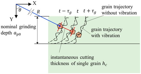
Figure 1.
Trajectory of a single grain.
2.2. Grinding Force Caused by Dynamic Cutting Thickness
The dynamic grinding forces in the tangential and normal directions of a single grain were:
where and represent the tangential and normal grinding forces of a single grain, respectively, and and are the tangential and normal cutting coefficients, respectively, which were constant.
Hence, the component force of a single grain in the X and Y directions could be expressed as:
In the grinding arc, several abrasive grains participated in the cutting process (as shown in Figure 2); then, the grinding forces per unit width of the grinding wheel, both tangential (X direction) and normal (Y direction), could be expressed as:
where is the cut-out angle of the abrasive grain, which was very small; thus, the length of the grinding arc could be approximated as:
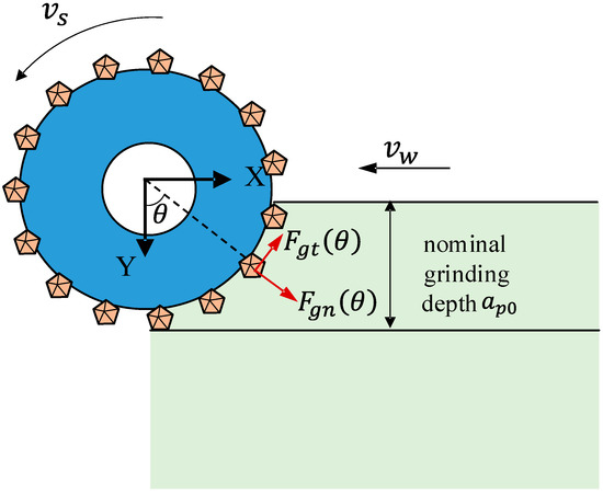
Figure 2.
Multiple abrasive particles cut together in the grinding arc.
Hence,
Considering that the abrasive grain density on the grinding wheel surface was large, the spacing between adjacent abrasive particles was small, and the angle of the abrasive particles in the grinding arc region changed approximately and continuously; therefore, Equation (9) could be approximated as:
where is the number of grains in the circumferential direction of the grinding wheel.
Substituting Equations (2), (7) and (8) yielded:
The degrees of freedom at both ends of the beam in the x direction were restricted; therefore, the grinding force in the x direction was ignored in this research.
Set
Figure 3 illustrates the variation in each element in the matrix with grinding depth: as the grinding depth increased, the value of increased rapidly first and then slowly, before finally, the change was approximately linear. The values of , and were approximately linear with an increasing grinding depth. At the same grinding depth, the value of was much larger than that of , and ; therefore, in order to simplify the calculation of the grinding force in the Y direction, the values , and were ignored.
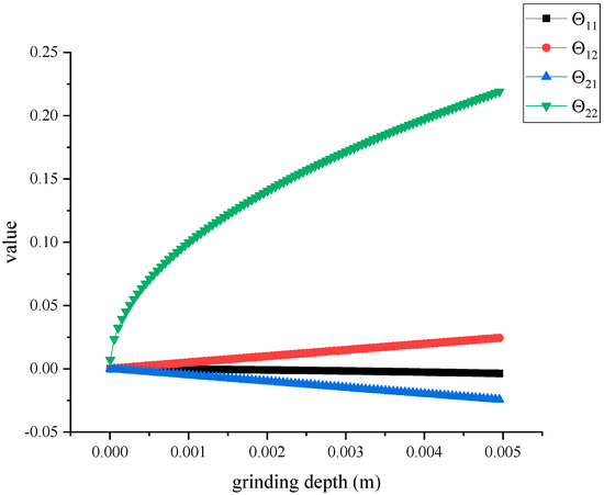
Figure 3.
The variation in each element in the matrix with grinding depth.
Set
where represents the coefficient of the grinding force in the Y direction. According to Equation (11), is the function of the depth of cut , i.e., .
Substituting Equations (3) and (4) yielded:
3. Dynamic Equivalent Model of Grinding Wheel and Workpiece System
In this research, rail grinding was taken as an example to analyze the stability of beam grinding.
3.1. Dynamic Characteristic Test of Grinding Wheel and Workpiece
To acquire the dynamic characteristics of the grinding wheel and workpiece (rail), frequency response function tests were carried out. As demonstrated in Figure 4a, a rail beam was supported by the fasteners at both ends of the workbench of the grinder. The distance between the center of the two fasteners was 600 mm, which was the actual track distance. The upper surface of the rail in the center of the span was selected as the excitation point, and a tri-axis accelerometer was arranged at the side position of the rail in the center of the span. The positions of the impulse point and sampling point of the grinding wheel are shown in Figure 4b. The results of the test are summarized in Table 1.
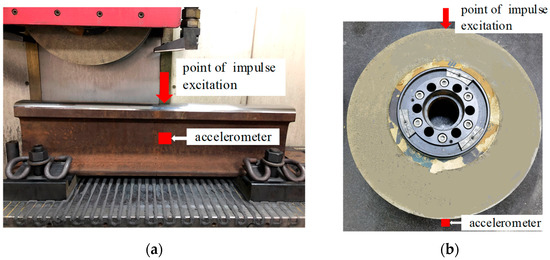
Figure 4.
Position of excitation point and collection point in frequency response function test of wheel and workpiece.

Table 1.
Results of dynamic characteristics of grinding wheel and workpiece.
3.2. Dynamic Model of the Grinding Wheel
According to the test results of the dynamic characteristics of the grinding wheel (including the spindle), combined with the existing research [9,28], the grinding wheel-spindle system was equivalent to the damped single degree of a freedom vibration model (illustrated in Figure 5), whose governing Equation is:
where , and are the equivalent mass, damping and stiffness of the grinding wheel (including the spindle) and , and are the acceleration, velocity and displacement in the Y direction, respectively. The natural frequency and damping of the grinding wheel-spindle system (damped single-degree-of-freedom vibration system) were calculated from the dominant natural frequency and damping ratio acquired from the test.
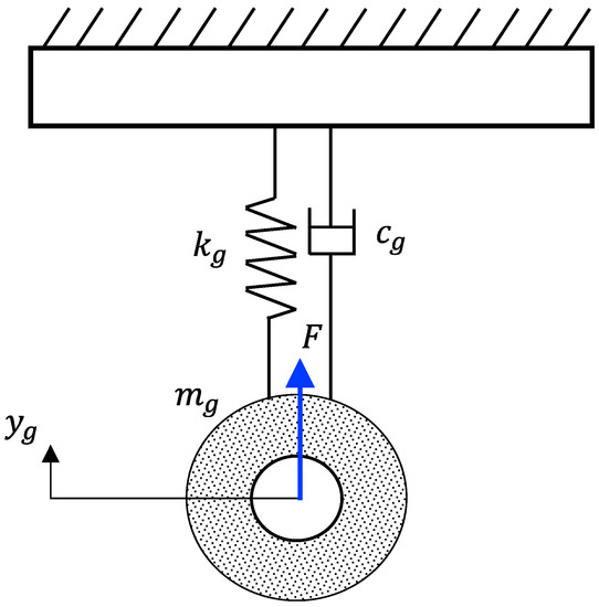
Figure 5.
Equivalent dynamics model of grinding wheel (including spindle).
3.3. Dynamic Model of the Workpiece
The span and height of the rail beam were 600 mm and 150 mm, respectively, and the span height ratio was four, which belonged to the short beam. It was necessary to consider the influence of shear deformation and moment of inertia on the vibration of the beam. Thus, the Timoshenko beam model [29,30] was used to describe the vibration behavior of the rail beam (illustrated in Figure 6). The vibration equation of the Timoshenko beam under the grinding force in the Y direction was:
where , and are the density, Young modulus and shearing modulus of the elasticity of the material of the rail, respectively; , , and are the cross-sectional area, the moment of inertia, the radius of gyration and coefficient of the shear stress inhomogeneity of the rail beam, respectively; represents the displacement of the rail beam at a longitudinal position at time ; and is the Dirac function. The values of each parameter are shown in Table 2.
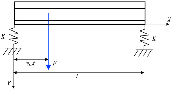
Figure 6.
Equivalent dynamics model of the workpiece (rail beam).
Table 2.
Properties of the workpiece (rail beam).
In practice, the rail was supported by fastenings and sleepers on the roadbed. Consequently, the support mode at both ends of the rail beam was equivalent to the spring support in the model, and the boundary conditions were:
where and represent the shear force and bending moment inside the beam, respectively; is the length of the beam; is the equivalent supporting stiffness of the beam.
During the grinding process, the low-order mode of the rail beam was most easily excited by the grinding force; hence, this analysis focused on the first-order mode of the beam. Under spring-supported boundary conditions, the analytical solution of Equation (18) could be expressed in the following form:
where .
Figure 7 shows the vibration modes of the rail beam under different supporting stiffnesses. This mode shows the relative amplitude of the rail beam at each position in the longitudinal direction. Under different supporting stiffnesses, the vibration modes of the beam were all flexural vibration, and there was vibration displacement at both ends. With increasing support stiffness, the amplitude of the beam decreased gradually and approached the mode shape of the simply supported beam.
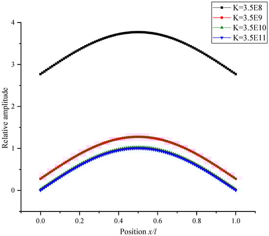
Figure 7.
Vibration modes of the rail beam with different supporting stiffnesses.
Substituting Equation (20) into Equation (18) yielded:
Multiplying both sides of Equation (21) by and integrating them from 0 to , one provided:
where represents the current longitudinal position of the grinding wheel with respect to the rail beam. Since the workpiece velocity was far less than the abrasive wheel peripheral velocity, the workpiece feeding process could be regarded as a quasi-static process. Therefore, the rail beam vibration equation at different longitudinal positions where the grinding wheel ground could be acquired.
Set
where:
The magnitude of was approximately , which was relatively small. The natural frequencies at different supporting stiffnesses with and without the term are demonstrated in Figure 8. With the increase in the support stiffness, the natural frequency of the rail beam increased, showing a trend of slow increase, followed by a fast increase, and finally, stability. The difference in the natural frequency between the model with and without term was always less than 1.5% of the natural frequency. Hence, for the simplicity of calculation, the term was ignored in the next analysis.
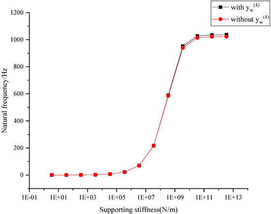
Figure 8.
Natural frequency at different supporting stiffnesses with and without .
.
Considering the material damping of the rail beam and the damping of both ends of the support, a damping term was introduced into Equation (23), whose value could be calculated from the damping ratio and measured by the frequency response function:
where is the damping ratio measured by the frequency response function.
Hence, the equivalent dynamic model of the rail could be expressed as Equation (28):
4. Analysis of Grinding Stability
4.1. Mechanism of the Grinding Chatter
In grinding, the interaction interface between the dynamic models of the grinding wheel and the rail beam grinding system was the grinding force. As shown in Figure 9, relative vibrations occurred between the grinding wheel and workpiece by the action of the grinding force, which resulted in a change in the actual grinding depth , which affected the grinding force and then affected the relative vibration of the grinding wheel and workpiece. The grinding force, actual grinding depth and relative vibration of the grinding wheel and workpiece were coupled. The energy transfer relationship of the whole grinding system was as follows: the grinding force worked on the grinding wheel and workpiece to transfer the energy of the machine tool to the grinding system, and the damping of the grinding wheel and workpiece consumed energy. When the energy input to the system was greater than the energy dissipated, the mechanical energy of the system increased, and grinding chatter occurred. In this section, the stability limit conditions of rail beam grinding were solved from the perspective of the frequency domain of the system.
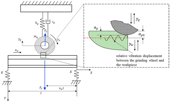
Figure 9.
Grinding system of rail beam.
To acquire the characteristics of the frequency domain of the grinding system, the Laplace transformation of Equations (16), (17) and (28) were taken:
Set
where represents the transfer function of and ; represents the transfer function of and , and represents the transfer function of and .
The system control block diagram is shown in Figure 10, and the characteristic equation of the beam grinding system was obtained by Equations (29)–(31).
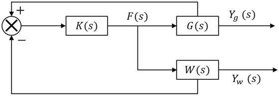
Figure 10.
Rail beam grinding system control block diagram.
When , the system was in a critical state. Thus,
Hence,
where:
When solving Equations (37) and (38) with the frequency around the natural frequency of the system, the relationship between the coefficient of the grinding force in the Y direction and spindle speed could be acquired, that is, a stability limit curve, which was similar to lobes. According to the relationship between the coefficient of the grinding force in the Y direction and the depth of cut , the limit stability curve could be expressed as “ versus ”, as illustrated in Figure 11. The grinding under the parameters in the area below the curve was stable, which meant that the chatter would not evolve; in contrast, chatter could develop under the grinding parameters in the area above the curve.
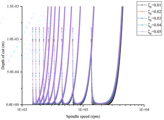
Figure 11.
The stability limit curves with different damping ratios of the grinding wheel.
4.2. Influence of the Dynamic Characteristics of the System on the Grinding Stability
The damping ratio between the grinding wheel and workpiece could reflect the dissipation capacity of the system to mechanical energy and affect the stability of the system. First, the stability limit curves of the system under different wheel damping ratios and different workpiece damping ratios were calculated. Figure 11 shows the stability limit curve at the mid-span position of the rail beam with the damping ratio of the workpiece at 2% and the wheel damping ratio at 1%, 2%, 3%, 4% and 5%. With the increase in the wheel damping ratio, the stability curve moved in the direction of the increasing grinding depth, and the movement amplitude of the “tip” in each lobe was significantly higher than that of the “blade edge” in each lobe, indicating that with the increase in the wheel damping ratio, the stability of the system could be improved. Figure 12 shows the stability limit curve at the mid-span position of the rail beam with the damping ratio of the grinding wheel at 2% and the workpiece damping ratio at 1%, 2%, 3%, 4% and 5%. With the increase in the workpiece damping ratio, the stability curve moved in the direction of increasing grinding depth, but the movement amplitude was smaller than that of the stability curve when the grinding wheel damping ratio was different. The results showed that the stability of the system increased with the increasing workpiece damping ratio. At the same time, it could be seen that the influence of the workpiece damping ratio on the system’s stability was less than that of the grinding wheel damping ratio.
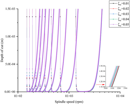
Figure 12.
The stability limit curves with different damping ratios of the workpiece.
From the workpiece vibration Equation (28), the stiffness of the workpiece decreased with increasing distance to the constraint (fastener). According to Figure 7, it could also be seen that the vibration amplitude of the workpiece increased as the distance to the constraint (fastener) increased in the same mode. The stiffness in the rail represented the ability to resist deformation and affected the stability of the system. Therefore, the stability limit curves of different positions (, , , , , and to the constraint) were calculated, as shown in Figure 13. In the calculation, the grinding wheel and workpiece damping were both 2%. With the increasing distance from the constraint, the stability limit curve moved in the direction of the decreasing grinding depth, and the movement amplitude of the “blade edge” was greater than that of the “tip”, indicating that under the same grinding parameters, the stability of the system decreased while increasing the distance from the fastener.
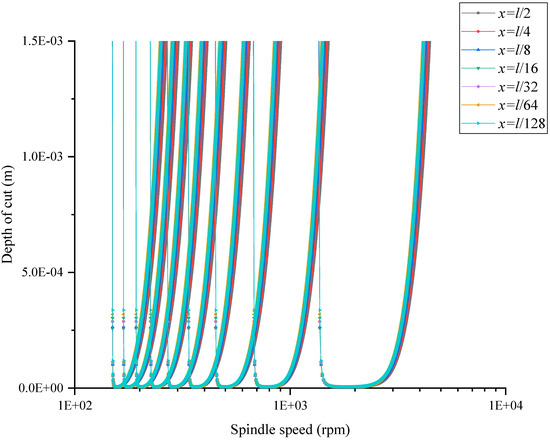
Figure 13.
The stability limit curves at different longitudinal positions of the workpiece.
5. Experimental Validation
5.1. Experimental Setup
The grinding experiments were conducted on a high-precision surface grinder (Blohm Profimat MT-408, Blohm Jung GmbH, Hamburg, Germany). This system is shown in Figure 14. A corundum abrasive wheel with a diameter of 400 mm was adopted in the experiments, whose grain size was 40#. The workpiece (rail beam) was fixed on the workbench by two rail fastenings at the ends of the rail. The tri-axis accelerometers were installed in the mid-span of the rail by means of magnetic absorption to measure the vibration signal in the vertical direction (Y direction). The vibration signal was collected by a data acquisition system (DAQ), which consisted of a charge amplifier, signal conditioning apparatus and personal computer.
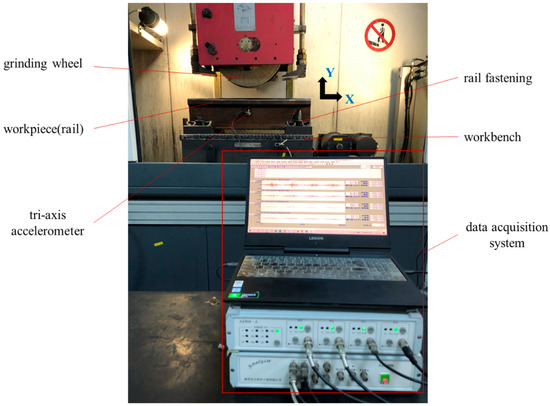
Figure 14.
Rail beam grinding and measurement system.
The ranges of the spindle speed and depth of cut were set to 1250–3500 rpm and 0.01–0.3 mm, respectively. Twenty-five groups of single-factor experiments were carried out, and the grinding parameters are shown in Table 3.
Table 3.
Grinding parameters.
5.2. Results of the Experiment
According to the test results of the system frequency response function (Table 1), the grinding stability limit curve of the experimental system at the rail mid-span position was calculated, as shown in Figure 15. If the grinding parameters (grinding depth and spindle speed) below the curve were selected, the grinding process would be stable. If grinding parameters above the curve were selected for grinding, the grinding process was unstable; that is, the grinding chatter appeared. The grinding parameter corresponding to point A (located below the curve) was selected to carry out the experiment: the spindle speed was 1500 rpm, and the grinding depth was 0.01 mm. After grinding, the workpiece surface was photographed. It was found that the workpiece surface was smooth, declaring that the grinding process was stable. The grinding parameters corresponding to point B (located above the curve) were selected: the spindle speed was 1500 rpm, and the grinding depth was 0.1 mm. The grinding experiment was conducted to observe the surface of the workpiece after grinding. It was found that there were chatter marks in the direction perpendicular to the workpiece feed; that is, grinding chatter occurred.
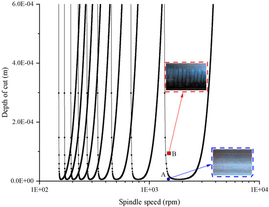
Figure 15.
Grinding stability limit curve at the rail mid-span position of the experimental system.
The frequency spectrum of the vibration signals collected in two groups of experiments at point A and point B were analyzed, as illustrated in Figure 16. In the two groups of experiments, the grinding wheel speed was 1500 rpm, and the corresponding rotation frequency was 25 Hz. In the frequency spectrum of the stable grinding state (point A), the energy concentrated at approximately 751.1 Hz and 925.4 Hz, both of which were multiples of the rotation frequency, indicating that the vibration was forced vibration. By contrast, in the spectrum of the chatter state (point B), the energy was approximately 525.3 Hz, 751.1 Hz and 1017.3 Hz, and the maximum energy was 1017.3 Hz. Both 525.3 Hz and 751.1 Hz were multiples of the rotation frequency, while 1017.3 Hz was not a multiple of the rotation frequency and was larger than the dominant natural frequency of the grinding wheel (1007.55 Hz), indicating that 1017.3 Hz was the chatter frequency, which is consistent with Liu’s study [31]. For chatter grinding, the vibration was a mixture of forced vibration and self-excited vibration.
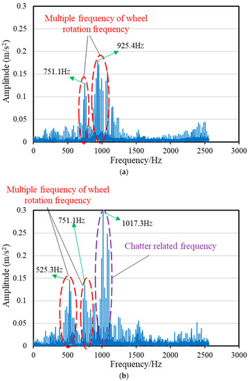
Figure 16.
Frequency spectrum of vibration (acceleration): (a) Point A, (b) Point B.
The results of other experiments are shown in Figure 17, where  represents the experiment groups in which chatter developed and
  represents the experiment groups without chatter. From Figure 17, only near the lobe curve was there a small error between the experimental and calculated results with the model. This error could be attributed to the simplifying assumptions of the model.
represents the experiment groups in which chatter developed and represents the experiment groups without chatter. From Figure 17, only near the lobe curve was there a small error between the experimental and calculated results with the model. This error could be attributed to the simplifying assumptions of the model.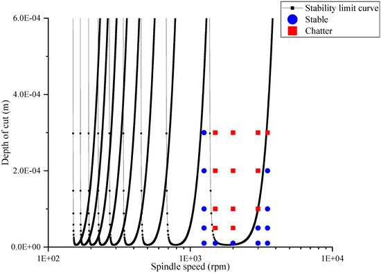
Figure 17.
Experimental results demonstrated the stability limit curve.
6. Conclusions
The grinding chatter of the beam surface was investigated by analyzing the dynamics of a single abrasive grain. The chatter model considering the stiffness variation along the longitudinal direction was proposed based on the dynamic grinding force and Timoshenko beam model. Rail beam grinding experiments were carried out to identify the chatter characteristics. Several conclusions could be drawn:
- (1)
- The stability limit curves at any position in the longitudinal direction could be acquired from the chatter model, which provided valuable information on chatter avoidance for the industry. With the same grinding parameters, the stability of the beam grinding system decreased with increasing distance from the fastener.
- (2)
- The stability of the system increased with the increased damping ratio of the grinding wheel and workpiece, and the influence of the workpiece damping ratio on the system stability was less than that of the grinding wheel damping ratio.
- (3)
- From the grinding experiments, chatter marks were observed on the surface after grinding in the chatter state. Compared to the stable vibration signal, the energy of the chatter signal was mainly concentrated at the chatter frequency, which was higher than the natural frequency of the grinding wheel.
Author Contributions
Conceptualization, H.W.; Data curation, H.W.; Investigation, H.W. and Z.Y.; Methodology, H.W. and Z.Y.; Writing—original draft, H.W.; Writing—review and editing, H.W. and Z.Y. All authors have read and agreed to the published version of the manuscript.
Funding
This research was funded by the National Natural Science Foundation of China under grant number 52075323 and U20A20284.
Institutional Review Board Statement
Not applicable.
Informed Consent Statement
Not applicable.
Data Availability Statement
Data sharing not applicable.
Acknowledgments
The authors acknowledge support from the National Natural Science Foundation of China under Grant Nos. 52075323 and U20A20284.
Conflicts of Interest
The authors declare that they have no known competing financial interests or personal relationships that could have appeared to influence the work reported in this paper.
References
- Zhao, D.; Liu, J.; Wu, C.Q. Stability and local bifurcation of parameter-excited vibration of pipes conveying pulsating fluid under thermal loading. Appl. Math. Mech. 2015, 36, 1017–1032. [Google Scholar] [CrossRef]
- Wang, W.K.; Wan, M.; Zhang, W.H.; Yang, Y. Chatter detection methods in the machining processes: A review. J. Manuf. Process. 2022, 77, 240–259. [Google Scholar] [CrossRef]
- Zhang, P.; Gao, D.; Lu, Y.; Kong, L.; Ma, Z. Online chatter detection in milling process based on fast iterative VMD and energy ratio difference. Measurement 2022, 194, 111060. [Google Scholar] [CrossRef]
- Hou, Y.; Yao, P.; Zhang, H.; Liu, X.; Liu, H.; Huang, C.; Zhang, Z. Chatter stability and surface quality in milling of unidirectional carbon fiber reinforced polymer. Compos. Struct. 2021, 271, 114131. [Google Scholar] [CrossRef]
- Altintas, Y.; Weck, M. Chatter Stability of Metal Cutting and Grinding. CIRP Ann. 2004, 53, 619–642. [Google Scholar] [CrossRef]
- Malkin, S.; Guo, C. Grinding Technology: Theory and Applications of Machining with Abrasives; Industrial Press: New York, NY, USA, 2008. [Google Scholar]
- Chen, Q.; Li, W.; Ren, Y.; Zhou, Z. 3D chatter stability of high-speed micromilling by considering nonlinear cutting coefficients, and process damping. J. Manuf. Process. 2020, 57, 552–565. [Google Scholar] [CrossRef]
- Sun, C.; Niu, Y.; Liu, Z.; Wang, Y.; Xiu, S. Study on the surface topography considering grinding chatter based on dynamics and reliability. Int. J. Adv. Manuf. Technol. 2017, 92, 3273–3286. [Google Scholar] [CrossRef]
- Sun, C.; Liu, Z.; Lan, D.; Duan, J.; Xiu, S. Study on the influence of the grinding chatter on the workpiece’s microstructure transformation. Int. J. Adv. Manuf. Tech. 2018, 96, 3861–3879. [Google Scholar] [CrossRef]
- Zhang, Y.; Fang, C.; Huang, G.; Xu, X. Modeling and simulation of the distribution of undeformed chip thicknesses in surface grinding. Int. J. Mach. Tools Manuf. 2018, 127, 14–27. [Google Scholar] [CrossRef]
- Ding, W.; Dai, C.; Yu, T.; Xu, J.; Fu, Y. Grinding performance of textured monolayer CBN wheels: Undeformed chip thickness nonuniformity modeling and ground surface topography prediction. Int. J. Mach. Tools. Manuf. 2017, 122, 66–80. [Google Scholar] [CrossRef]
- Zhang, W.; Zhang, P.; Zhang, J.; Fan, X.; Zhu, M. Probing the effect of abrasive grit size on rail grinding behaviors. J. Manuf. Process. 2020, 53, 388–395. [Google Scholar] [CrossRef]
- Inasaki, I.; Karpuschewski, B.; Lee, H.S. Grinding Chatter–Origin and Suppression. CIRP Ann. 2001, 50, 515–534. [Google Scholar] [CrossRef]
- Álvarez, J.; Barrenetxea, D.; Marquínez, J.; Bediaga, I.; Gallego, I. Effectiveness of continuous workpiece speed variation (CWSV) for chatter avoidance in throughfeed centerless grinding. Int. J. Mach. Tools Manuf. 2011, 51, 911–917. [Google Scholar] [CrossRef]
- Barrenetxea, D.; Marquinez, J.I.; Bediaga, I.; Uriarte, L. Continuous workpiece speed variation (CWSV): Model based practical application to avoid chatter in grinding. CIRP Ann. 2009, 58, 319–322. [Google Scholar] [CrossRef]
- Hahn, R.S. On the theory of regenerative chatter in precision-grinding operations. Trans. Am. Soc. Mech. Eng. 1954, 76, 593–597. [Google Scholar] [CrossRef]
- Snoeys, R.; Brown, D. Dominating parameters in grinding wheel—And workpiece regenerative chatter. Adv. Mach. Tool Des. Res. 1970, 325–348. [Google Scholar]
- Thompson, R.A. On the doubly regenerative stability of a grinder. J. Eng. Ind. 1974, 96, 275–280. [Google Scholar] [CrossRef]
- Thompson, R.A. On the doubly regenerative stability of a grinder: The combined effect of wheel and workpiece speed. J. Eng. Ind. 1977, 99, 237–241. [Google Scholar] [CrossRef]
- Thompson, R.A. On the doubly regenerative stability of a grinder: The mathematica analysis of chatter growth. J. Eng. Ind. 1986, 108, 83–92. [Google Scholar] [CrossRef]
- Thompson, R.A. On the doubly regenerative stability of a grinder: The effect of contact stiffness and wave filtering. J. Eng. Ind. 1992, 114, 53–60. [Google Scholar] [CrossRef]
- Li, H.; Shin, Y.C. Wheel regenerative chatter of surface grinding. J. Manuf. Sci. Eng. 2005, 128, 393–403. [Google Scholar] [CrossRef]
- Li, H.; Shin, Y.C. A time-domain dynamic model for chatter prediction of cylindrical plunge grinding processes. J. Manuf. Sci. Eng. 2006, 128, 404–415. [Google Scholar] [CrossRef]
- Li, H.; Shin, Y.C. A study on chatter boundaries of cylindrical plunge grinding with process condition-dependent dynamics. Int. J. Mach. Tools Manuf. 2007, 47, 1563–1572. [Google Scholar] [CrossRef]
- Chung, K.W.; Liu, Z. Nonlinear analysis of chatter vibration in a cylindrical transverse grinding process with two time delays usinganonlinear time transformation method. Nonlinear Dyn. 2011, 66, 441–456. [Google Scholar] [CrossRef]
- Yan, Y.; Xu, J.; Wiercigroch, M. Regenerative chatter in self-interrupted plunge grinding. Meccanica 2016, 51, 3185–3202. [Google Scholar] [CrossRef]
- Yan, Y.; Xu, J.; Wiercigroch, M. Regenerative and frictional chatter in plunge grinding. Nonlinear Dyn. 2016, 86, 283–307. [Google Scholar] [CrossRef]
- Yan, Y.; Xu, J.; Wiercigroch, M. Regenerative chatter in a plunge grinding process with workpiece imbalance. Int. J. Adv. Manuf. Technol. 2017, 89, 2845–2862. [Google Scholar] [CrossRef]
- Koro, K.; Abe, K.; Ishida, M.; Suzuki, T. Timoshenko beam finite element for vehicle—Track vibration analysis and its application to jointed railway track. J. Rail Rapid Transit 2004, 218, 159–172. [Google Scholar] [CrossRef]
- Timoshenko, S.P. On the correction for shear of the differential equation for transverse vibrations of prismatic bars. Philos. Mag. 1921, 41, 744–746. [Google Scholar] [CrossRef]
- Liu, Y.; Wang, X.; Lin, J.; Kong, X. An adaptive grinding chatter detection method considering the chatter frequency shift characteristic. Mech. Syst. Signal Process. 2020, 142, 106672. [Google Scholar] [CrossRef]
Disclaimer/Publisher’s Note: The statements, opinions and data contained in all publications are solely those of the individual author(s) and contributor(s) and not of MDPI and/or the editor(s). MDPI and/or the editor(s) disclaim responsibility for any injury to people or property resulting from any ideas, methods, instructions or products referred to in the content. |
© 2023 by the authors. Licensee MDPI, Basel, Switzerland. This article is an open access article distributed under the terms and conditions of the Creative Commons Attribution (CC BY) license (https://creativecommons.org/licenses/by/4.0/).