Abstract
The empirical formula is one of the traditional methods used for predicting ground deformation settlement caused by tunnel excavation. Due to its rationality and simplicity, the Peck formula is widely used for predicting surface subsidence. However, due to its limitations, it is necessary to modify it when predicting surface settlement caused by tunnel excavation in different strata. In this paper, a correction formula for the width coefficient of a tunnel surface settlement slot is derived from the Peck formula by taking into account the theory of strata slip cracks. Values are calculated using the correction formula and compared with measured data to verify the effectiveness of the correction formula. The main conclusions are: (1) The position corresponding to the width of the settlement in the Peck curve is the point where the formation is most prone to slip cracking. (2) In the general shallow buried case, the settlement groove width coefficient K and the internal friction angle φ of the ground satisfy the formula K = 1/tan(45° + φ/2 + a) + b, and the values of parameters a and b reflect the average values of the geometric properties of the tunnel based on the measured data. (3) The prediction of the correction formula is consistent with the measured data, and thus the correction formula can be applied to problems related to the stability of shallow buried tunnels.
1. Introduction
Shallow buried tunnels are widely used in areas with good soil conditions. However, with the continuous construction of urban underground transportation systems, excavation of shallow buried tunnels has become increasingly common in areas where it is difficult for geological conditions to meet the requirements for stability of the soil structure near the tunnel. Additionally, during excavation of shallow tunnels, additional stress is generated in the soil, leading to deformation and even failure of the original soil. The soil undergoes complex stresses such as compression, shear, and torsion, resulting in settlement. The mechanism of ground settlement caused by tunnel construction mainly comes from the elastic–plastic deformation of the strata caused by stress release and additional stress on the excavation surface. Surface subsidence may cause displacement and rupture of surrounding pipelines, cracking and collapse of road surfaces, and damage to inclined structures of surrounding buildings, posing a great threat to people’s lives and the safety of properties. Therefore, accurate prediction of surface settlement, targeted improvement of construction techniques, optimization of construction parameters, and maintenance of ground settlement values within a safe range can greatly improve construction safety.
Surface settlement prediction is an important area of tunnel excavation research and has been studied by many domestic and foreign scholars [1,2,3]. The Peck formula and its various empirical corrections are some of the most widely used methods. Peck [4] considered that the shape of a lateral settlement trough of a tunnel approximates a normal distribution and proposed an empirical formula for ground settlement. Tang et al. [5] used Peck’s formula to study surface displacement in the construction of group pipe jacking using the pipe curtain method and proposed empirical formulas for the settlement slot width coefficient and ground loss rate during pipe jacking; these formulas can be applied to predict surface settlement. Additionally, Tang et al. [6] modified Peck’s formula and studied tunnel surface settlement in low-permeability soils. Wang et al. [7] used Peck’s formula to fit tunnel surface settlement data obtained in Beijing and discussed the effects of construction methods, tunnel burial depth, support stiffness, and other factors, on the empirical parameters of the formula and then gave a correction formula for the empirical parameters. Han et al. [8] suggested values for the empirical parameters in the Peck formula by studying tunnel surface settlement data obtained in Beijing and Shanghai and pointed out the limitations of the applicability of the Peck formula to ultra-shallow buried tunnels. In addition, many other predictive methods have been studied in detail. The stochastic medium theory proposed by Litwinszyn [6], which is based on coal mine excavation, is based on the assumption that the ground settlement trough is caused by uniform convergence of the tunnel and can be used to calculate the surface settlement caused by the tunnel excavation. Li et al. [9,10] analyzed the influence of shear stress on soil settlement deformation through direct shear tests and numerical simulation. Han et al. [11] further studied the deformation pattern of uneven convergence of a tunnel and proposed a predictive model for the settlement of tunnels with various section shapes. Lu et al. [12] used a Fourier series to model the deformation of a shallow buried tunnel section and proposed a method for combining section convergence values to determine ground displacement. Wu et al. [13] proposed a machine learning method for modeling soil particle constitution and predicting settlement deformation using the tunnel soil constitutive model.
As shown in the above studies, predictive methods that consider various factors, including geological conditions, construction techniques, and tunnel cross section shapes, are well known. However, there is limited research on the effect of strata slip cracks on surface settlements. Strata slip cracks are geological formations that occur when layers of rock or soil move past each other due to pressure and other forces. Strata slip cracks are often induced by tunneling in landslide areas [14]. If a strata slip crack is not correctly identified during the tunnel survey and design process, it may affect tunneling efficiency [15] and may even endanger the safety of the tunnel [16]. Therefore, focus was placed on the analysis of ground slip cracking prior to tunnel excavation. The common method for analyzing the effect of stratigraphic slip fractures is numerical simulations; however, due to the influence of geological conditions and the lack of human knowledge of objective facts, simulation results often do not correlate with the real situation [17].
Damage to strata slip cracks usually affects the surface settlement, and with increasing surface settlement, the impact on engineering safety is not negligible, thus it is important to explore the impact of strata slip crack on surface settlement [18,19]. Recently, settlement monitoring equipment have been gradually used in the tunnel excavation process. The actual state of the current ground settlement can be determined by monitoring the settlement. Many experts have analyzed ground deformation using settlement monitoring data [20,21,22].
Although many scholars have proposed prediction methods and failure theories for surface settlement of shallow buried tunnels, there is little research on the consideration of geological sliding cracks in the Pick formula. Therefore, the theory of strata slip cracks was applied to the analysis of ground deformation and the prediction method was applied to shallow buried tunnel construction. We proposed a correction formula for the width coefficient of the settlement slot and compared the predicted results with measured data to verify the proposed correction formula.
2. Methodology
2.1. Theory of Strata Slip Cracks
Shallow buried tunnels generally occur due to small burial depths and deviations in surrounding rock conditions. Therefore, after tunnel excavation, the self-bearing capacity of the surrounding rock is limited and cannot form a stable supply, resulting in the occurrence of landslides. This not only endangers the safety of the construction, but also has an adverse impact on ground structures in severe cases. In shallow buried tunnel collapse accidents, a clear sliding failure surface is usually formed on both sides of the tunnel and the overlying surrounding rock, which is called the sliding fracture surface. According to the conclusions of Wang et al. [23], the slip fracture surface is simplified to an oblique straight line and the angle between the slip fracture surface and the horizontal surface is defined as the slip fracture angle β.
As shown in Figure 1, the oblique lines on both sides of the tunnel in the figure represent the simplified sliding surface, which is the connecting line between the tunnel wall corner and the critical displacement point of the surface on that side. The fracture angle corresponds to sliding surface β. It can be obtained using the trigonometric function. Here, H represents the thickness of the soil covering the upper part of the tunnel, which is the burial depth of the tunnel; h represents the height of the tunnel; L represents the horizontal distance between the critical displacement point on the surface and the corner of the tunnel wall on that side, which is correlated with the geometric parameters of the tunnel, surrounding rock conditions, and construction methods.
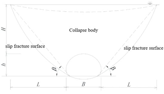
Figure 1.
Vertical view of the strata slip crack.
For classic loose accumulation bodies, the slip angle calculated by Terzaghi and Rankine earth pressure is 45° + φ/2. Obviously, for complex surrounding rock situations, this idealized calculation cannot accurately meet the actual engineering needs. Yi et al. [24] proposed a method for deriving slip angle, taking into account tunnel geometric parameters, as follows:
where K1 is the geometric shape parameter of the tunnel, which is determined by the surrounding rock coverage ratio (H/D) and the cross-sectional flatness ratio (h/D), and K0 is the side pressure coefficient. In most shallow burial cases, K0 < 1, which means that tan (2θ) > −cot φ, β > 45° + φ/2.
The formula shows that the shallower the burial depth and the larger the span of a tunnel, the more obvious the damage to the stratum. The slip crack angle can exceed the result obtained using the traditional method (i.e., 45° + φ/2) by more than 15°. The results of the classical slip crack angle and the range of the new slip crack angle for each soil (rock) type based on the classical Terzaghi theory and the analysis of new slip crack angles by Yi et al., are shown in Table 1.

Table 1.
Recommended values of the shear strength of soils and weathered rocks.
The area of the line between the slip crack surface, the ground surface, and the tunnel sidewalls is considered the collapse body, as shown in Figure 2. The strata within the collapse body are the main areas where deformations occur. The larger the friction angle within the stratum, the larger the slip crack angle, and the smaller the range of the collapsed body, the smaller the influence of the tunnel on the deformation of the stratum.
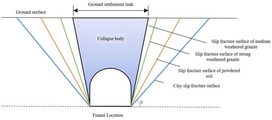
Figure 2.
Range of influence of slip fracture surface parameters on ground settlement.
2.2. Correction of the Surface Settlement Prediction Equation Considering Strata Slip Cracks
2.2.1. Surface Settlement Pattern
At present, the empirical formula for predicting surface settlement during shield tunnel construction mainly utilizes on-site engineering measured surface settlement data and a series of strata deformation calculation methods developed based on the Peck empirical formula. In 1969, Peck [1] proposed an empirical formula for predicting surface settlement caused by tunnel construction. Assuming that the soil is not drained and consolidated, it is believed that the cross-sectional settlement curve of the ground caused by shield tunnel construction is a Gaussian curve and the volume of ground loss can be represented by the volume of settlement slots. The Peck empirical formula for predicting surface settlement is proposed as follows:
According to Peck’s theory, the main cause of soil deformation is soil loss during the tunnel excavation process. The surface transverse settlement trough is normally distributed and its volume is equal to the soil loss volume. The formula for estimating lateral ground settlement caused by tunnel construction is:
where Smax is the surface settlement directly above the tunnel axis, the theoretical maximum surface settlement value; y is the horizontal distance from the ground point corresponding to the tunnel centerline to the calculation point; and i is the settlement trough width, the horizontal distance from the tunnel axis to the inflection point of the settlement curve.
Accurately quantifying the parameters in the Peck formula is the determining factor in accurately predicting surface subsidence using this formula. A large number of domestic and foreign scholars have conducted in-depth research on the empirical parameters of the empirical Peck formula. New BM [25] analyzed the measured values of maximum surface settlement and settlement trough width and volume for clayey, backfill, and sandy soils in the UK and concluded that the tunnel burial depth greatly affects the settlement trough width. The relationship between tunnel burial depth and settlement trough width is defined as:
where i is the settlement slot width, K is the settlement slot width coefficient, and Z is the tunnel burial depth.
Han et al. [11] summarized the suggested preliminary values of the settlement trough width coefficient caused by tunnel excavation in some areas of China: K is 0.50 in Shanghai, 0.60–0.80 in Guangzhou and Shenzhen, and 0.30–0.60 in Beijing, where the soil conditions are relatively complex.
2.2.2. Derivation of the Correction Formula
The functional form of Peck’s formula is essentially a Gaussian distribution curve, and derivation of the function of Peck’s formula yields:
where is the rate of change of curve S in Equation (3).
From Formula (5), the rate of change of the value of stratum settlement along the y direction is largest when y = i. This point is the most obvious point of uneven ground settlement and the most likely point of stratum slip crack. As the stratum deepens, the value of the settlement trough width gradually decreases and the most dangerous slip-cracking point gradually gets closer to the center of the tunnel. The most dangerous slip-cracking point of each stratum is correlated with a smooth curve, which constitutes the most dangerous slip-cracking surface of the tunnel.
As shown in Figure 3, when the dimensional parameters of the tunnel are disregarded and only the depth of tunnel burial is taken into account, the relationship between the sink width and the slip crack angle is:
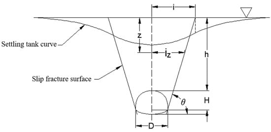
Figure 3.
Relationship between strata slip crack surface and settlement trough.
According to the formula developed by the British scholar Mair [26] and others, iz = (h − z)/tan θ, the following equation can be obtained:
where h is the tunnel burial depth, iz is the depth of at the stratum sink width, θ is the tunnel slip crack angle, K is the depth of z at the sink width coefficient, and φ is the internal friction angle of the stratum’s geotechnical body.
Based on the above analysis, and considering the tunnel dimension parameters, i.e., height H and span D, Equations (6) and (7) take the following forms:
where H is the tunnel height, D is the tunnel span, and h is the distance from the top of the tunnel to the ground surface. Excluding the case of super-shallow burial, it is generally considered that the depth of burial of the tunnel is greater than the height of the tunnel, i.e., (h + H)/h ≈ 1. Only when considering the width coefficient of the settlement trough on the surface, i.e., z = 0, is Equation (9) simplified as follows:
Since the actual slip crack angle in shallow buried tunnels is generally larger than that calculated by the conventional method (45° + φ/2), it is assumed that the magnitude of the actual slip crack angle is θ = 45° + φ/2 + a and D/2h = b. Kz is then transformed into a function of the internal friction angle φ of the soil layer as follows:
where a and b are parameters. The size of a is determined by the formation slip fracture angle, which indicates the part of the actual formation slip fracture angle that is larger than the value calculated by the conventional method, and the size of b is determined by the overburden-to-span ratio of the surrounding rock.
3. Results
3.1. Fitting Real Data
To verify the applicability of the proposed correction formula, 18 sets of publicly available measured data for ground settlement caused by the construction of shallow buried tunnels across the world were collected and analyzed in this study. Most of the data were collected during construction of urban subway tunnels; however, some shallow buried tunnels were excavated in the soil for other purposes, such as to lay sewage pipes. The main focus of this study was to fit the measured ground settlement curve using Peck’s formula to obtain the value of i and then to calculate the value of K according to O’Reilly’s formula, and to obtain the average internal friction angle of the overlying and crossing soil layers of the tunnel according to the weighted average of the soil distribution. The results are shown in Table 2.

Table 2.
Results of Gaussian curve fitting of ground deformation caused by construction of shallow buried tunnels.
Since burial depths and soil distribution can change in different sections of the same project, multiple results may be obtained by fitting data for the same project, for example, Shanghai Tunnel Line 2 and Nanjing Metro Line 1 in Table 2.
The data in Table 2 are fitted based on the proposed correction formula to obtain the fitted curve of K versus φ, as shown in Figure 4.
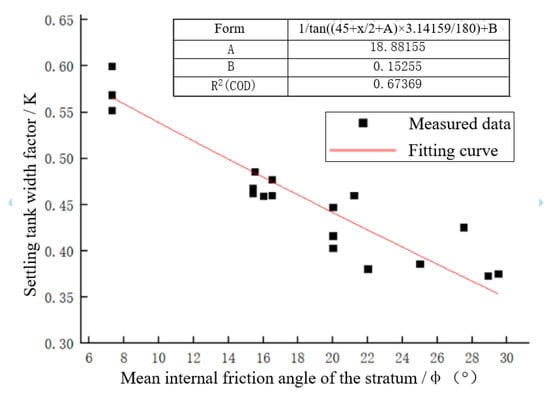
Figure 4.
Fitting curve for the width coefficient of the settlement tank.
As shown in Figure 4, the R2 = 0.67 of the fitted curve and the relationship between K and φ can satisfy the proposed correction formula, indicating that the model and formula established in this paper have some applicability. When φ is between 5° and 30°, the relationship between K and φ is roughly linear, i.e., K decreases linearly as φ increases. The values of parameters a and b reflect the engineering characteristics of different tunnels. The average value of parameter a is 18.88, which means that the actual slip crack angle of the shallow buried tunnel strata exceeds the results calculated by the conventional method (i.e., 45° + φ/2) by approximately 18.88°, which is also consistent with the results of the new slip crack angle formula derived by Yi et al. [24] and verifies the validity of the modified formula from another perspective. The average value of parameter b is 0.15, reflecting an average overburden-to-span ratio of approximately 3 in the collected tunnel engineering data.
There is a certain dispersion between the measured data and the fitted curves in this paper because the ground slip angle is also influenced by the tunnel cover-to-span ratio, the sagittal-to-span ratio, and geological and construction parameters. When the selected tunnel geometry parameters vary considerably, the fitted parameter values a and b change accordingly.
3.2. Instance Verification
A subway tunnel in Shenzhen is used as an example to verify the correction formula. The typical section of the tunnel has a height of 12.7 m and a span of 8.1 m, with the top arch 5.6 m from the surface. The detailed parameters of the section are shown in Figure 5. First, the Peck formula is fitted to the surface settlement results after tunnel construction.
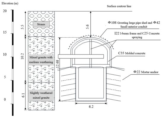
Figure 5.
Subway tunnel section parameters (unit: m).
The results of fitting the Peck curve to the results of the numerical simulation are shown in Figure 6. The results show that the surface deformation pattern during the tunnel construction period conforms to the normal distribution curve, with a maximum surface settlement value of 3.1 mm and a settlement trough width i = 4.7 m. When the geometric parameters of the tunnel are input in the correction formula, the tunnel slip crack angle θ is found to be 84°, exceeding the value of 45° + φ/2 (where φ is taken as 34°) by 22°. It is close to the fitted curve of a = 18.8° and is consistent with the overall sliding characteristics of the overlying strata of the shallow buried tunnel.
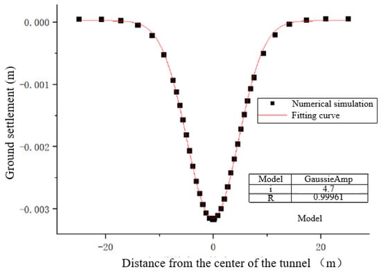
Figure 6.
Fitting curve of surface settlement of the relying project.
In addition, based on various methods of calculating the surrounding rock pressure, including Proctor’s theory and Terzaghi theory, the modified model proposed in this paper can be applied to the shallow buried cavern stability problem. Therefore, the results of the modified formula are substituted into the surrounding rock pressure formula proposed by Yu Li et al. [39]:
where Pq is the vertical pressure, Pe is the horizontal pressure, λ is the lateral pressure coefficient, h is the distance from the top arch of the tunnel to the ground, K is the tunnel vector-to-span ratio, and β is the slip crack angle.
The value of the lateral pressure coefficient λ is 0.304, based on the Highway Tunnel Design Code. The results obtained from the modified model are added to Equations (12) and (13) to obtain a vertical pressure of 144.25 kPa and a lateral pressure of 42.85 kPa. Then, the simplified formula in the Highway Code is used to calculate a vertical pressure of 99.48 kPa and a lateral pressure of 17.02 kPa. The results show that the pressure value calculated using the modified model is larger than that of the specification and has a certain safety reserve.
4. Conclusions
By considering the characteristics of stratum slip fractures, the influence of slip fracture surface parameters on stratum deformation is studied, the theoretical formula for the width of the surface settlement trough is modified, and the applicability of the modified formula is verified by comparing it with measured data. The main conclusions obtained are as follows:
- The location corresponding to the width of the settlement trough in the Peck curve is the point where the most obvious uneven settlement of the ground surface occurs and the point where slip cracking of the strata is most likely to occur. The most dangerous slip-crack points of each stratum are connected by a smooth curve, which constitutes the most dangerous slip-crack surface of the tunnel.
- By considering the ground slip crack and the tunnel dimension parameters, an equation is derived for the width coefficient K of the sinkhole and the internal friction angle φ of the soil. The equation is considered to satisfy the equation K = 1/tan (45° + φ/2 + a) + b in the general shallow burial case, and the values of parameters a and b reflect the average values of the geometric properties of the tunnel project based on the measured data.
- The formula derived in this article was evaluated using measured data of surface settlements caused by tunnel excavation both domestically and internationally. The width coefficient K of the settlement groove varied with the internal friction angle of the ground φ. The increase showed an approximate linear decreasing trend and the fit was good. Finally, the improved model was used to calculate the pressure of the surrounding rocks.
Author Contributions
Methodology, X.X.; Software, H.J.; Validation, X.X. and H.J.; Formal analysis, H.J. and S.H.; Investigation, J.Z. and S.H.; Resources, S.H.; Data curation, J.Z.; Writing—original draft, Z.M.; Writing—review & editing, Z.M. and X.W. All authors have read and agreed to the published version of the manuscript.
Funding
This work was supported by Huaneng Group Headquarters Technology Project (Grant No. HNKJ21-H33).
Data Availability Statement
The data are not publicly available due to restrictions of privacy.
Conflicts of Interest
The authors declare no conflict of interest.
References
- Jin, D.; Yuan, D.; Li, X.; Zheng, H. Analysis of the settlement of an existing tunnel induced by shield tunneling underneath. Tunn. Undergr. Space Technol. 2018, 81, 209–220. [Google Scholar] [CrossRef]
- Fu, J.; Yang, J.; Zhang, X.; Klapperich, H.; Abbas, S.M. Response of the ground and adjacent buildings due to tunnelling in completely weathered granitic soil. Tunn. Undergr. Space Technol. 2014, 43, 377–388. [Google Scholar] [CrossRef]
- Li, F.-m.; Chen, G.-x. Study on deformation characteristics of ground surface settlement during shield tunnel construction of river floodplain in Nanjing. J. China Railw. Soc. 2020, 42, 155–160. [Google Scholar]
- Peck, R.B. Deep excavations and tunneling in soft ground. In Proceedings of the 7th International Conference on Soil Mechanics and Foundation Engineering, Mexico City, Mexico, 1969; Sociedad Mexicana de Mecanica: Mexico City, Mexico, 1969; pp. 225–290. [Google Scholar]
- Tang, Z.; Wang, H.; Sun, D.; Zhang, X. Surface displacement during pipe roof construction of pipe-jacking group with large section. Rock Soil Mech. 2022, 43, 1933–1941. [Google Scholar]
- Wang, J.C.; Zhang, D.L.; Zhang, C.P.; Fang, Q.; Su, J.; Du, N.Q. Deformation of Existing Tunnels Induced by Excation of New Shallow Tunnel in Beijing. Chin. J. Rock Mech. Eng. 2014, 33, 947–956. [Google Scholar]
- Shao, L.; Li, C.; Ni, Y.; Meng, Q.; Li, P. Numerical simulation study on ground settlement of underground tunnel caused by vehicle load. Int. J. Res. Eng. Sci. 2022, 10, 533–541. [Google Scholar]
- Tang, X.; Liang, J.; Liu, W.; Ye, Y.; Gan, P.; Zhao, W.; Yu, Y. Modification of Peck Formula to Predict Ground Surface Settlement of Twin Tunnels in Low Permeability Soil. Adv. Civ. Eng. 2021, 2021, 1–13. [Google Scholar] [CrossRef]
- Han, X.; Li, N.; Standing Jamie, R. An adaptability study of Gaussian equation applied to predicting ground settlements induced by tunneling in China. Yantu Lixue (Rock Soil Mech.) 2007, 28, 23–28. [Google Scholar]
- Litwiniszyn, J. Fundamental principles of the mechanics of stochastic media. In Proceedings of the 3rd Conference on Theoretical Applied Mechanics, Kharagpur, India, 24–27 December 1957; pp. 93–110. [Google Scholar]
- Li, Z.; Liu, J.; Xu, R.; Liu, H.; Shi, W. Study of grouting effectiveness based on shear strength evaluation with experimental and numerical approaches. Acta Geotech. 2021, 16, 3991–4005. [Google Scholar] [CrossRef]
- Li, Z.; Liu, J.; Liu, H.; Zhao, H.; Xu, R.; Gurkalo, F. Stress distribution in direct shear loading and its implication for engineering failure analysis. Int. J. Appl. Mech. 2023, 2350036. [Google Scholar] [CrossRef]
- Han, X.; Li, N. A predicting model for ground movement induced by non-uniform convergence of tunnel. Chin. J. Geotech. Eng. 2007, 172, 347–352. [Google Scholar]
- Lu, D.; Kong, F.; Du, X.; Shen, C.; Gong, Q.; Li, P. A unified displacement function to analytically predict ground deformation of shallow tunnel. Tunn. Undergr. Space Technol. 2019, 88, 129–143. [Google Scholar] [CrossRef]
- Wu, M.; Xia, Z.; Wang, J. Constitutive modelling of idealised granular materials using machine learning method. J. Rock Mech. Geotech. Eng. 2023, 15, 1038–1051. [Google Scholar] [CrossRef]
- Tian, X.X.; Song, Z.P.; Zhang, Y.W. Monitoring and reinforcement of landslide induced by tunnel excavation: A case study from Xiamaixi tunnel. Tunn. Undergr. Space Technol. 2021, 110, 103796. [Google Scholar] [CrossRef]
- Venturini, G.; Damiano, A.; Spanò, M.; Gallarà, F.; De Crecchio, L. Productivity Parameters from TBM Excavations of “Pont Ventoux” Hydroelectric Power Plants Tunnels (AEM Torino S.p.A). In Proceedings of the ITA-AITES World Tunnel Congress, Milano, Italy, 2021; Volume 2, pp. 485–492. Available online: https://silo.tips/download/productivity-parameters-from-tbm-excavations-of-pont-ventoux-hydroelectric-power (accessed on 17 May 2023).
- Jiao, Y.Y.; Wang, Z.H.; Wang, X.Z.; Adoko, A.C.; Yang, Z.X. Stability assessment of an ancient landslide crossed by two coal mine tunnels. Eng. Geol. 2013, 159, 36–44. [Google Scholar] [CrossRef]
- Griffiths, D.V.; Huang, J.; Fenton, G.A. Influence of spatial variability on slope reliability using 2-D random fields. J. Geotech. Geoenviron. Eng. 2009, 135, 1367–1378. [Google Scholar] [CrossRef]
- Vassallo, R.; Mishra, M.; Santarsiero, G.; Masi, A. Interaction of a railway tunnel with a deep slow landslide in clay shales. Procedia Earth Planet. Sci. 2016, 16, 15–24. [Google Scholar] [CrossRef]
- Zhang, Y.; Yang, J.; Yang, F. Field investigation and numerical analysis of landslide induced by tunneling. Eng. Fail. Anal. 2015, 47, 25–33. [Google Scholar] [CrossRef]
- Fan, S.; Zhou, Q. Multi-agent system for tunnel-settlement monitoring: A case study in Shanghai. Displays 2021, 69, 102041. [Google Scholar] [CrossRef]
- Wang, Y.F.; Chai, C.M. The statistical characteristic of the break angles by excavating the shallow tunnel. J. Lanzhou Railw. Inst. 1998, 17, 16–20. [Google Scholar]
- Xiao-ming, Y.I.; Dingli, Z.; Tiezheng, P. Mechanism analysis of integral subsidence of upper stratum in urban tunnels. Chin. J. Rock Mech. Eng. 2009, 28, 2860–2867. [Google Scholar]
- New, B.M. Tunnelling induced ground movements: Predicting their magnitude and effects. In Proceedings of the 4th International Conference Held at the University of Wales College of Cardiff, Cardiff, UK, 8–11 July 1991; Pentech Press: London, UK, 1991; pp. 671–697. [Google Scholar]
- Mair, R.J.; Taylor, R.N.; Bracegirdle, A. Subsurface settlement profiles above tunnels in clays. Geotechnique 1993, 43, 315–320. [Google Scholar] [CrossRef]
- Deane, A.P.; Bassett, R.H. The Heathrow Express Trial Tunnel. Geotech. Eng. 1995, 113, 144–156. [Google Scholar] [CrossRef]
- Palmer, J.H.L.; Belshaw, D.J. Deformations and Pore Pressures in the Vicinity of a Precast, Segmented Concrete-Lined Tunnel in Clay. Can. Geotech. J. 1980, 17, 174–184. [Google Scholar] [CrossRef]
- Yi, X.; Rowe, R.K.; Lee, K.M. Observed and Calculated Pore Pressure sand Deformations Induced by an Earth Balance Shield. Can. Geotech. J. 1993, 30, 476–490. [Google Scholar] [CrossRef]
- Lee, K.; Ji, H.; Shen, C.; Liu, J.; Bai, T. Ground Response to the Construction of Shanghai Metro Tunnel-Line 2. Soils Found. 1999, 39, 113–134. [Google Scholar] [CrossRef]
- Yi, H.W. Research on the Disturbance of Soil and Ground Movement Induced by Shield Tunneling; Tongji University: Shanghai, China, 1999. [Google Scholar]
- Li, S.G. Analysis and Numerical Simulation of Surface Settlement Caused by EPB Shield Tunnel Construction; Central South University: Changsha, China, 2006. [Google Scholar]
- Li, Y. Three-Dimensional Numerical Simulation and Experimental Research on the Ground Deformation of Shield Construction; Tianjin University: Tianjin, China, 2004. [Google Scholar]
- Chu, D.F. Study on the Ground Settlement Pattern of Shield Structure Passing through Buildings in the Sanyuanqiao-Liangmahe Station Interval of Beijing Metro Line 10; China University of Geosciences: Beijing, China, 2007. [Google Scholar]
- Heng, C.Y.; Teng, Y.J.; Chen, X.Q. Research on the control of foundation deformation of buildings around metro shield tunnel. Chin. J. Undergr. Space Eng. 2006, 2, 1336–1340. [Google Scholar]
- Zhang, F.J. Shield Construction Through Existing Line Surface Settlement Law and Construction Parameters Optimization; Beijing University of Technology: Beijing, China, 2006. [Google Scholar]
- Guo, Y.H. Study on Settlement Control of Shield Tunnel Underrun the Railroads. Munic. Eng. Technol. 2004, 22, 247–251. [Google Scholar]
- Xu, J.J. Analysis of Ground Settlement Caused by Earth Pressure Balance Shield Construction; Southwest Jiaotong University: Chengdu, China, 2004. [Google Scholar]
- Yi, L.; Lv, C.; Duan, R.Y.; Wang, M.N. Calculation Method for Surrounding Rock Pressure of Shallow Buried Loess Tunnel. China Railw. Sci. 2019, 40, 69–76. [Google Scholar]
Disclaimer/Publisher’s Note: The statements, opinions and data contained in all publications are solely those of the individual author(s) and contributor(s) and not of MDPI and/or the editor(s). MDPI and/or the editor(s) disclaim responsibility for any injury to people or property resulting from any ideas, methods, instructions or products referred to in the content. |
© 2023 by the authors. Licensee MDPI, Basel, Switzerland. This article is an open access article distributed under the terms and conditions of the Creative Commons Attribution (CC BY) license (https://creativecommons.org/licenses/by/4.0/).