Article

An Experimental Study on the Elbow Pressure Drop and Conveying Stability of Pneumatic Conveying for Stiff Shotcrete Based on Response Surface Methodology

1
College of Safety and Environmental Engineering, Shandong University of Science and Technology, Qingdao 266590, China
2
Graduate School of Engineering, Nagasaki University, Nagasaki 852-8521, Japan
3
College of Energy and Mining Engineering, Shandong University of Science and Technology, Qingdao 266590, China
*
Author to whom correspondence should be addressed.
Processes 2023, 11(5), 1574; https://doi.org/10.3390/pr11051574
Submission received: 29 April 2023 / Revised: 15 May 2023 / Accepted: 18 May 2023 / Published: 22 May 2023
(This article belongs to the Section Particle Processes)

Abstract

:
The pressure drop and conveying stability caused by the bend significantly affect the pneumatic conveying process of stiff shotcrete, which is the key to solving the problem of long-distance transportation. In this paper, the effects of different air velocities (32 m/s, 36 m/s, 40 m/s), water-cement ratios (0.1, 0.2, and 0.3), and bending-diameter ratios (4, 12, and 20) on the pressure drop of the elbow R1 and conveying stability R2 are studied using the response surface method. The conveying stability is characterized by the pressure variation coefficient (C.V). The response surface graph aids in the intuitive analysis of the effects of these variables. The results show that the impact of air velocity on R1 and R2 is exceptionally significant, and the interaction of each factor on the response value is analyzed. The response value and the quadratic polynomial regression equation between the various factors are obtained in addition to the flow characteristics of stiff shotcrete under different working conditions. The relationship established by the statistical processing of the experimental results can provide some reference for specifying the pressure loss model of stiff shotcrete.

1. Introduction

The shotcrete support has been widely used in the tunnel excavation project. Commonly, shotcrete is used in the construction of mine shafts, subways, tunnels, hydraulic culverts, and other projects because of its characteristics of no formwork, fast construction speed, simple procedures, and flexibility [1,2,3,4,5,6,7]. The moist spraying process combines the light and fast operation of dry spraying and the low dust production of wet spraying, so it is the more widely used method of spraying in coal mines [8,9]. However, due to wet concrete materials’ unique physical and chemical properties, the pneumatic conveying process is bound to cause significant changes in the conveying speed and pressure drop of stiff shotcrete materials. Therefore, mastering the flow characteristics of stiff shotcrete materials will have an essential influence on further revealing the pneumatic conveying mechanism [10,11,12]. Among them, the elbow structure significantly impacts the pneumatic conveying of wet shotcrete. Due t the complexity of the on-site construction environment, it is inevitable that there will be various elbow structures, resulting in unnecessary pressure loss, which affects the limited conveying distance of the pneumatic conveying of stiff shotcrete. Therefore, conducting in-depth research on elbow pressure drop and conveying stability is necessary.
In the field experiment, Kalman et al. [13,14,15,16,17,18] conducted in-depth research on the transport flow characteristics of various materials based on the pneumatic-transport test platform. They studied the total bending pressure drop in dilute phase flow in detail. A qualitative comparison between blind T and radius bending was made with specific material properties. Tu et al. [19] analyzed the pressure drop and particle velocity and clarified the macroscopic motion characteristics of particles under different bending-diameter ratios. Zhou et al. [20] studied the effects of wall wear, particle breakage, and pressure drop on the elbow using an orthogonal experimental design. They designed a double wall elbow to show erosion characteristics, particle breakage rate, and pressure drop. Ji et al. [21,22] studied the flow characteristics of the spraying materials and pressure loss using field tests and simulation methods. However, due to the simplification of the spraying materials, it is difficult to reflect the fundamental conveying characteristics, and there is no systematic research on the elbow structure. In addition, Kunhanandan and Hamada et al. [23,24] used the response surface method to study the relationship between the density and strength of foam concrete and the characteristics of sustainable concrete. The experimental results proved the accuracy of the response surface method in model prediction.
In terms of numerical simulation, Yu et al. [25,26,27,28,29] reviewed the CFD-DEM modeling and simulation methods of pneumatic conveying, covering the formulation, validation, and application of the proposed mathematical model. Emphasis is placed on the modeling phenomena, such as flow state and transition, pipe wear, and static electricity, and future research directions are discussed. Zhao et al. [30] used the CFD method to study particle wear on multiple elbows and established a relationship between connection length and wear amount. Zhou et al. [31] studied the influence of swirl structure on elbow wear and verified the CFD simulation results with experimental data. Xu et al. [32] simulated and analyzed the abrasion of elbows by pneumatic conveying in addition to the effects of solid volume fraction, the dynamic friction coefficient, the static friction coefficient, and the coefficient of restitution on wear. Christopher et al. [33] used the traditional Eulerian-Lagrangian method to predict the effect of erosion wear and conducted numerical simulation analysis on the wear distribution characteristics. However, this method was too difficult to predict the maximum wear depth accurately. Mechtcherine et al. [34] used the discrete element method to simulate the development and research status of the field of fresh concrete flow and also introduced the existing industrial application of the developed particle model in concrete engineering. At present, it is still difficult to accurately simulate stiff shotcrete materials. Sun et al. [35,36,37,38,39] calibrated the parameters using the response surface method, obtained the parameters used to simulate the shotcrete materials, and preliminarily revealed the flow characteristics of shotcrete horizontal pneumatic conveying using the CFD-DEM method. Although domestic and foreign researchers have made in-depth reports on elbow wear using field tests and simulation methods, there are relatively few studies on the elbow pressure drop and its impact on conveying stability.
Field experiments have studied the influence of air velocity, water-cement ratio, and bending-diameter ratio on the inlet and outlet pressure drop and conveying stability of the pneumatic conveying elbow based on the response surface experimental design and data analysis. Among them, the conveying stability is characterized by the pressure variation coefficient (C.V) [40]. The influence of the single-factor and multi-factor interaction on the pressure drop of the elbow and the conveying stability is analyzed. In addition, the flow characteristics of material particles of stiff shotcrete under different working conditions after passing through the elbow are analyzed. It provides a reference value for further revealing the flow characteristics of stiff shotcrete pneumatic conveying.

2. Materials and Methods

2.1. Experimental Materials

The material of stiff shotcrete is composed of cement, fine aggregate, coarse aggregate, and tap water, and the mix proportions are: cement, fine aggregate, and coarse aggregate = 1:2.25:1.5. River sand is used as the fine aggregate. The moisture content does not exceed 6%. The coarse aggregate is a washed, crushed-stone pebble block. Before mixing, the coarse aggregate is screened with a sieve mesh so the maximum size does not exceed 10 mm. The stiff shotcrete materials are premixed for 5 min through the mixer to ensure uniform distribution of materials. The mixing process is shown in Figure 1. All the above materials comply with GB 50086-2015 [41].

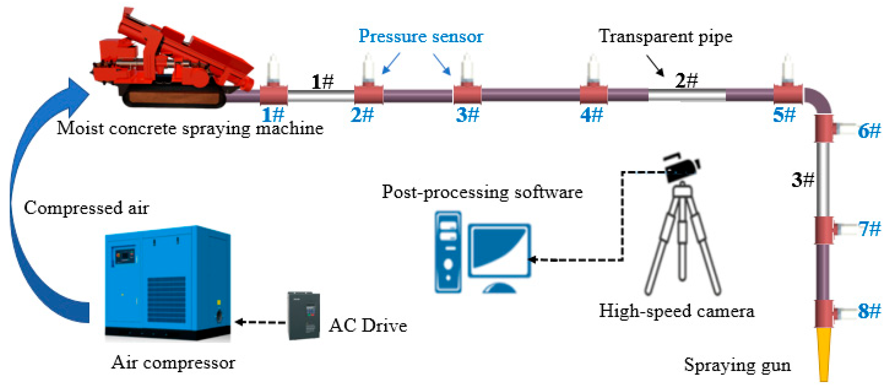
2.2. Experimental System

Figure 2 shows the schematic diagram of the experimental system used to test the flow characteristics of the pneumatic conveying of stiff shotcrete materials. The test pipe is one commonly used at the shotcrete work site, with an inner diameter of 63 mm. The layout is shown in Figure 2. All of them are horizontally arranged straight pipes (18 m long, to make the stiff shotcrete materials reach a stable conveying state before bending) that are connected with elbows with a certain bending-diameter ratio and finally connected to a section of horizontally arranged straight pipes until the materials are sprayed from the nozzle. Eight pressure transmitters (measuring range: 0~0.6 MPa) and three transparent acrylic tubes are placed in the pipeline. The pressure transmitter is mainly used to measure the pressure data in the pipeline, and the dynamic signal test and analysis system DAQM-4206C record all test data. The three transparent pipes are respectively arranged in the initial stage of pneumatic conveying (1 #), the stable stage of pneumatic conveying (2 #), and the stage after bending (3 #) to observe the material flow characteristics at different locations. This paper will focus on observing the flow characteristics of stiff shotcrete materials at the stage after elbow (3 #). A phantom v611 high-speed camera, produced by Vision Company of the United States, is used, with an average shooting rate of 550 FPS and the highest resolution of 1280 × 800. The gas power source provides compressed air. The air compressor with a rated power of 5.5 KW and a maximum transmission air velocity of 40 m/s is selected as the gas power source to transport air. In addition, to obtain stable pressure drop data, the conveying time of each pneumatic conveying experiment is kept at about 30 s. Due to the uncertainty of vortex flow meters and air compressors, it is difficult to accurately measure the air velocity; however, the impact on the experimental results can be ignored. The detailed introduction of material parameters and other operating conditions used in the experiment is shown in Table 1.

2.3. Experimental Scheme

The pressure fluctuation in the pneumatic conveying pipeline varies with the inlet gas velocity. The pressure fluctuation rate will lead to an unstable flow field and relatively high energy consumption. When measuring the dispersion of different data, it is not accurate to directly use standard deviation to compare the two groups. Using the coefficient of variation to compare them can eliminate the impact of measurement scale and size. C.V has no dimension, so we can objectively compare the pneumatic conveying of stiff shotcrete.
C . V = σ X E X
where C.V is the coefficient of variation, σ X is the standard deviation of the original data, and E X is the average of the original data.
The elbow pressure drop is defined as the pressure loss at the outlet compared with the pressure loss at the inlet, which reflects the elbow pressure drop:
p = p i n p o u t
where p is the pressure drop at the inlet and outlet of the elbow, p i n and p o u t is the pressure at the inlet and outlet of the elbow, respectively.
Thoroughly consider the influence of air velocity (A), water-cement ratio (B), and bending-diameter ratio (C) on the pressure drop at the inlet and outlet of the elbow and the conveying stability, and take the pressure drop at the inlet and outlet of the elbow (R1) and the conveying stability (R2) as the response values to conduct the experimental design of the three factors and three levels. The pressure variation coefficient characterizes conveying stability. A total of 17 schemes were designed using the Box-Benhnken practical design method, as shown in Table 2.

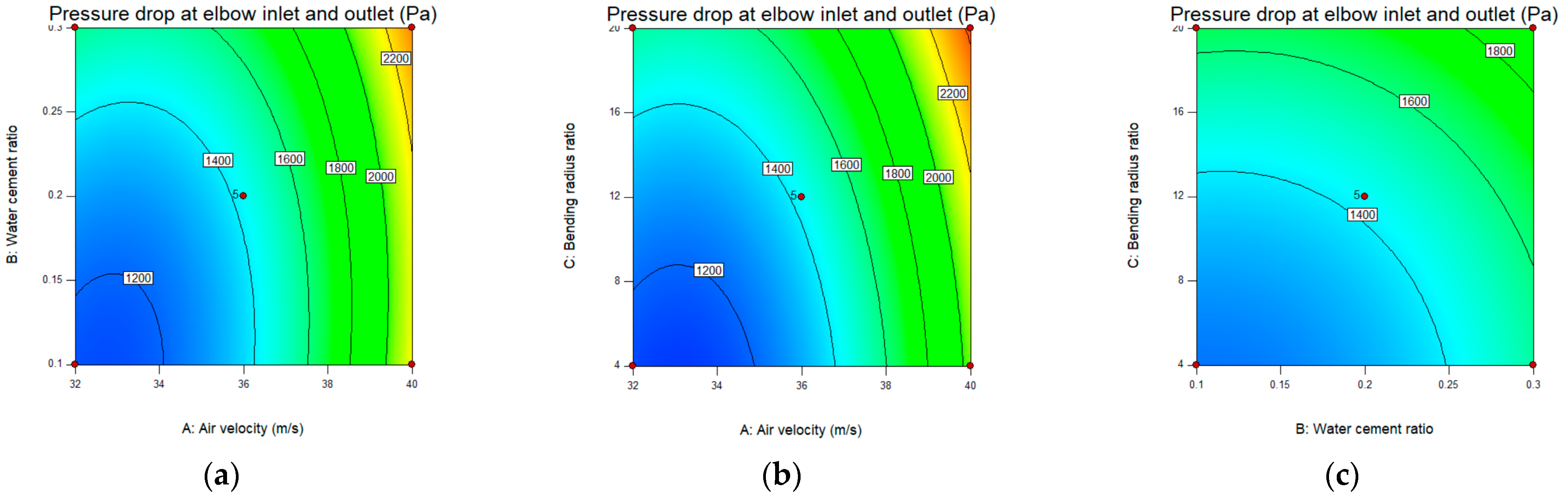
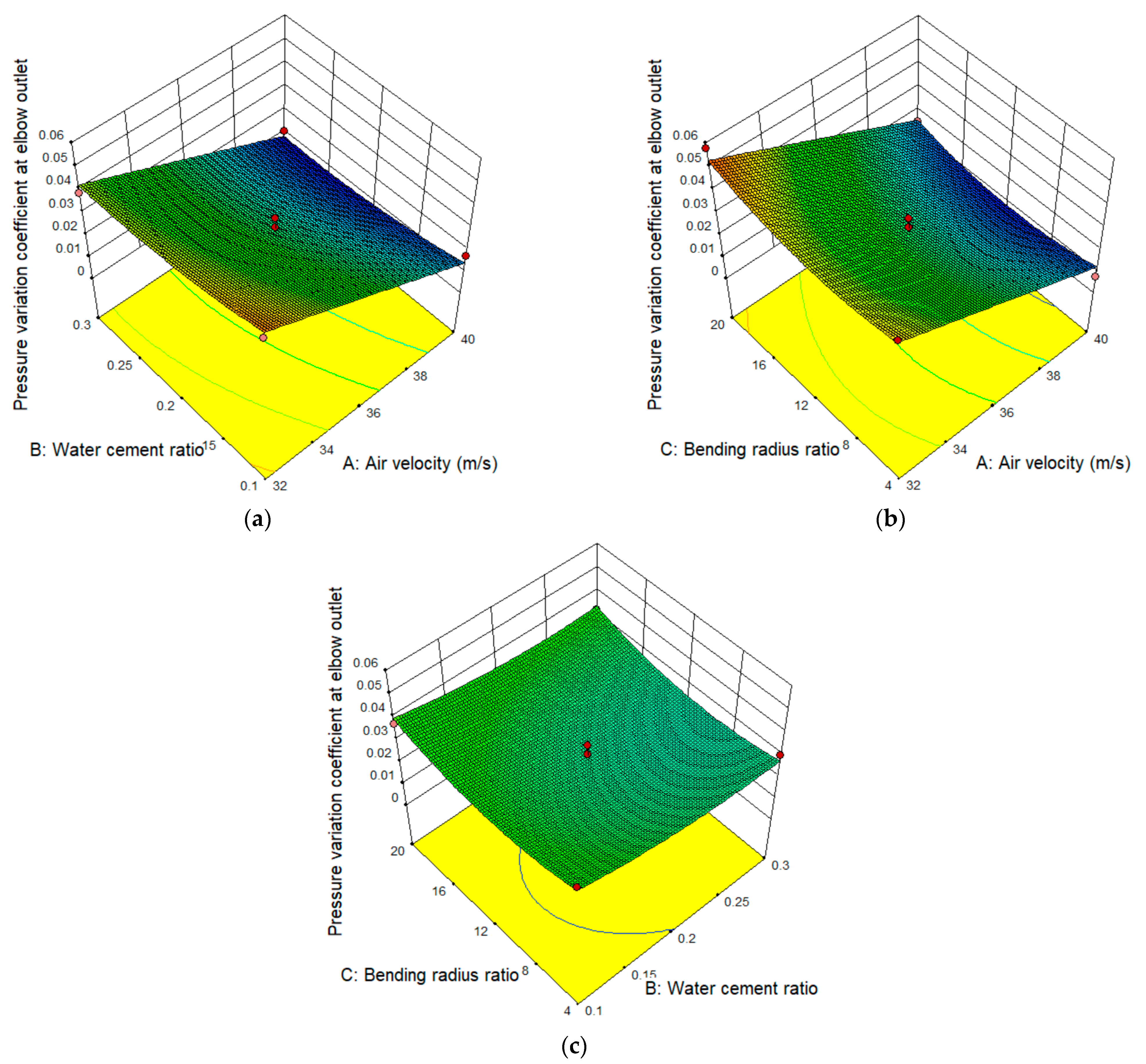
3. Calculation Results and Analysis

The regression simulation analysis of the test results in Table 2 was carried out using the Design Expert 10.0 software, and the second-order regression model between the elbow pressure drop and the air velocity, water-cement ratio, and bending-diameter ratio was obtained, as shown in Equation (3):
R 1 = 1430 + 439.62 A + 147.12 B + 196.75 C 56.25 A B 3.99 A C 17.99 B C + 300.12 A 2 + 85.12 B 2 + 67.37 C 2
Table 3 shows the results of the variance analysis of elbow pressure drop.
For the model ANOVA results, column P reflects the significance of the test factor in the model. When p < 0.05, the factor is significant. Otherwise, it is not substantial. The lack of fit reflects the degree of difference between the model and the test. When the item p > 0.05, it indicates that the model is significantly correlated with the test data. It can be seen from Table 3 that the model item p = 0.0003 < 0.001, shows that the effect of the model is significant. The lack of fit in this model p = 0.1396 > 0.05, indicates that the prediction value of this model is significantly correlated with the test value, and the fitting is good.
The regression simulation analysis of the test results in Table 2 was carried out using the Design Expert 10.0 software, and the second-order regression model between the conveying stability (C.V)e and air velocity, the water-cement ratio, and the bending-diameter ratio was obtained, as shown in Equation (4):
R 2 = 0.02662 0.0179 A 3.90 × 10 3 B + 2.17 × 10 3 C + 6.99 × 10 4 A B 6.50 × 10 4 A C + 9.50 × 10 4 B C 1.35 × 10 4 A 2 + 2.66 × 10 4 B 2 + 5.51 × 10 3 C 2
Table 4 shows the variance analysis results of the conveying stability (C.V) at the elbow outlet.
It can be seen from Table 4 that the model p = 0.0007 < 0.001, indicating that the effect of the model is significant. The lack of fit in this model p = 0.1318 > 0.05, indicates that the predicted value of this model is highly correlated with the experimental value, and the fitting is good.
By analyzing the model data, the 3D response surface and contour plot between air velocity, water-cement ratio, bending-diameter ratio, and R1, R2 are obtained, as shown in Figure 3, Figure 4, Figure 5 and Figure 6. The graph is composed of a response surface graph and a contour graph, where the density of the contour lines in the contour graph indicates the significance of each response factor on the response value. The curvature of the response surface and contour line shows the significant degree of interaction between response factors.
It can be seen from Figure 3 and Figure 4a that the contour line distribution of the abscissa is denser than that of the ordinate, which indicates that the air velocity has a more significant effect on the elbow pressure drop than the water-cement ratio. The response surface is distorted, meaning the interaction between the two is substantial. It can be seen from the trend of the three-dimensional curved surface that when the water-cement ratio is a particular value, the pressure drop at the inlet and outlet of the elbow increases with the increase in air velocity.
According to Figure 3 and Figure 4b, the contour lines in the abscissa are more densely distributed than those in the ordinate, indicating that the influence of air velocity on the elbow pressure drop is significantly greater than the bending-diameter ratio. The response surface is distorted, meaning the interaction between the two is significant. It can be seen from the trend of the three-dimensional curved surface that when the air velocity is a particular value, the elbow pressure drop increases with the increase in the bending-diameter ratio.
As is shown in Figure 3 and Figure 4c that the contour line distribution in the ordinate is more intensive than that in the abscissa, indicating that the influence of the bending-diameter ratio on the elbow pressure drop is more significant than that of the water-cement ratio. However, there is no noticeable distortion in the response surface, indicating that the interaction between the two is insignificant.
To summarize, the degree of influence for each factor on the elbow pressure drop is air velocity > bending-diameter ratio > water-cement ratio. In addition, there is a significant interaction between the air velocity and bending-diameter ratio, air velocity, and water-cement ratio. At the same time, there is no significant interaction between the bending-diameter ratio and the water-cement ratio.
It can be seen from Figure 5 and Figure 6a that the contour line distribution of the abscissa is significantly denser than that of the ordinate, which indicates that the influence of air velocity on the coefficient of variation of elbow outlet pressure is more significant than that of the water-cement ratio. However, there is no noticeable distortion in the response surface, indicating that the interaction between the two factors is insignificant. It can be seen from the trend of the three-dimensional curved surface that when the water-cement ratio is a particular value, the conveying stability (C.V) at the elbow outlet decreases with the increase in air velocity.
It is manifest from Figure 5 and Figure 6b that the contour lines in the abscissa are more densely distributed than those in the ordinate, indicating that the influence of air velocity on the conveying stability (C.V) at the elbow outlet is more significant than that of the bending-diameter ratio. However, there is no noticeable distortion in the response surface, indicating that the interaction between the two is insignificant. It can be seen from the trend of the three-dimensional curved surface that when the bending-diameter ratio is a particular value, the conveying stability (C.V) at the elbow outlet decreases with the increase in air velocity.
As is shown in Figure 5 and Figure 6c, the contour lines in the abscissa are more densely distributed than those in the ordinate, indicating that the water-cement ratio has a more significant influence on the conveying stability (C.V) of the elbow outlet than the bending-diameter ratio. The response surface is distorted, indicating that the interaction of the two is significant.
To sum up, the influence degree of each influencing factor on the pressure drop at the inlet and outlet of the elbow is air velocity > water-cement ratio > bending-diameter ratio. In addition, it is found that there is no significant interaction between air velocity and bending-diameter ratio, air velocity, and water-cement ratio. Still, there is considerable interaction between the bending-diameter ratio and the water-cement ratio.

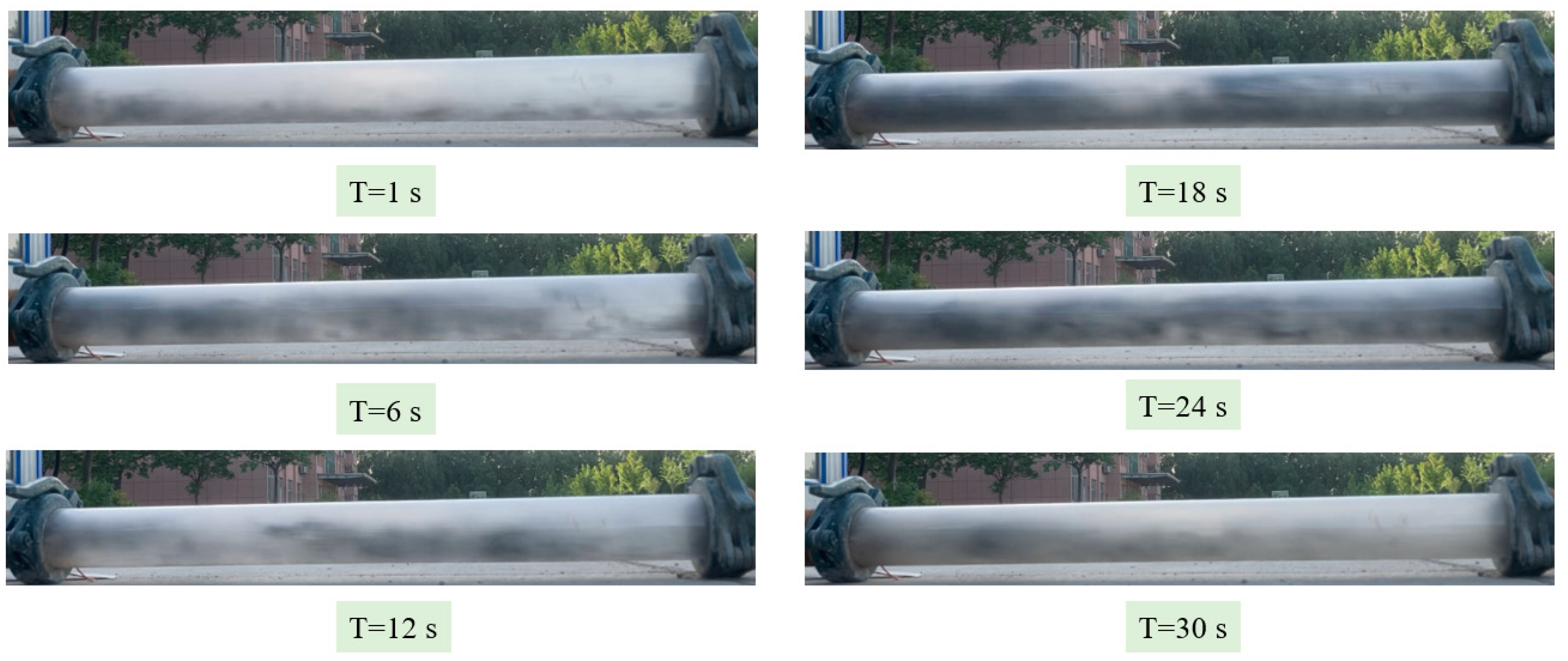
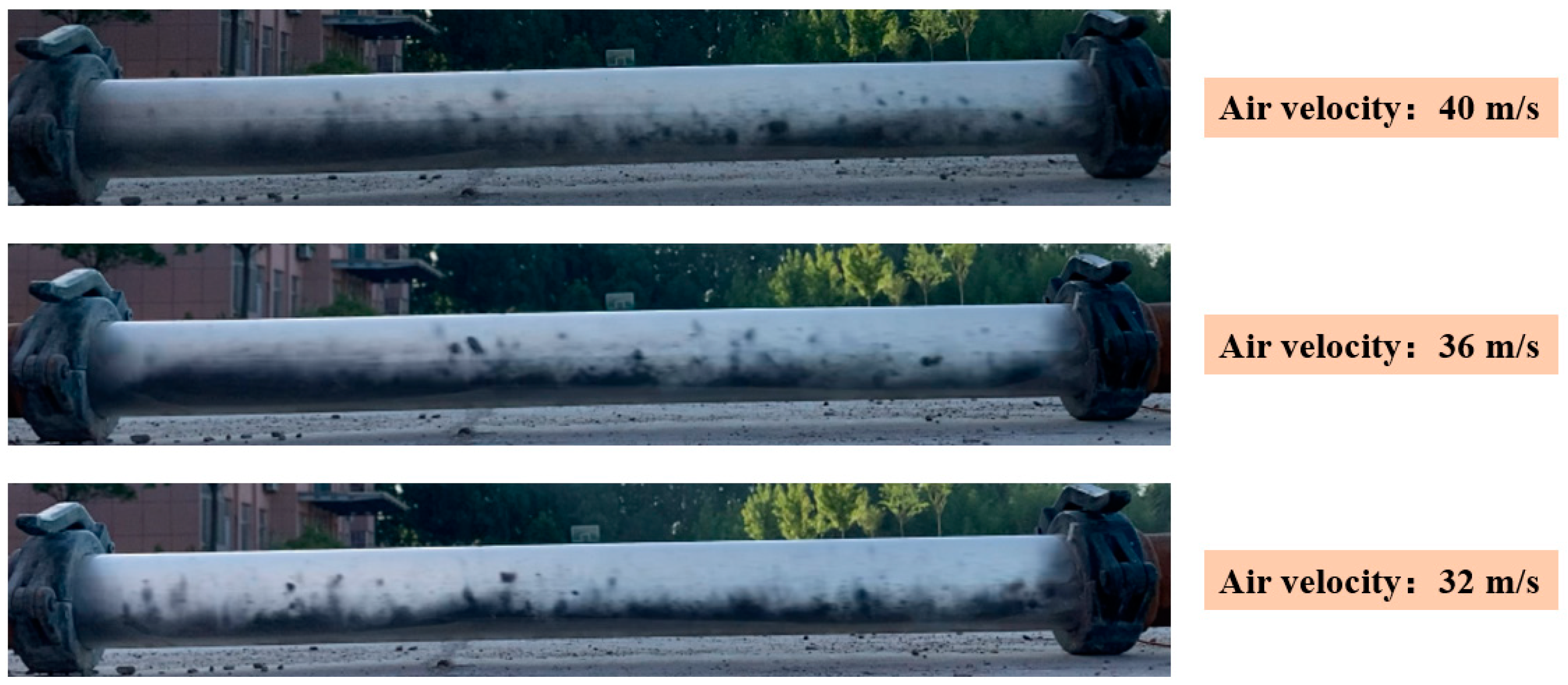
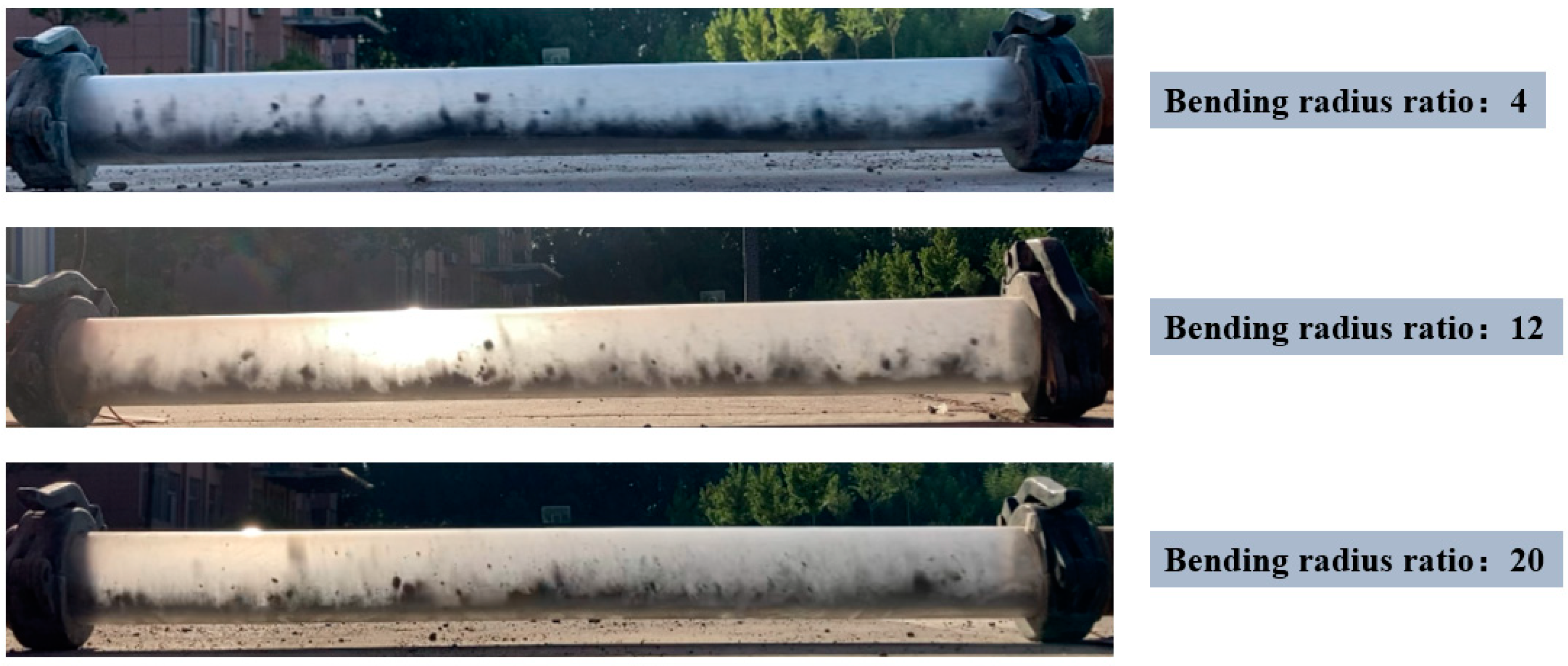
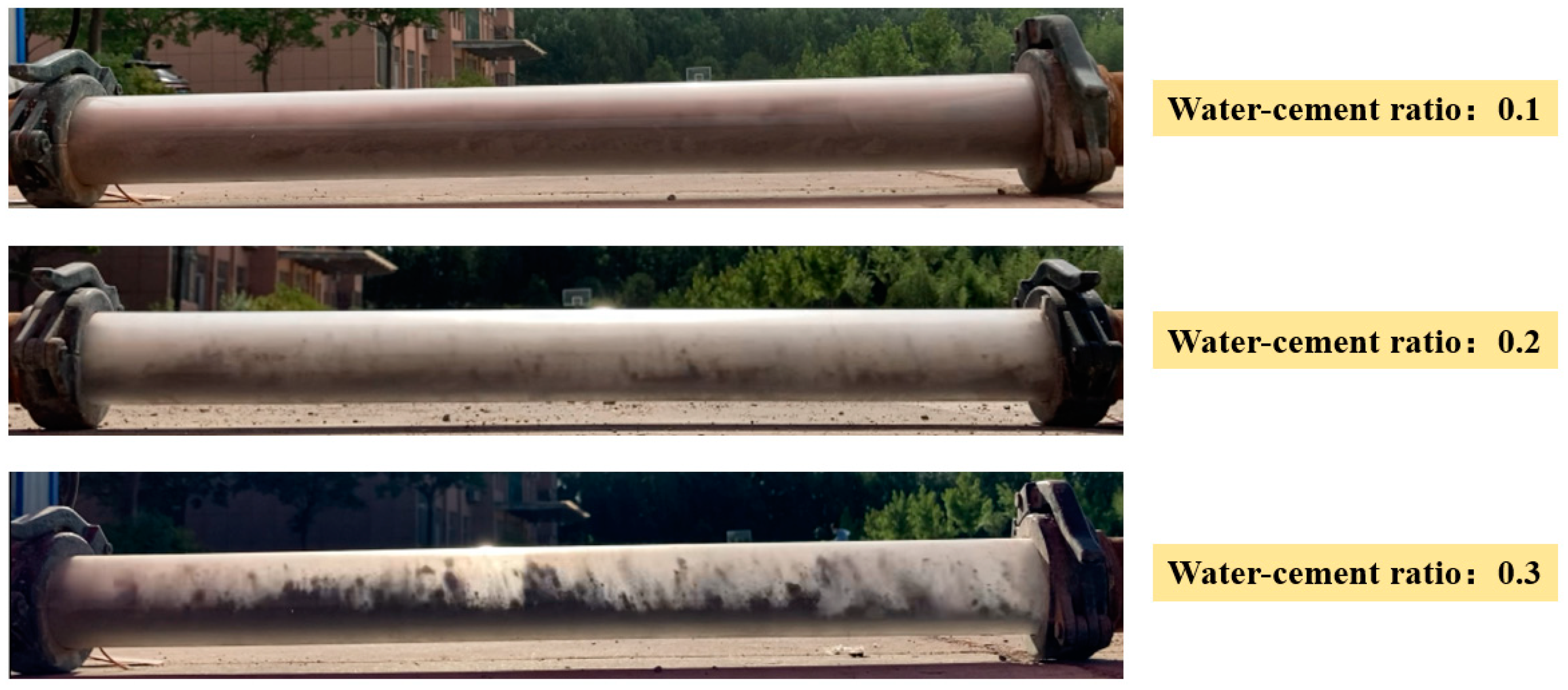
4. Flow Characteristics of Stiff Shotcrete in the Stage after Elbow

The flow characteristics of the material particles are studied by a high-speed camera. Figure 7 shows the snapshots of pneumatic conveying at different conveying positions under an air velocity of 40 m/s, a water-cement ratio of 0.2, and a bending-diameter ratio of 4. As shown in Figure 6, material particles belong to the acceleration section at the initial stage of transportation (Position 1 #). Under the action of air, the speed of the material particles of wet shotcrete increases rapidly, but they mainly move forward in the form of a bottom layer flow. Some coarse aggregate particles roll and suspend under the combined action of the airflow, pipe wall, and other material particles, while the particles at the lower part of the pipe slide irregularly. In the sound conveying stage (Position 2 #), the speed of the material particle group is maintained at a stable state after passing through the acceleration section and the particle group is picked up to reach the suspension state. However, in the stage (Position 3 #), after passing the elbow with a bending-diameter ratio of 4, the particle group of materials will collide violently with the elbow, and the particle group speed of materials will drop sharply. Under the combined action of the subsequent airflow and secondary flow, the particles in the upper part will be picked up layer by layer, gradually forming a suspended flow.
Figure 8 shows the snapshots of pneumatic conveying at different times when the air velocity is 40 m/s, the water-cement ratio is 0.2, and the bending-diameter ratio is 4. As shown in Figure 8, when stiff shotcrete particles pass through the outlet of the elbow, a small amount of sprayed concrete particles pass through the bottom of the pipe. Subsequently, due to the influence of air velocity and secondary flow, the stiff shotcrete particles form a stable suspended flow, which continues until the material particles are transported.
In Figure 9, a snapshot of the pneumatic transport of stiff shotcrete after bending is obtained under the conditions of a water-cement ratio of 0.3, a bending-diameter ratio of 4, and an air velocity of 40 m/s, 36 m/s, and 32 m/s, respectively. As shown in Figure 9, under different air velocities, the stiff shotcrete particles of wet shotcrete can reach a stable conveying process after passing through the bending stage. In addition, when the air velocity decreases, the flow pattern of the material particles of the stiff shotcrete gradually transits from suspension to bottom flow.
Figure 10 shows a snapshot of pneumatic conveying of stiff shotcrete particles material through elbow structures with different bending-diameter ratios when the air velocity is 32 m/s and the water-cement ratio is 0.3. It can be seen from Figure 10 that the particle groups are transported in a stable bottom flow. In addition, different bending-diameter ratios have no significant impact on the flow characteristics of particles.
Figure 11 shows the snapshot of the pneumatic conveying of stiff shotcrete material particles at different water-cement ratios under the conditions of 36 m/s air velocity and a bending-diameter ratio of 4. As shown in Figure 11, the material particle group keeps the bottom flow stable at this air velocity. It should be noted that when the water-cement ratio of the stiff shotcrete material is 0.1, a small amount of cement does not undergo a hydration reaction and is still transported pneumatically in powder form. As a result, cement accumulations of varying degrees occur at the bottom of the pipeline and slip forward at a shallow velocity relative to the suspended materials.

5. Conclusions

Field pressure conveying experiments studied the pressure drop and conveying stability of the elbow under different air velocities, water-cement ratios, and bending-diameter ratios. The investigation is designed based on the response surface method, and the experimental data are analyzed. Among them, the conveying stability is characterized by the pressure variation coefficient. The influence of the interaction of single and multiple factors on the pressure drop and conveying stability of the elbow is analyzed. However, these conclusions are limited to the range of parameters studied. The main conclusions are as follows:
(1) The influence degree of a single factor on the elbow pressure drop is as follows: air velocity > bending-diameter ratio > water-cement ratio and the degree of influence of a single factor on conveying stability is as follows: air velocity > water-cement ratio > bending-diameter ratio. Therefore, the effect of air velocity on the pressure drop and conveying stability of the elbow is significant.
(2) The response surface model of air velocity, water-cement ratio, bending-diameter ratio, and elbow pressure drop R1 is established. The second-order response surface model of air velocity, water-cement ratio, bending-diameter ratio, and the conveying stability (C.V) of elbow outlet R2 is found. In addition, there is a significant interaction between air velocity and bending-diameter ratio, air velocity, and water-cement ratio for the pressure drop at the inlet and outlet of the elbow. For conveying stability (C.V), there is still a considerable interaction between the bending-diameter and water-cement ratios.
(3) By comparing the snapshot analysis of the section after passing through the bend under different working conditions, it can be seen that the air velocity significantly impacts the flow characteristics after passing through the elbow. The air velocity substantially influences the flow characteristics of the material particles after passing through the elbow. With the air velocity increase, the particle group gradually transits from the bottom layer to the suspended flow. The water-cement and bending-diameter ratios have no significant effect on the flow characteristics of the material particles after passing through the elbow.

Author Contributions

Writing—original draft preparation, Z.S.; writing—review and editing, Z.S.; methodology, Z.S.; software, Z.S.; validation, Z.S.; supervision, L.C., H.M. and K.G.; formal analysis, L.C; investigation, G.M.; data curation, G.M.; project administration, G.M. All authors have read and agreed to the published version of the manuscript.

Funding

This study was funded by projects such as National Natural Science Foundation of China (Grant No. 51974177, 51934004, 52104199, 52104206); Natural Science Foundation of Shandong (Grant No. ZR2019QEE007, ZR2019MEE115, ZR2022QE177); China National Scholarship Fund (202208370124); Special funds for Taishan scholar project; Major scientific and technological innovation projects of Shandong Province (Grant No. 2019SDZY0203).

Institutional Review Board Statement

Not applicable.

Informed Consent Statement

Not applicable.

Data Availability Statement

All data supporting the conclusions of this study are included within the manuscript.

Conflicts of Interest

The authors declare no conflict of interest.

References

  1. Liu, G.; Cheng, W.; Chen, L.; Gang, P.; Liu, Z. Rheological properties of fresh concrete and its application on shotcrete. Constr. Build. Mater. 2020, 243, 118180. [Google Scholar] [CrossRef]
  2. Chen, L.; Ma, G.; Liu, G.; Liu, Z. Effect of pumping and spraying processes on the rheological properties and air content of wet-mix shotcrete with various admixtures. Constr. Build. Mater. 2019, 225, 311–323. [Google Scholar] [CrossRef]
  3. Galan, I.; Baldermann, A.; Kusterle, W.; Dietzel, M.; Mittermayr, F. Durability of shotcrete for underground support—Review and update. Constr. Build. Mater. 2019, 202, 465–493. [Google Scholar] [CrossRef]
  4. Ginouse, N.; Jolin, M.; Bissonnette, B. Effect of equipment on spray velocity distribution in shotcrete applications. Constr. Build. Mater. 2014, 70, 362–369. [Google Scholar] [CrossRef]
  5. Guoqing, S.; Jianguo, N.; Minghao, D.; Ruyu, Y.; Zhi, Z. Multi-factor analysis of roof subsidence of paste filling face based on response surface method. J. Shandong Univ. Sci. Technol. (Nat. Sci.) 2022, 41, 9. [Google Scholar]
  6. Zhongchang, W.; Yang, C.; Jian, S.; Hongchun, X. Analysis of erosion wear of filling slurry on reducing pipes. J. Shandong Univ. Sci. Technol. (Nat. Sci.) 2022, 4, 041. [Google Scholar]
  7. Yun, K.-K.; Panov, V.; Han, S.; Kim, S.U.; Kim, S. Rheological based interpretation of shotcrete pumpability and shootability. Constr. Build. Mater. 2022, 328, 127073. [Google Scholar] [CrossRef]
  8. Sun, Z.; Chen, L.; Yu, X.; Liu, G.; Ma, H. Study on optimization of shotcrete loading technology and the diffusion law of intermittent dust generation. J. Clean. Prod. 2021, 312, 127765. [Google Scholar] [CrossRef]
  9. Yin, L.; Yalan, G.; Hao, L.; Haoyu, W. Experimental study on effect of recycled aggregate from construction waste on conveying performance of mine filling paste. J. Shandong Univ. Sci. Technol. (Nat. Sci.) 2020, 39, 7. [Google Scholar]
  10. Chen, L.; Sun, Z.; Liu, G.; Ma, G.; Liu, X. Spraying characteristics of mining wet shotcrete. Constr. Build. Mater. 2022, 316, 125888. [Google Scholar] [CrossRef]
  11. Armengaud, J.; Casaux-Ginestet, G.; Cyr, M.; Husson, B.; Jolin, M. Characterization of fresh dry-mix shotcrete and correlation to rebound. Constr. Build. Mater. 2017, 135, 225–232. [Google Scholar] [CrossRef]
  12. Ginouse, N.; Jolin, M. Investigation of spray pattern in shotcrete applications. Constr. Build. Mater. 2015, 93, 966–972. [Google Scholar] [CrossRef]
  13. Kalman, H.; Santo, N.; Tripathi, N.M. Particle velocity reduction in horizontal-horizontal bends of dilute phase pneumatic conveying. Powder Technol. 2019, 356, 808–817. [Google Scholar] [CrossRef]
  14. Portnikov, D.; Santo, N.; Kalman, H. Simplified model for particle collision related to attrition in pneumatic conveying. Adv. Powder Technol. 2020, 31, 359–369. [Google Scholar] [CrossRef]
  15. Santo, N.; Kalman, H. Blinded T-bends flow patterns in pneumatic conveying systems. Powder Technol. 2017, 321, 347–354. [Google Scholar] [CrossRef]
  16. Tripathi, N.M.; Portnikov, D.; Levy, A.; Kalman, H. Bend pressure drop in horizontal and vertical dilute phase pneumatic conveying systems. Chem. Eng. Sci. 2019, 209, 115228. [Google Scholar] [CrossRef]
  17. Tripathi, N.M.; Santo, N.; Levy, A.; Kalman, H. Experimental analysis of velocity reduction in bends related to vertical pipes in dilute phase pneumatic conveying. Powder Technol. 2019, 345, 190–202. [Google Scholar] [CrossRef]
  18. Nir, S.; Dmitry, P.; Mani, T.N.; Haim, K. Experimental study on the particle velocity development profile and acceleration length in horizontal dilute phase pneumatic conveying systems. Powder Technol. 2018, 339, 368–376. [Google Scholar]
  19. Tu, P.; Shao, Y.; Chen, Q.; Yan, F.; Liu, P. Multi-scale analysis on particle dynamic of vertical curved 90° bend in a horizontal-vertical pneumatic conveying system. Adv. Powder Technol. 2021, 32, 3136–3148. [Google Scholar] [CrossRef]
  20. Feng, Z.A.; Jl, A.; Dy, B.; Yl, A. Experimental study on collision characteristics of large coal particles (7–15mm) in 90° elbows of pneumatic conveying systems. Powder Technol. 2021, 396, 305–315. [Google Scholar]
  21. Ji, Y.; Liu, S.; Li, J. Experimental and numerical studies on dense-phase pneumatic conveying of spraying material in venturi. Powder Technol. 2018, 339, 419–433. [Google Scholar] [CrossRef]
  22. Ji, Y.; Liu, S.; Li, J. Experimental study of supply pressure on spraying materials in horizontal pipe. Vacuum 2019, 159, 51–58. [Google Scholar] [CrossRef]
  23. Nambiar, E.K.K.; Ramamurthy, K. Models relating mixture composition to the density and strength of foam concrete using response surface methodology. Cem. Concr. Compos. 2006, 28, 752–760. [Google Scholar] [CrossRef]
  24. Hamada, H.M.; Al-Attar, A.; Shi, J.; Yahaya, F.; Al Jawahery, M.S.; Yousif, S.T. Optimization of sustainable concrete characteristics incorporating palm oil clinker and nano-palm oil fuel ash using response surface methodology. Powder Technol. 2023, 413, 118054. [Google Scholar] [CrossRef]
  25. Miao, Z.; Kuang, S.; Zughbi, H.; Yu, A. CFD simulation of dilute-phase pneumatic conveying of powders. Powder Technol. 2019, 349, 70–83. [Google Scholar] [CrossRef]
  26. Kuang, S.; Zhou, M.; Yu, A. CFD-DEM modelling and simulation of pneumatic conveying: A review. Powder Technol. 2020, 365, 186–207. [Google Scholar] [CrossRef]
  27. Miao, Z.; Kuang, S.; Zughbi, H.; Yu, A. Numerical simulation of dense-phase pneumatic transport of powder in horizontal pipes. Powder Technol. 2020, 361, 62–73. [Google Scholar] [CrossRef]
  28. Hz, A.; Hx, A.; Wz, B.; Ay, C. Experimental study on conveying characteristics of a novel top-discharge blow tank for fine cohesive powders. Powder Technol. 2020, 379, 335–344. [Google Scholar]
  29. Zhou, M.; Kuang, S.; Xiao, F.; Luo, K.; Yu, A. CFD-DEM analysis of hydraulic conveying bends: Interaction between pipe orientation and flow regime. Powder Technol. 2021, 392, 619–631. [Google Scholar] [CrossRef]
  30. Zhao, X.; Cao, X.; Xie, Z.; Cao, H.; Wu, C.; Bian, J. Numerical study on the particle erosion of elbows mounted in series in the gas-solid flow. J. Nat. Gas Sci. Eng. 2022, 99, 104423. [Google Scholar] [CrossRef]
  31. Zhou, H.; Zhang, Y.; Bai, Y.; Zhao, H.; Lei, Y.; Zhu, K.; Ding, X. Study on reducing elbow erosion with swirling flow. Colloids Surf. A Physicochem. Eng. Asp. 2021, 630, 127537. [Google Scholar] [CrossRef]
  32. Xu, L.; Zhang, Q.; Zheng, J.; Zhao, Y. Numerical prediction of erosion in elbow based on CFD-DEM simulation. Powder Technol. 2016, 302, 236–246. [Google Scholar] [CrossRef]
  33. Solnordal, C.B.; Wong, C.Y.; Boulanger, J. An experimental and numerical analysis of erosion caused by sand pneumatically conveyed through a standard pipe elbow. Wear 2015, 336, 43–57. [Google Scholar] [CrossRef]
  34. Mechtcherine, V.; Gram, A.; Krenzer, K.; Jörg-Henry, S.; Shyshko, S.; Roussel, N. Simulation of fresh concrete flow using Discrete Element Method (DEM): Theory and applications. Mater. Struct. 2013, 47, 615–630. [Google Scholar] [CrossRef]
  35. Ma, G.; Sun, Z.; Ma, H.; Li, P. Calibration of Contact Parameters for Moist Bulk of Shotcrete Based on EDEM. Adv. Mater. Sci. Eng. 2022, 2022, 6072303. [Google Scholar] [CrossRef]
  36. Chen, L.; Sun, Z.; Ma, H.; Pan, G.; Li, P.; Gao, K. Flow characteristics of pneumatic conveying of stiff shotcrete based on CFD-DEM method. Powder Technol. 2022, 397, 117109. [Google Scholar] [CrossRef]
  37. Ma, G.; Ma, H.; Sun, Z. Simulation of Two-Phase Flow of Shotcrete in a Bent Pipe Based on a CFD-DEM Coupling Model. Appl. Sci. 2022, 12, 3530. [Google Scholar] [CrossRef]
  38. Chen, L.; Sun, Z.; Li, P.; Ma, H.; Pan, G. DEM simulation of the transport of mine concrete by a screw feeder. J. Braz. Soc. Mech. Sci. Eng. 2022, 44, 280. [Google Scholar] [CrossRef]
  39. Chen, L.; Sun, Z.; Ma, H.; Li, P.; Ma, G.; Gao, K.; Zhang, Y. Energy loss caused by the elbow of stiff shotcrete pneumatic conveying based on response surface method and CFD-DEM. Powder Technol. 2022, 408, 117726. [Google Scholar] [CrossRef]
  40. Chen, L.; Ma, H.; Gao, K.; Sun, Z. Experimental study on the flow characteristics of horizontal pneumatic conveying of stiff shotcrete. J. Build. Eng. 2023, 73, 106765. [Google Scholar] [CrossRef]
  41. GB 50086-2015; China MoHaU-RDotPsRo. Technical Code for Engineering of Ground Anchorages and Shotcrete Support. China Metallurgical Building Research Institute Co., Ltd.: Beijing, China, 2015.
Figure 1. The production process of stiff shotcrete materials.
Processes 11 01574 g001
Figure 2. A schematic diagram of the experimental system.
Processes 11 01574 g002
Figure 3. The 3D response surface of the pressure drop at the elbow inlet and outlet. (a) The impact of factors A and B on R1, (b) The impact of factors A and C on R1, (c) The impact of factors B and C on R1.
Processes 11 01574 g003
Figure 4. The contour plot of pressure drop at the elbow inlet and outlet.(a) The impact of factors A and B on R1, (b) The impact of factors A and C on R1, (c) The impact of factors B and C on R1.
Processes 11 01574 g004
Figure 5. The 3D response surface of conveying stability (C.V) of the elbow outlet. (a) The impact of factors A and B on R2, (b) The impact of factors A and C on R2, (c) The impact of factors B and C on R2.
Processes 11 01574 g005
Figure 6. The contour plot of the conveying stability (C.V) of the elbow outlet. (a) The impact of factors A and B on R2, (b) The impact of factors A and C on R2, (c) The impact of factors B and C on R2.
Processes 11 01574 g006
Figure 7. The flow characteristics of stiff shotcrete particles at three different positions.
Processes 11 01574 g007
Figure 8. The flow characteristics of stiff shotcrete particles at different times.
Processes 11 01574 g008
Figure 9. The flow characteristics of stiff shotcrete particles at different air velocities.
Processes 11 01574 g009
Figure 10. The flow characteristics of stiff shotcrete particles under different bending-diameter ratios.
Processes 11 01574 g010
Figure 11. The flow characteristics of stiff shotcrete particles under different water-cement ratios.
Processes 11 01574 g011
Table 1. Material Parameters and Operating Conditions.
PropertiesValuePropertiesValue
Water-cement ratio0.1, 0.2, 0.3Apparent density of coarse aggregate (kg/m3)2500
Apparent density of fine aggregate (kg/m3)2400Bulk density of coarse aggregate (kg/m3)1420
Bulk density of fine aggregate (kg/m3)1510Air velocity (m/s)32, 36, 40
Table 2. The Test Design and Results.
TestAir VelocityWater-Cement RatioBending-Diameter RatioPressure Drop at the ElbowConveying Stability (C.V)
1320.11212000.0492
2320.31215870.0392
3400.11221560.0177
4400.31223180.0105
5360.1413000.0291
6360.3416500.0332
7360.12015510.0335
8360.32018290.0370
9320.2410500.0479
10400.2419730.0077
11320.22015300.0576
12400.22025370.0188
13360.21214640.0272
14360.21213810.0251
15360.21215020.0313
16360.21215100.0266
17360.21214930.0329
Table 3. The variance analysis of the elbow inlet and outlet pressure drop model.
SourceSum of
Squares
dfMean
Square
F
Value
p-Value
Prob > F
Model2.499 × 10692.776 × 10520.640.0003significant
A-Air velocity1.546 × 10611.546 × 106114.93<0.0001
B-Water-cement ratio1.732 × 10511.732 × 10512.870.0089
C-bending-diameter ratio3.097 × 10513.097 × 10523.020.0020
AB12,656.25112,656.250.940.3644
AC64.00164.004.757 × 10−30.9469
BC1296.0011296.000.0960.7653
A23.793 × 10513.793 × 10528.190.0011
B230,510.59130,510.592.270.1758
C219,113.22119,113.221.420.2721
Residual94,170.75713,452.96
Lack of Fit67,060.75322,353.583.300.1396not significant
Pure Error27,110.0046777.50
Cor Total2.593 × 10616
R2 = 0.9637; R2adj = 0.9170; CV = 7.06%; Adequate precision = 14.307.
Table 4. The variance analysis of the elbow outlet conveying stability (C.V)model.
SourceSum of
Squares
dfMean
Square
F
Value
p-Value
Prob > F
Model2.895 × 10−393.217 × 10−416.380.0007significant
A-Air velocity2.563 × 10−312.563 × 10−3130.54<0.0001
B-Water-cement ratio1.217 × 10−411.217 × 10−46.200.0416
C- bending-diameter ratio3.784 × 10−513.784 × 10−51.930.2076
AB1.960 × 10−611.960 × 10−60.1000.7613
AC1.690 × 10−611.690 × 10−60.0860.7777
BC3.610 × 10−613.610 × 10−60.180.6810
A27.674 × 10−817.674 × 10−83.908 × 10−30.9519
B22.990 × 10−512.990 × 10−51.520.2570
C21.281 × 10−411.281 × 10−46.520.0379
Residual1.375 × 10−471.964 × 10⁻⁵
Lack of Fit9.907 × 10−533.302 × 10−53.440.1318not significant
Pure Error3.839 × 10−549.597 × 10⁻⁶
Cor Total3.033 × 10−316
R2 = 0.9547; R2adj = 0.8964; CV = 14.57%; Adequate precision = 13.134.
Disclaimer/Publisher’s Note: The statements, opinions and data contained in all publications are solely those of the individual author(s) and contributor(s) and not of MDPI and/or the editor(s). MDPI and/or the editor(s) disclaim responsibility for any injury to people or property resulting from any ideas, methods, instructions or products referred to in the content.

