Article

Heat Transfer Characteristics of Oil-Based Drill Cuttings in Thermal Desorption Chambers

1
School of Engineering, China University of Petroleum-Beijing at Karamay, Karamay 102249, China
2
School of Chemical Engineering, Southwest Petroleum University, Shanghai 610500, China
*
Author to whom correspondence should be addressed.
Processes 2023, 11(5), 1374; https://doi.org/10.3390/pr11051374
Submission received: 1 March 2023 / Revised: 1 April 2023 / Accepted: 25 April 2023 / Published: 2 May 2023

Abstract

:
Thermal desorption technologies have been extensively applied for the disposal of oil-based drill cuttings. Fluent-software-based phase changes in multiphase flow models within thermal desorption chamber temperature field simulations were examined to study the effects of oil-based drill cuttings fluid content and feed rates, nitrogen content, thermal desorption chamber length and diameter, and extraction tube position on the thermal desorption chamber and temperature field. Our results demonstrate that these factors had a considerable influence on the temperature field of the chamber, with the liquid content of the oil-based drill cuttings having the greatest influence. The heat transfer process was enhanced by appropriately increasing the diameter and length of the chamber and reasonably setting the extraction tube. When the chamber length was insufficient, there was a risk that the outlet temperature would be extremely low and the oil content of the residue would exceed the standard. The higher the feeding and nitrogen entering rates of the oil cuttings, the higher the liquid content of the oil cuttings and the lower the temperature in the chamber. Based on the heat transfer characteristics of the oil-based drill cuttings in the thermal desorption chamber, this study provides a theoretical basis for the design and application of oil-bearing cutting thermal desorption devices.

1. Introduction

Oil-based drill cuttings are generated by drilling with oil-based drilling fluid during oil and natural gas exploitation. These cuttings are dangerous owing to their toxic and carcinogenic components, such as polycyclic aromatic hydrocarbons (PAHs) [1], contained in the adhesive oil; therefore, there is an urgent need for the safe disposal of these cuttings. Thermal desorption is a harmless physical treatment method for heat-based solid–liquid separation, which has high efficiency and allows for oil resource recovery when used for oil-based drill cutting disposal [2,3,4,5,6]. This thermal desorption has been listed as an encouraged priority technology in the Environmental Management Guide for Hazardous Waste Onshore Oil and Gas Exploitation (Announcement No. 74, 2021) in China and has been applied in Xinjiang, Sichuan, and Chongqing in China [7,8].
Thermal desorption devices can be divided based on different classification methods [9]. Currently, oil-based drill cutting thermal desorption devices using spiral drive continuous feed and indirect heating are the most common, which provide anti-coking, stable operation, and uniform residue heating [10]. Thermal desorption chambers are the core of the heat transfer units within these thermal desorption devices, and the desorption separation of water, oil, and solid residues in oil-based drill cuttings is completed inside the chamber [11]. The device structure [12,13], such as the diameter and length of the thermal desorption chamber and the location of the extraction tube, has a direct influence on the thermal desorption heat transfer process of oil-based drill cuttings. Meanwhile, the liquid content of oil-based drill cuttings—that is, the sum of the water and oil contents and the feeding—and the nitrogen inflow speeds of oil-based drill cuttings also affect the heat transfer process.
Thermal desorption chambers and their supporting devices are expensive, so it is not suitable to manufacture these devices with different device structures for experimentation; therefore, simulations are the most suitable research method [14,15,16,17]. Zhao et al. [18] numerically simulated the forced convection heat transfer inside the spiral-driven heat exchanger and obtained the relationship among the heat transfer coefficients of cuttings in oil-based drilling. Gao et al. [19] simulated the continuous and simultaneous pyrolysis reaction of oily sludge in a rotary kiln and found that the pyrolysis temperature had a significant impact on the yields of CH4, CO, and H2, and a further study found that rotational speeds affect the temperature field of the chamber [20]. Nguyen et al. [21] determined that reasonable heat exchanger wall material selection can considerably reduce the influence of solid wall thermal conductivity on the heat transfer efficiency. Current industry research focuses on the interrelationships among operating parameters [22], such as heating temperature, heating time, oil content, recovered oil, and components of thermal desorption residue [23,24,25]. Currently, limited studies have been conducted on the interaction of oil-based drill cutting liquid contents and the structures and operating parameters of thermal desorption devices on thermal desorption chamber temperatures. This gap in our understanding leads to relatively high energy consumption during the thermal desorption of oil-based drill cuttings, which restricts the future development of this technology.
Therefore, in this paper, a simplified thermal desorption chamber model was used with the Fluent software to study the influence of six factors on the temperature field of the thermal desorption chamber, including the diameter, length, location of the extraction tube, and other device structures, on the indirect heating mode of spiral-driven continuous feed and to reveal the heat transfer characteristics of oil-based drill cuttings in the thermal desorption chamber. We propose specific structures and operational parameters for the thermal desorption chamber that enhance the heat transfer efficiency, which provides a reference for the development of a high-efficiency and energy-saving thermal desorption device.

2. Numerical Simulation Method

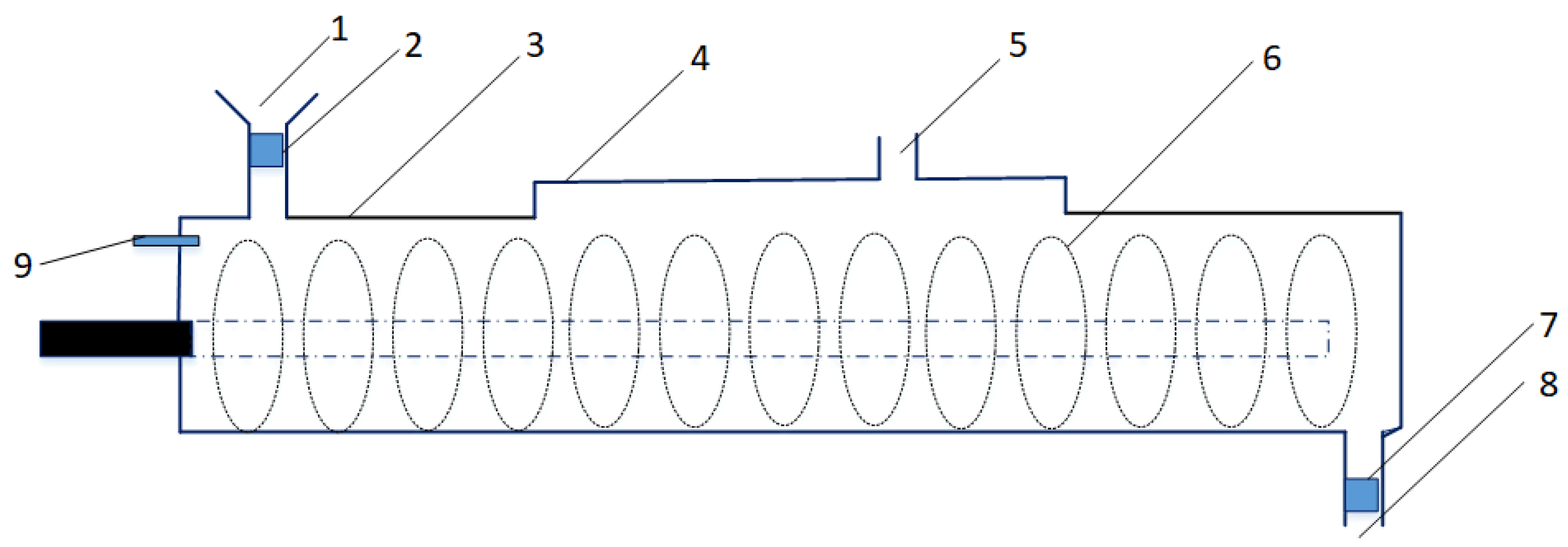
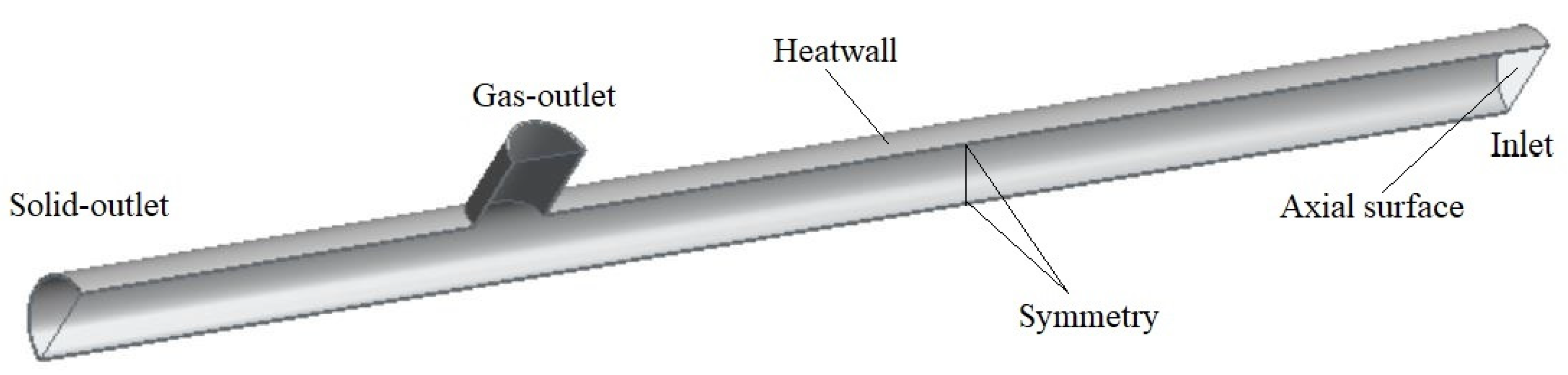
2.1. Geometric Model

The chambers of thermal desorption devices applied in engineering are shown in Figure 1, Main geometric parameters and variation range of a thermal desorption chamber in Table 1, including their feeding port, air inlet, discharge port, and extraction tube. After oil-based drill cuttings are heated in the thermal desorption chamber, water vapour is generated by the evaporation, and oil and other organic matter in the drilling fluid additives are desorbed to produce oil vapour, which is discharged from the extraction pipe together with inert protective gas. Solid residue is discharged from the discharge port by the screw propeller.
Inert gas and oil-based drill cuttings driven by propellers enter from the chamber inlet at a certain speed, and various gas mixtures and residues are output from the gas and solid outlets, respectively. The problem is simplified in the heat transfer and phase transformation problems of the multiphase flow in similar “T”-shaped tubes (Figure 2).

2.2. Simulation Conditions and the Control Equation

2.2.1. Model Assumes Oil-Based Drill Cuttings

The thermal desorption processes of the heat and mass transfer with phase transformation, such as cracking reactions and thermal desorption, are complex; therefore, to simulate in the research, this study made the following simplifications and assumptions:
(1)
When the propeller is at rest, oil-based drill cuttings achieve a certain speed from the inlet to the outlet.
(2)
The heat transfer rate of the thermal desorption chamber is infinite, and the wall surface of the chamber is constant and equal.
(3)
The diffusion velocity of thermal desorption gases, such as water and oil vapours, in oil-based drill cuttings is infinite; that is, water and oil components in oil-based drill cuttings reach the boiling point and migrate and diffuse rapidly from oil-based drill cuttings, ignoring the diffusion and secondary heat transfer processes within particles and between layers.
(4)
The chemical process and internal heat in the reaction process were ignored.

2.2.2. Continuity Equation

The motion of oil-based drill cuttings in the thermal desorption cavity was regarded as multiphase flow, and the continuity equation is:
ν x ρ x + ν y ρ y + ν z ρ z + ρ t = 0
where vx, vy, and vz are the velocity components of the x, y, and z direction velocities (m/s), ρ is the density of the fluid (g/cm3), and t is the time (s).

2.2.3. Momentum Conservation Equation

In inertial coordinates, the momentum conservation equation in direction I is:
t ρ ν i + x j ρ ν i ν j = p x i + τ i j c j + ρ g i
where P is the static pressure (Pa), τ i j . is the stress tensor, and ρ g i is the gravitational volume force (Pa). The oil-based drill cuttings are affected by the gravitational volume force along the direction below the thermal desorption chamber, which was set as −9.81 m/s2 in the x direction.

2.2.4. Energy Conservation Equation

The process of phase transition and heat transfer in the thermal desorption cavity should follow the Energy Conservation Equation:
ρ E t + · ν ρ E + p = · k e f f T j h j J j + τ e f f · ν
where E is the micro unit on the internal, potential, and kinetic energies (J/kg), and the sum of for the vector differential operator—that is, the total differential in the history of each position in space—is k e f f T ,   j h j J j ,   τ e f f · ν , followed by the heat transfer energy source term, multiple sets of divergence caused by the component diffusion energy source term, and viscous dissipation caused by the energy source term.

2.3. Physical and Chemical Properties and Feeding Speed of Oil-Based Drill Cuttings

The samples were obtained from the #0 diesel-based drilling fluid drilling site, which has oil, water, and solid contents of 9.65%, 6.94%, and 83.41%, respectively, and oil, water, and solid densities of 0.84, 1.0, and 2.18 g/cm3, respectively. The corresponding volume fractions were 20.66%, 12.18%, and 67.16%, respectively, and the oil content of the thermal desorption residue was set as 0.3%, that is, the maximum threshold of agricultural soil pollution control in China. Other main parameters required for the oil-based drill cuttings simulation in Table 2.
When the device was running, the oil-based drill cuttings were evenly distributed at the bottom of the thermal desorption chamber, with the feeding speeds defined as follows:
ν D O C = m O D C ρ O D C 4 π D 2
where ν O D C is the feeding velocity of the oil-based drill cuttings (m/s) at the entrance of the thermal desorption chamber, m O D C is the mass velocity of the oil-based drill cuttings (0.69 kg/s; 2.5 T/h), ρ O D C is the density of the oil-based drill cuttings (g/cm3), and D is the diameter of the thermal desorption chamber (m). The calculated entry velocity of the oil-based drill cuttings was approximately 0.0027–0.0036 m/s.

2.4. Nitrogen Feeding Speed

To prevent the risk of flash steam ignition and an explosion in the thermal desorption chamber, nitrogen was continuously injected into the chamber to form anaerobic or hypoxic conditions. The nitrogen production speed was 60 m3/h, and nitrogen was provided to the inlet and outlet of 4–6 thermal desorption chambers. The entry amount of each thermal desorption chamber, ν N , was approximately 5–7.5 m3/h. The entry speed was defined as follows:
ν N = 4 V n π D 2
The nitrogen feeding speed was calculated as 0.0036–0.0216 m/s. Since the nitrogen entering speed was higher than that of the oil-based drill cuttings, the nitrogen feeding speed at the inlet was assumed to be equal to the nitrogen feeding speed.

2.5. In The Model

Water and oil in oil-based drill cuttings undergo phase transformation after heating, from liquid to gas; therefore, multiphase flow was adopted in the simulation process. The software model utilised three categories: volume of fluid (VOF), mixture, and Eulerian. VOF was suitable for each phase incompatible; mixture was derived from the Eulerian simplified model, which is a set of momentum equations and continuous equations, suitable for the phase run through each other. The mixture term of oil-based drill cuttings and nitrogen was regarded as fluid, and the formula for calculating the Reynolds number is as follows:
R e = ρ ν D μ
where Re is the dimensionless Reynolds number, ρ is the density of the fluid phase (g/cm3), ν is the flow rate of the fluid (m/s), D is the diameter of the thermal desorption chamber (m), and μ is the viscosity of the fluid (Pa.s). Oil-based drill cuttings are semi-solid, containing diesel oil and water, with an extremely high viscosity, The viscosity of the diesel oil was estimated as 2.28 × 10⁻³–6.08 × 10⁻³ Pa.s.
According to Equation (4), the estimated Reynolds number of the oil-based drill cuttings and nitrogen mixture term was calculated as Re = 4674–12,465. The Reynolds number was relatively low, so K-epsilon was selected for the viscous model. The rotation of the screw propeller had a great disturbance on the oil-based drill cuttings and various fluids in the cavity. The flow of fluids in the cavity could be regarded as complete turbulence without considering the influence of the molecular viscosity between the fluids and the convergence rate of the model. The standard k-epsilon model was adopted, as well as standard wall functions. The Stokes number is calculated as follows:
S t = τ d τ c = ρ d d d 2 18 μ ( ν L )
where τ d is the particle (dispersed phase) time relaxation coefficient, τ c is the flow characteristic time ratio, and ρ d and d d are the density and diameter of the oil-based drill cuttings in turn, respectively. For oil-based drill cuttings in thermal desorption chambers with S t   < 1, these three models are applicable. Considering the incompatibility of oil–water, the density of the oil-based drill cuttings was significantly higher than that of other gas phases. Except for the sprinkling and pushing of the screw propeller, it was mainly near the lower part of the cavity, which actually shows more characteristics of a gas–solid stratified flow. Therefore, the VOF model was selected to simplify the calculation.
The oil-based drill cuttings entering the thermal desorption chamber required liquid contents below 40%. Therefore, nitrogen was selected as the main phase, while oil-based cuttings, water, diesel, water vapour, and diesel vapour were all secondary phases. The physical parameters of the nitrogen, water, diesel, water vapour, diesel vapour, and other unset materials were set according to the existing parameters in the Fluent software (Release 19.0, ANSYS, Inc. and ANSYS Europe Ltd., Canonsburg, PA, USA, January 2018)

2.6. Boundary Condition Setting

The model had one inlet and two outlets, with the inlet being a velocity inlet. According to the feed velocities of the oil-based drill cuttings and nitrogen, the sum of their ratios was 1. The volume ratio of the oil-based drill cuttings (water and diesel) was 0.11:0.5. The water and diesel oil volume ratio in the oil-based drill cuttings was converted according to their contents. The extraction tube was a gas outlet and was used to set the pressure outlet outflow and the volume ratios of the nitrogen, water, and diesel vapours. Thermal desorption residue outlet (solid outlet), set as the outflow, was used to set the volume ratios of the residue discharge and the residual diesel oil. The thermal desorption chamber wall (heat wall) provided a continuous heat source, with a temperature range set to approximately 623.15–873.15 K.
The transient step was calculated by the Courant number formula. Generally, this formula is used to solve the transient step, with the default defined as 1, as follows:
Δ t = Δ x ν
where Δ t is the transient calculation step time (s), Δ x is the grid size (m) (i.e., 0.02–0.06 m), ν is the entry speed (0.0036–0.0216 m/s), and the transient time step value was 0.93–5.6 s. We selected the minimum step size and set the time step to 1 s.

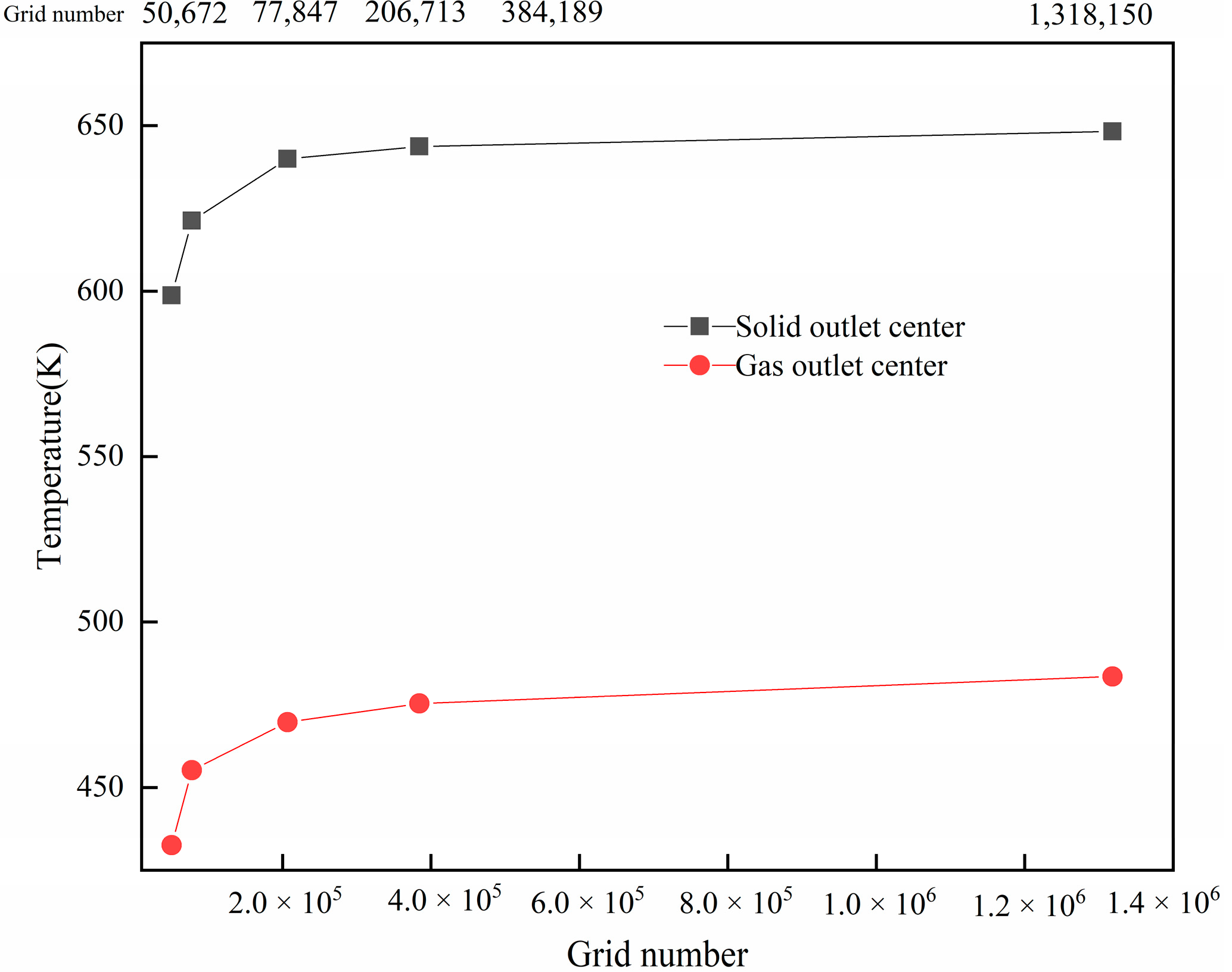
3. Grid Independence Verification

To ensure grid independence, the length, diameter, and location of the thermal desorption chamber were set as 12, 0.7, and 8.5 m, respectively, the feeding speed was set as 0.01 m/s, and the volume fraction of the nitrogen and liquid contents were set as 0.1 and 0.3, respectively. After the model was set as solid and fluid domains, the inlet, gas outlet, solid outlet, heat wall, and symmetry of the fluid domain were defined at identical boundary conditions. Finally, five different grids were used for the numerical calculation.
The grid independence verification results are shown in Figure 3. As the number of grids increased, the temperature variation range at the centre of the solid and gas discharge outlets became increasingly small. The number of grids increased from 206,713 to 384,189 with a growth rate of 85.86%. The temperature change rate of the solid and gas outlets were 0.59% and 1.2%, respectively. To reduce the computer resources used, 206,713 was selected as the grid number.

4. Result Analysis and Discussion

4.1. Influence of Thermal Desorption Chamber Structure on Temperature Field

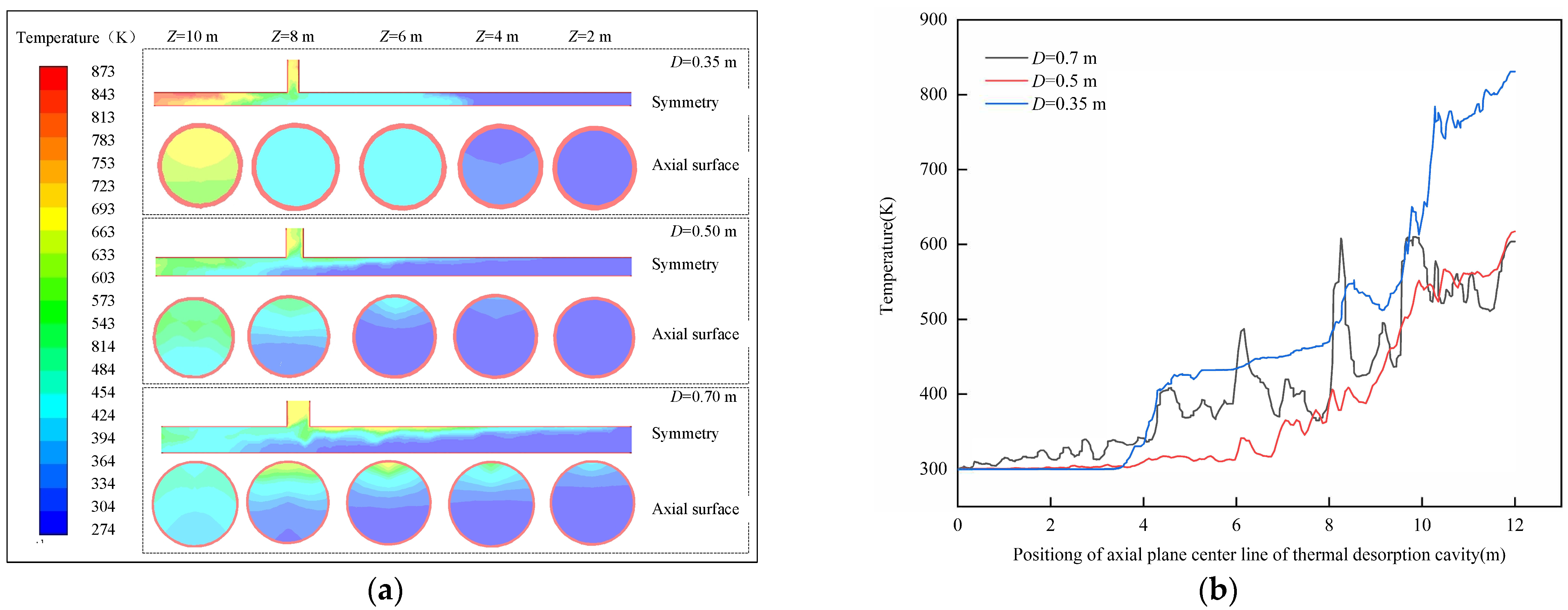
4.1.1. Influence of Chamber Diameter on Temperature Field

Figure 4 shows the temperature field cloud diagram and curve. The temperature of the thermal desorption chamber discharge port decreased with an increase in the chamber diameter. The oil-based drill cuttings in the chamber rapidly absorbed heat when the diameters were 0.35 and 0.5 m. The chamber inlet temperature field colour for dark blue was 4 m, there were many continuous endothermic stages for the oil-based drill cuttings, and the chamber in the body was a constant temperature and not conducive to evaporation. Further, the water and adhesion in the propeller and chamber wall may increase the mechanical torque. The probability of equipment fatigue damage increased, and the length of the chamber was 4–8 m, which was relatively stable and had low temperatures. With this diameter range, the vapour temperature in the upper part of the chamber was low, which was easy to cause the condensation of the thermal desorption vapour again, which was not conducive to the post-treatment residue oil content standards; however, when the length of the chamber was 8–10 m, the temperature in the chamber suddenly rose, resulting in the outlet residue discharge carrying considerable wasted heat. When the diameter was 0.7 m, these deficiencies were better avoided. A comprehensive comparison showed that the diameter of the thermal desorption chamber was appropriately increased and the heat transfer area was larger, which was conducive to the effective utilisation of heat in the thermal desorption chamber.

4.1.2. Influence of Chamber Length on Temperature Field in Chamber

Figure 5 shows the temperature field cloud diagram and curve. As the chamber length increased, the solid discharge port temperature of the chamber increased. When the length of the chamber was 10 m, the central temperature of the outlet axial surface was approximately 400 K. When the temperature near the solid outlet was lower than the desorption temperature of the diesel component, there was a possibility that the oil vapour would re-enter the thermal desorption residue after condensation, leading to the possibility that the oil content of the residue exceeded the standard. When the length of the chamber was 14 m, the temperature near the solid discharge port was higher and the heat loss carried by the residue increased.
The longer the chamber, the larger the thermal desorption heating area, but the screw propeller and motor torque increased, and the probability of failure and damage increased. When mechanical conditions permitted, appropriately extending the length of the thermal desorption chamber was beneficial to improve the heat transfer efficiency of the oil-based drill cuttings’ thermal desorption. In this model, the temperature field distribution in the chamber was more reasonable when the length of the thermal desorption chamber was 12 m.

4.1.3. Influence of Extraction Tube Position on Internal Temperature Field of Thermal Desorption Chamber

All gases in the chamber, including nitrogen, water vapour, oil, and steam, are collected using an extraction pipe after thermal desorption. The extraction of the gas pipe helped estimate these desorption levels and gas temperatures, while preventing post-discharge oil vapour condensation in the thermal desorption chamber in low temperatures and thermal release of excess oil content in the residue.
Figure 6 shows the temperature field cloud diagram and curve when the extraction tube position was 6.5 m; the position of the thermal desorption chamber after 8 m showed high temperatures, with a local maximum of 873 K. The chamber easily reduced its life due to the uneven deformation caused by heating. When the extraction tube was at 10.5 m, there was a temperature increase near 11 m. When the oil-based drill cuttings moved to this position, the water and oil had already desorbed, and the residue was continuously heated. The gas in the thermal desorption chamber also continued to absorb heat during the migration to the extraction tube, which increased the heat loss. Overall, the extraction tube position should be set to approximately 6.5–10.5 m; that is, the extraction tube distance from the inlet of the chamber to the length of the chamber is approximately 0.54–0.88, and the temperature field distribution in the chamber is reasonable.

4.2. Influence of Operating Parameters and Liquid Content on Internal Temperature Field of Thermal Desorption Chamber

4.2.1. Influence of Feeding Speed on Internal Temperature Field of Thermal Desorption Chamber

Figure 7 shows the temperature field cloud diagram and curve, with an increase in the feeding speed; the blue area in the chamber temperature field clouds increased, the colour became darker, and the temperature between the extraction tube and the solid discharge port decreased significantly. When the feed velocity was v = 0.005 m/s, the thermal desorption residue and the extraction pipe oil vapour temperature were high, and the heat loss was relatively large. When the feed speed was v = 0.02 m/s, the chamber temperature was approximately 424 K, and the oil-based cuttings in the petroleum hydrocarbon components of the high carbon elements could not reach the desorption temperature; that is, it is an incomplete reaction with a high-residue oil rate. Therefore, for this model, the temperature field distribution in the thermal desorption chamber was more reasonable when the feed speed was greater than 0.005 m/s and less than 0.02 m/s, which could ensure that the outlet temperature was not lower than the upper threshold of diesel boiling point.

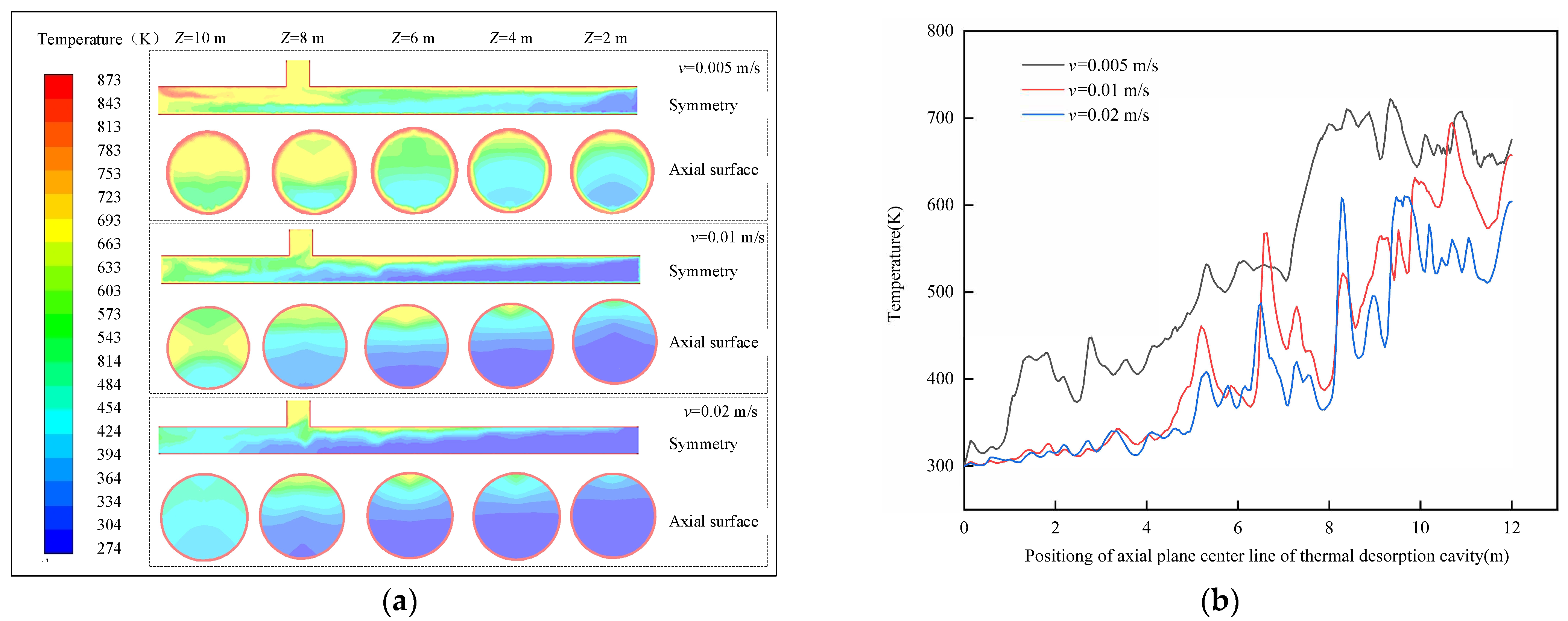
4.2.2. Influence of Inert Gas Entry Velocity on Internal Temperature Field of Thermal Desorption Chamber

Figure 8 shows the temperature field cloud diagram and curve with the increase in the nitrogen inflow speed. The temperature of the chamber declined, and the nitrogen volume fraction was 0.1. The inlet needed to extract the pipe mouth chamber between the temperature curve significantly increased, and the nitrogen gas extracted from tube after collection was no longer able to absorb heat; therefore, the thermal desorption chamber temperature remained unchanged. The more nitrogen that was injected, the greater the energy consumption; however, nitrogen accelerated the flow rate of the gas in the chamber and increased the collision frequency of the particles, which may promote the diffusion, migration, and desorption of the thermal desorption gas in the process of the particle convection heat transfer and accelerate the heat transfer speed. Overall, to guarantee the safety of the chamber, lower nitrogen entry velocities are better. As for the results of the model assignment, when the nitrogen volume fraction was 0.1, the temperature field distribution in the chamber was better than the other two conditions.

4.3. Influence of Oil-Based Drill Cuttings Liquid Content on Temperature Field in Thermal Desorption Chamber

As can be seen from the temperature field cloud diagram and curve in Figure 9, when the volume fraction of the liquid content increased from 0.1 to 0.2, the temperature field colour of blue became dark, indicating that the temperature of the chamber at this stage did not decrease significantly with the increase in the volume fraction of the liquid content, and this stage is the main stage of the massive heat absorption of oil-based drill cuttings. When the volume fraction of the liquid content continued to increase to 0.3, the blue colour increased, while the colour decreased when the length of the thermal desorption chamber was between 0 and 8 m. When the length of the thermal desorption chamber was from 8 to 12 m, the colour became dark, and the temperature evidently decreased. With the increase in the liquid content of the oil-based drill cuttings, the internal temperature of the thermal desorption chamber decreased considerably. The specific heat capacities of the water and oil in the oil-based drill cuttings were higher than that of the thermal desorption residue at constant pressures. Compared with the effects of the feed speed and nitrogen on the internal temperature field of the thermal desorption chamber, the liquid content had a more significant influence on the internal temperature field of the thermal desorption chamber.

4.4. Model Verification

The thermal desorption device selected for the experiment had a cavity length of 12 m, diameter of 0.7 m, and extraction tube position of 8.5 m. The feed rate was set as 0.01 m/s, and the heating temperature was set as 873 K. Five kinds of simulated oil-based drill cuttings with fluid contents of 0.05, 0.1, 0.2, 0.3, and 0.4 were prepared with #0 diesel, water, and dried drill cuttings. When the operating temperature was stable and the residues were discharged evenly, the thermocouple readings T1 at the connection of the extraction tube to the cavity was recorded. At the same time, the temperature in this place was simulated using the method in Section 4.3 and was noted as T0. The comparison results of the experimental and simulated temperatures were shown in Table 3:
From Table 3, T0 was greater than T1 when the fluid content was the same. The main reason for this phenomenon is that the simulated temperature was always 873 K, while the experimental temperature was inhomogeneous due to the energy supplied by multiple burners and because the higher the liquid content, the lower the temperature at the top of the chamber and the greater the error. In engineering applications, errors of up to 13.3% [18] are permitted. In contrast, the error between the simulated and experimental temperatures obtained using this simulation method was between 6.36% and 12.85%. Therefore, the model was basically reliable.

5. Conclusions

(1)
The thermal desorption chamber was simplified as a “T”-shaped tube, and the physical model of the thermal desorption chamber was established. The VOF multiphase flow phase transformation model was selected, with the main phase set as nitrogen. The oil-based drill cuttings were regarded as a mixture of thermal desorption residue, water, and diesel oil. Three-phase mixing was conducted according to different volume fractions. K-epsilon flow patterns were selected in the Fluent software through Reynolds and Stokes number calculations, allowing for the corresponding material properties to be set.
(2)
The structure of the thermal desorption chamber had a great influence on the heat transfer process, and its optimisation can improve the heat transfer efficiency or heat energy utilisation. Appropriately increasing the diameter and length of the thermal desorption chamber was beneficial for the thermal desorption heat transfer process of the oil-based drill cuttings. For this model, the temperature field distribution in the chamber was more reasonable when the chamber was 0.7 m, the length was 12 m, and the ratio between the extraction tube and the inlet of the chamber to the length of the chamber was approximately 0.54–0.88.
(3)
The oil-based drill cuttings thermal desorption chamber temperature decreased considerably with an increase in the feed velocity, nitrogen entry velocity, and liquid content, among which the liquid content had the most significant effect. The higher the liquid content, the lower the temperature of the front end of the extraction tube in the thermal desorption chamber, at which point, the back end of the extraction tube continued to desorb and absorb heat due to the fact of incomplete liquid phase evaporation, but there was a risk that the thermal desorption residue did not meet the standard. Therefore, it is crucial to reduce the standard of the index and the liquid content of oil-based drill cuttings via pretreatment for thermal desorption energy saving and consumption reduction.
(4)
The above research results reveal the effect of three factors, including the liquid content of the oil-based cuttings, the structure of the thermal desorption device, and the operating process parameters, on the temperature field in the cavity during thermal desorption. By using this simulation method, we saved more time and cost, designed and manufactured equipment, optimised the process parameter scheme, guided the pretreatment of the oil-based drill cuttings, and realised the role of improving heat utilisation and energy conservation.

Author Contributions

Methodology, software, and writing—original draft preparation, M.W.; writing—review and editing Y.L. All authors have read and agreed to the published version of the manuscript.

Funding

This research received no external funding.

Institutional Review Board Statement

Not applicable.

Informed Consent Statement

Not applicable.

Data Availability Statement

No new data were created.

Acknowledgments

We acknowledge the editors and the anonymous reviewers for their insightful suggestions on this work.

Conflicts of Interest

The funders had no role in the design of the study; in the collection, analyses, or interpretation of data; in the writing of the manuscript; or in the decision to publish the results.

References

  1. Liu, J.B.; Li, Q.Q. Leaching behavior and mineralogical evolution of vanadium released from sodium roasted-acid leaching tailing of vanadium slag. J. Iron Steel Res. Int. 2022, 29, 772–782. [Google Scholar] [CrossRef]
  2. Hu, G.J.; Liu, H. Low-temperature thermal desorption and secure landfill for oil-based drill cuttings management: Pollution control, human health risk, and probabilistic cost assessment. J. Hazard. Mater. 2021, 410, 124570–124571. [Google Scholar] [CrossRef] [PubMed]
  3. Robinson, P.; Kingman, S.W.; Snape, C.E.; Bradshaw, S.M.; Bradley, M.S.A.; Shang, H.; Barranco, R. Scale-up and design of a continuous microwave treatment system for the processing of oil-contaminated drill cuttings. Chem. Eng. Res. Des. 2010, 88, 146–154. [Google Scholar] [CrossRef]
  4. Irineu, P.; André, L.M. Development and performance of a continuous industrial microwave dryer for remediation of drill cuttings. J. Pet. Sci. Eng. 2019, 176, 362–368. [Google Scholar]
  5. Irineu, P.; Marina, S.P. Microwave remediation of oil well drill cuttings. J. Pet. Sci. Eng. 2015, 134, 23–29. [Google Scholar]
  6. Nwosu, B.E.; Ogbonna, F.J. Treatment Efficiency of Drill Cuttings Using Thermal Desorption Technology. J. Eng. Res. Rep. 2021, 21, 1–12. [Google Scholar]
  7. Peng, S.Z.; Yu, X. Research and Application of Thermal-desorption Treatment of Oil-based Cuttings from Shale Gas Production. Environ. Prot. Oil Gas Fields 2019, 29, 37–40. [Google Scholar]
  8. Chen, H.T. Development and Application of Thermal Desorption Device for Offshore Platform Oil-based Drill Cuttings. Oilfield Equip. 2020, 49, 79–84. [Google Scholar]
  9. Liu, Y.C.; Wang, M.R. Research progress in the oil-based cuttings thermal desorption technology. Nat. Gas Ind. 2020, 40, 140–148. [Google Scholar]
  10. Ji, H.G.; Huan, L. Life cycle assessment of low-temperature thermal desorption-based technologies for drill cuttings treatment. J. Hazard. Mater. 2021, 401, 123861–123865. [Google Scholar]
  11. Zoller, R.J. Schmidt, Managing Drill Cuttings. Pollut. Eng. 2014, 46, 34–37. [Google Scholar]
  12. Jamshidi, N.; Farhadi, M.; Ganji, D.D.; Sedighi, K. Experimental analysis of heat transfer enhancement in shell; helical tube heat exchangers. Appl. Therm. Eng. 2013, 51, 652–664. [Google Scholar] [CrossRef]
  13. Tian, Z.S. Equipment system and engineering practice of soil thermal desorption technology. China Environ. Prot. Ind. 2022, 2, 59–60. [Google Scholar]
  14. Liu, H.; Li, J. Remediation of oil-based drill cuttings using low-temperature thermal desorption: Performance and kinetics modeling. Chemosphere 2019, 235, 1081–1088. [Google Scholar] [CrossRef]
  15. Hui, W.G.; Biao, W.D. Experimental and numerical study on heat transfer and flow characteristics in the shell side of helically coiled trilobal tube heat exchanger. Appl. Therm. Eng. 2019, 14, 772–787. [Google Scholar]
  16. Fan, F.H.; Zheng, M. Numerical study of fluid dynamics and heat transfer property of dual fluidized bed gasifier. Energy 2021, 234, 121241–121246. [Google Scholar] [CrossRef]
  17. Ali, R.; Singh, A. Numerical Study of Fluid Dynamics and Heat Transfer Characteristics for the Flow Past a Heated Square Cylinder. Jordan J. Mech. Ind. Eng. 2021, 15, 357–376. [Google Scholar]
  18. Zhao, F.; Li, Y. Flow and heat transfer characteristics of oil-based drilling cuttings in a screw-driving spiral heat exchanger. Appl. Therm. Eng. 2020, 181, 115881. [Google Scholar]
  19. Gao, N.; Jia, X. Modeling and simulation of coupled pyrolysis and gasification of oily sludge in a rotary kiln. Fuel 2020, 279, 118152. [Google Scholar] [CrossRef]
  20. Peng, X.Q.; Gao, W.Y. Numerical Simulation of Influence of Rotary Speed on Temperature Field of Oil-based Drilling Cuttings Pyrolysis Furnace. Environ. Prot. Oil Gas Fields 2019, 29, 33–36. [Google Scholar]
  21. Nguyen, D.; San, J. Decrement in heat transfer effectiveness due to solid heat conduction for a counter-current spiral heat exchanger. Appl. Therm. Eng. 2016, 103, 821–831. [Google Scholar] [CrossRef]
  22. Yong, Z.X.; Guo, Y.A. Bench test on thermal desorption dispose of oily cuttings. J. Pet. Explor. Prod. Technol. 2018, 9, 663–668. [Google Scholar]
  23. Santos, J.M.; Petri, I.J. Optimization of the batch decontamination process of drill cuttings by microwave heating. J. Pet. Sci. Eng. 2018, 163, 349–358. [Google Scholar] [CrossRef]
  24. Yong, Z.X.; Yao, A.G. Pilot experiment of oily cuttings thermal desorption and heating characteristics study. J. Pet. Explor. Prod. Technol. 2019, 9, 1263–1270. [Google Scholar]
  25. Fei, H.Y.; Dong, Q.S. The study on pyrolysis of oil-based drilling cuttings by microwave and electric heating. J. Environ. Manag. 2018, 228, 312–318. [Google Scholar]
  26. Wang, J.J. Study on Kinetics and the Heat and Mass Transfer Characteristics of Oily Sludge Pyrolysis. Master’s Thesis, College of Pipeling and Civil Engineering China University of Petroleum (East China), Qingdao, China, 2013. [Google Scholar]
Figure 1. Schematic of a thermal desorption chamber: (1) feed port; (2) feed air lock; (3) heating chamber; (4) thermal desorption gas collection chamber; (5) extraction pipe; (6) propeller; (7) discharge air lock; (8) discharge port; (9) inert gas inlet.
Processes 11 01374 g001
Figure 2. Schematic of a simplified thermal desorption chamber profile.
Processes 11 01374 g002
Figure 3. Grid independence verification.
Processes 11 01374 g003
Figure 4. (a) Temperature field cloud of the chamber symmetry plane and axial plane with different diameters of the thermal desorption chamber; (b) temperature curve of the centre of the chamber symmetry plane when the diameter of the thermal desorption chamber was different.
Processes 11 01374 g004
Figure 5. (a) Temperature field cloud of the chamber symmetry plane and axial plane with different lengths of the thermal desorption chamber; (b) temperature curve of the centre of the chamber symmetry plane when the lengths of the thermal desorption chambers differed.
Processes 11 01374 g005
Figure 6. (a) Temperature field clouds of the chamber symmetry plane and axial plane when the extraction tube position of the thermal desorption chamber was different; (b) temperature curve of the centre line of the chamber symmetry plane when the tube positions differed.
Processes 11 01374 g006
Figure 7. (a) Temperature field clouds of the chamber symmetry plane and axial plane with different feeding speeds; (b) temperature curve of the centre of the chamber symmetry plane when the feeding speeds differed.
Processes 11 01374 g007
Figure 8. (a) Temperature field clouds of the chamber symmetry plane and axial plane with different entry velocities of the inert gas; (b) Temperature curve of the centre of the chamber symmetry plane when the inert gas entering velocities were different.
Processes 11 01374 g008
Figure 9. (a) Temperature field clouds of the chamber symmetry plane and axial plane with different fluid contents of oil-based drill cuttings; (b) temperature curve of the centre line of the chamber symmetry plane with the different fluid contents of the oil-based drill cuttings.
Processes 11 01374 g009
Table 1. Main geometric parameters and variation range of a thermal desorption chamber.
Structural ParameterNumerical Range
Diameter of the thermal desorption chamber350–700 mm
Length of the thermal desorption chamber10–14 m
Extraction tube is located away from the feed port6.5–10.5 m
Table 2. Main parameters required for the oil-based drill cuttings simulation [26].
Coefficient of Thermal Conductivity0.89 W/(m2·°C)Specific Heat Capacity900 J/(kg·°C)
Kinematic viscosity2.28 × 10−3 Pa·sDiameter of oil-based cuttings0.1~1.5 cm
Table 3. Comparison of simulated and experimental temperatures.
Fluid ContentT0T1ErrorFluid ContentT0T1Error
0.055024726.360.337333511.34
0.14253889.540.432528812.85
0.240836910.57
Disclaimer/Publisher’s Note: The statements, opinions and data contained in all publications are solely those of the individual author(s) and contributor(s) and not of MDPI and/or the editor(s). MDPI and/or the editor(s) disclaim responsibility for any injury to people or property resulting from any ideas, methods, instructions or products referred to in the content.

